EP3125426A1 - Method for designing multiple tuned filter in high voltage direct current system - Google Patents
Method for designing multiple tuned filter in high voltage direct current system Download PDFInfo
- Publication number
- EP3125426A1 EP3125426A1 EP16173104.7A EP16173104A EP3125426A1 EP 3125426 A1 EP3125426 A1 EP 3125426A1 EP 16173104 A EP16173104 A EP 16173104A EP 3125426 A1 EP3125426 A1 EP 3125426A1
- Authority
- EP
- European Patent Office
- Prior art keywords
- harmonic
- filter
- mtf
- objective function
- value
- Prior art date
- Legal status (The legal status is an assumption and is not a legal conclusion. Google has not performed a legal analysis and makes no representation as to the accuracy of the status listed.)
- Granted
Links
Images



Classifications
-
- H—ELECTRICITY
- H02—GENERATION; CONVERSION OR DISTRIBUTION OF ELECTRIC POWER
- H02J—ELECTRIC POWER NETWORKS; CIRCUIT ARRANGEMENTS OR SYSTEMS FOR SUPPLYING OR DISTRIBUTING ELECTRIC POWER; SYSTEMS FOR STORING ELECTRIC ENERGY
- H02J3/00—Circuit arrangements for AC mains or AC distribution networks
- H02J3/01—Arrangements for reducing harmonics or ripples
-
- G—PHYSICS
- G06—COMPUTING OR CALCULATING; COUNTING
- G06F—ELECTRIC DIGITAL DATA PROCESSING
- G06F30/00—Computer-aided design [CAD]
- G06F30/30—Circuit design
-
- H—ELECTRICITY
- H02—GENERATION; CONVERSION OR DISTRIBUTION OF ELECTRIC POWER
- H02J—ELECTRIC POWER NETWORKS; CIRCUIT ARRANGEMENTS OR SYSTEMS FOR SUPPLYING OR DISTRIBUTING ELECTRIC POWER; SYSTEMS FOR STORING ELECTRIC ENERGY
- H02J3/00—Circuit arrangements for AC mains or AC distribution networks
- H02J3/36—Arrangements for transfer of electric power between AC networks via high-voltage DC [HVDC] links; Arrangements for transfer of electric power between generators and networks via HVDC links
-
- H—ELECTRICITY
- H03—ELECTRONIC CIRCUITRY
- H03H—IMPEDANCE NETWORKS, e.g. RESONANT CIRCUITS; RESONATORS
- H03H7/00—Multiple-port networks comprising only passive electrical elements as network components
- H03H7/01—Frequency selective two-port networks
-
- H—ELECTRICITY
- H03—ELECTRONIC CIRCUITRY
- H03H—IMPEDANCE NETWORKS, e.g. RESONANT CIRCUITS; RESONATORS
- H03H7/00—Multiple-port networks comprising only passive electrical elements as network components
- H03H7/01—Frequency selective two-port networks
- H03H7/0115—Frequency selective two-port networks comprising only inductors and capacitors
-
- H—ELECTRICITY
- H02—GENERATION; CONVERSION OR DISTRIBUTION OF ELECTRIC POWER
- H02J—ELECTRIC POWER NETWORKS; CIRCUIT ARRANGEMENTS OR SYSTEMS FOR SUPPLYING OR DISTRIBUTING ELECTRIC POWER; SYSTEMS FOR STORING ELECTRIC ENERGY
- H02J3/00—Circuit arrangements for AC mains or AC distribution networks
- H02J3/36—Arrangements for transfer of electric power between AC networks via high-voltage DC [HVDC] links; Arrangements for transfer of electric power between generators and networks via HVDC links
- H02J2003/365—Reducing harmonics or oscillations in HVDC
-
- H—ELECTRICITY
- H03—ELECTRONIC CIRCUITRY
- H03H—IMPEDANCE NETWORKS, e.g. RESONANT CIRCUITS; RESONATORS
- H03H7/00—Multiple-port networks comprising only passive electrical elements as network components
- H03H7/01—Frequency selective two-port networks
- H03H2007/013—Notch or bandstop filters
Definitions
- the present disclosure relates to a method for designing a multiple tuned filter (hereinafter, referred to as 'MTF') according to characteristics of a high voltage direct current (hereinafter, referred to as 'HVDC') system.
- 'MTF' multiple tuned filter
- 'HVDC' high voltage direct current
- a harmonic filter prevents harmonics generated in power conversion through the operation of a converter from being introduced into an AC system, and also serves as a reactive power supply source in consumption of reactive power.
- a majority of current type HVDC systems operates with 12 pulses, and hence generates characteristic harmonics of 12n ⁇ 1 orders such as 11th, 13th, 23rd, and 25th orders.
- 11th- and 13th-order filters are used to decrease the magnitudes of the 11th- and 13th-order harmonics.
- a converter In the current type HVDC systems, a majority of converters operate with 12 pulses. In an 80 kV 60 MW HVDC system currently installed in Jeju, Korea, a converter is also configured as a 12-pulse converter using a serial connection of two 6-pulse groups.
- a single tuned filter (STF) or double tuned filter (DTF) is widely used as the harmonic filter.
- Formulae for serial and parallel impedances of the filter may be used to design the filter.
- the design of a filter is made by passive calculation based on design ratings or performances of passive elements included in the filter. Therefore, any accurate, efficient, and standardized manner or method does not exist.
- Embodiments provide an MTF according to characteristics of an HVDC system, a method for designing a damped type MTF, and a designing device.
- a method for designing an MTF in an HVDC system includes: setting an input parameter constituting the MTF; setting a resonance frequency of the MTF; extracting at least one LC combination case constituting the MTF on the basis of the input parameter and the resonance frequency; performing optimization for harmonic reduction on the LC combination case; and extracting an LC combination case determined based on a result obtained by performing the optimization.
- an MTF in an HVDC system, which has an optimal combination of R, L, and C, which satisfies a harmonic voltage regulation value and a harmonic current allowable level by considering efficiency and harmonic reduction through the above-described method.
- Fig. 1 is a configuration diagram illustrating a general HVDC system.
- FIG. 1 an MTF installable in an 80 kV HVDC system is illustrated in the HVDC system.
- the 80 kV HVDC system has a typical bi-electrode system, and is configured with a 12-pulse converter having the same two electrodes.
- the converter of the HVDC system may generate a harmonic current of a specified value or more. Therefore, unless filtering is performed, the harmonic current may create distortion in an AC voltage and disturb a normal operation of the system.
- a harmonic filter allows a harmonic current to flow out therethrough by forming a parallel line having small impedance, so that the harmonic current is within a range in which the distortion of an AC voltage can be permitted.
- the 12-pulse converter has characteristic harmonics of 12n ⁇ 1 orders. Therefore, harmonic components required in the filter may be 11th-, 13th-, 23rd-, and 25th-order components. Harmonic components of orders higher than the11th, 13th, 23rd, and 25th orders may be attenuated by a high-pass filter.
- the 80 kV HVDC system may include an MTF and a high-pass filter, which compensate for a reactive power of 17 Mvar.
- MTF a high-voltage capacitor bank C1 and a low-voltage air core reactor L1 may be coupled in series to each other, and a low-voltage capacitor bank C2 and an air core reactor L2 may be coupled in parallel to each other.
- the harmonic filter may function to supply reactive power to the system at 60 Hz.
- Fig. 2 is a configuration diagram illustrating a harmonic equivalent model corresponding to an HVDC system in which a harmonic filter is embedded.
- a current type HVDC converter may absorb reactive power from an AC system and supply reactive power required in the converter through a harmonic filter.
- the HVDC converter may be modeled as a constant current harmonic power source in an AC stage thereof, and may be modeled as a constant voltage harmonic power source at a DC stage thereof.
- the harmonic filter functions to prevent harmonics generated in the HVDC converter from being introduced into the AC system, and hence a harmonic equivalent model using a constant current harmonic power source in an AC stage thereof as shown in Fig. 2 may be used as the harmonic filter.
- I n denotes a harmonic current generated from the HVDC converter
- I fn and I sn denote harmonic currents introduced into the filter and the AC system, respectively.
- Z fn and Z sn denote harmonic impedances of the AC system, respectively, and V sn denotes a harmonic voltage of the AC system.
- the performance of the harmonic filter depends on an admittance value of the AC system. Since the admittance value of the AC system is temporally varied depending on a state of an actual power system, it is difficult to obtain an exact admittance value at a given frequency. Therefore, in the design of a harmonic filter, admittance at a given frequency may be determined on a complex plane having an admittance angle as a boundary.
- Fig. 3 is an exemplary diagram illustrating a method for designing an MTF using an equivalent circuit manner according to an embodiment.
- a harmonic filter In a harmonic filter, cost corresponding to one bank is generated.
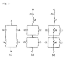
- a harmonic filter implemented by coupling the same filter banks in parallel to each other as shown in Fig. 3(b) or 3(c) uses a smaller space in removal of the same number of harmonics than a harmonic filter using two single tuned filters (hereinafter, referred to as 'STFs') to remove two harmonics as shown in Fig. 3(a) , which is economically advantageous.
- a damped-type MTF including a damping resistor R coupled in parallel to a parallel LC resonance tank as shown in Fig. 3(c) may be used.
- the equivalent circuit manner may be a manner that can be relatively easily approached in the design of an MTF.
- the total amount of reactive power to be compensated is equally distributed to STFs, and a parameter value of each STF is selected.
- the parameter value of the STF When the parameter value of the STF is selected, it is required to determine the magnitude of a voltage applied to the filter and the amount of reactive power to be compensated by the filter.
- the reactance of the filter may be a difference in reactance between the capacitor and inductor.
- the impedance of the entire filter in an hth-order harmonic is to be a value of 0, and therefore, the reactance of the capacitor is equal to a value obtained by multiplying the reactance of the inductor by the square of h.
- a converter of the HVDC system generates a harmonic current of a specified value or more, and therefore, a harmonic filter is installed to allow the harmonic current to flow out therethrough, so that the harmonic current is within a range in which the distortion of an AC voltage can be permitted.
- the 12-pulse converter has characteristic harmonics of 12n+1 orders. Therefore, harmonic components required in the filter are 11th-, 13th-, 23rd-, and 25th-order components. Harmonic components of orders higher than the11th, 13th, 23rd, and 25th orders may be attenuated by a high-pass filter.
- a high-voltage capacitor bank C1 and a low-voltage air core reactor L1 may be coupled in series to each other, and a low-voltage capacitor bank C2 and an air core reactor L2 may be coupled in parallel to each other.
- the MTF may be configured by coupling in series a plurality of LC resonance tanks each configured by coupling a low-voltage capacitor bank C3 and an air core reactor L3 in parallel to each other according to harmonics to be removed.
- the harmonic filter functions to supply reactive power to the system at 60 Hz. Therefore, terminals of a rectifier and an inverter absorb reactive power in proportion to active power exchanged between a converter and an AC system. Since the harmonic filter uses capacitors, it is possible to supply required reactive power to the converter. If reactive power is not sufficiently compensated from the filter, an AC voltage at the terminal may not have a sufficient magnitude for normally operating the converter.
- an HVDC converter is a constant voltage harmonic power source in a DC stage, and may be modeled as a constant current harmonic power source in an AC stage. Since it is one of the functions of the filter to prevent harmonics generated in the HVDC converter from being introduced into the AC system, it is required to perform modeling for harmonic analysis in the AC stage.
- a filter and a power system e.g., an AC system coupled thereto may be expressed or modeled using impedance.
- a filter may be designed after a degree where a harmonic current generated in the converter is introduced into the system and harmonic characteristics of a voltage corresponding to the degree are figured out using the model of Fig. 2 .
- a model can be easily implemented by changing a resistance value in the filter so as to improve the stabilization of a relationship between the filter and the power system coupled thereto.
- Fig. 4 is a block configuration diagram illustrating a filter parameter setting device of the MTF to which the embodiment is applied.
- filter parameter setting device 100 may include an input unit 110, a storage unit 120, and a controller 130.
- the input unit 110 may function to receive an input parameter and a resistance value corresponding to the MTF.
- the input unit 110 allows a user to generate input data for controlling an operation of the filter parameter setting device 100.
- the input unit 110 may be configured as a keypad, a dome switch, a touch pad, a jog wheel, a jog switch, or the like.
- the input unit 110 may function to interface with all external devices coupled to the filter parameter setting device 100.
- the storage unit 120 may store processing of the controller 130 and a program for control.
- the storage unit 120 may function to arbitrarily store input/output data (input parameters and resistance values) and result data calculated and computed by the controller 130 or store them as final result data.
- the storage unit 120 may store information on a weighted value of an individual objective function and data on combinations of L and C as filter components.
- the storage unit 120 may store information on evaluation for forming a filter having an optimal combination of L and C to which the weighted value of the individual objective function is applied and information on a number of times of the evaluation.
- the controller 130 may function to control the general operations of the filter parameter setting device 100, which are performed in the filter parameter setting device 100.
- the controller 130 may be implemented in the form of a microcontroller or microprocessor.
- the controller 130 may set a resonance frequency corresponding to the MTF and a resistance value within a preset reference range. Also the controller 130 may set a parameter value corresponding to the MTF, based on the input parameter, the resonance frequency, and the resistance value.
- the controller 130 may determine whether an individual harmonic component or a total harmonic distortion ratio satisfies a reference value level, and reset the resonance frequency based on a determination result.
- the controller 130 may set or reset the resistance value within the preset range as a load or system is coupled to the MTF, thereby ensuring safety.
- the controller 130 creates a harmonic reduction objective function, and enables a harmonic voltage or harmonic current to be maximally reduced according to the created objective function. Accordingly, it is possible to design an MTF according to weighted value application and compatibility evaluation.
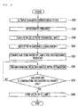
- Figs. 5 and 6 are flowcharts illustrating the method according to the embodiment.
- an input parameter corresponding to the MTF may be set (S510). Specifically, an input parameter corresponding to the MTF may be set when an optimal parameter corresponding to the MTF is set.
- the input parameter may be a parameter related to the rating or target performance of the MTF.
- the input parameter may include at least one of a rated voltage of a load or system coupled to the MTF, reactive power to be compensated by the MTF, and a filtering frequency.
- the load or system coupled to the MTF may be a power system of an HVDC system.
- the power system of the HVDC system may be, for example, an AC system.
- the filtering frequency is a frequency to be filtered by the MTF, and may include a first filtering frequency and a second filtering frequency greater than the first filtering frequency.
- the first filtering frequency may be a frequency corresponding to the 11th-order harmonic component
- the second filtering frequency may be a frequency corresponding to the 13th-order harmonic component
- a resonance frequency of the MTF may be set (S520). Specifically, the set resonance frequency may set an initial value of the resonance frequency, and the setting of the resonance frequency may be performed based on the filtering frequency to be filtered by the MTF.
- the resonance frequency may be set as a frequency that exists within a range between the first and second filtering frequencies.
- the initial value of the resonance frequency may be set as the first filtering frequency.
- values of L and C that become filter parameters forming impedance of a filter to be matched to the resonance frequency may be computed (S530).
- the MTF may include a first LC circuit unit, a second LC circuit unit, and a third LC circuit unit, which are coupled in series to each other.
- the first LC circuit unit may have a structure in which a first capacitor and a first inductor are coupled in series to each other
- the second LC circuit unit may have a structure in which a second capacitor and a second inductor are coupled in parallel to each other.
- the third LC circuit unit may have a structure in which a third capacitor and a third inductor are coupled in parallel to each other.
- the filter parameter may include at least one of a capacitance value of the first capacitor, an inductance value of the first inductor, a capacitance value of the second capacitor, an inductance value of the second inductor, a capacitance value of the third capacitor, and an inductance value of the second inductor.
- the resonance frequency of the filter may be a parallel resonance frequency corresponding to the second and third LC circuit units.
- Filter impedance characteristics of the computed values of L and C are identified (S540), and values of L and C according to the identified filter impedance characteristics may be combined and stored for each resonance frequency (S550). Specifically, cases where the identified filter impedance is included in a preset reference value range may be matched to the values of L and C for each resonance frequency, and the matched cases may be stored.
- the LC combination may be created as one or more various cases.
- Harmonic reduction multi-purpose optimization may be performed on the LC combination for each resonance frequency (S560). Specifically, in the harmonic reduction multi-purpose optimization, an operation for selecting an optimal filter component combination obtained by considering a total harmonic distortion (THD) and a total demand distortion of current (TDD) may be performed on a plurality of combined cases created by the LC combination. The operation for the harmonic reduction multi-purpose optimization will be described in detail with reference to Fig. 6 .
- a harmonic reduction objective function may be formed to perform the harmonic reduction multi-purpose optimization (S610).
- the harmonic reduction objective function may be configured with a first objective function and a second objective function.
- the first objective function is a function having the THD as a minimum, and may maximally reduce a harmonic voltage.
- the first objective function may be represented as shown in the following Equations 1 and 2.
- i is a harmonic number
- V 1 is a fundamental harmonic voltage
- Vi is an i-th harmonic voltage
- Y si is an i-th harmonic admittance of the system
- Y MTFi is MTF's i-th harmonic admittance.
- the first objective function F 1 may calculate a minimum THD on the basis of harmonic voltages of secondary to 50th-order harmonics.
- the second objective function is a function having the TDD as a minimum, and may maximally reduce a harmonic current.
- the second objective function may be represented as shown in Equation 3.
- i is a harmonic number
- I 1 is a fundamental harmonic voltage
- Ii an i-th harmonic current
- the second objective function F 2 may calculate a minimum TDD on the basis of harmonic currents of the secondary to 50th-order harmonics.
- a limiting condition to be applied to the objective function may be set (S620). Specifically, a reactive power demand of the filter may be selected as the limiting condition.
- the limiting condition may additionally include price information or loss information based on the price and number of each of Rs, Ls, and Cs, which constitute the filter. Therefore, secondary filtering may be performed on optimal LC combination cases on the basis of the price information or loss information.
- a weighted value for each of the objective functions may be selected (S630).
- the weighted value W may be configured with a first weighted value W1 to be applied to the first objective function F 1 and a second weighted value W2 to be applied to the second objective function F 2 .
- the weighted value W may be a sum of the first weighted value W1 and the second weighted value W2 as shown in the following Equation 4.
- Total weighted value W first weighted value W 1 + second weighted value W 2
- the total weighted value W i.e., the sum of the first weighted value W1 and the second weighted value W2 may be 1, and the ratio of the first and second weighted values W1 and W2 respectively applied to the first and second objective functions F 1 and F 2 may be varied depending on a harmonic voltage regulation value and a harmonic current allowable level.
- the ratio of the first weighted value W1 applied to the first objective function may be set to "1," and the ratio of the second weighted value W2 applied to the second objective function may be set to "0.”
- the ratio of the first weighted value W1 applied to the first objective function may be set to "0”
- the ratio of the second weighted value W2 applied to the second objective function may be set to "1.” That is, the second weighted value W2 to be applied to the second objective function may be set to be higher than the first weighted value W1.
- the ratios of the first and second weighted values to be respectively applied to the first and second objective functions may be equally applied.
- the above-described ratio of the weighted value applied to the objective function is described as an example, and the ratio of the weighted value applied to the objective function may be set to be varied depending on a weighted value selection reference and a weighted degree of each objective function.
- the compatibility of the first and second objective functions F 1 and F 2 to which the respective weighted values are applied may be evaluated (S640). Specifically, the first and second weighted values W1 and W2 may be respectively applied to the first and second objective functions F 1 and F 2 according to the harmonic voltage regulation value and the harmonic current allowance level, and units are integrated with respect to the first and second objective functions F 1 and F 2 to which the respective weighted values are applied, thereby performing compatibility evaluation.
- the compatibility evaluation may extract a combination case of which result value has a minimum in a state in which objective functions and weighted values are respectively applied to LC combination cases.
- a plurality of LC combination cases may be extracted from the LC combination cases in an order in which they have minimum values according to a compatibility evaluation reference (primary filtering), and secondary filtering for extracting an optimal LC combination case according to price information or loss information among preset limiting conditions may be performed.
- LC combination cases may be extracted in an order in which they have minimum values by computing a single objective function using a sum of the first and second objective functions to which the respective weighted values are applied.
- the multi-purpose optimization may be ended (S650).
- the number of times of extraction may be the number of combination cases of R, L, and C.
- the extracted R, L, and C and a resonance frequency matched thereto may be stored (S580).
- the MTF is coupled to a load or system, based on a resistance value combined through the above-described processes.
Landscapes
- Engineering & Computer Science (AREA)
- Power Engineering (AREA)
- Computer Hardware Design (AREA)
- Physics & Mathematics (AREA)
- Theoretical Computer Science (AREA)
- Evolutionary Computation (AREA)
- Geometry (AREA)
- General Engineering & Computer Science (AREA)
- General Physics & Mathematics (AREA)
- Supply And Distribution Of Alternating Current (AREA)
- Direct Current Feeding And Distribution (AREA)
- Power Conversion In General (AREA)
Abstract
Description
- The present application claims the benefits of priority to
Korean Patent Application No.10-2015-0108403 filed on July 30, 2015 - The present disclosure relates to a method for designing a multiple tuned filter (hereinafter, referred to as 'MTF') according to characteristics of a high voltage direct current (hereinafter, referred to as 'HVDC') system.
- In a HVDC system, a harmonic filter prevents harmonics generated in power conversion through the operation of a converter from being introduced into an AC system, and also serves as a reactive power supply source in consumption of reactive power. A majority of current type HVDC systems operates with 12 pulses, and hence generates characteristic harmonics of 12n±1 orders such as 11th, 13th, 23rd, and 25th orders. Particularly, since magnitudes of 11th- and 13th-order harmonics are large, 11th- and 13th-order filters are used to decrease the magnitudes of the 11th- and 13th-order harmonics.
- In the current type HVDC systems, a majority of converters operate with 12 pulses. In an 80 kV 60 MW HVDC system currently installed in Jeju, Korea, a converter is also configured as a 12-pulse converter using a serial connection of two 6-pulse groups.
- In the HVDC system, a single tuned filter (STF) or double tuned filter (DTF) is widely used as the harmonic filter. Formulae for serial and parallel impedances of the filter may be used to design the filter.
- The design of a filter is made by passive calculation based on design ratings or performances of passive elements included in the filter. Therefore, any accurate, efficient, and standardized manner or method does not exist.
- Embodiments provide an MTF according to characteristics of an HVDC system, a method for designing a damped type MTF, and a designing device.
- In one embodiment, a method for designing an MTF in an HVDC system includes: setting an input parameter constituting the MTF; setting a resonance frequency of the MTF; extracting at least one LC combination case constituting the MTF on the basis of the input parameter and the resonance frequency; performing optimization for harmonic reduction on the LC combination case; and extracting an LC combination case determined based on a result obtained by performing the optimization.
- According to the present disclosure, it is possible to implement an MTF in an HVDC system, which has an optimal combination of R, L, and C, which satisfies a harmonic voltage regulation value and a harmonic current allowable level by considering efficiency and harmonic reduction through the above-described method.
- The details of one or more embodiments are set forth in the accompanying drawings and the description below. Other features will be apparent from the description and drawings, and from the claims.
-
-
Fig. 1 is a configuration diagram illustrating a general HVDC system. -
Fig. 2 is a configuration diagram illustrating a harmonic equivalent model corresponding to an HVDC system in which a harmonic filter is embedded. -
Fig. 3 is an exemplary diagram illustrating a method for designing an MTF using an equivalent circuit manner according to an embodiment. -
Fig. 4 is a block configuration diagram illustrating a filter parameter setting device of the MTF to which the embodiment is applied. -
Figs. 5 and6 are flowcharts illustrating the method according to the embodiment. - Hereinafter, exemplary embodiments will be described in detail with reference to the accompanying drawings. The technical objective of embodiments is not limited to the aforementioned technical problem, and technical problems not mentioned above can be clearly understood by a person skilled in the art by the disclosure below. In the drawings, the sizes, thicknesses and the like of devices are exaggerated for convenience of illustration. Like reference numerals indicate like elements throughout the specification and drawings.
-
Fig. 1 is a configuration diagram illustrating a general HVDC system. - Referring to
Fig. 1 , an MTF installable in an 80 kV HVDC system is illustrated in the HVDC system. The 80 kV HVDC system has a typical bi-electrode system, and is configured with a 12-pulse converter having the same two electrodes. - The converter of the HVDC system may generate a harmonic current of a specified value or more. Therefore, unless filtering is performed, the harmonic current may create distortion in an AC voltage and disturb a normal operation of the system.
- A harmonic filter allows a harmonic current to flow out therethrough by forming a parallel line having small impedance, so that the harmonic current is within a range in which the distortion of an AC voltage can be permitted.
- The 12-pulse converter has characteristic harmonics of 12n±1 orders. Therefore, harmonic components required in the filter may be 11th-, 13th-, 23rd-, and 25th-order components. Harmonic components of orders higher than the11th, 13th, 23rd, and 25th orders may be attenuated by a high-pass filter.
- The 80 kV HVDC system may include an MTF and a high-pass filter, which compensate for a reactive power of 17 Mvar. In the MTF, a high-voltage capacitor bank C1 and a low-voltage air core reactor L1 may be coupled in series to each other, and a low-voltage capacitor bank C2 and an air core reactor L2 may be coupled in parallel to each other. Here, the harmonic filter may function to supply reactive power to the system at 60 Hz.
-
Fig. 2 is a configuration diagram illustrating a harmonic equivalent model corresponding to an HVDC system in which a harmonic filter is embedded. - Referring to
Fig. 2 , a current type HVDC converter may absorb reactive power from an AC system and supply reactive power required in the converter through a harmonic filter. - The HVDC converter may be modeled as a constant current harmonic power source in an AC stage thereof, and may be modeled as a constant voltage harmonic power source at a DC stage thereof. The harmonic filter functions to prevent harmonics generated in the HVDC converter from being introduced into the AC system, and hence a harmonic equivalent model using a constant current harmonic power source in an AC stage thereof as shown in
Fig. 2 may be used as the harmonic filter. - Here, In denotes a harmonic current generated from the HVDC converter, and Ifn and Isn denote harmonic currents introduced into the filter and the AC system, respectively. Zfn and Zsn denote harmonic impedances of the AC system, respectively, and Vsn denotes a harmonic voltage of the AC system.
- The performance of the harmonic filter depends on an admittance value of the AC system. Since the admittance value of the AC system is temporally varied depending on a state of an actual power system, it is difficult to obtain an exact admittance value at a given frequency. Therefore, in the design of a harmonic filter, admittance at a given frequency may be determined on a complex plane having an admittance angle as a boundary.
-
Fig. 3 is an exemplary diagram illustrating a method for designing an MTF using an equivalent circuit manner according to an embodiment. - Referring to
Fig. 3 , when an AC filter (or harmonic filter) is designed in an HVDC system, it is necessary to consider harmonic distortion, system reliability, cost, etc. - In a harmonic filter, cost corresponding to one bank is generated. Hence, a harmonic filter implemented by coupling the same filter banks in parallel to each other as shown in
Fig. 3(b) or 3(c) uses a smaller space in removal of the same number of harmonics than a harmonic filter using two single tuned filters (hereinafter, referred to as 'STFs') to remove two harmonics as shown inFig. 3(a) , which is economically advantageous. - In addition, the form of a damped-type MTF including a damping resistor R coupled in parallel to a parallel LC resonance tank as shown in
Fig. 3(c) may be used. - The equivalent circuit manner may be a manner that can be relatively easily approached in the design of an MTF.
- For the design of the MTF, the total amount of reactive power to be compensated is equally distributed to STFs, and a parameter value of each STF is selected.
- When the parameter value of the STF is selected, it is required to determine the magnitude of a voltage applied to the filter and the amount of reactive power to be compensated by the filter.
- Because of the structure of a serial LC filter, a capacitor and an inductor in the serial LC filter are coupled in series to each other, and therefore, the reactance of the filter may be a difference in reactance between the capacitor and inductor.
- Meanwhile, the impedance of the entire filter in an hth-order harmonic is to be a value of 0, and therefore, the reactance of the capacitor is equal to a value obtained by multiplying the reactance of the inductor by the square of h.
- According to the above-described method, a converter of the HVDC system generates a harmonic current of a specified value or more, and therefore, a harmonic filter is installed to allow the harmonic current to flow out therethrough, so that the harmonic current is within a range in which the distortion of an AC voltage can be permitted.
- The 12-pulse converter has characteristic harmonics of 12n+1 orders. Therefore, harmonic components required in the filter are 11th-, 13th-, 23rd-, and 25th-order components. Harmonic components of orders higher than the11th, 13th, 23rd, and 25th orders may be attenuated by a high-pass filter.
- As shown in an exemplary diagram of
Fig. 3(b) , in the MTF, a high-voltage capacitor bank C1 and a low-voltage air core reactor L1 may be coupled in series to each other, and a low-voltage capacitor bank C2 and an air core reactor L2 may be coupled in parallel to each other. In addition, the MTF may be configured by coupling in series a plurality of LC resonance tanks each configured by coupling a low-voltage capacitor bank C3 and an air core reactor L3 in parallel to each other according to harmonics to be removed. - The harmonic filter functions to supply reactive power to the system at 60 Hz. Therefore, terminals of a rectifier and an inverter absorb reactive power in proportion to active power exchanged between a converter and an AC system. Since the harmonic filter uses capacitors, it is possible to supply required reactive power to the converter. If reactive power is not sufficiently compensated from the filter, an AC voltage at the terminal may not have a sufficient magnitude for normally operating the converter.
- Meanwhile, an HVDC converter is a constant voltage harmonic power source in a DC stage, and may be modeled as a constant current harmonic power source in an AC stage. Since it is one of the functions of the filter to prevent harmonics generated in the HVDC converter from being introduced into the AC system, it is required to perform modeling for harmonic analysis in the AC stage.
- Here, a filter and a power system (e.g., an AC system) coupled thereto may be expressed or modeled using impedance.
- A filter may be designed after a degree where a harmonic current generated in the converter is introduced into the system and harmonic characteristics of a voltage corresponding to the degree are figured out using the model of
Fig. 2 . - In addition, a model can be easily implemented by changing a resistance value in the filter so as to improve the stabilization of a relationship between the filter and the power system coupled thereto.
-
Fig. 4 is a block configuration diagram illustrating a filter parameter setting device of the MTF to which the embodiment is applied. - Referring to
Fig. 4 , filterparameter setting device 100 may include aninput unit 110, astorage unit 120, and acontroller 130. - The
input unit 110 may function to receive an input parameter and a resistance value corresponding to the MTF. - The
input unit 110 allows a user to generate input data for controlling an operation of the filterparameter setting device 100. Theinput unit 110 may be configured as a keypad, a dome switch, a touch pad, a jog wheel, a jog switch, or the like. - Also, the
input unit 110 may function to interface with all external devices coupled to the filterparameter setting device 100. - The
storage unit 120 may store processing of thecontroller 130 and a program for control. Thestorage unit 120 may function to arbitrarily store input/output data (input parameters and resistance values) and result data calculated and computed by thecontroller 130 or store them as final result data. According to an embodiment, thestorage unit 120 may store information on a weighted value of an individual objective function and data on combinations of L and C as filter components. Also, thestorage unit 120 may store information on evaluation for forming a filter having an optimal combination of L and C to which the weighted value of the individual objective function is applied and information on a number of times of the evaluation. - The
controller 130 may function to control the general operations of the filterparameter setting device 100, which are performed in the filterparameter setting device 100. - The
controller 130 may be implemented in the form of a microcontroller or microprocessor. Thecontroller 130 may set a resonance frequency corresponding to the MTF and a resistance value within a preset reference range. Also thecontroller 130 may set a parameter value corresponding to the MTF, based on the input parameter, the resonance frequency, and the resistance value. - The
controller 130 may determine whether an individual harmonic component or a total harmonic distortion ratio satisfies a reference value level, and reset the resonance frequency based on a determination result. - The
controller 130 may set or reset the resistance value within the preset range as a load or system is coupled to the MTF, thereby ensuring safety. - The
controller 130 creates a harmonic reduction objective function, and enables a harmonic voltage or harmonic current to be maximally reduced according to the created objective function. Accordingly, it is possible to design an MTF according to weighted value application and compatibility evaluation. - Hereinafter, based on the above-described configuration, the method according to the embodiment will be described in detail with reference to
Figs. 5 and6 . -
Figs. 5 and6 are flowcharts illustrating the method according to the embodiment. - Referring to
Figs. 5 and6 , in the design of an MTF, an input parameter corresponding to the MTF may be set (S510). Specifically, an input parameter corresponding to the MTF may be set when an optimal parameter corresponding to the MTF is set. The input parameter may be a parameter related to the rating or target performance of the MTF. Also, the input parameter may include at least one of a rated voltage of a load or system coupled to the MTF, reactive power to be compensated by the MTF, and a filtering frequency. - The load or system coupled to the MTF may be a power system of an HVDC system. The power system of the HVDC system may be, for example, an AC system.
- The filtering frequency is a frequency to be filtered by the MTF, and may include a first filtering frequency and a second filtering frequency greater than the first filtering frequency.
- For example, when harmonic components to be filtered are the above-described 11th- and 13th-order harmonic components, the first filtering frequency may be a frequency corresponding to the 11th-order harmonic component, and the second filtering frequency may be a frequency corresponding to the 13th-order harmonic component.
- If the input parameter corresponding to the MTF is set, a resonance frequency of the MTF may be set (S520). Specifically, the set resonance frequency may set an initial value of the resonance frequency, and the setting of the resonance frequency may be performed based on the filtering frequency to be filtered by the MTF.
- For example, the resonance frequency may be set as a frequency that exists within a range between the first and second filtering frequencies. Specifically, the initial value of the resonance frequency may be set as the first filtering frequency.
- If the setting of the resonance frequency is completed, values of L and C that become filter parameters forming impedance of a filter to be matched to the resonance frequency may be computed (S530).
- For example, the MTF may include a first LC circuit unit, a second LC circuit unit, and a third LC circuit unit, which are coupled in series to each other. The first LC circuit unit may have a structure in which a first capacitor and a first inductor are coupled in series to each other, and the second LC circuit unit may have a structure in which a second capacitor and a second inductor are coupled in parallel to each other. The third LC circuit unit may have a structure in which a third capacitor and a third inductor are coupled in parallel to each other.
- In this case, the filter parameter may include at least one of a capacitance value of the first capacitor, an inductance value of the first inductor, a capacitance value of the second capacitor, an inductance value of the second inductor, a capacitance value of the third capacitor, and an inductance value of the second inductor. In addition, the resonance frequency of the filter may be a parallel resonance frequency corresponding to the second and third LC circuit units.
- Filter impedance characteristics of the computed values of L and C are identified (S540), and values of L and C according to the identified filter impedance characteristics may be combined and stored for each resonance frequency (S550). Specifically, cases where the identified filter impedance is included in a preset reference value range may be matched to the values of L and C for each resonance frequency, and the matched cases may be stored. The LC combination may be created as one or more various cases.
- Harmonic reduction multi-purpose optimization may be performed on the LC combination for each resonance frequency (S560). Specifically, in the harmonic reduction multi-purpose optimization, an operation for selecting an optimal filter component combination obtained by considering a total harmonic distortion (THD) and a total demand distortion of current (TDD) may be performed on a plurality of combined cases created by the LC combination. The operation for the harmonic reduction multi-purpose optimization will be described in detail with reference to
Fig. 6 . - A harmonic reduction objective function may be formed to perform the harmonic reduction multi-purpose optimization (S610). Specifically, the harmonic reduction objective function may be configured with a first objective function and a second objective function.
- The first objective function is a function having the THD as a minimum, and may maximally reduce a harmonic voltage.
- The first objective function may be represented as shown in the following Equations 1 and 2.


- Here, i is a harmonic number, V1 is a fundamental harmonic voltage, Vi is an i-th harmonic voltage, Ysi is an i-th harmonic admittance of the system, and YMTFi is MTF's i-th harmonic admittance.
- That is, the first objective function F1 may calculate a minimum THD on the basis of harmonic voltages of secondary to 50th-order harmonics.
- The second objective function is a function having the TDD as a minimum, and may maximally reduce a harmonic current.
- The second objective function may be represented as shown in Equation 3.

- Here, i is a harmonic number, I1 is a fundamental harmonic voltage, and Ii an i-th harmonic current.
- That is, the second objective function F2 may calculate a minimum TDD on the basis of harmonic currents of the secondary to 50th-order harmonics.
- If a harmonic reduction objective function including the calculated THD and TDD is created, a limiting condition to be applied to the objective function may be set (S620). Specifically, a reactive power demand of the filter may be selected as the limiting condition. The limiting condition may additionally include price information or loss information based on the price and number of each of Rs, Ls, and Cs, which constitute the filter. Therefore, secondary filtering may be performed on optimal LC combination cases on the basis of the price information or loss information.
- If the limiting condition to be applied is selected in addition to the individual objective functions as described above, a weighted value for each of the objective functions may be selected (S630). Specifically, the weighted value W may be configured with a first weighted value W1 to be applied to the first objective function F1 and a second weighted value W2 to be applied to the second objective function F2. The weighted value W may be a sum of the first weighted value W1 and the second weighted value W2 as shown in the following Equation 4.

- Preferably, the total weighted value W, i.e., the sum of the first weighted value W1 and the second weighted value W2 may be 1, and the ratio of the first and second weighted values W1 and W2 respectively applied to the first and second objective functions F1 and F2 may be varied depending on a harmonic voltage regulation value and a harmonic current allowable level.
- For example, in the design of an MTF, if only the harmonic voltage regulation value exists, the ratio of the first weighted value W1 applied to the first objective function may be set to "1," and the ratio of the second weighted value W2 applied to the second objective function may be set to "0." Alternatively, if only the harmonic current allowable level exists, the ratio of the first weighted value W1 applied to the first objective function may be set to "0," and the ratio of the second weighted value W2 applied to the second objective function may be set to "1." That is, the second weighted value W2 to be applied to the second objective function may be set to be higher than the first weighted value W1. Alternatively, if both the harmonic voltage regulation value and the harmonic current allowable level exist, the ratios of the first and second weighted values to be respectively applied to the first and second objective functions may be equally applied.
- The above-described ratio of the weighted value applied to the objective function is described as an example, and the ratio of the weighted value applied to the objective function may be set to be varied depending on a weighted value selection reference and a weighted degree of each objective function.
- The compatibility of the first and second objective functions F1 and F2 to which the respective weighted values are applied may be evaluated (S640). Specifically, the first and second weighted values W1 and W2 may be respectively applied to the first and second objective functions F1 and F2 according to the harmonic voltage regulation value and the harmonic current allowance level, and units are integrated with respect to the first and second objective functions F1 and F2 to which the respective weighted values are applied, thereby performing compatibility evaluation.
- The compatibility evaluation may extract a combination case of which result value has a minimum in a state in which objective functions and weighted values are respectively applied to LC combination cases. At this time, a plurality of LC combination cases may be extracted from the LC combination cases in an order in which they have minimum values according to a compatibility evaluation reference (primary filtering), and secondary filtering for extracting an optimal LC combination case according to price information or loss information among preset limiting conditions may be performed.
- Therefore, LC combination cases may be extracted in an order in which they have minimum values by computing a single objective function using a sum of the first and second objective functions to which the respective weighted values are applied.
- After the compatibility evaluation is completed, if the number of times of extracting combination cases of R, L, and C exceeds a reference number of times, and a combination case having the minimum compatibility is extracted, the multi-purpose optimization may be ended (S650). The number of times of extraction may be the number of combination cases of R, L, and C.
- Therefore, if the multi-purpose optimization is ended, it is determined whether the extracted LC combination case satisfies the allowance level on the basis of performance, standard, or design specifications, which is required in the MTF (S570).
- When it is determined that the extracted LC combination case satisfies a preset allowance level, the extracted R, L, and C and a resonance frequency matched thereto may be stored (S580).
- Thus, the MTF is coupled to a load or system, based on a resistance value combined through the above-described processes.
- Although embodiments have been described with reference to a number of illustrative embodiments thereof, it should be understood that numerous other modifications and embodiments can be devised by those skilled in the art that will fall within the spirit and scope of the principles of this disclosure. More particularly, various variations and modifications are possible in the component parts and/or arrangements of the subject combination arrangement within the scope of the disclosure, the drawings and the appended claims. In addition to variations and modifications in the component parts and/or arrangements, alternative uses will also be apparent to those skilled in the art.
Claims (9)
- A method for designing a multiple tuned filter (MTF) in a high voltage direct current (HVDC) system, the method comprising:setting an input parameter constituting the MTF;setting a resonance frequency of the MTF;extracting at least one LC combination case constituting the MTF on the basis of the input parameter and the resonance frequency;performing optimization for harmonic reduction on the LC combination case; andextracting an LC combination case determined based on a result obtained by performing the optimization.
- The method according to claim 1, wherein the performing of the optimization comprises:computing a first objective function having a total harmonic distortion (THD) as a minimum; andcomputing a second objective function having a total demand distortion of current (TDD) as a minimum,wherein an LC combination case is extracted on the basis of the first objective function and the second objective function.
- The method according to claim 2, wherein the extracting of the L C combination case comprises:respectively applying preset weighted values to the computed first and second objective functions (F1, F2); andextracting an LC combination case having a minimum value according to the first and second objective functions to which the respective weighted values are applied.
- The method according to claim 3, wherein the weighted value comprises a first weighted value (W1) for a harmonic voltage regulation value applied to the first objective function (F1) and a second weighted value(W2) for a harmonic current allowable level applied to the second objective function (F2).
- The method according to claim 2, further comprising performing compatibility evaluation on the extracted LC combination case.
- The method according to claim 2, further comprising selecting the first objective function (F1) and the second objective function (F2), and setting a limiting condition to be applied to each of the first and second objective functions.
- The method according to claim 6, wherein the limiting condition comprises a reactive power demand of the filter or price information on each of L and C, which constitute the filter.
- The method according to claim 6, wherein the limiting condition comprises a reactive power demand of the filter or loss information on each of L and C, which constitute the filter.
- The method according to claim 1, further comprising combining a value of a resistor (R) with the LC combination case determined according to the result obtained by performing the optimization.
Applications Claiming Priority (1)
| Application Number | Priority Date | Filing Date | Title |
|---|---|---|---|
| KR1020150108403A KR101736585B1 (en) | 2015-07-30 | 2015-07-30 | Multiple-Tuned Filter Design Method for HVDC system |
Publications (2)
| Publication Number | Publication Date |
|---|---|
| EP3125426A1 true EP3125426A1 (en) | 2017-02-01 |
| EP3125426B1 EP3125426B1 (en) | 2019-10-09 |
Family
ID=56120934
Family Applications (1)
| Application Number | Title | Priority Date | Filing Date |
|---|---|---|---|
| EP16173104.7A Active EP3125426B1 (en) | 2015-07-30 | 2016-06-06 | Method for designing multiple tuned filter in high voltage direct current system |
Country Status (6)
| Country | Link |
|---|---|
| US (1) | US9953119B2 (en) |
| EP (1) | EP3125426B1 (en) |
| JP (1) | JP6272396B2 (en) |
| KR (1) | KR101736585B1 (en) |
| CN (1) | CN106410801B (en) |
| ES (1) | ES2763303T3 (en) |
Cited By (5)
| Publication number | Priority date | Publication date | Assignee | Title |
|---|---|---|---|---|
| CN107679285A (en) * | 2017-09-08 | 2018-02-09 | 华北电力大学 | UHVDC converter valve two-port circuit |
| CN110867856A (en) * | 2019-11-28 | 2020-03-06 | 国网河南省电力公司驻马店供电公司 | LCL filter parameter optimization method under condition of considering VSC system harmonic stability |
| CN111666703A (en) * | 2020-06-09 | 2020-09-15 | 云南电网有限责任公司电力科学研究院 | A method and device for calculating the impedance change of dry-type air-core reactor |
| CN113922641A (en) * | 2021-06-22 | 2022-01-11 | 北方工业大学 | LCL-LC type filter design method based on graphical method |
| CN119448325A (en) * | 2024-11-12 | 2025-02-14 | 广东电网有限责任公司 | Multi-harmonic absorption and reuse of grid-type converter and method for limiting the use of its passive components |
Families Citing this family (6)
| Publication number | Priority date | Publication date | Assignee | Title |
|---|---|---|---|---|
| CN107528562A (en) * | 2017-07-27 | 2017-12-29 | 中国南方电网有限责任公司超高压输电公司检修试验中心 | A kind of Parameters design of double tunning passive filter |
| IT201800009853A1 (en) * | 2018-10-29 | 2020-04-29 | Pietro Andriola | "PASSIVE FILTER FOR HIGH FREQUENCY ELECTRIC NOISE REDUCTION FOR ELECTRICITY DISTRIBUTION NETWORKS" |
| CN111585269B (en) * | 2020-05-27 | 2021-07-30 | 南方电网科学研究院有限责任公司 | A DC filter modification method for a multi-terminal DC transmission system |
| CN112217212B (en) * | 2020-10-21 | 2022-03-08 | 国网青海省电力公司电力科学研究院 | Method for inhibiting non-characteristic harmonic resonance |
| CN113224760B (en) * | 2021-05-07 | 2022-04-12 | 南方电网科学研究院有限责任公司 | Parameter design method of series passive impedance adapter suitable for flexible direct current |
| CN117424273B (en) * | 2023-10-26 | 2024-09-17 | 国网山西省电力公司电力科学研究院 | A distributed harmonic control method for high voltage direct current transmission system |
Citations (2)
| Publication number | Priority date | Publication date | Assignee | Title |
|---|---|---|---|---|
| KR20140130319A (en) * | 2013-04-30 | 2014-11-10 | 엘에스산전 주식회사 | Multiple-Tuned Filter Design Method for HVDC system |
| EP3018805A1 (en) * | 2014-10-30 | 2016-05-11 | LSIS Co., Ltd. | Multiple-tuned filter design method for hvdc system |
Family Cites Families (26)
| Publication number | Priority date | Publication date | Assignee | Title |
|---|---|---|---|---|
| SE502069C2 (en) | 1993-11-19 | 1995-07-31 | Asea Brown Boveri | High Voltage Filter |
| SE504303C2 (en) | 1994-10-25 | 1996-12-23 | Asea Brown Boveri | Three-phase filter equipment |
| US5910889A (en) * | 1996-11-26 | 1999-06-08 | General Electric Company | Hybrid active power filter with programmed impedance characteristics |
| US6208537B1 (en) * | 1999-09-28 | 2001-03-27 | Rockwell Technologies, Llc | Series resonant sinewave output filter and design methodology |
| KR100383791B1 (en) * | 2002-10-14 | 2003-05-16 | Pq Tech Inc | Hybrid harmonic filter |
| US7499290B1 (en) * | 2004-05-19 | 2009-03-03 | Mississippi State University | Power conversion |
| KR100665379B1 (en) | 2004-10-30 | 2007-01-04 | 한국전력공사 | Education and training HCDC control system and its operation method |
| KR100713814B1 (en) | 2005-10-31 | 2007-05-02 | 한국전력공사 | Real-time interface device and method between high-speed switch analog power system and digital power system simulator |
| KR100726024B1 (en) | 2005-12-30 | 2007-06-08 | 한국전기연구원 | System linkage test apparatus and method of inverter for renewable energy power system using real-time simulator of power system |
| GB2457709A (en) * | 2008-02-25 | 2009-08-26 | Elspec Engineering Ltd | Reactive power compensation circuit |
| CA2768750C (en) | 2009-07-31 | 2017-01-31 | Areva T&D Uk Limited | Configurable hybrid converter circuit |
| US8810182B2 (en) * | 2010-09-30 | 2014-08-19 | Rockwell Automation Technologies, Inc. | Adaptive harmonic reduction apparatus and methods |
| US8471514B2 (en) * | 2010-09-30 | 2013-06-25 | Rockwell Automation Technologies, Inc. | Adaptive harmonic reduction apparatus and methods |
| KR101447033B1 (en) | 2012-02-14 | 2014-10-06 | 두산중공업 주식회사 | Lcl filter design method of power conditioning system |
| KR101296798B1 (en) | 2012-06-05 | 2013-08-14 | 한국전기연구원 | System for examination of inductor for pwm power conversion equipment |
| KR101364666B1 (en) | 2012-06-15 | 2014-02-20 | 중앙대학교 산학협력단 | Systme and method for designing digital filter |
| JP6160899B2 (en) | 2013-01-31 | 2017-07-12 | パナソニックIpマネジメント株式会社 | Passive filter and air conditioner |
| KR101773479B1 (en) | 2013-04-18 | 2017-08-31 | 엘에스산전 주식회사 | Double-Tuned Filter Design Method for HVDC System |
| US9646114B2 (en) | 2013-07-10 | 2017-05-09 | The Boeing Company | Electrical power system stability |
| US9872719B2 (en) | 2013-07-24 | 2018-01-23 | Covidien Lp | Systems and methods for generating electrosurgical energy using a multistage power converter |
| CA2926825C (en) * | 2013-10-18 | 2022-02-01 | Abb Technology Ag | Control method for electrical converter with lc filter |
| KR101798689B1 (en) | 2013-12-05 | 2017-11-16 | 엘에스산전 주식회사 | Power device including current transformer and method for compensating of current trnasformer |
| JP6277441B2 (en) | 2013-12-18 | 2018-02-14 | 旭化成株式会社 | Power control device and power supply system |
| KR101512188B1 (en) | 2014-02-11 | 2015-04-22 | 한국전기연구원 | A driving method of the modular multi-level converter and the apparatus thereof |
| US9910076B2 (en) * | 2014-11-17 | 2018-03-06 | Elspec Engineering Ltd. | Method and system for analysis of energy savings in an electrical network |
| US10033263B2 (en) * | 2015-06-26 | 2018-07-24 | Board Of Trustees Of Michigan State University | System and method for optimizing fundamental frequency modulation for a cascaded multilevel inverter |
-
2015
- 2015-07-30 KR KR1020150108403A patent/KR101736585B1/en not_active Expired - Fee Related
-
2016
- 2016-05-24 US US15/163,497 patent/US9953119B2/en not_active Expired - Fee Related
- 2016-06-06 ES ES16173104T patent/ES2763303T3/en active Active
- 2016-06-06 EP EP16173104.7A patent/EP3125426B1/en active Active
- 2016-06-20 JP JP2016121366A patent/JP6272396B2/en not_active Expired - Fee Related
- 2016-07-08 CN CN201610538682.0A patent/CN106410801B/en not_active Expired - Fee Related
Patent Citations (2)
| Publication number | Priority date | Publication date | Assignee | Title |
|---|---|---|---|---|
| KR20140130319A (en) * | 2013-04-30 | 2014-11-10 | 엘에스산전 주식회사 | Multiple-Tuned Filter Design Method for HVDC system |
| EP3018805A1 (en) * | 2014-10-30 | 2016-05-11 | LSIS Co., Ltd. | Multiple-tuned filter design method for hvdc system |
Non-Patent Citations (3)
| Title |
|---|
| ISLAM F. MOHAMED ET AL: "Optimal Sizing of C -Type Passive Filters under Non-Sinusoidal Conditions", ENERGY TECHNOLOGY & POLICY, vol. 1, no. 1, 1 January 2014 (2014-01-01), pages 35 - 44, XP055325955, DOI: 10.1080/23317000.2014.969453 * |
| RYSZARD KLEMPKA: "A New Method for the C-Type Passive Filter Design", AKADEMIA GORNICZO-HUTNICZA, ELEKTROTECHNIKI WYDZIAL, AUTOMATYKI, ELEKTRONIKI INFORMATYKI I, 1 January 2012 (2012-01-01), pages 277 - 281, XP055325958, Retrieved from the Internet <URL:http://pe.org.pl/articles/2012/7a/62.pdf> [retrieved on 20161205] * |
| SHADY HOSSAM ELDEEN ABDEL ALEEM ET AL: "Optimal C-Type Passive Filter Based on Minimization of the Voltage Harmonic Distortion for Nonlinear Loads", IEEE TRANSACTIONS ON INDUSTRIAL ELECTRONICS, vol. 59, no. 23, 17 January 2010 (2010-01-17), pages 281 - 289, XP055325951, DOI: 10.1109/TIE.2011.2141099 * |
Cited By (8)
| Publication number | Priority date | Publication date | Assignee | Title |
|---|---|---|---|---|
| CN107679285A (en) * | 2017-09-08 | 2018-02-09 | 华北电力大学 | UHVDC converter valve two-port circuit |
| CN110867856A (en) * | 2019-11-28 | 2020-03-06 | 国网河南省电力公司驻马店供电公司 | LCL filter parameter optimization method under condition of considering VSC system harmonic stability |
| CN111666703A (en) * | 2020-06-09 | 2020-09-15 | 云南电网有限责任公司电力科学研究院 | A method and device for calculating the impedance change of dry-type air-core reactor |
| CN111666703B (en) * | 2020-06-09 | 2023-09-22 | 云南电网有限责任公司电力科学研究院 | A method and device for calculating the impedance change of dry-type air-core reactors |
| CN113922641A (en) * | 2021-06-22 | 2022-01-11 | 北方工业大学 | LCL-LC type filter design method based on graphical method |
| CN113922641B (en) * | 2021-06-22 | 2023-07-04 | 北方工业大学 | LCL-LC filter design method based on graphic method |
| CN119448325A (en) * | 2024-11-12 | 2025-02-14 | 广东电网有限责任公司 | Multi-harmonic absorption and reuse of grid-type converter and method for limiting the use of its passive components |
| CN119448325B (en) * | 2024-11-12 | 2025-12-16 | 广东电网有限责任公司 | Multi-harmonic absorption and multiplexing of grid-type converters and the maximum use of their passive components |
Also Published As
| Publication number | Publication date |
|---|---|
| CN106410801A (en) | 2017-02-15 |
| EP3125426B1 (en) | 2019-10-09 |
| KR20170014673A (en) | 2017-02-08 |
| JP2017034976A (en) | 2017-02-09 |
| KR101736585B1 (en) | 2017-05-16 |
| US20170032070A1 (en) | 2017-02-02 |
| CN106410801B (en) | 2019-09-10 |
| US9953119B2 (en) | 2018-04-24 |
| JP6272396B2 (en) | 2018-01-31 |
| ES2763303T3 (en) | 2020-05-28 |
Similar Documents
| Publication | Publication Date | Title |
|---|---|---|
| US9953119B2 (en) | Method for designing multiple tuned filter in high voltage direct current system | |
| US9973003B2 (en) | Multiple-tuned filter design method for HVDC system | |
| Phipps | A transfer function approach to harmonic filter design | |
| Beres et al. | Optimal design of high-order passive-damped filters for grid-connected applications | |
| Husev et al. | Voltage distortion approach for output filter design for off-grid and grid-connected PWM inverters | |
| CN108108550A (en) | Flexible DC power transmission composite loss computational methods | |
| KR101773479B1 (en) | Double-Tuned Filter Design Method for HVDC System | |
| CN106407494A (en) | Bipolar short circuit fault current calculation method of MMC-based HVDC system | |
| Jiao et al. | LCL filter design and inductor ripple analysis for 3-level NPC grid interface converter | |
| KR101829651B1 (en) | Multiple-Tuned Filter Design Method for HVDC system | |
| Lacerda et al. | LCL filter design for VSC-HVDC systems supplying passive grids | |
| Delpino et al. | Line harmonics on systems using reduced DC-link capacitors | |
| KR20140130319A (en) | Multiple-Tuned Filter Design Method for HVDC system | |
| Silva et al. | New considerations in the input filter design of a three-phase buck-type PWM rectifier for aircraft applications | |
| US10312881B2 (en) | Filters for adjustable speed drives with low DC bus capacitance and methods of manufacture and use thereof | |
| EP2891578A2 (en) | Method and circuit for changing capacitance value of output capacitor of power factor corrector | |
| Cho et al. | A single-tuned passive harmonic filter design using transfer function approach for industrial process application | |
| KR101990557B1 (en) | Multiple-Tuned Filter Design Method for HVDC system | |
| Choi et al. | A novel gain scheduling method for distributed power generation systems with a LCL-filter by estimating grid impedance | |
| de Macedo et al. | Design and comparative analysis of CL, CLCL and Trap-CL filters for current source inverters | |
| CN101834532A (en) | High-voltage and high-power transducer | |
| Pahlevani et al. | A DC-bus voltage control technique for grid-connected AC/DC converters used in smart energy storage units | |
| Karimi et al. | Comparative Analysis of Passive Filters for Grid-Connected BESS: A Performance-Loss-Robustness Framework with Real-Time Control HIL Validation | |
| CN201733233U (en) | High-voltage high-power frequency inverter | |
| CN209072334U (en) | Three phase capacitance electric discharge device, current transformer and wind power generating set |
Legal Events
| Date | Code | Title | Description |
|---|---|---|---|
| PUAI | Public reference made under article 153(3) epc to a published international application that has entered the european phase |
Free format text: ORIGINAL CODE: 0009012 |
|
| STAA | Information on the status of an ep patent application or granted ep patent |
Free format text: STATUS: THE APPLICATION HAS BEEN PUBLISHED |
|
| AK | Designated contracting states |
Kind code of ref document: A1 Designated state(s): AL AT BE BG CH CY CZ DE DK EE ES FI FR GB GR HR HU IE IS IT LI LT LU LV MC MK MT NL NO PL PT RO RS SE SI SK SM TR |
|
| AX | Request for extension of the european patent |
Extension state: BA ME |
|
| STAA | Information on the status of an ep patent application or granted ep patent |
Free format text: STATUS: REQUEST FOR EXAMINATION WAS MADE |
|
| 17P | Request for examination filed |
Effective date: 20170728 |
|
| RBV | Designated contracting states (corrected) |
Designated state(s): AL AT BE BG CH CY CZ DE DK EE ES FI FR GB GR HR HU IE IS IT LI LT LU LV MC MK MT NL NO PL PT RO RS SE SI SK SM TR |
|
| STAA | Information on the status of an ep patent application or granted ep patent |
Free format text: STATUS: EXAMINATION IS IN PROGRESS |
|
| 17Q | First examination report despatched |
Effective date: 20180222 |
|
| GRAP | Despatch of communication of intention to grant a patent |
Free format text: ORIGINAL CODE: EPIDOSNIGR1 |
|
| STAA | Information on the status of an ep patent application or granted ep patent |
Free format text: STATUS: GRANT OF PATENT IS INTENDED |
|
| INTG | Intention to grant announced |
Effective date: 20190606 |
|
| GRAS | Grant fee paid |
Free format text: ORIGINAL CODE: EPIDOSNIGR3 |
|
| GRAA | (expected) grant |
Free format text: ORIGINAL CODE: 0009210 |
|
| STAA | Information on the status of an ep patent application or granted ep patent |
Free format text: STATUS: THE PATENT HAS BEEN GRANTED |
|
| AK | Designated contracting states |
Kind code of ref document: B1 Designated state(s): AL AT BE BG CH CY CZ DE DK EE ES FI FR GB GR HR HU IE IS IT LI LT LU LV MC MK MT NL NO PL PT RO RS SE SI SK SM TR |
|
| REG | Reference to a national code |
Ref country code: GB Ref legal event code: FG4D |
|
| REG | Reference to a national code |
Ref country code: CH Ref legal event code: EP |
|
| REG | Reference to a national code |
Ref country code: IE Ref legal event code: FG4D |
|
| REG | Reference to a national code |
Ref country code: DE Ref legal event code: R096 Ref document number: 602016021966 Country of ref document: DE |
|
| REG | Reference to a national code |
Ref country code: AT Ref legal event code: REF Ref document number: 1189998 Country of ref document: AT Kind code of ref document: T Effective date: 20191115 |
|
| REG | Reference to a national code |
Ref country code: NL Ref legal event code: MP Effective date: 20191009 |
|
| REG | Reference to a national code |
Ref country code: LT Ref legal event code: MG4D |
|
| REG | Reference to a national code |
Ref country code: AT Ref legal event code: MK05 Ref document number: 1189998 Country of ref document: AT Kind code of ref document: T Effective date: 20191009 |
|
| PG25 | Lapsed in a contracting state [announced via postgrant information from national office to epo] |
Ref country code: AT Free format text: LAPSE BECAUSE OF FAILURE TO SUBMIT A TRANSLATION OF THE DESCRIPTION OR TO PAY THE FEE WITHIN THE PRESCRIBED TIME-LIMIT Effective date: 20191009 Ref country code: PL Free format text: LAPSE BECAUSE OF FAILURE TO SUBMIT A TRANSLATION OF THE DESCRIPTION OR TO PAY THE FEE WITHIN THE PRESCRIBED TIME-LIMIT Effective date: 20191009 Ref country code: NL Free format text: LAPSE BECAUSE OF FAILURE TO SUBMIT A TRANSLATION OF THE DESCRIPTION OR TO PAY THE FEE WITHIN THE PRESCRIBED TIME-LIMIT Effective date: 20191009 Ref country code: LT Free format text: LAPSE BECAUSE OF FAILURE TO SUBMIT A TRANSLATION OF THE DESCRIPTION OR TO PAY THE FEE WITHIN THE PRESCRIBED TIME-LIMIT Effective date: 20191009 Ref country code: PT Free format text: LAPSE BECAUSE OF FAILURE TO SUBMIT A TRANSLATION OF THE DESCRIPTION OR TO PAY THE FEE WITHIN THE PRESCRIBED TIME-LIMIT Effective date: 20200210 Ref country code: GR Free format text: LAPSE BECAUSE OF FAILURE TO SUBMIT A TRANSLATION OF THE DESCRIPTION OR TO PAY THE FEE WITHIN THE PRESCRIBED TIME-LIMIT Effective date: 20200110 Ref country code: BG Free format text: LAPSE BECAUSE OF FAILURE TO SUBMIT A TRANSLATION OF THE DESCRIPTION OR TO PAY THE FEE WITHIN THE PRESCRIBED TIME-LIMIT Effective date: 20200109 Ref country code: FI Free format text: LAPSE BECAUSE OF FAILURE TO SUBMIT A TRANSLATION OF THE DESCRIPTION OR TO PAY THE FEE WITHIN THE PRESCRIBED TIME-LIMIT Effective date: 20191009 Ref country code: NO Free format text: LAPSE BECAUSE OF FAILURE TO SUBMIT A TRANSLATION OF THE DESCRIPTION OR TO PAY THE FEE WITHIN THE PRESCRIBED TIME-LIMIT Effective date: 20200109 Ref country code: SE Free format text: LAPSE BECAUSE OF FAILURE TO SUBMIT A TRANSLATION OF THE DESCRIPTION OR TO PAY THE FEE WITHIN THE PRESCRIBED TIME-LIMIT Effective date: 20191009 Ref country code: LV Free format text: LAPSE BECAUSE OF FAILURE TO SUBMIT A TRANSLATION OF THE DESCRIPTION OR TO PAY THE FEE WITHIN THE PRESCRIBED TIME-LIMIT Effective date: 20191009 |
|
| REG | Reference to a national code |
Ref country code: ES Ref legal event code: FG2A Ref document number: 2763303 Country of ref document: ES Kind code of ref document: T3 Effective date: 20200528 |
|
| PG25 | Lapsed in a contracting state [announced via postgrant information from national office to epo] |
Ref country code: RS Free format text: LAPSE BECAUSE OF FAILURE TO SUBMIT A TRANSLATION OF THE DESCRIPTION OR TO PAY THE FEE WITHIN THE PRESCRIBED TIME-LIMIT Effective date: 20191009 Ref country code: HR Free format text: LAPSE BECAUSE OF FAILURE TO SUBMIT A TRANSLATION OF THE DESCRIPTION OR TO PAY THE FEE WITHIN THE PRESCRIBED TIME-LIMIT Effective date: 20191009 Ref country code: IS Free format text: LAPSE BECAUSE OF FAILURE TO SUBMIT A TRANSLATION OF THE DESCRIPTION OR TO PAY THE FEE WITHIN THE PRESCRIBED TIME-LIMIT Effective date: 20200224 |
|
| PG25 | Lapsed in a contracting state [announced via postgrant information from national office to epo] |
Ref country code: AL Free format text: LAPSE BECAUSE OF FAILURE TO SUBMIT A TRANSLATION OF THE DESCRIPTION OR TO PAY THE FEE WITHIN THE PRESCRIBED TIME-LIMIT Effective date: 20191009 |
|
| PGFP | Annual fee paid to national office [announced via postgrant information from national office to epo] |
Ref country code: FR Payment date: 20200306 Year of fee payment: 5 |
|
| REG | Reference to a national code |
Ref country code: DE Ref legal event code: R097 Ref document number: 602016021966 Country of ref document: DE |
|
| PG2D | Information on lapse in contracting state deleted |
Ref country code: IS |
|
| PG25 | Lapsed in a contracting state [announced via postgrant information from national office to epo] |
Ref country code: RO Free format text: LAPSE BECAUSE OF FAILURE TO SUBMIT A TRANSLATION OF THE DESCRIPTION OR TO PAY THE FEE WITHIN THE PRESCRIBED TIME-LIMIT Effective date: 20191009 Ref country code: CZ Free format text: LAPSE BECAUSE OF FAILURE TO SUBMIT A TRANSLATION OF THE DESCRIPTION OR TO PAY THE FEE WITHIN THE PRESCRIBED TIME-LIMIT Effective date: 20191009 Ref country code: DK Free format text: LAPSE BECAUSE OF FAILURE TO SUBMIT A TRANSLATION OF THE DESCRIPTION OR TO PAY THE FEE WITHIN THE PRESCRIBED TIME-LIMIT Effective date: 20191009 Ref country code: EE Free format text: LAPSE BECAUSE OF FAILURE TO SUBMIT A TRANSLATION OF THE DESCRIPTION OR TO PAY THE FEE WITHIN THE PRESCRIBED TIME-LIMIT Effective date: 20191009 Ref country code: IS Free format text: LAPSE BECAUSE OF FAILURE TO SUBMIT A TRANSLATION OF THE DESCRIPTION OR TO PAY THE FEE WITHIN THE PRESCRIBED TIME-LIMIT Effective date: 20200209 |
|
| PGFP | Annual fee paid to national office [announced via postgrant information from national office to epo] |
Ref country code: DE Payment date: 20200305 Year of fee payment: 5 |
|
| PLBE | No opposition filed within time limit |
Free format text: ORIGINAL CODE: 0009261 |
|
| STAA | Information on the status of an ep patent application or granted ep patent |
Free format text: STATUS: NO OPPOSITION FILED WITHIN TIME LIMIT |
|
| PG25 | Lapsed in a contracting state [announced via postgrant information from national office to epo] |
Ref country code: SK Free format text: LAPSE BECAUSE OF FAILURE TO SUBMIT A TRANSLATION OF THE DESCRIPTION OR TO PAY THE FEE WITHIN THE PRESCRIBED TIME-LIMIT Effective date: 20191009 Ref country code: SM Free format text: LAPSE BECAUSE OF FAILURE TO SUBMIT A TRANSLATION OF THE DESCRIPTION OR TO PAY THE FEE WITHIN THE PRESCRIBED TIME-LIMIT Effective date: 20191009 |
|
| PGFP | Annual fee paid to national office [announced via postgrant information from national office to epo] |
Ref country code: IT Payment date: 20200623 Year of fee payment: 5 Ref country code: GB Payment date: 20200408 Year of fee payment: 5 |
|
| 26N | No opposition filed |
Effective date: 20200710 |
|
| PGFP | Annual fee paid to national office [announced via postgrant information from national office to epo] |
Ref country code: ES Payment date: 20200709 Year of fee payment: 5 |
|
| PG25 | Lapsed in a contracting state [announced via postgrant information from national office to epo] |
Ref country code: SI Free format text: LAPSE BECAUSE OF FAILURE TO SUBMIT A TRANSLATION OF THE DESCRIPTION OR TO PAY THE FEE WITHIN THE PRESCRIBED TIME-LIMIT Effective date: 20191009 |
|
| PG25 | Lapsed in a contracting state [announced via postgrant information from national office to epo] |
Ref country code: MC Free format text: LAPSE BECAUSE OF FAILURE TO SUBMIT A TRANSLATION OF THE DESCRIPTION OR TO PAY THE FEE WITHIN THE PRESCRIBED TIME-LIMIT Effective date: 20191009 |
|
| REG | Reference to a national code |
Ref country code: CH Ref legal event code: PL |
|
| PG25 | Lapsed in a contracting state [announced via postgrant information from national office to epo] |
Ref country code: LU Free format text: LAPSE BECAUSE OF NON-PAYMENT OF DUE FEES Effective date: 20200606 |
|
| REG | Reference to a national code |
Ref country code: BE Ref legal event code: MM Effective date: 20200630 |
|
| PG25 | Lapsed in a contracting state [announced via postgrant information from national office to epo] |
Ref country code: IE Free format text: LAPSE BECAUSE OF NON-PAYMENT OF DUE FEES Effective date: 20200606 Ref country code: LI Free format text: LAPSE BECAUSE OF NON-PAYMENT OF DUE FEES Effective date: 20200630 Ref country code: CH Free format text: LAPSE BECAUSE OF NON-PAYMENT OF DUE FEES Effective date: 20200630 |
|
| PG25 | Lapsed in a contracting state [announced via postgrant information from national office to epo] |
Ref country code: BE Free format text: LAPSE BECAUSE OF NON-PAYMENT OF DUE FEES Effective date: 20200630 |
|
| REG | Reference to a national code |
Ref country code: DE Ref legal event code: R119 Ref document number: 602016021966 Country of ref document: DE |
|
| GBPC | Gb: european patent ceased through non-payment of renewal fee |
Effective date: 20210606 |
|
| PG25 | Lapsed in a contracting state [announced via postgrant information from national office to epo] |
Ref country code: GB Free format text: LAPSE BECAUSE OF NON-PAYMENT OF DUE FEES Effective date: 20210606 Ref country code: DE Free format text: LAPSE BECAUSE OF NON-PAYMENT OF DUE FEES Effective date: 20220101 |
|
| PG25 | Lapsed in a contracting state [announced via postgrant information from national office to epo] |
Ref country code: TR Free format text: LAPSE BECAUSE OF FAILURE TO SUBMIT A TRANSLATION OF THE DESCRIPTION OR TO PAY THE FEE WITHIN THE PRESCRIBED TIME-LIMIT Effective date: 20191009 Ref country code: MT Free format text: LAPSE BECAUSE OF FAILURE TO SUBMIT A TRANSLATION OF THE DESCRIPTION OR TO PAY THE FEE WITHIN THE PRESCRIBED TIME-LIMIT Effective date: 20191009 Ref country code: FR Free format text: LAPSE BECAUSE OF NON-PAYMENT OF DUE FEES Effective date: 20210630 Ref country code: CY Free format text: LAPSE BECAUSE OF FAILURE TO SUBMIT A TRANSLATION OF THE DESCRIPTION OR TO PAY THE FEE WITHIN THE PRESCRIBED TIME-LIMIT Effective date: 20191009 |
|
| PG25 | Lapsed in a contracting state [announced via postgrant information from national office to epo] |
Ref country code: MK Free format text: LAPSE BECAUSE OF FAILURE TO SUBMIT A TRANSLATION OF THE DESCRIPTION OR TO PAY THE FEE WITHIN THE PRESCRIBED TIME-LIMIT Effective date: 20191009 |
|
| PG25 | Lapsed in a contracting state [announced via postgrant information from national office to epo] |
Ref country code: IT Free format text: LAPSE BECAUSE OF NON-PAYMENT OF DUE FEES Effective date: 20210606 |
|
| REG | Reference to a national code |
Ref country code: ES Ref legal event code: FD2A Effective date: 20220803 |
|
| PG25 | Lapsed in a contracting state [announced via postgrant information from national office to epo] |
Ref country code: ES Free format text: LAPSE BECAUSE OF NON-PAYMENT OF DUE FEES Effective date: 20210607 |