EP3125423A1 - Electric motor control device - Google Patents
Electric motor control device Download PDFInfo
- Publication number
- EP3125423A1 EP3125423A1 EP15768361.6A EP15768361A EP3125423A1 EP 3125423 A1 EP3125423 A1 EP 3125423A1 EP 15768361 A EP15768361 A EP 15768361A EP 3125423 A1 EP3125423 A1 EP 3125423A1
- Authority
- EP
- European Patent Office
- Prior art keywords
- electric motor
- inverter
- rotor
- rotations
- activation signal
- Prior art date
- Legal status (The legal status is an assumption and is not a legal conclusion. Google has not performed a legal analysis and makes no representation as to the accuracy of the status listed.)
- Withdrawn
Links
Images




Classifications
-
- H—ELECTRICITY
- H02—GENERATION; CONVERSION OR DISTRIBUTION OF ELECTRIC POWER
- H02P—CONTROL OR REGULATION OF ELECTRIC MOTORS, ELECTRIC GENERATORS OR DYNAMO-ELECTRIC CONVERTERS; CONTROLLING TRANSFORMERS, REACTORS OR CHOKE COILS
- H02P6/00—Arrangements for controlling synchronous motors or other dynamo-electric motors using electronic commutation dependent on the rotor position; Electronic commutators therefor
- H02P6/20—Arrangements for starting
-
- B—PERFORMING OPERATIONS; TRANSPORTING
- B60—VEHICLES IN GENERAL
- B60L—PROPULSION OF ELECTRICALLY-PROPELLED VEHICLES; SUPPLYING ELECTRIC POWER FOR AUXILIARY EQUIPMENT OF ELECTRICALLY-PROPELLED VEHICLES; ELECTRODYNAMIC BRAKE SYSTEMS FOR VEHICLES IN GENERAL; MAGNETIC SUSPENSION OR LEVITATION FOR VEHICLES; MONITORING OPERATING VARIABLES OF ELECTRICALLY-PROPELLED VEHICLES; ELECTRIC SAFETY DEVICES FOR ELECTRICALLY-PROPELLED VEHICLES
- B60L50/00—Electric propulsion with power supplied within the vehicle
- B60L50/10—Electric propulsion with power supplied within the vehicle using propulsion power supplied by engine-driven generators, e.g. generators driven by combustion engines
- B60L50/11—Electric propulsion with power supplied within the vehicle using propulsion power supplied by engine-driven generators, e.g. generators driven by combustion engines using DC generators and DC motors
-
- B—PERFORMING OPERATIONS; TRANSPORTING
- B60—VEHICLES IN GENERAL
- B60L—PROPULSION OF ELECTRICALLY-PROPELLED VEHICLES; SUPPLYING ELECTRIC POWER FOR AUXILIARY EQUIPMENT OF ELECTRICALLY-PROPELLED VEHICLES; ELECTRODYNAMIC BRAKE SYSTEMS FOR VEHICLES IN GENERAL; MAGNETIC SUSPENSION OR LEVITATION FOR VEHICLES; MONITORING OPERATING VARIABLES OF ELECTRICALLY-PROPELLED VEHICLES; ELECTRIC SAFETY DEVICES FOR ELECTRICALLY-PROPELLED VEHICLES
- B60L50/00—Electric propulsion with power supplied within the vehicle
- B60L50/10—Electric propulsion with power supplied within the vehicle using propulsion power supplied by engine-driven generators, e.g. generators driven by combustion engines
- B60L50/16—Electric propulsion with power supplied within the vehicle using propulsion power supplied by engine-driven generators, e.g. generators driven by combustion engines with provision for separate direct mechanical propulsion
-
- B—PERFORMING OPERATIONS; TRANSPORTING
- B60—VEHICLES IN GENERAL
- B60L—PROPULSION OF ELECTRICALLY-PROPELLED VEHICLES; SUPPLYING ELECTRIC POWER FOR AUXILIARY EQUIPMENT OF ELECTRICALLY-PROPELLED VEHICLES; ELECTRODYNAMIC BRAKE SYSTEMS FOR VEHICLES IN GENERAL; MAGNETIC SUSPENSION OR LEVITATION FOR VEHICLES; MONITORING OPERATING VARIABLES OF ELECTRICALLY-PROPELLED VEHICLES; ELECTRIC SAFETY DEVICES FOR ELECTRICALLY-PROPELLED VEHICLES
- B60L50/00—Electric propulsion with power supplied within the vehicle
- B60L50/50—Electric propulsion with power supplied within the vehicle using propulsion power supplied by batteries or fuel cells
- B60L50/51—Electric propulsion with power supplied within the vehicle using propulsion power supplied by batteries or fuel cells characterised by AC-motors
-
- B—PERFORMING OPERATIONS; TRANSPORTING
- B60—VEHICLES IN GENERAL
- B60R—VEHICLES, VEHICLE FITTINGS, OR VEHICLE PARTS, NOT OTHERWISE PROVIDED FOR
- B60R16/00—Electric or fluid circuits specially adapted for vehicles and not otherwise provided for; Arrangement of elements of electric or fluid circuits specially adapted for vehicles and not otherwise provided for
- B60R16/02—Electric or fluid circuits specially adapted for vehicles and not otherwise provided for; Arrangement of elements of electric or fluid circuits specially adapted for vehicles and not otherwise provided for electric constitutive elements
- B60R16/03—Electric or fluid circuits specially adapted for vehicles and not otherwise provided for; Arrangement of elements of electric or fluid circuits specially adapted for vehicles and not otherwise provided for electric constitutive elements for supply of electrical power to vehicle subsystems or for
- B60R16/033—Electric or fluid circuits specially adapted for vehicles and not otherwise provided for; Arrangement of elements of electric or fluid circuits specially adapted for vehicles and not otherwise provided for electric constitutive elements for supply of electrical power to vehicle subsystems or for characterised by the use of electrical cells or batteries
-
- F—MECHANICAL ENGINEERING; LIGHTING; HEATING; WEAPONS; BLASTING
- F02—COMBUSTION ENGINES; HOT-GAS OR COMBUSTION-PRODUCT ENGINE PLANTS
- F02B—INTERNAL-COMBUSTION PISTON ENGINES; COMBUSTION ENGINES IN GENERAL
- F02B39/00—Component parts, details, or accessories relating to, driven charging or scavenging pumps, not provided for in groups F02B33/00 - F02B37/00
- F02B39/02—Drives of pumps; Varying pump drive gear ratio
- F02B39/08—Non-mechanical drives, e.g. fluid drives having variable gear ratio
- F02B39/10—Non-mechanical drives, e.g. fluid drives having variable gear ratio electric
-
- F—MECHANICAL ENGINEERING; LIGHTING; HEATING; WEAPONS; BLASTING
- F02—COMBUSTION ENGINES; HOT-GAS OR COMBUSTION-PRODUCT ENGINE PLANTS
- F02D—CONTROLLING COMBUSTION ENGINES
- F02D41/00—Electrical control of supply of combustible mixture or its constituents
- F02D41/0002—Controlling intake air
- F02D41/0007—Controlling intake air for control of turbo-charged or super-charged engines
-
- F—MECHANICAL ENGINEERING; LIGHTING; HEATING; WEAPONS; BLASTING
- F02—COMBUSTION ENGINES; HOT-GAS OR COMBUSTION-PRODUCT ENGINE PLANTS
- F02D—CONTROLLING COMBUSTION ENGINES
- F02D41/00—Electrical control of supply of combustible mixture or its constituents
- F02D41/24—Electrical control of supply of combustible mixture or its constituents characterised by the use of digital means
- F02D41/26—Electrical control of supply of combustible mixture or its constituents characterised by the use of digital means using computer, e.g. microprocessor
-
- H—ELECTRICITY
- H02—GENERATION; CONVERSION OR DISTRIBUTION OF ELECTRIC POWER
- H02P—CONTROL OR REGULATION OF ELECTRIC MOTORS, ELECTRIC GENERATORS OR DYNAMO-ELECTRIC CONVERTERS; CONTROLLING TRANSFORMERS, REACTORS OR CHOKE COILS
- H02P1/00—Arrangements for starting electric motors or dynamo-electric converters
- H02P1/02—Details of starting control
- H02P1/029—Restarting, e.g. after power failure
-
- H—ELECTRICITY
- H02—GENERATION; CONVERSION OR DISTRIBUTION OF ELECTRIC POWER
- H02P—CONTROL OR REGULATION OF ELECTRIC MOTORS, ELECTRIC GENERATORS OR DYNAMO-ELECTRIC CONVERTERS; CONTROLLING TRANSFORMERS, REACTORS OR CHOKE COILS
- H02P27/00—Arrangements or methods for the control of AC motors characterised by the kind of supply voltage
- H02P27/04—Arrangements or methods for the control of AC motors characterised by the kind of supply voltage using variable-frequency supply voltage, e.g. inverter or converter supply voltage
- H02P27/06—Arrangements or methods for the control of AC motors characterised by the kind of supply voltage using variable-frequency supply voltage, e.g. inverter or converter supply voltage using DC to AC converters or inverters
-
- H—ELECTRICITY
- H02—GENERATION; CONVERSION OR DISTRIBUTION OF ELECTRIC POWER
- H02P—CONTROL OR REGULATION OF ELECTRIC MOTORS, ELECTRIC GENERATORS OR DYNAMO-ELECTRIC CONVERTERS; CONTROLLING TRANSFORMERS, REACTORS OR CHOKE COILS
- H02P6/00—Arrangements for controlling synchronous motors or other dynamo-electric motors using electronic commutation dependent on the rotor position; Electronic commutators therefor
- H02P6/14—Electronic commutators
- H02P6/16—Circuit arrangements for detecting position
- H02P6/18—Circuit arrangements for detecting position without separate position detecting elements
-
- H—ELECTRICITY
- H02—GENERATION; CONVERSION OR DISTRIBUTION OF ELECTRIC POWER
- H02P—CONTROL OR REGULATION OF ELECTRIC MOTORS, ELECTRIC GENERATORS OR DYNAMO-ELECTRIC CONVERTERS; CONTROLLING TRANSFORMERS, REACTORS OR CHOKE COILS
- H02P6/00—Arrangements for controlling synchronous motors or other dynamo-electric motors using electronic commutation dependent on the rotor position; Electronic commutators therefor
- H02P6/14—Electronic commutators
- H02P6/16—Circuit arrangements for detecting position
- H02P6/18—Circuit arrangements for detecting position without separate position detecting elements
- H02P6/181—Circuit arrangements for detecting position without separate position detecting elements using different methods depending on the speed
-
- H—ELECTRICITY
- H02—GENERATION; CONVERSION OR DISTRIBUTION OF ELECTRIC POWER
- H02P—CONTROL OR REGULATION OF ELECTRIC MOTORS, ELECTRIC GENERATORS OR DYNAMO-ELECTRIC CONVERTERS; CONTROLLING TRANSFORMERS, REACTORS OR CHOKE COILS
- H02P6/00—Arrangements for controlling synchronous motors or other dynamo-electric motors using electronic commutation dependent on the rotor position; Electronic commutators therefor
- H02P6/14—Electronic commutators
- H02P6/16—Circuit arrangements for detecting position
- H02P6/18—Circuit arrangements for detecting position without separate position detecting elements
- H02P6/182—Circuit arrangements for detecting position without separate position detecting elements using back-emf in windings
-
- B—PERFORMING OPERATIONS; TRANSPORTING
- B60—VEHICLES IN GENERAL
- B60L—PROPULSION OF ELECTRICALLY-PROPELLED VEHICLES; SUPPLYING ELECTRIC POWER FOR AUXILIARY EQUIPMENT OF ELECTRICALLY-PROPELLED VEHICLES; ELECTRODYNAMIC BRAKE SYSTEMS FOR VEHICLES IN GENERAL; MAGNETIC SUSPENSION OR LEVITATION FOR VEHICLES; MONITORING OPERATING VARIABLES OF ELECTRICALLY-PROPELLED VEHICLES; ELECTRIC SAFETY DEVICES FOR ELECTRICALLY-PROPELLED VEHICLES
- B60L2240/00—Control parameters of input or output; Target parameters
- B60L2240/40—Drive Train control parameters
- B60L2240/42—Drive Train control parameters related to electric machines
- B60L2240/421—Speed
-
- B—PERFORMING OPERATIONS; TRANSPORTING
- B60—VEHICLES IN GENERAL
- B60L—PROPULSION OF ELECTRICALLY-PROPELLED VEHICLES; SUPPLYING ELECTRIC POWER FOR AUXILIARY EQUIPMENT OF ELECTRICALLY-PROPELLED VEHICLES; ELECTRODYNAMIC BRAKE SYSTEMS FOR VEHICLES IN GENERAL; MAGNETIC SUSPENSION OR LEVITATION FOR VEHICLES; MONITORING OPERATING VARIABLES OF ELECTRICALLY-PROPELLED VEHICLES; ELECTRIC SAFETY DEVICES FOR ELECTRICALLY-PROPELLED VEHICLES
- B60L2240/00—Control parameters of input or output; Target parameters
- B60L2240/40—Drive Train control parameters
- B60L2240/52—Drive Train control parameters related to converters
- B60L2240/526—Operating parameters
-
- B—PERFORMING OPERATIONS; TRANSPORTING
- B60—VEHICLES IN GENERAL
- B60L—PROPULSION OF ELECTRICALLY-PROPELLED VEHICLES; SUPPLYING ELECTRIC POWER FOR AUXILIARY EQUIPMENT OF ELECTRICALLY-PROPELLED VEHICLES; ELECTRODYNAMIC BRAKE SYSTEMS FOR VEHICLES IN GENERAL; MAGNETIC SUSPENSION OR LEVITATION FOR VEHICLES; MONITORING OPERATING VARIABLES OF ELECTRICALLY-PROPELLED VEHICLES; ELECTRIC SAFETY DEVICES FOR ELECTRICALLY-PROPELLED VEHICLES
- B60L2260/00—Operating Modes
- B60L2260/20—Drive modes; Transition between modes
- B60L2260/26—Transition between different drive modes
-
- B—PERFORMING OPERATIONS; TRANSPORTING
- B60—VEHICLES IN GENERAL
- B60Y—INDEXING SCHEME RELATING TO ASPECTS CROSS-CUTTING VEHICLE TECHNOLOGY
- B60Y2400/00—Special features of vehicle units
- B60Y2400/11—Electric energy storages
- B60Y2400/112—Batteries
-
- B—PERFORMING OPERATIONS; TRANSPORTING
- B60—VEHICLES IN GENERAL
- B60Y—INDEXING SCHEME RELATING TO ASPECTS CROSS-CUTTING VEHICLE TECHNOLOGY
- B60Y2400/00—Special features of vehicle units
- B60Y2400/61—Arrangements of controllers for electric machines, e.g. inverters
-
- F—MECHANICAL ENGINEERING; LIGHTING; HEATING; WEAPONS; BLASTING
- F02—COMBUSTION ENGINES; HOT-GAS OR COMBUSTION-PRODUCT ENGINE PLANTS
- F02D—CONTROLLING COMBUSTION ENGINES
- F02D2200/00—Input parameters for engine control
- F02D2200/50—Input parameters for engine control said parameters being related to the vehicle or its components
-
- F—MECHANICAL ENGINEERING; LIGHTING; HEATING; WEAPONS; BLASTING
- F02—COMBUSTION ENGINES; HOT-GAS OR COMBUSTION-PRODUCT ENGINE PLANTS
- F02D—CONTROLLING COMBUSTION ENGINES
- F02D2400/00—Control systems adapted for specific engine types; Special features of engine control systems not otherwise provided for; Power supply, connectors or cabling for engine control systems
- F02D2400/14—Power supply for engine control systems
-
- H—ELECTRICITY
- H02—GENERATION; CONVERSION OR DISTRIBUTION OF ELECTRIC POWER
- H02P—CONTROL OR REGULATION OF ELECTRIC MOTORS, ELECTRIC GENERATORS OR DYNAMO-ELECTRIC CONVERTERS; CONTROLLING TRANSFORMERS, REACTORS OR CHOKE COILS
- H02P2203/00—Indexing scheme relating to controlling arrangements characterised by the means for detecting the position of the rotor
- H02P2203/03—Determination of the rotor position, e.g. initial rotor position, during standstill or low speed operation
-
- Y—GENERAL TAGGING OF NEW TECHNOLOGICAL DEVELOPMENTS; GENERAL TAGGING OF CROSS-SECTIONAL TECHNOLOGIES SPANNING OVER SEVERAL SECTIONS OF THE IPC; TECHNICAL SUBJECTS COVERED BY FORMER USPC CROSS-REFERENCE ART COLLECTIONS [XRACs] AND DIGESTS
- Y02—TECHNOLOGIES OR APPLICATIONS FOR MITIGATION OR ADAPTATION AGAINST CLIMATE CHANGE
- Y02T—CLIMATE CHANGE MITIGATION TECHNOLOGIES RELATED TO TRANSPORTATION
- Y02T10/00—Road transport of goods or passengers
- Y02T10/60—Other road transportation technologies with climate change mitigation effect
- Y02T10/64—Electric machine technologies in electromobility
-
- Y—GENERAL TAGGING OF NEW TECHNOLOGICAL DEVELOPMENTS; GENERAL TAGGING OF CROSS-SECTIONAL TECHNOLOGIES SPANNING OVER SEVERAL SECTIONS OF THE IPC; TECHNICAL SUBJECTS COVERED BY FORMER USPC CROSS-REFERENCE ART COLLECTIONS [XRACs] AND DIGESTS
- Y02—TECHNOLOGIES OR APPLICATIONS FOR MITIGATION OR ADAPTATION AGAINST CLIMATE CHANGE
- Y02T—CLIMATE CHANGE MITIGATION TECHNOLOGIES RELATED TO TRANSPORTATION
- Y02T10/00—Road transport of goods or passengers
- Y02T10/60—Other road transportation technologies with climate change mitigation effect
- Y02T10/70—Energy storage systems for electromobility, e.g. batteries
-
- Y—GENERAL TAGGING OF NEW TECHNOLOGICAL DEVELOPMENTS; GENERAL TAGGING OF CROSS-SECTIONAL TECHNOLOGIES SPANNING OVER SEVERAL SECTIONS OF THE IPC; TECHNICAL SUBJECTS COVERED BY FORMER USPC CROSS-REFERENCE ART COLLECTIONS [XRACs] AND DIGESTS
- Y02—TECHNOLOGIES OR APPLICATIONS FOR MITIGATION OR ADAPTATION AGAINST CLIMATE CHANGE
- Y02T—CLIMATE CHANGE MITIGATION TECHNOLOGIES RELATED TO TRANSPORTATION
- Y02T10/00—Road transport of goods or passengers
- Y02T10/60—Other road transportation technologies with climate change mitigation effect
- Y02T10/7072—Electromobility specific charging systems or methods for batteries, ultracapacitors, supercapacitors or double-layer capacitors
Definitions
- the present invention relates to a sensorless electric motor control device.
- a phase of a magnetic pole of a rotor is detected with respect to a stator in order to prevent a loss of synchronization.
- a method is known that uses a sensor such as a resolver or a rotary encoder, but a method may be used that activates an electric motor in a sensorless state because the cost is increased and the size is made larger if a sensor such as those mentioned above is used.
- an inverter that supplies power to the electric motor receives an activation signal, sets the position of a magnetic pole of a rotor at a predetermined position with respect to a stator (phase detection), rotates the rotor after the phase detection is completed, and causes the number of rotations to reach a target number of rotations.
- phase detection phase detection
- the time period needed for a phase detection accounts for a considerable proportion of the time period from when an activation signal is received to when the target number of rotations is reached.
- a control device of an internal combustion engine is known that is not sensorless but performs a phase detection using a Hall sensor, so as to operate an electric motor properly upon operating a supercharger (see, for example, Patent Document 1).
- Patent Document 1 Japanese Laid-open Patent Publication No. 2007-127115
- an object of an electric supercharger that supercharges an internal combustion engine provided in a vehicle until a supercharger that supplies the internal combustion engine starts operating effectively is to speed up the vehicle to reach a target speed quickly.
- it is possible to increase the number of rotations of a rotor of an electric motor provided in the electric supercharger to reach a target number of rotations in a short time it is possible to speed up the vehicle to reach the target speed quickly.
- it is possible to shorten the time period from when an activation signal that is output to an inverter upon pressing down on the accelerator is received to when the target number of rotations is reached it is possible to speed up the vehicle to reach the target speed quickly.
- an electric motor control device includes an inverter and a phase detection unit.
- the inverter drives a sensorless electric motor.
- the phase detection unit causes the inverter to perform a phase detection that aligns a magnetic pole of a rotor of the electric motor with a predetermined position with respect to a stator.
- the phase detection unit when the rotor is rotated upon receiving an activation signal and the number of rotations of the rotor is then not greater than a predetermined number of rotations, the phase detection unit causes the inverter to perform a phase detection.
- the electric motor control device includes a phase holding unit that causes, after a phase detection is performed, a holding current to be output to the inverter until an activation signal is received, the holding current maintaining the predetermined position.
- the phase holding unit causes the holding current to be increased or decreased according to an amount of measured intake air and causes the holding current to be output to the inverter.
- the electric motor control device controls the inverter provided in an electric supercharger and the electric motor.
- an advantage is provided such that a time period from when an activation signal is received to when a rotor reaches a target number of rotations can be shortened.
- FIG. 1 illustrates an example of a device provided in a vehicle, which includes an electric supercharger.
- an electric motor in an electric supercharger is used for descriptions, but the electric motor is not limited to an electric motor provided in an electric supercharger.
- a device 1 illustrated in FIG. 1 includes, for example, an internal combustion engine 2, a supercharger 3, an electric supercharger 4, a controller 5, an alternator 6, a first battery 7, a DC/DC converter 8, an inverter 11, and a second battery 12.
- the internal combustion engine 2 is provided with an output axis 14, and a drive wheel 15 is coupled to the output axis 14 in this example.
- the supercharger 3 is a device that forces air into the internal combustion engine 2, which increases an output of the internal combustion engine 2.
- Pipes 16 and 17 are, for example, pipes that are used for supercharging.
- the electric supercharger 4 is a device that includes a compressor 9 and an electric motor 10 and forces air into the internal combustion engine 2, and plays a role in, for example, assisting the supercharger 3. Power provided to the electric motor 10 that drives the compressor 9 is supplied by the inverter 11. The inverter 11 supplies power to the electric motor 10 according to an instruction given by the controller 5.
- the alternator 6 is coupled to the output axis 14, and generates power using a rotational energy (rotational power) of the output axis 14, and the generated power is charged in the first battery 7 that is a secondary battery.
- the power generated by the alternator 6 also includes power generated as a brake regeneration.
- the power generated by the alternator 6 may be supplied to the second battery 12 through the DC/DC converter 8.
- the first battery 7 is a secondary battery for supplying power to an auxiliary device or a system provided in a vehicle, and may be, for example, a lead-acid battery. However, the first battery 7 is not limited to the lead-acid battery.
- the DC/DC converter 8 converts a voltage output from the first battery 7 into a voltage chargeable to the second battery 12, and uses the voltage to charge the second battery 12 from the first battery 7.
- the second battery 12 is an assembled battery having one or more secondary batteries, and is charged with power provided from the DC/DC converter 8. It is preferable that the secondary battery used in the second battery 12 be a secondary battery, such as a lithium-ion battery, that can be charged and discharged in a short time.
- the secondary battery is not limited to the lithium-ion battery, and a storage element such as a nickel-metal hydride battery (Ni-MH), a lead-acid battery, and a capacitor may be used. Further, the second battery 12 may be included in, for example, a battery pack.
- power is supplied from the second battery 12 to the electric motor 10 though the inverter 11, but in a device that does not include the second battery 12, power for driving the electric motor 10 may be supplied from the first battery 7 to the inverter 11 through the DC/DC converter 8.
- the controller 5 may be a circuit that uses, for example, a CPU (central processing unit), a multicore CPU, or a programmable device (such as an FPGA (field programmable gate array) and PLD (programmable logic device)), and the controller 5 reads a program that controls each unit and is stored in a storage provided inside or outside the controller 5, and executes the program.
- the controller 5 is used for descriptions, but the control performed by the controller 5 may be performed by one or more electronic control units (ECU) provided in a vehicle or one or more battery ECUs in a battery pack.
- ECU electronice control units
- the storage is, for example, a memory such as a read only memory (ROM) and a random access memory (RAM), and it may store therein data such as a parameter value and a variable value, or it may be used as a working area upon execution.
- the storage may be provided separately from the controller 5.
- the controller 5 includes a first processor 18, a second processor 19, and an activation control processor 20.
- the first processor is described.
- the first processor 18 is a phase detection unit that causes the inverter 11 to perform an initial phase alignment (first processing) of the electric motor 10 before the inverter 11 receives an activation signal that activates the sensorless electric motor 10.
- the initial phase alignment is processing of aligning a magnetic pole of a rotor with a predetermined position with respect to a stator.
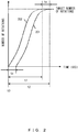
- FIG. 2 illustrates an example of a state in the sensorless electric motor from when the inverter receives an activation signal from the activation control processor 20 to when a target number of rotations is reached.
- a vertical axis represents the number of rotations of the rotor, and a horizontal axis represents a time.
- a curve 201 represents a change in the number of rotations when the first processing is performed on the electric motor 10 after the inverter 11 receives an activation signal (t0) (a change in the number of rotations in a conventional case).
- a curve 202 represents a change in the number of rotations when the electric supercharger 4 is provided and when the first processing is performed on the electric motor 10 before the inverter 11 receives an activation signal (t0) (a change in the number of rotations when the control according to the embodiments is used).
- FIG. 4 is a diagram for explaining the first processing and second processing.
- Horizontal axes of A to C of FIG. 4 each represent a time, and a vertical axis of A of FIG. 4 represents the number of axial rotations (or it may represent a speed of rotation).
- a vertical axis of B of FIG. 4 represents a holding current (an excitation current), and a vertical axis of C of FIG. 4 represents an airflow rate.
- the first processing is performed to align the magnetic pole of the rotor with a predetermined position with respect to the stator (a time period from T1 to T2).
- the second processing is performed to cause a holding current Ih (a solid line) to be output to the inverter 11, the holding current maintaining the magnetic pole of the rotor at the predetermined position (a time period from T2 to T5).
- the holding current Ih is an excitation current predetermined as a result of an experiment or a simulation, such that the position of the rotor is not shifted due to, for example, (A) or (B).
- activation control processing is started.
- (6) If the second processor 19 performs the processing described in (5), it is possible to prevent a phase shift of the rotor due to (A) or (B), but the holding current Ih (the solid line) needs to flow until an activation signal is received.
- a control is performed that increases or decreases the holding current according to the amount of air taken in by the electric supercharger 4 of the vehicle.
- the inflow of air taken in by the impeller of the compressor 9 connected to the rotor is monitored using, for example, a flowmeter 21, and the holding current is changed according to the intake airflow rate measured by the flowmeter 21.
- a flowmeter 21 information in which an intake airflow rate and a holding current are associated is referred to and the holding current is determined, wherein the information is created in advance as a result of an experiment or a simulation, using the measured intake airflow rate.
- the installation position of the flowmeter 21 is not limited to the position illustrated in FIG. 1 .
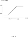
- FIG. 5 illustrates a relationship between an airflow rate and a holding current.
- the information in which an intake airflow rate and a holding current are associated is created on the basis of, for example, the graph illustrated in FIG. 5 .
- a vertical axis in FIG. 5 represents the holding current, and a horizontal axis represents the airflow rate. If the airflow rate is increased, the holding current is increased, and if the airflow rate is reduced, the holding current is decreased.
- the airflow rate is reduced for a time period from T0 to T3. Further, in A and B of FIG. 4 , the first processing was completed at T2. Thus, the information created on the basis of FIG. 5 is referred to and the holding current Ih is increased or decreased until an activation signal is received (a time period from T2 to T5).
- a holding current 201 (a dashed line) illustrated in B of FIG. 4 is controlled, a constant holding current Ih (a solid line) is caused to flow in the processing in (5), but, in the processing in (6), it is possible to increase or decrease the holding current according the intake airflow rate, so power consumption can be reduced.
- an opening and closing control for preventing a phase shift that has been conventionally performed by a valve 22 situated at an intake of the electric supercharger 4 does not have to be performed, so it is possible to increase the life of the valve.
- FIG. 6 is a flowchart that illustrates an example of an operation of the controller.
- Step S1 When it detects, in Step S1, that an ignition switch of a vehicle has been turned on (I/G ON), the controller 5 causes, in Step S2, the second battery 12 to supply power to the inverter 11 so as to energize the inverter 11 (inverter ON).
- Step S2 the processes of Steps S1 and S2 have been completed, the parked vehicle enters a movable state.
- Step S3 the controller 5 causes the inverter 11 to perform a control such that an initial phase alignment of the magnetic pole of the rotor of the electric motor 10 is performed with respect to the stator (the first processing).
- the electric motor 10 is a synchronous motor
- power is supplied to the winding of the stator so as to align the magnetic pole of the rotor with a predetermined position.
- the method for detecting a phase is not limited to this method.
- the second processing is performed.
- the controller 5 causes a holding current to be output to the inverter 11, the holding current maintaining the magnetic pole of the rotor of the electric motor 10 at a position (the predetermined position) with which the magnetic pole is aligned with respect to the stator upon an initial phase alignment.
- Step S4 when the controller 5 detects an activation signal (Yes), the process moves on to Step S5, and when the controller 5 does not detect an activation signal (No), the process waits for an activation signal to be detected in Step S4.
- the activation signal is a signal that is transmitted to the inverter 11 when the activation control processor 20 of the controller 5 detects that the amount of pressing down on the accelerator is not less than a predetermined amount of pressing down on the accelerator.
- Step S5 When an activation signal is detected in Step S4, in Step S5, the controller 5 transmits, to the inverter 11, an instruction including information that causes the number of rotations of the rotor of the electric motor 10 to reach a target number of rotations. After it receives the instruction, the inverter 11 activates the electric motor 10 and causes the number of rotations of the rotor to reach the target number of rotations.
- Step S6 when the controller 5 detects a stop signal (Yes), the process moves on to Step S7, and when the controller 5 does not detect a stop signal (No), the process waits for a stop signal to be detected in Step S6.
- the stop signal is a signal that stops the electric supercharger 4 when the rotor of the electric motor 10 reaches the target number of rotations and the supercharger 3 starts operating effectively.
- Step S7 the controller 5 stops the power supply from the inverter 11 to the electric motor 10. Although the power supply is stopped in Step S7, the rotation of the rotor of the electric motor 10 is not stopped immediately due to inertia but continues (free running).
- Step S8 the controller 5 determines whether a phase estimation can be performed, and when a phase estimation can be performed (Yes), the process moves on to Step S9, and when a phase estimation is not performed (No), the process moves on to Step S3.
- Step S9 when an activation signal is received in a state in which a phase estimation can be performed (Yes), the process moves on to Step S5 and the activation control processor 20 of the controller 5 instructs the inverter 11 to activate the electric motor 10.
- Step S8 When there exists no activation signal in a state in which a phase estimation can be performed (No), the process moves on to Step S8.
- Steps S7 to S9 when the rotor of the electric motor 10 is rotated upon receiving an activation signal and then the number of rotations of the rotor reaches the target number of rotations, the power supply from the inverter 11 to the electric motor 10 is stopped. However, the rotation of the rotor is not stopped immediately due to inertia (free running). However, when the number of rotations of the rotor is not greater than the predetermined number of rotations while free running, it is not possible to perform a phase estimation.
- the inverter 11 monitors an induced voltage of the electric motor 10 to perform a phase estimation of the rotor
- the induced voltage is proportional to the number of rotations, so it is not possible to perform a phase estimation when the number of rotations of the rotor is not greater than the number of rotations that indicates a limit for detecting an induced voltage.
- the inverter 11 delays rotating the rotor of the electric motor 10 by the time period for phase detection (ts).
- the electric motor is a sensorless one, and the control described above is applicable to an electric motor used to reach a target number of rotations in a short time.
Landscapes
- Engineering & Computer Science (AREA)
- Power Engineering (AREA)
- Mechanical Engineering (AREA)
- Transportation (AREA)
- Chemical & Material Sciences (AREA)
- General Engineering & Computer Science (AREA)
- Combustion & Propulsion (AREA)
- Life Sciences & Earth Sciences (AREA)
- Sustainable Development (AREA)
- Sustainable Energy (AREA)
- Computer Hardware Design (AREA)
- Microelectronics & Electronic Packaging (AREA)
- Supercharger (AREA)
- Control Of Motors That Do Not Use Commutators (AREA)
Abstract
Description
- The present invention relates to a sensorless electric motor control device.
- Upon activating an electric motor, a phase of a magnetic pole of a rotor is detected with respect to a stator in order to prevent a loss of synchronization. For a phase detection, a method is known that uses a sensor such as a resolver or a rotary encoder, but a method may be used that activates an electric motor in a sensorless state because the cost is increased and the size is made larger if a sensor such as those mentioned above is used.
- However, when an electric motor is activated in a sensorless state, an inverter that supplies power to the electric motor receives an activation signal, sets the position of a magnetic pole of a rotor at a predetermined position with respect to a stator (phase detection), rotates the rotor after the phase detection is completed, and causes the number of rotations to reach a target number of rotations. Thus, there occurs a problem in which a time period from when an activation signal is received to when the number of rotations of the rotor reaches a target number of rotations becomes longer by a time period that does not contribute to an increase in the number of rotations of the rotor to reach the target number of rotations (a time period needed for a phase detection). Further, the time period needed for a phase detection accounts for a considerable proportion of the time period from when an activation signal is received to when the target number of rotations is reached.
- A control device of an internal combustion engine is known that is not sensorless but performs a phase detection using a Hall sensor, so as to operate an electric motor properly upon operating a supercharger (see, for example, Patent Document 1).
- Patent Document 1: Japanese Laid-open Patent Publication No.
2007-127115 - For example, an object of an electric supercharger that supercharges an internal combustion engine provided in a vehicle until a supercharger that supplies the internal combustion engine starts operating effectively is to speed up the vehicle to reach a target speed quickly. At that time, if it is possible to increase the number of rotations of a rotor of an electric motor provided in the electric supercharger to reach a target number of rotations in a short time, it is possible to speed up the vehicle to reach the target speed quickly. In other words, if it is possible to shorten the time period from when an activation signal that is output to an inverter upon pressing down on the accelerator is received to when the target number of rotations is reached, it is possible to speed up the vehicle to reach the target speed quickly. Thus, it is preferable that the time needed for a phase detection of the rotor, which does not contribute to a speeding up of the vehicle, be reduced.
- It is an object of the present invention to provide a sensorless electric motor control device that completes a phase detection of a rotor before an activation signal is received, so as to shorten a time period from when the activation signal is received to when the rotor reaches a target number of rotations.
- According to an aspect of the present invention, an electric motor control device includes an inverter and a phase detection unit.
- The inverter drives a sensorless electric motor. Before the inverter receives an activation signal that activates the electric motor, the phase detection unit causes the inverter to perform a phase detection that aligns a magnetic pole of a rotor of the electric motor with a predetermined position with respect to a stator.
- According to another aspect of the present invention, when the rotor is rotated upon receiving an activation signal and the number of rotations of the rotor is then not greater than a predetermined number of rotations, the phase detection unit causes the inverter to perform a phase detection.
- According to yet another aspect of the present invention, the electric motor control device includes a phase holding unit that causes, after a phase detection is performed, a holding current to be output to the inverter until an activation signal is received, the holding current maintaining the predetermined position.
- According to yet another aspect of the present invention, the phase holding unit causes the holding current to be increased or decreased according to an amount of measured intake air and causes the holding current to be output to the inverter.
- According to yet another aspect of the present invention, the electric motor control device controls the inverter provided in an electric supercharger and the electric motor.
- According to embodiments, an advantage is provided such that a time period from when an activation signal is received to when a rotor reaches a target number of rotations can be shortened.
-
-
FIG. 1 illustrates an example of a control device provided in a vehicle, which includes an electric supercharger; -
FIG. 2 illustrates an example of a state in a sensorless electric motor from when an inverter receives an activation signal to when a target number of rotations is reached; -
FIG. 3 illustrates an example of a state of a vehicle provided with the electric supercharger that has the sensorless electric motor from when an activation signal is received to when a target speed is reached; -
FIG. 4 is a diagram for explaining first processing and second processing; -
FIG. 5 illustrates a relationship between an airflow rate and a holding current; and -
FIG. 6 is a flowchart that illustrate an example of an operation of a controller. - Embodiments will now be described in detail with reference to the drawings.
-
FIG. 1 illustrates an example of a device provided in a vehicle, which includes an electric supercharger. In this example, an electric motor in an electric supercharger is used for descriptions, but the electric motor is not limited to an electric motor provided in an electric supercharger. - A
device 1 illustrated inFIG. 1 includes, for example, aninternal combustion engine 2, asupercharger 3, anelectric supercharger 4, acontroller 5, analternator 6, afirst battery 7, a DC/DC converter 8, aninverter 11, and asecond battery 12. - The
internal combustion engine 2 is provided with anoutput axis 14, and adrive wheel 15 is coupled to theoutput axis 14 in this example. Thesupercharger 3 is a device that forces air into theinternal combustion engine 2, which increases an output of theinternal combustion engine 2.Pipes - The
electric supercharger 4 is a device that includes acompressor 9 and anelectric motor 10 and forces air into theinternal combustion engine 2, and plays a role in, for example, assisting thesupercharger 3. Power provided to theelectric motor 10 that drives thecompressor 9 is supplied by theinverter 11. Theinverter 11 supplies power to theelectric motor 10 according to an instruction given by thecontroller 5. - The
alternator 6 is coupled to theoutput axis 14, and generates power using a rotational energy (rotational power) of theoutput axis 14, and the generated power is charged in thefirst battery 7 that is a secondary battery. The power generated by thealternator 6 also includes power generated as a brake regeneration. The power generated by thealternator 6 may be supplied to thesecond battery 12 through the DC/DC converter 8. - The
first battery 7 is a secondary battery for supplying power to an auxiliary device or a system provided in a vehicle, and may be, for example, a lead-acid battery. However, thefirst battery 7 is not limited to the lead-acid battery. - The DC/
DC converter 8 converts a voltage output from thefirst battery 7 into a voltage chargeable to thesecond battery 12, and uses the voltage to charge thesecond battery 12 from thefirst battery 7. - The
second battery 12 is an assembled battery having one or more secondary batteries, and is charged with power provided from the DC/DC converter 8. It is preferable that the secondary battery used in thesecond battery 12 be a secondary battery, such as a lithium-ion battery, that can be charged and discharged in a short time. The secondary battery is not limited to the lithium-ion battery, and a storage element such as a nickel-metal hydride battery (Ni-MH), a lead-acid battery, and a capacitor may be used. Further, thesecond battery 12 may be included in, for example, a battery pack. - In the device of this example, power is supplied from the
second battery 12 to theelectric motor 10 though theinverter 11, but in a device that does not include thesecond battery 12, power for driving theelectric motor 10 may be supplied from thefirst battery 7 to theinverter 11 through the DC/DC converter 8. - The
controller 5 may be a circuit that uses, for example, a CPU (central processing unit), a multicore CPU, or a programmable device (such as an FPGA (field programmable gate array) and PLD (programmable logic device)), and thecontroller 5 reads a program that controls each unit and is stored in a storage provided inside or outside thecontroller 5, and executes the program. In this example, thecontroller 5 is used for descriptions, but the control performed by thecontroller 5 may be performed by one or more electronic control units (ECU) provided in a vehicle or one or more battery ECUs in a battery pack. The storage is, for example, a memory such as a read only memory (ROM) and a random access memory (RAM), and it may store therein data such as a parameter value and a variable value, or it may be used as a working area upon execution. The storage may be provided separately from thecontroller 5. - The
controller 5 includes afirst processor 18, asecond processor 19, and anactivation control processor 20. - The first processor is described.
- The
first processor 18 is a phase detection unit that causes theinverter 11 to perform an initial phase alignment (first processing) of theelectric motor 10 before theinverter 11 receives an activation signal that activates the sensorlesselectric motor 10. The initial phase alignment is processing of aligning a magnetic pole of a rotor with a predetermined position with respect to a stator. -
FIG. 2 illustrates an example of a state in the sensorless electric motor from when the inverter receives an activation signal from theactivation control processor 20 to when a target number of rotations is reached. A vertical axis represents the number of rotations of the rotor, and a horizontal axis represents a time. Acurve 201 represents a change in the number of rotations when the first processing is performed on theelectric motor 10 after theinverter 11 receives an activation signal (t0) (a change in the number of rotations in a conventional case). Acurve 202 represents a change in the number of rotations when theelectric supercharger 4 is provided and when the first processing is performed on theelectric motor 10 before theinverter 11 receives an activation signal (t0) (a change in the number of rotations when the control according to the embodiments is used). - (1) When the sensorless
electric motor 10 is activated, the first processing needs to be performed. When the first processing is started and completed after an activation signal is received (t0) as is conventional, a time period for phase detection (ts) from when the time at which the activation signal is received (t0) to when the first processing is completed is needed, as represented by thecurb 201. The time period for phase detection (ts) is a small amount of time, but is wasted time which does not contribute to a time period (t2) from the time (t0) to when the number of rotations of the rotor reaches a target number of rotations. Further, the time period for phase detection (ts) accounts for a considerable proportion of the time period (t2). Thus, if the first processing is performed before theinverter 11 receives an activation signal (t0) as described above, a time period (t1) from when the activation signal is received (t0) to when the rotor reaches a target number of rotations is shortened (t1=t2-ts). This is represented by thecurve 202.
FIG. 3 illustrates an example of a state of a vehicle provided with an electric supercharger that has the sensorless electric motor from when an activation signal is received from theactivation control processor 20 to when a target speed is reached. A vertical axis represents a vehicle speed, and a horizontal axis represents a time. Acurve 301 represents a change in vehicle speed when an electric supercharger is not provided (a change in vehicle speed when only an internal combustion engine is provided). Acurve 302 represents a change in vehicle speed when theelectric supercharger 4 is provided and when the first processing is performed on theelectric motor 10 after theinverter 11 receives an activation signal (t0) (a change in vehicle speed when an internal combustion engine and an electric supercharger are provided in a conventional case). Acurve 303 represents a change in vehicle speed when theelectric supercharger 4 is provided and when the first processing is performed on theelectric motor 10 before theinverter 11 receives an activation signal (t0) (a change in vehicle speed when an internal combustion engine and an electric supercharger are provided and when the control according to the embodiments is used). - (2) In the case of the
electric supercharger 4 of the vehicle, if the first processing is performed before an activation signal is received (t0) as illustrated inFIG. 3 so as to shorten a time period (t11) from when the activation signal is received (t0) to when the rotor reaches a target number of rotations (t11=t22-ts), it is possible to cause the vehicle speed to reach a target speed earlier than when a conventional control is used. In the case of theelectric supercharger 4 of a conventional vehicle, an activation signal is transmitted to theinverter 11 upon pressing down on the accelerator, the first processing is performed when theinverter 11 receives the activation signal (t0), the rotor of theelectric motor 10 of the vehicle starts rotating, and supercharging from thecompressor 9 to theinternal combustion engine 2 is started. Then, a power supply to theelectric motor 10 is stopped when the vehicle reaches the target speed. It is represented by thecurve 302. As described above, also in the case of theelectric motor 10 of the conventional vehicle, the time period for phase detection (ts) is wasted time which does not contribute to a speeding up to reach the target speed. Thus, if the first processing is completed before an activation signal is transmitted upon pressing down on the accelerator and is received (t0) by theinverter 11, it is possible to eliminate wasted time which does not contribute to a speeding up (t11=t22-ts). It is represented by thecurve 303.
Further, thecontroller 5 determines, using the number of rotations of the rotor that is monitored by theinverter 11, whether the number of rotations of the rotor is not greater than a predetermined number of rotations Nth, and when it is not greater than the predetermined number of rotations Nth, thecontroller 5 forces theinverter 11 to perform the first processing. - (3) When the rotor of the
electric motor 10 is rotated upon receiving an activation signal and then the number of rotations of the rotor reaches a target number of rotations, the power supply from theinverter 11 to the conventionalelectric motor 10 is stopped. However, the rotation of the rotor is not stopped immediately due to inertia but continues (free running). Besides, when the number of rotations of the rotor is not greater than the predetermined number of rotations Nth while free running, it is not possible to perform a phase estimation. For example, when theinverter 11 monitors an induced voltage of theelectric motor 10 to perform a phase estimation of the rotor, the induced voltage is proportional to the number of rotations, so it is not possible to perform a phase estimation when the number of rotations of the rotor is not greater than the predetermined number of rotations Nth that indicates a limit for detecting an induced voltage. At this point, if the first processing is performed after a new activation signal is received as is conventional, theinverter 11 delays rotating the rotor of theelectric motor 10 by the time period for phase detection (ts). Thus, if the first processing is forcibly performed when the number of rotations of the rotor is not greater than the predetermined number of rotations Nth, this results in shortening a time period from when an activation signal is received (t0) to when the rotor reaches the target number of rotations. The predetermined number of rotations is, for example, the number of rotations that indicates a limit for detecting an induced voltage. - (4) Also in the case of the
electric supercharger 4 of the vehicle, if the first processing is forcibly performed when the number of rotations of the rotor is not greater than the predetermined number of rotations Nth and if the first processing is completed before an activation signal is transmitted from theactivation control processor 20 to theinverter 11 upon pressing down on the accelerator, this results in shortening a time period from when the activation signal is received (t0) to when the rotor reaches a target number of rotations. It is not possible to perform a phase estimation when the number of rotations of the rotor of theelectric motor 10 of the vehicle is not greater than the predetermined number of rotations Nth that indicates a limit for detecting an induced voltage. At this point, if the accelerator is pressed down and the first processing is performed after a new activation signal is received (t0), theinverter 11 delays rotating the rotor of theelectric motor 10 by the time period for phase detection (ts), as is conventional. As a result, the vehicle delays increasing its speed to reach a target speed due to the time period for phase detection (ts). Thus, if the first processing is forcibly performed when the number of rotations of the rotor is not greater than the predetermined number of rotations Nth, this results in shortening a time period from when an activation signal is received (t0) to when the vehicle reaches a target speed.
The second processor is described.
Even when an initial phase alignment of the rotor is performed by thefirst processor 18, a phase shift may occur again (A) because the rotor is rotated due to intake air flowing into an impeller of thecompressor 9 connected to the rotor, or (B) because the rotor is rotated due to a disturbance such as vibration. Thus, from when an initial phase alignment has been completed to when an activation signal is received, thesecond processor 19 causes a holding current to be output to theinverter 11, the holding current maintaining the magnetic pole of the rotor of theelectric motor 10 at a position (predetermined position) with which the magnetic pole is aligned with respect to the stator upon the initial phase alignment. In other words, microcurrent that maintains a phase is applied constantly, so as to prevent a phase shift of the rotor due to intake air or a disturbance. Thesecond processor 19 serves as a phase holding unit. - (5) From when an initial phase alignment of the rotor has been completed by the first processor 18 (the first processing) to when an activation signal is received from the
activation control processor 20, thesecond processor 19 causes a holding current to be output to theinverter 11 so that the rotor will not be rotated due to (A) or (B), the holding current maintaining the magnetic pole of the rotor at the predetermined position. This holding current permits preventing of a phase shift of the rotor due to, for example, (A) or (B). -
FIG. 4 is a diagram for explaining the first processing and second processing. Horizontal axes of A to C ofFIG. 4 each represent a time, and a vertical axis of A ofFIG. 4 represents the number of axial rotations (or it may represent a speed of rotation). A vertical axis of B ofFIG. 4 represents a holding current (an excitation current), and a vertical axis of C ofFIG. 4 represents an airflow rate. - When a vehicle reduces its speed as illustrated in A of
FIG. 4 and the number of axial rotations N is equal to the predetermined number of rotations Nth that indicates a limit for detecting an induced voltage (T1), the first processing is performed to align the magnetic pole of the rotor with a predetermined position with respect to the stator (a time period from T1 to T2). When the first processing has been completed (T2), the second processing is performed to cause a holding current Ih (a solid line) to be output to theinverter 11, the holding current maintaining the magnetic pole of the rotor at the predetermined position (a time period from T2 to T5). The holding current Ih is an excitation current predetermined as a result of an experiment or a simulation, such that the position of the rotor is not shifted due to, for example, (A) or (B). When theinverter 11 receives an activation signal (T5), activation control processing is started. (6) If thesecond processor 19 performs the processing described in (5), it is possible to prevent a phase shift of the rotor due to (A) or (B), but the holding current Ih (the solid line) needs to flow until an activation signal is received. Thus, in order to reduce power consumption due to the holding current, a control is performed that increases or decreases the holding current according to the amount of air taken in by theelectric supercharger 4 of the vehicle. In other words, the inflow of air taken in by the impeller of thecompressor 9 connected to the rotor (described above by (A)) is monitored using, for example, aflowmeter 21, and the holding current is changed according to the intake airflow rate measured by theflowmeter 21. For example, information in which an intake airflow rate and a holding current are associated is referred to and the holding current is determined, wherein the information is created in advance as a result of an experiment or a simulation, using the measured intake airflow rate. The installation position of theflowmeter 21 is not limited to the position illustrated inFIG. 1 . -
FIG. 5 illustrates a relationship between an airflow rate and a holding current. The information in which an intake airflow rate and a holding current are associated is created on the basis of, for example, the graph illustrated inFIG. 5 . A vertical axis inFIG. 5 represents the holding current, and a horizontal axis represents the airflow rate. If the airflow rate is increased, the holding current is increased, and if the airflow rate is reduced, the holding current is decreased. - In C of
FIG. 4 , the airflow rate is reduced for a time period from T0 to T3. Further, in A and B ofFIG. 4 , the first processing was completed at T2. Thus, the information created on the basis ofFIG. 5 is referred to and the holding current Ih is increased or decreased until an activation signal is received (a time period from T2 to T5). In other words, if a holding current 201 (a dashed line) illustrated in B ofFIG. 4 is controlled, a constant holding current Ih (a solid line) is caused to flow in the processing in (5), but, in the processing in (6), it is possible to increase or decrease the holding current according the intake airflow rate, so power consumption can be reduced. - Further, an opening and closing control for preventing a phase shift that has been conventionally performed by a
valve 22 situated at an intake of theelectric supercharger 4 does not have to be performed, so it is possible to increase the life of the valve. - Further, it is also possible to suppress the rotation of the impeller, so it is possible to increase the lives of bearings used for axes that are provided in the
compressor 9 and theelectric motor 10 of theelectric supercharger 4. - A control of the inverter that is performed by the
controller 5 is described. -
FIG. 6 is a flowchart that illustrates an example of an operation of the controller. - When it detects, in Step S1, that an ignition switch of a vehicle has been turned on (I/G ON), the
controller 5 causes, in Step S2, thesecond battery 12 to supply power to theinverter 11 so as to energize the inverter 11 (inverter ON). When the processes of Steps S1 and S2 have been completed, the parked vehicle enters a movable state. - In Step S3, the
controller 5 causes theinverter 11 to perform a control such that an initial phase alignment of the magnetic pole of the rotor of theelectric motor 10 is performed with respect to the stator (the first processing). For example, when theelectric motor 10 is a synchronous motor, power is supplied to the winding of the stator so as to align the magnetic pole of the rotor with a predetermined position. However, the method for detecting a phase is not limited to this method. After the first processing is performed, the second processing is performed. In the second processing, from when the first processing has been completed to when an activation signal is received, thecontroller 5 causes a holding current to be output to theinverter 11, the holding current maintaining the magnetic pole of the rotor of theelectric motor 10 at a position (the predetermined position) with which the magnetic pole is aligned with respect to the stator upon an initial phase alignment. - In Step S4, when the
controller 5 detects an activation signal (Yes), the process moves on to Step S5, and when thecontroller 5 does not detect an activation signal (No), the process waits for an activation signal to be detected in Step S4. For example, in the case of theelectric motor 10 provided to theelectric supercharger 4 of the vehicle, the activation signal is a signal that is transmitted to theinverter 11 when theactivation control processor 20 of thecontroller 5 detects that the amount of pressing down on the accelerator is not less than a predetermined amount of pressing down on the accelerator. - When an activation signal is detected in Step S4, in Step S5, the
controller 5 transmits, to theinverter 11, an instruction including information that causes the number of rotations of the rotor of theelectric motor 10 to reach a target number of rotations. After it receives the instruction, theinverter 11 activates theelectric motor 10 and causes the number of rotations of the rotor to reach the target number of rotations. - In Step S6, when the
controller 5 detects a stop signal (Yes), the process moves on to Step S7, and when thecontroller 5 does not detect a stop signal (No), the process waits for a stop signal to be detected in Step S6. For example, the stop signal is a signal that stops theelectric supercharger 4 when the rotor of theelectric motor 10 reaches the target number of rotations and thesupercharger 3 starts operating effectively. - In Step S7, the
controller 5 stops the power supply from theinverter 11 to theelectric motor 10. Although the power supply is stopped in Step S7, the rotation of the rotor of theelectric motor 10 is not stopped immediately due to inertia but continues (free running). - In Step S8, the
controller 5 determines whether a phase estimation can be performed, and when a phase estimation can be performed (Yes), the process moves on to Step S9, and when a phase estimation is not performed (No), the process moves on to Step S3. - In Step S9, when an activation signal is received in a state in which a phase estimation can be performed (Yes), the process moves on to Step S5 and the
activation control processor 20 of thecontroller 5 instructs theinverter 11 to activate theelectric motor 10. When there exists no activation signal in a state in which a phase estimation can be performed (No), the process moves on to Step S8. - In Steps S7 to S9, when the rotor of the
electric motor 10 is rotated upon receiving an activation signal and then the number of rotations of the rotor reaches the target number of rotations, the power supply from theinverter 11 to theelectric motor 10 is stopped. However, the rotation of the rotor is not stopped immediately due to inertia (free running). However, when the number of rotations of the rotor is not greater than the predetermined number of rotations while free running, it is not possible to perform a phase estimation. For example, when theinverter 11 monitors an induced voltage of theelectric motor 10 to perform a phase estimation of the rotor, the induced voltage is proportional to the number of rotations, so it is not possible to perform a phase estimation when the number of rotations of the rotor is not greater than the number of rotations that indicates a limit for detecting an induced voltage. At this point, if a phase detection is performed after a new activation signal is received (t0) as is conventional, theinverter 11 delays rotating the rotor of theelectric motor 10 by the time period for phase detection (ts). Thus, if a phase detection is forcibly performed when the number of rotations of the rotor is not greater than the predetermined number of rotations Nth, this results in shortening a time period from when an activation signal is received (t0) to when the rotor reaches the target number of rotations. - It is sufficient if the electric motor is a sensorless one, and the control described above is applicable to an electric motor used to reach a target number of rotations in a short time.
- The present invention is not limited to the embodiments described above, and various modifications and alterations may be made thereto without departing from the spirit and scope of the invention.
-
- 1
- device
- 2
- internal combustion engine
- 3
- supercharger
- 4
- electric supercharger
- 5
- controller
- 6
- alternator
- 7
- first battery
- 8
- DC/DC converter
- 9
- compressor
- 10
- electric motor
- 11
- inverter
- 12
- second battery
- 14
- output axis
- 15
- drive wheel
- 16,17
- pipe
- 18
- first processing
- 19
- second processing
- 20
- activation control processor
- 21
- flowmeter
- 22
- valve
Claims (5)
- An electric motor control device comprising:an inverter configured to drive a sensorless electric motor; anda phase detection unit configured to cause the inverter to perform a phase detection before the inverter receives an activation signal that activates the electric motor, wherein the phase detection aligns a magnetic pole of a rotor of the electric motor with a predetermined position with respect to a stator.
- The electric motor control device according to claim 1, wherein
when the rotor is rotated upon receiving the activation signal and the number of rotations of the rotor is then not greater than a predetermined number of rotations, the phase detection unit causes the inverter to perform the phase detection. - The electric motor control device according to claim 1 or 2, comprising
a phase holding unit configured to cause, after the phase detection is performed, a holding current to be output to the inverter until the activation signal is received, the holding current holding the predetermined position. - The electric motor control device according to claim 3, wherein
the phase holding unit causes the holding current to be increased or decreased according to an amount of measured intake air and causes the holding current to be output to the inverter. - The electric motor control device according to any one of claims 1 to 4, wherein
the control device controls the inverter provided in an electric supercharger and the electric motor.
Applications Claiming Priority (3)
| Application Number | Priority Date | Filing Date | Title |
|---|---|---|---|
| JP2014068849 | 2014-03-28 | ||
| JP2014182869 | 2014-09-09 | ||
| PCT/JP2015/053973 WO2015146350A1 (en) | 2014-03-28 | 2015-02-13 | Electric motor control device |
Publications (2)
| Publication Number | Publication Date |
|---|---|
| EP3125423A1 true EP3125423A1 (en) | 2017-02-01 |
| EP3125423A4 EP3125423A4 (en) | 2017-11-29 |
Family
ID=54194888
Family Applications (1)
| Application Number | Title | Priority Date | Filing Date |
|---|---|---|---|
| EP15768361.6A Withdrawn EP3125423A4 (en) | 2014-03-28 | 2015-02-13 | Electric motor control device |
Country Status (4)
| Country | Link |
|---|---|
| US (1) | US9973122B2 (en) |
| EP (1) | EP3125423A4 (en) |
| JP (1) | JP6160768B2 (en) |
| WO (1) | WO2015146350A1 (en) |
Families Citing this family (2)
| Publication number | Priority date | Publication date | Assignee | Title |
|---|---|---|---|---|
| JP6269330B2 (en) * | 2014-06-06 | 2018-01-31 | トヨタ自動車株式会社 | Control device for internal combustion engine |
| KR102516569B1 (en) * | 2017-11-03 | 2023-04-03 | 현대자동차주식회사 | Vehicle and controlling method thereof |
Family Cites Families (13)
| Publication number | Priority date | Publication date | Assignee | Title |
|---|---|---|---|---|
| JPH04275093A (en) | 1991-02-28 | 1992-09-30 | Sony Corp | Brushless motor driving circuit |
| JPH0787785A (en) * | 1993-06-29 | 1995-03-31 | Fujitsu General Ltd | Brushless motor control method and apparatus |
| JPH08266088A (en) * | 1995-03-27 | 1996-10-11 | Nippondenso Co Ltd | Controller for motor |
| JPH11318096A (en) | 1998-04-30 | 1999-11-16 | Seiko Seiki Co Ltd | Driver of brushless motor |
| JP3688273B2 (en) | 2003-02-06 | 2005-08-24 | トヨタ自動車株式会社 | Rotational drive control device for electric motor |
| JP2006271179A (en) * | 2005-02-23 | 2006-10-05 | Mitsubishi Heavy Ind Ltd | Motor control unit and motor control method |
| JP4735427B2 (en) | 2005-10-07 | 2011-07-27 | トヨタ自動車株式会社 | Control device for internal combustion engine |
| US7723931B2 (en) | 2006-05-31 | 2010-05-25 | Pratt & Whitney Canada Corp. | Starting a gas turbine engine using a sensorless, brushless motor |
| US7786687B2 (en) * | 2008-04-25 | 2010-08-31 | Gm Global Technology Operations, Inc. | Apparatus and method for control of an active front steering (AFS) system |
| US8294397B2 (en) * | 2010-03-17 | 2012-10-23 | Sunonwealth Electronic Machine Industry Co., Ltd. | Sensorless starting control method for a BLDC motor |
| JP2012249355A (en) * | 2011-05-25 | 2012-12-13 | Hitachi Appliances Inc | Motor controller and motor starting method using the same |
| JP6026812B2 (en) | 2012-08-10 | 2016-11-16 | 日立オートモティブシステムズ株式会社 | Motor control device including motor unit and inverter unit |
| JP5724977B2 (en) | 2012-09-20 | 2015-05-27 | 株式会社デンソー | Brushless motor control system |
-
2015
- 2015-02-13 JP JP2016510113A patent/JP6160768B2/en not_active Expired - Fee Related
- 2015-02-13 US US15/129,688 patent/US9973122B2/en active Active
- 2015-02-13 WO PCT/JP2015/053973 patent/WO2015146350A1/en not_active Ceased
- 2015-02-13 EP EP15768361.6A patent/EP3125423A4/en not_active Withdrawn
Also Published As
| Publication number | Publication date |
|---|---|
| US20170133963A1 (en) | 2017-05-11 |
| JPWO2015146350A1 (en) | 2017-04-13 |
| EP3125423A4 (en) | 2017-11-29 |
| WO2015146350A1 (en) | 2015-10-01 |
| JP6160768B2 (en) | 2017-07-12 |
| US9973122B2 (en) | 2018-05-15 |
Similar Documents
| Publication | Publication Date | Title |
|---|---|---|
| JP5720620B2 (en) | vehicle | |
| US8292778B2 (en) | Idle-stop restart control system | |
| JP6186248B2 (en) | Inverter abnormality determination device | |
| JP2016133030A (en) | Power control device | |
| WO2021197478A1 (en) | Vehicle, and method and apparatus for heating battery pack thereof | |
| US9973122B2 (en) | Electric motor control device | |
| CN102195441A (en) | Electromagnetic type retarder | |
| US20220056876A1 (en) | Vehicle controlling apparatus | |
| US10907628B2 (en) | Electric compressor | |
| CN103684142A (en) | Control system used for brushless electric machine | |
| EP2789494B1 (en) | Battery charging apparatus for vehicle | |
| KR20180068463A (en) | Hybrid Vehicle And Method For Start Controlling Of Hybrid Vehicle | |
| CN114483336B (en) | Engine rotation control method, engine rotation control device, motorcycle and storage medium | |
| US10351142B2 (en) | Hybrid vehicle | |
| JP2008238856A (en) | Control device for motor generator | |
| WO2013171843A1 (en) | Field winding rotating electrical machine and method for controlling field current of a field winding rotating electrical machine | |
| JP6617653B2 (en) | Power supply | |
| JP5950017B2 (en) | Control device for electric motor for vehicle | |
| US20200180420A1 (en) | Hybrid vehicle | |
| JP2008283840A (en) | Power system, control method therefor, and vehicle | |
| CN110422159A (en) | The method and apparatus of controlled stopping for internal combustion engine | |
| JP7310576B2 (en) | vehicle controller | |
| US20170305414A1 (en) | Hybrid vehicle | |
| JP5853707B2 (en) | Charger | |
| US9637025B2 (en) | Control apparatus for vehicle motor |
Legal Events
| Date | Code | Title | Description |
|---|---|---|---|
| STAA | Information on the status of an ep patent application or granted ep patent |
Free format text: STATUS: THE INTERNATIONAL PUBLICATION HAS BEEN MADE |
|
| PUAI | Public reference made under article 153(3) epc to a published international application that has entered the european phase |
Free format text: ORIGINAL CODE: 0009012 |
|
| STAA | Information on the status of an ep patent application or granted ep patent |
Free format text: STATUS: REQUEST FOR EXAMINATION WAS MADE |
|
| 17P | Request for examination filed |
Effective date: 20160928 |
|
| AK | Designated contracting states |
Kind code of ref document: A1 Designated state(s): AL AT BE BG CH CY CZ DE DK EE ES FI FR GB GR HR HU IE IS IT LI LT LU LV MC MK MT NL NO PL PT RO RS SE SI SK SM TR |
|
| AX | Request for extension of the european patent |
Extension state: BA ME |
|
| DAX | Request for extension of the european patent (deleted) | ||
| A4 | Supplementary search report drawn up and despatched |
Effective date: 20171102 |
|
| RIC1 | Information provided on ipc code assigned before grant |
Ipc: H02P 6/182 20160101ALI20171025BHEP Ipc: H02P 1/02 20060101ALI20171025BHEP Ipc: H02P 6/20 20160101ALI20171025BHEP Ipc: H02P 6/18 20160101AFI20171025BHEP |
|
| STAA | Information on the status of an ep patent application or granted ep patent |
Free format text: STATUS: EXAMINATION IS IN PROGRESS |
|
| 17Q | First examination report despatched |
Effective date: 20200417 |
|
| STAA | Information on the status of an ep patent application or granted ep patent |
Free format text: STATUS: THE APPLICATION HAS BEEN WITHDRAWN |
|
| 18W | Application withdrawn |
Effective date: 20220930 |