EP3125363A1 - Mobile terminal and nfc antenna - Google Patents
Mobile terminal and nfc antenna Download PDFInfo
- Publication number
- EP3125363A1 EP3125363A1 EP14887036.3A EP14887036A EP3125363A1 EP 3125363 A1 EP3125363 A1 EP 3125363A1 EP 14887036 A EP14887036 A EP 14887036A EP 3125363 A1 EP3125363 A1 EP 3125363A1
- Authority
- EP
- European Patent Office
- Prior art keywords
- coil
- centerline
- longitudinal centerline
- mobile terminal
- substrate
- Prior art date
- Legal status (The legal status is an assumption and is not a legal conclusion. Google has not performed a legal analysis and makes no representation as to the accuracy of the status listed.)
- Withdrawn
Links
- 238000004891 communication Methods 0.000 claims abstract description 83
- 239000000758 substrate Substances 0.000 claims description 62
- 230000006855 networking Effects 0.000 abstract description 23
- 230000035945 sensitivity Effects 0.000 abstract description 14
- 238000005452 bending Methods 0.000 description 21
- 230000003247 decreasing effect Effects 0.000 description 15
- 230000007423 decrease Effects 0.000 description 12
- 230000003993 interaction Effects 0.000 description 3
- 230000008901 benefit Effects 0.000 description 2
- 239000000463 material Substances 0.000 description 2
- 230000015572 biosynthetic process Effects 0.000 description 1
- 239000011810 insulating material Substances 0.000 description 1
- 238000012986 modification Methods 0.000 description 1
- 230000004048 modification Effects 0.000 description 1
Images







Classifications
-
- H—ELECTRICITY
- H04—ELECTRIC COMMUNICATION TECHNIQUE
- H04B—TRANSMISSION
- H04B5/00—Near-field transmission systems, e.g. inductive or capacitive transmission systems
- H04B5/20—Near-field transmission systems, e.g. inductive or capacitive transmission systems characterised by the transmission technique; characterised by the transmission medium
- H04B5/24—Inductive coupling
- H04B5/26—Inductive coupling using coils
-
- H—ELECTRICITY
- H01—ELECTRIC ELEMENTS
- H01Q—ANTENNAS, i.e. RADIO AERIALS
- H01Q1/00—Details of, or arrangements associated with, antennas
- H01Q1/12—Supports; Mounting means
- H01Q1/22—Supports; Mounting means by structural association with other equipment or articles
- H01Q1/24—Supports; Mounting means by structural association with other equipment or articles with receiving set
-
- H—ELECTRICITY
- H01—ELECTRIC ELEMENTS
- H01Q—ANTENNAS, i.e. RADIO AERIALS
- H01Q1/00—Details of, or arrangements associated with, antennas
- H01Q1/12—Supports; Mounting means
- H01Q1/22—Supports; Mounting means by structural association with other equipment or articles
- H01Q1/24—Supports; Mounting means by structural association with other equipment or articles with receiving set
- H01Q1/241—Supports; Mounting means by structural association with other equipment or articles with receiving set used in mobile communications, e.g. GSM
- H01Q1/242—Supports; Mounting means by structural association with other equipment or articles with receiving set used in mobile communications, e.g. GSM specially adapted for hand-held use
- H01Q1/243—Supports; Mounting means by structural association with other equipment or articles with receiving set used in mobile communications, e.g. GSM specially adapted for hand-held use with built-in antennas
-
- H—ELECTRICITY
- H01—ELECTRIC ELEMENTS
- H01Q—ANTENNAS, i.e. RADIO AERIALS
- H01Q1/00—Details of, or arrangements associated with, antennas
- H01Q1/36—Structural form of radiating elements, e.g. cone, spiral, umbrella; Particular materials used therewith
- H01Q1/38—Structural form of radiating elements, e.g. cone, spiral, umbrella; Particular materials used therewith formed by a conductive layer on an insulating support
-
- H—ELECTRICITY
- H01—ELECTRIC ELEMENTS
- H01Q—ANTENNAS, i.e. RADIO AERIALS
- H01Q1/00—Details of, or arrangements associated with, antennas
- H01Q1/50—Structural association of antennas with earthing switches, lead-in devices or lightning protectors
-
- H—ELECTRICITY
- H01—ELECTRIC ELEMENTS
- H01Q—ANTENNAS, i.e. RADIO AERIALS
- H01Q7/00—Loop antennas with a substantially uniform current distribution around the loop and having a directional radiation pattern in a plane perpendicular to the plane of the loop
-
- H—ELECTRICITY
- H04—ELECTRIC COMMUNICATION TECHNIQUE
- H04W—WIRELESS COMMUNICATION NETWORKS
- H04W4/00—Services specially adapted for wireless communication networks; Facilities therefor
- H04W4/80—Services using short range communication, e.g. near-field communication [NFC], radio-frequency identification [RFID] or low energy communication
Definitions
- the present disclosure relates to the communication field, and more particularly to a mobile terminal and a near field communication antenna.
- a near field communication (NFC) antenna consists of a circuit board and a planar coil.
- P2P peer-to-peer
- the two NFC antennas may interfere with each other, which may cause a large deviation of a resonance frequency, affect a communication sensitivity and success rate, and thus there is a need for improvements.
- interaction between two NFC antennas may decrease with decreasing of a corresponding overlapping area of the two NFC antennas opposed to each other.
- a decrease of the deviation of the resonance frequency is obvious; when the corresponding overlapping area of the two NFC antennas opposed to each other increases, the decrease of the deviation of the resonance frequency trends gently. While the two NFC antennas are staggered to each other completely, the resonance frequency trends stable.
- the NFC antenna is of a symmetric structure, thus two NFC antennas may exactly overlap with each other when two mobile terminals are disposed back to back, thus when these two mobile terminals operate the peer-to-peer networking, a large mutual interference between the two NFC antennas may cause a decrease to the communication sensitivity.
- the present disclosure provides a mobile terminal.
- the mobile terminal shows a smaller deviation of the resonance frequency when operating the peer-to-peer networking, and also shows high communication sensitivity, a high communication success rate, a strong communication capability, etc.
- the mobile terminal includes: a terminal body, including a rear surface defined with a rear longitudinal centerline and a rear transverse centerline; and a near field communication antenna, disposed on the rear surface of the terminal body. At least one of the rear longitudinal centerline and the rear transverse centerline pass through the near field communication antenna, and the near field communication antenna is disposed asymmetrically to the at least one of the rear longitudinal centerline and the rear transverse centerline.
- the NFC antenna is disposed asymmetrically to the at least one of the rear longitudinal centerline and the rear transverse centerline of the terminal body, and at least one of the rear longitudinal centerline and the rear transverse centerline pass through the NFC antenna, thus when two mobile terminals are disposed back to back to operate the peer-to-peer networking, one of the two NFC antennas may have a first part thereof opposed to the other, and a second part thereof staggered from the other.
- the first part of the two NFC antennas may ensure transmitting and receiving of signals
- the second part of the two NFC antennas may decrease the interference between the two NFC antennas and the deviation of the resonance frequency, which may ensure an operating frequency of the NFC antenna within a bandwidth range, and further ensure the communication sensitivity and success rate.
- the mobile terminal shows a lower deviation of the resonance frequency when operating P2P networking, and also shows high communication sensitivity, a high communication success rate, a strong communication capability, etc.
- the near field communication (NFC) antenna includes: a circuit substrate; and a coil, disposed on the circuit substrate, wherein the at least one of the rear longitudinal centerline and the rear transverse centerline pass through the coil, and the coil is disposed asymmetrically to the at least one of the rear longitudinal centerline and the rear transverse centerline.
- the coil is of a quadrilateral ring structure defined with a coil longitudinal centerline, and the coil longitudinal centerline is deviated from the rear longitudinal centerline.
- a ratio of a distance between the coil longitudinal centerline and the rear longitudinal centerline to a ring width of the coil is 1/2.
- the coil is of a quadrilateral ring structure defined with a coil transverse centerline, and the coil transverse centerline is deviated from the rear transverse centerline.
- a ratio of a distance between the coil transverse centerline and the rear transverse centerline to a ring width of the coil is 1/2.
- the coil is of a quadrilateral ring structure, a triangular ring structure or a circular structure.
- the coil is of a quadrilateral ring structure and has a recess adjacent to a corner thereof.
- the recess is of a rectangular structure, and a width of the recess is equal to a ring width of the coil.
- the recess evades an ending of a wire which is wound into the coil.
- two recesses are provided, and the two recesses are disposed adjacent to two opposed corners of the coil respectively.
- the circuit substrate is defined with a substrate longitudinal centerline superposed to the rear longitudinal centerline.
- the circuit substrate is defined with a substrate transverse centerline superposed to the rear transverse centerline.
- the present disclosure further provides a near field communication (NFC) antenna.
- the near field communication (NFC) antenna includes: a circuit substrate, defined with a substrate longitudinal centerline and a substrate transverse centerline; and a coil, disposed on the circuit substrate, wherein at least one of the substrate longitudinal centerline and the substrate transverse centerline pass through the coil, and the coil is disposed asymmetrically to the at least one of the substrate longitudinal centerline and the substrate transverse centerline.
- the NFC antenna is provided by means of the coil being disposed asymmetrically to the at least one of the substrate longitudinal centerline and the substrate transverse centerline, and the at least one of the substrate longitudinal centerline and the substrate transverse centerline passing through the coil.
- one coil of the two NFC antennas may have a third part thereof opposed to the other coil, and a fourth part thereof staggered from the other coil.
- the third part of the coil of the two NFC antennas may ensure transmitting and receiving of signals
- the fourth part of the coil of the two NFC antennas may decrease the interference between the two NFC antennas and the deviation of the resonance frequency, which may ensure the operating frequency of the NFC antenna within the bandwidth range, further ensure the communication sensitivity and success rate.
- the NFC antenna according to embodiments of the present disclosure shows a lower deviation of the resonance frequency when operating P2P networking, and also shows high communication sensitivity, a high communication success rate, a strong communication capability, etc.
- first and second are used herein for purposes of description and are not intended to indicate or imply relative importance or significance or to imply the number of indicated technical features.
- the feature defined with “first” and “second” may comprise one or more of this feature.
- a plurality of means two or more than two, unless specified otherwise.
- the terms “mounted,” “connected,” “coupled,” “fixed” and the like are used broadly, and may be, for example, fixed connections, detachable connections, or integral connections; may also be mechanical or electrical connections; may also be direct connections or indirect connections via intervening structures; may also be inner communications of two elements, which can be understood by those skilled in the art according to specific situations.
- a structure in which a first feature is "on" or “below” a second feature may include an embodiment in which the first feature is in direct contact with the second feature, and may also include an embodiment in which the first feature and the second feature are not in direct contact with each other, but are contacted via an additional feature formed there between.
- a first feature "on,” “above,” or “on top of” a second feature may include an embodiment in which the first feature is right or obliquely “on,” “above,” or “on top of” the second feature, or just means that the first feature is at a height higher than that of the second feature; while a first feature “below,” “under,” or “on bottom of” a second feature may include an embodiment in which the first feature is right or obliquely “below,” “under,” or “on bottom of” the second feature, or just means that the first feature is at a height lower than that of the second feature.
- the inventor of the present disclosure finds that, when two mobile terminals each including a NFC antenna operate P2P networking, the size of the corresponding overlapping area of the two NFC antennas opposed to each other has a significant impact on the communication sensitivity and success rate.
- the interaction between two NFC antennas decreases with the decreasing of the corresponding overlapping area of the two NFC antennas opposed to each other.
- the NFC antenna is of a symmetric structure, the two NFC antennas may exactly overlap with each other when two mobile terminals are disposed back to back, and thus a large interaction between the two NFC antennas occurs that may cause a decrease to communication sensitivity.
- a mobile terminal according to embodiments of the present disclosure will be described below referring to Figs. 1 to 12 .
- the mobile terminal 1000 includes a terminal body 100 and a NFC antenna 1.
- the terminal body 100 includes a rear surface 200.
- the rear surface 200 is defined with a rear longitudinal centerline P1 and a rear transverse centerline P2.
- the NFC antenna 1 is disposed on the rear surface 200 of the terminal body.
- the rear longitudinal centerline P1 of the terminal body passes through the NFC antenna, i.e. a projection of the NFC antenna 1 projected on the rear surface 200 of the terminal body is crossing over the rear longitudinal centerline P1 of the terminal body 100.
- the portions of the NFC antenna 1 disposed on both sides of the rear longitudinal centerline P1 of the terminal body 100 are asymmetric.
- a first portion of the NFC antenna 1 is disposed on a left side of the rear longitudinal centerline P1 of the terminal body 100, and a second portion of the NFC antenna 1 is disposed on a right side of the rear longitudinal centerline P1 of the terminal body 100, a left-right direction is represented by arrow B in Figs. 1 to 12 , and the first portion of the NFC antenna 1 disposed on the left side of the rear longitudinal centerline P1 of the terminal body 100 and the second portion of the NFC antenna 1 disposed on the right side of the rear longitudinal centerline P1 of the terminal body 100 is asymmetric with respect to the rear longitudinal centerline P1 of the terminal body 100, i.e.
- the NFC antenna 1 is asymmetrically disposed with respect to the rear longitudinal centerline P1 of the terminal body 100.
- the rear longitudinal centerline P1 of the terminal body 100 refers to an imaginary line oriented in an upper-lower direction and disposed at the center of the rear surface 200 of the terminal body 100 in the left-right direction, and the upper-lower direction is represented by arrow A in Figs. 1 to 12 .
- the rear transverse centerline P2 of the terminal body 100 may also pass through the NFC antenna 1, and the NFC antenna 1 is asymmetrically disposed with respect to the rear transverse centerline P2 of the terminal body 100.
- the rear transverse centerline P2 of the terminal body 100 refers to an imaginary line oriented in the left-right direction and disposed at the center of the rear surface of the terminal body in the upper-lower direction, and the left-right direction is represented by arrow B in Figs. 1 to 12 .
- the NFC antenna 1 may also pass through both the rear longitudinal centerline P1 and the rear transverse centerline P2 of the terminal body 100, and the NFC antenna 1 is asymmetrically disposed with respect to both the rear longitudinal centerline P1 and the rear transverse centerline P2 of the terminal body 100, thus to achieve the purpose of the present disclosure.
- the mobile terminal 1000 is provided by means of the NFC antenna 1 being disposed asymmetrically to the at least one of the rear longitudinal centerline P1 and the rear transverse centerline P2 of the terminal body 100, and at least one of the rear longitudinal centerline P1 and the rear transverse centerline P2 passing through the NFC antenna 1.
- one of the two NFC antennas 1 may have the first part thereof opposed to the other, and the second part thereof staggered from the other.
- the first part of the two NFC antennas 1 may ensure transmitting and receiving of signals
- the second part of the two NFC antennas 1 may decrease the interference between the two NFC antennas 1 and the deviation of the resonance frequency, which may ensure an operating frequency of the NFC antenna 1 within a bandwidth range, and further improve communication sensitivity and success rate.
- the mobile terminal shows a lower deviation of the resonance frequency when operating P2P networking, and also shows high communication sensitivity, a high communication success rate, a strong communication capability, etc.
- the mobile terminal 1000 is mobile phone.
- the mobile terminal 1000 according to specific embodiments of the present disclosure will be described below by way of an example that the NFC antenna 1 is asymmetrically disposed with respect to the rear longitudinal centerline P1 of the terminal body 100.
- the NFC antenna 1 includes a circuit substrate 10 and a coil 20.
- the circuit substrate 10 is known to one skilled in the related art, which is made of an insulating material.
- the coil 20 is disposed on the circuit substrate 10, the rear longitudinal centerline P1 of the terminal body pass through the coil 20, and both portions of the coil 20 disposed on both sides of the rear longitudinal centerline P1 are asymmetric.
- the circuit substrate 10 may be symmetric with respect to the rear longitudinal centerline P1 of the terminal body 100, or may be asymmetric with respect to the rear longitudinal centerline P1 of the terminal body 100, as long as the coil 20 is symmetric with respect to the rear longitudinal centerline P1 of the terminal body 100.
- the coil 20 may be of a quadrilateral ring structure, a triangular ring structure, a circular structure or any other structure.
- the NFC antenna 1 according to the present disclosure will be described by an example that the coil 20 is of a quadrilateral ring structure.
- the coil 20 may be symmetric with respect to a coil longitudinal centerline L thereof, and the coil longitudinal centerline L deviates from the rear longitudinal centerline P1 of the terminal body 100.
- a coil 20 of a first NFC antenna 1 may have the first part opposed to a coil 20' of a second NFC antenna 1, and the second part staggered from the coil 20' of the second NFC antenna 1. Thereby, with the near field wireless communication being achieved, the mutual interference between two NFC antennas 1 is also decreased.
- a larger symmetrical area of the NFC antenna 1 results in a stronger capacity of receiving signals and a smaller symmetrical area of the NFC antenna 1 results in less deviation of the resonance frequency.
- a percentage of an asymmetrical portion of NFC antenna 1 may be limited.
- a ratio of a distance between the coil longitudinal centerline L and the rear longitudinal centerline P1 of the terminal body 100 to a ring width of the coil 20 is 1/2.
- a distance between a left edge and a right edge of the coil 20 is equal to the ring width of the coil.
- a distance represented by X is equal to the ring width of the coil 20.
- an effective working area of the NFC antenna 1 may be optimized to increase the capability of transmitting and receiving magnetic energy, and the mutual interference of the NFC antenna 1 when operating P2P networking may be also decreased to further decrease the deviation of the resonance frequency and ensure the operating frequency within the bandwidth range. While the communication success rate is optimized, the wireless communication of the NFC antenna 1 can be achieved at a maximum distance range.
- the NFC antenna 1 has a size of 50 * 40 mm, the ring width of coil 20 of the NFC antenna 1 is 8 mm.
- the working mode of two mobile terminals is set into the P2P communication mode, and the two mobile terminals are placed back to back until being completely overlapped by a conventional operating manner, if the communication between the two mobile terminals is completed, success is recorded; if the communication between the two mobile terminals is uncompleted, failure is recorded. After 10 iterations of the test, a statistic is determined such as the communication success rate being 30%.
- the two mobile terminals are pulled apart from each other to increase the relative distance, and a maximum distance for communication between the two mobile terminals of 30 mm is obtained from the test.
- the value of X is increasing from 0, the deviation of the resonance frequency is decreasing, and the distance for communication is also decreasing.
- the working mode of two mobile terminals is set into the P2P communication mode, and the two mobile terminals are placed back to back until being completely overlapped by a conventional operating manner. After 10 times of above test, a statistic showing that the communication success rate is 100% is obtained. Then the two mobile terminals are pulled apart from each other to increase the relative distance, it is obtained from the test that the maximum distance for communication between the two mobile terminals is 25 mm.
- an optimum designed value of X is 8 ⁇ 3 mm.
- the coil longitudinal centerline L may be overlapped with the rear longitudinal centerline P1 of the terminal body 100, and the coil 20 may be asymmetric with respect to the coil longitudinal centerline L thereof.
- the coil 20 has a recess 21 disposed on an upper right portion of the coil 20, dented towards the center of the coil 20, and adjacent to an upper right corner of the coil 20.
- the recess 21 is of a rectangular structure orientated in the left-right direction.
- the rectangular recess 21 has a long side parallel to an upper edge of the coil 20 and a short side parallel to the right edge of the coil 20.
- the upper edge of the coil 20 is provided with a bending portion bending downwards in a direction extending from left to right.
- the bending portion is adjoined to the rear longitudinal centerline P1 of the terminal body, and disposed before the rear longitudinal centerline P1 of the terminal body 100.
- the recess 21 may evade an ending of a wire which is wound into the coil.
- a width of the recess 21 is equal to the ring width of the coil 20.
- a width of the recess 21 in the upper-lower direction referring to a distance represented by Y as shown in Fig. 3
- a length of the recess 21, referring to a distance represented by X as shown in Fig. 3 is equal to a half of a length of the coil 20 in the left-right direction.
- the ring width of coil 20 of the NFC antenna 1 is 4 mm.
- the working mode of two mobile terminals is set into the P2P communication mode, and the two mobile terminals are placed back to back until being completely overlapped by a conventional operating manner, if the communication between the two mobile terminals is completed, success is recorded; if the communication between the two mobile terminals is uncompleted, failure is recorded. After 10 iterations of above test, a statistic is obtained showing that the communication success rate is 30%.
- the two mobile terminals are pulled apart from each other to increase the relative distance, and it is obtained from the test that a maximum distance for communication between the two mobile terminals is 30 mm. While the values of X and Y are increasing from 0, the deviation of the resonance frequency is decreasing, and the distance for communication is also decreasing. When the value of X increases until 23 ⁇ 3 mm, and the value of Y increases until 4 ⁇ 3 mm, the working mode of two mobile terminals is set into the P2P communication mode, and the two mobile terminals are placed back to back until being completely overlapped by a conventional operating manner, if the communication between the two mobile terminals is completed, success is recorded; if the communication between the two mobile terminals is uncompleted, failure is recorded.
- the recess 21 may be alternatively provided adjacent to other 3 corners of the coil 20.
- the recess 21 may be formed at a lower right portion of the coil 20 and adjacent to a lower right corner of the coil 20.
- the recess 21 is of a rectangular structure orientated in the left-right direction.
- the rectangular recess 21 has a long side parallel to a lower edge of the coil 20 and a short side parallel to the right edge of the coil 20.
- the width of the recess 21, referring to a distance represented by Y as shown in Fig. 5 is equal to the ring width of the coil 20.
- the length of the recess 21, referring to a distance represented by X as shown in Fig. 5 is equal to a half of a length of the coil 20 in the left-right direction.
- the lower edge of the coil 20 is provided with a bending portion bending upwards in a direction extending from left to right.
- the bending portion is adjoined to the rear longitudinal centerline P1 of the terminal body, and disposed before the rear longitudinal centerline P1 of the terminal body 100.
- the recess 21 may be formed at a lower left portion of the coil 20 and adjacent to a lower left corner of the coil 20.
- the recess 21 is of a rectangular structure orientated in the left-right direction.
- the rectangular recess 21 has a long side parallel to a lower edge of the coil 20 and a short side parallel to the left edge of the coil 20.
- the width of the recess 21, referring to a distance represented by Y as shown in Fig. 7 is equal to the ring width of the coil 20.
- the length of the recess 21, referring to a distance represented by X as shown in Fig. 7 is equal to a half of the length of the coil 20 in the left-right direction.
- the lower edge of the coil 20 is provided with a bending portion bending downwards in a direction extending from left to right.
- the bending portion is adjoined to the rear longitudinal centerline P1 of the terminal body, and disposed behind the rear longitudinal centerline P1 of the terminal body 100.
- two recesses 21 are provided, and the two recesses 21 are disposed adjacent to two opposed corners of the coil 20 respectively.
- a first recess 21 is formed at an upper right portion of the coil 20 and adjacent to an upper right corner of the coil 20.
- the first recess 21 has a long side parallel to an upper edge of the coil 20 and a short side parallel to the right edge of the coil 20.
- a second recess 21 is formed at a lower left portion of the coil 20 and adjacent to a lower left corner of the coil 20.
- the second recess 21 has a long side parallel to a lower edge of the coil 20 and a short side parallel to the left edge of the coil 20.
- Both of the two recesses 21 have a same length, referring to a distance represented by X as shown in Fig.
- Both of the two recesses 21 have a same width, referring to a distance represented by Y as shown in Fig. 9 , equal to the ring width of the coil 20.
- the upper edge of the coil 20 is provided with a first bending portion bending downwards in a direction extending from left to right.
- the first bending portion is adjoined to the rear longitudinal centerline P1 of the terminal body, and disposed before the rear longitudinal centerline P1 of the terminal body 100.
- the lower edge of the coil 20 is provided with a second bending portion bending downwards in a direction extending from left to right.
- the second bending portion is adjoined to the rear longitudinal centerline P1 of the terminal body, and disposed behind the rear longitudinal centerline P1 of the terminal body 100.
- the ring width of coil 20 of the NFC antenna 1 is 4 mm.
- the working mode of two mobile terminals is set into P2P communication mode, and the two mobile terminals are placed back to back until being completely overlapped by a conventional operating manner, if the communication between the two mobile terminals is completed, success is recorded; if the communication between the two mobile terminals is not completed, failure is recorded. After 10 times of above test, a statistic is obtained showing that the communication success rate is 30%.
- a maximum distance for communication between the two mobile terminals is 30 mm. While the values of X and Y are increasing from 0, the deviation of the resonance frequency is decreasing, and the distance for communication is also decreasing.
- the working mode of two mobile terminals is set into P2P communication mode, and the two mobile terminals are placed back to back until being completely overlapped by a conventional operating manner, if the communication between the two mobile terminals is completed, success is recorded; if the communication between the two mobile terminals is not completed, failure is recorded.
- the NFC antenna 1 has a larger asymmetrical area to decrease the deviation of the resonance frequency when operating P2P networking.
- the two rectangular recesses 21 may be oriented in the upper-lower direction. Specifically, a first rectangular recess may be formed at an upper right portion of the coil 20 and adjacent to an upper right corner of the coil 20. The first rectangular recess 21 has a long side parallel to a right edge of the coil 20 and a short side parallel to an upper edge of the coil 20. A second rectangular recess 21 may be formed at a lower left portion of the coil 20 and adjacent to a lower left corner of the coil 20. The second rectangular recess 21 has a long side parallel to a left edge of the coil 20 and a short side parallel to a lower edge of the coil 20.
- Both of the two rectangular recesses 21 have a same length, referring to a distance represented by Y as shown in Fig. 11 , equal to a difference between a half of the length of the coil 20 in the left-right direction and the ring width of the coil 20. Both of the two rectangular recesses 21 have a same width, referring to a distance represented by X as shown in Fig. 11 , equal to the ring width of the coil 20.
- the right edge of the coil 20 is provided with a first bending portion bending rightwards in a direction extending from upper to lower
- the left edge of the coil 20 is provided with a second bending portion bending rightwards in a direction extending from upper to lower.
- a lower surface of the first bending portion is flush with an upper surface of the second bending portion.
- a specific embodiment directed to the NFC antenna 1 being asymmetrically disposed with respect to the rear transverse centerline P2 of the terminal body 100 may refer to the above mentioned embodiments that the NFC antenna 1 is asymmetrically disposed with respect to the rear longitudinal centerline P1 of the terminal body 100.
- a specific embodiment directed to the NFC antenna 1 being asymmetrically disposed with respect to both the rear longitudinal centerline P1 and the rear transverse centerline P2 of the terminal body 100 may be achieved by in combination of above two embodiments.
- the NFC antenna 1 according to embodiments of the present disclosure will be described herein with reference to Figs. 1 to 12 .
- the NFC antenna 1 according to embodiments of the present disclosure includes a coil 20 and a circuit substrate 10.
- the circuit substrate 10 is defined with a substrate longitudinal centerline S1 and a substrate transverse centerline S2.
- the coil 20 is disposed on the circuit substrate 10, at least one of the substrate longitudinal centerline S1 and the substrate transverse centerline S2 pass through the coil 20, and the coil 20 is disposed asymmetrically to the at least one of the substrate longitudinal centerline S1 and the substrate transverse centerline S2.
- the substrate longitudinal centerline S1 may pass through the coil 20, and the coil 20 may be asymmetrically disposed with respect to the substrate longitudinal centerline S1.
- the substrate transverse centerline S2 may also pass through the coil 20, and the coil 20 may be asymmetrically disposed with respect to the substrate transverse centerline S2.
- the substrate longitudinal centerline S1 and the substrate transverse centerline S2 may both pass through the coil 20, and the coil 20 may be asymmetrically disposed with respect to both the substrate longitudinal centerline S1 and the substrate transverse centerline S2.
- the substrate longitudinal centerline S1 may be overlapped with the rear longitudinal centerline P1 of the terminal body 100, or not overlapped with the rear longitudinal centerline P1 of the terminal body 100.
- the substrate transverse centerline S2 may be overlapped with the rear transverse centerline P2 of the terminal body 100, or not overlapped with the rear transverse centerline P2 of the terminal body 100.
- the NFC antenna 1 is provided by means of the coil 20 disposed asymmetrically to the at least one of the substrate longitudinal centerline S1 and the substrate transverse centerline S2, and the at least one of the substrate longitudinal centerline S1 and the substrate transverse centerline S2 passing through the coil 20.
- one coil 20 of the two NFC antennas 1 may have the third part thereof opposed to the other coil, and a fourth part thereof staggered from the other coil.
- the third part of the coil of the two NFC antennas 1 may ensure transmitting and receiving of signals
- the fourth part of the coil of the two NFC antennas 1 may decrease the interference between the two NFC antennas 1 and the deviation of the resonance frequency, which may ensure the operating frequency of the NFC antenna 1 within the bandwidth range, and further ensure the communication sensitivity and success rate.
- the NFC antenna 1 shows a lower deviation of the resonance frequency when operating the P2P networking, and also shows high communication sensitivity, a high communication success rate, a strong communication capability, etc.
Landscapes
- Engineering & Computer Science (AREA)
- Computer Networks & Wireless Communication (AREA)
- Signal Processing (AREA)
- Near-Field Transmission Systems (AREA)
- Support Of Aerials (AREA)
- Details Of Aerials (AREA)
- Transceivers (AREA)
Abstract
Description
- This application claims the benefit of International Patent Application No.
PCT/CN2014/092200, filed November 25, 2014 Chinese Patent Application No. 201410123232.6, filed March 28, 2014 - The present disclosure relates to the communication field, and more particularly to a mobile terminal and a near field communication antenna.
- A near field communication (NFC) antenna consists of a circuit board and a planar coil. When two mobile terminals each including an NFC antenna operate a peer-to-peer (P2P) networking, the two NFC antennas may interfere with each other, which may cause a large deviation of a resonance frequency, affect a communication sensitivity and success rate, and thus there is a need for improvements.
- The present disclosure is provided by the inventor, based on discoveries of the following facts and problems by the inventor.
- Through a plurality of experiments and analysis of test results, the inventor has found that, interaction between two NFC antennas may decrease with decreasing of a corresponding overlapping area of the two NFC antennas opposed to each other. At the beginning of the decreasing of the corresponding overlapping area of the two NFC antennas opposed to each other, a decrease of the deviation of the resonance frequency is obvious; when the corresponding overlapping area of the two NFC antennas opposed to each other increases, the decrease of the deviation of the resonance frequency trends gently. While the two NFC antennas are staggered to each other completely, the resonance frequency trends stable. In the related art, the NFC antenna is of a symmetric structure, thus two NFC antennas may exactly overlap with each other when two mobile terminals are disposed back to back, thus when these two mobile terminals operate the peer-to-peer networking, a large mutual interference between the two NFC antennas may cause a decrease to the communication sensitivity.
- Therefore, the present disclosure provides a mobile terminal. The mobile terminal shows a smaller deviation of the resonance frequency when operating the peer-to-peer networking, and also shows high communication sensitivity, a high communication success rate, a strong communication capability, etc.
- The mobile terminal according to embodiments of the present disclosure includes: a terminal body, including a rear surface defined with a rear longitudinal centerline and a rear transverse centerline; and a near field communication antenna, disposed on the rear surface of the terminal body. At least one of the rear longitudinal centerline and the rear transverse centerline pass through the near field communication antenna, and the near field communication antenna is disposed asymmetrically to the at least one of the rear longitudinal centerline and the rear transverse centerline.
- With the mobile terminal according to embodiments of the present disclosure, the NFC antenna is disposed asymmetrically to the at least one of the rear longitudinal centerline and the rear transverse centerline of the terminal body, and at least one of the rear longitudinal centerline and the rear transverse centerline pass through the NFC antenna, thus when two mobile terminals are disposed back to back to operate the peer-to-peer networking, one of the two NFC antennas may have a first part thereof opposed to the other, and a second part thereof staggered from the other. Therefore, the first part of the two NFC antennas may ensure transmitting and receiving of signals, the second part of the two NFC antennas may decrease the interference between the two NFC antennas and the deviation of the resonance frequency, which may ensure an operating frequency of the NFC antenna within a bandwidth range, and further ensure the communication sensitivity and success rate.
- Thus, the mobile terminal according to embodiments of the present disclosure shows a lower deviation of the resonance frequency when operating P2P networking, and also shows high communication sensitivity, a high communication success rate, a strong communication capability, etc.
- In some embodiments, the near field communication (NFC) antenna includes: a circuit substrate; and a coil, disposed on the circuit substrate, wherein the at least one of the rear longitudinal centerline and the rear transverse centerline pass through the coil, and the coil is disposed asymmetrically to the at least one of the rear longitudinal centerline and the rear transverse centerline.
- In some embodiments, the coil is of a quadrilateral ring structure defined with a coil longitudinal centerline, and the coil longitudinal centerline is deviated from the rear longitudinal centerline.
- In some embodiments, a ratio of a distance between the coil longitudinal centerline and the rear longitudinal centerline to a ring width of the coil is 1/2.
- In some embodiments, the coil is of a quadrilateral ring structure defined with a coil transverse centerline, and the coil transverse centerline is deviated from the rear transverse centerline.
- In some embodiments, a ratio of a distance between the coil transverse centerline and the rear transverse centerline to a ring width of the coil is 1/2.
- In some embodiments, the coil is of a quadrilateral ring structure, a triangular ring structure or a circular structure.
- In some embodiments, the coil is of a quadrilateral ring structure and has a recess adjacent to a corner thereof.
- In some embodiments, the recess is of a rectangular structure, and a width of the recess is equal to a ring width of the coil.
- In some embodiments, the recess evades an ending of a wire which is wound into the coil.
- In some embodiments, two recesses are provided, and the two recesses are disposed adjacent to two opposed corners of the coil respectively.
- In some embodiments, the circuit substrate is defined with a substrate longitudinal centerline superposed to the rear longitudinal centerline.
- In some embodiments, the circuit substrate is defined with a substrate transverse centerline superposed to the rear transverse centerline.
- The present disclosure further provides a near field communication (NFC) antenna. The near field communication (NFC) antenna includes: a circuit substrate, defined with a substrate longitudinal centerline and a substrate transverse centerline; and a coil, disposed on the circuit substrate, wherein at least one of the substrate longitudinal centerline and the substrate transverse centerline pass through the coil, and the coil is disposed asymmetrically to the at least one of the substrate longitudinal centerline and the substrate transverse centerline.
- The NFC antenna according to embodiments of the present disclosure, is provided by means of the coil being disposed asymmetrically to the at least one of the substrate longitudinal centerline and the substrate transverse centerline, and the at least one of the substrate longitudinal centerline and the substrate transverse centerline passing through the coil. Thus when two NFC antennas operate the peer-to-peer networking, one coil of the two NFC antennas may have a third part thereof opposed to the other coil, and a fourth part thereof staggered from the other coil. Therefore, the third part of the coil of the two NFC antennas may ensure transmitting and receiving of signals, the fourth part of the coil of the two NFC antennas may decrease the interference between the two NFC antennas and the deviation of the resonance frequency, which may ensure the operating frequency of the NFC antenna within the bandwidth range, further ensure the communication sensitivity and success rate.
- Thus, the NFC antenna according to embodiments of the present disclosure shows a lower deviation of the resonance frequency when operating P2P networking, and also shows high communication sensitivity, a high communication success rate, a strong communication capability, etc.
-
-
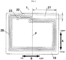
Fig. 1 is a schematic view of a mobile terminal having a NFC antenna according to embodiments of the present disclosure; -
Fig. 2 is a schematic view showing two NFC antennas as shown inFig. 1 opposed to each other when operating the P2P networking; -
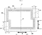
Fig. 3 is schematic view of a NFC antenna of a mobile terminal according to a first embodiment of the present disclosure; -
Fig. 4 is a schematic view showing two NFC antennas as shown inFig. 3 opposed to each other when operating P2P networking; -
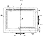
Fig. 5 is schematic view of a NFC antenna of a mobile terminal according to a second embodiment of the present disclosure; -
Fig. 6 is a schematic view showing two NFC antennas as shown inFig. 5 opposed to each other when operating P2P networking; -
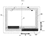
Fig. 7 is schematic view of a NFC antenna of a mobile terminal according to a third embodiment of the present disclosure; -
Fig. 8 is a schematic view showing two NFC antennas as shown inFig. 7 opposed to each other when operating P2P networking; -
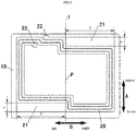
Fig. 9 is schematic view of a NFC antenna of a mobile terminal according to a fourth embodiment of the present disclosure; -
Fig. 10 is a schematic view showing two NFC antennas as shown inFig. 9 opposed to each other when operating P2P networking; -
Fig. 11 is schematic view of a NFC antenna of a mobile terminal according to a fifth embodiment of the present disclosure; -
Fig. 12 is a schematic view showing two NFC antennas as shown inFig. 11 opposed to each other when operating P2P networking; - Reference Numerals:
-
mobile terminal 1000,terminal body 100,rear surface 200 of the terminal body, rear longitudinal centerline P1 of the terminal body, rear transverse centerline P2 of the terminal body; -
NFC antenna 1,circuit substrate 10, substrate longitudinal centerline S1, substrate transverse centerline S2; -
coil 20 of first NFC antenna, coil longitudinal centerline L ofcoil 20,recess 21, ending ofwire 22; - coil 20' of second NFC antenna.
- Reference will be made in detail to embodiments of the present disclosure. The embodiments are described herein with reference to drawings. The same or similar elements and the elements having same or similar functions are denoted by like reference numerals throughout the descriptions. The embodiments described with reference to drawings are explanatory, illustrative, and used to generally understand the present disclosure. The embodiments shall not be construed to limit the present disclosure.
- In the specification, it is to be understood that terms such as "central," "longitudinal," "transverse," "length," "width," "thickness," "upper," "lower," "front," "rear," "left," "right," "vertical," "horizontal," "top," "bottom," "inner," "outer," "clockwise," and "counterclockwise" should be construed to refer to the orientation as then described or as shown in the drawings under discussion. These relative terms are for convenience of description and do not require that the present disclosure be constructed or operated in a particular orientation.
- In addition, terms such as "first" and "second" are used herein for purposes of description and are not intended to indicate or imply relative importance or significance or to imply the number of indicated technical features. Thus, the feature defined with "first" and "second" may comprise one or more of this feature. In the description of the present disclosure, "a plurality of" means two or more than two, unless specified otherwise.
- In the present disclosure, unless specified or limited otherwise, the terms "mounted," "connected," "coupled," "fixed" and the like are used broadly, and may be, for example, fixed connections, detachable connections, or integral connections; may also be mechanical or electrical connections; may also be direct connections or indirect connections via intervening structures; may also be inner communications of two elements, which can be understood by those skilled in the art according to specific situations.
- In the present disclosure, unless specified or limited otherwise, a structure in which a first feature is "on" or "below" a second feature may include an embodiment in which the first feature is in direct contact with the second feature, and may also include an embodiment in which the first feature and the second feature are not in direct contact with each other, but are contacted via an additional feature formed there between. Furthermore, a first feature "on," "above," or "on top of" a second feature may include an embodiment in which the first feature is right or obliquely "on," "above," or "on top of" the second feature, or just means that the first feature is at a height higher than that of the second feature; while a first feature "below," "under," or "on bottom of" a second feature may include an embodiment in which the first feature is right or obliquely "below," "under," or "on bottom of" the second feature, or just means that the first feature is at a height lower than that of the second feature.
- The inventor of the present disclosure finds that, when two mobile terminals each including a NFC antenna operate P2P networking, the size of the corresponding overlapping area of the two NFC antennas opposed to each other has a significant impact on the communication sensitivity and success rate. The interaction between two NFC antennas decreases with the decreasing of the corresponding overlapping area of the two NFC antennas opposed to each other. When the NFC antenna is of a symmetric structure, the two NFC antennas may exactly overlap with each other when two mobile terminals are disposed back to back, and thus a large interaction between the two NFC antennas occurs that may cause a decrease to communication sensitivity.
- A mobile terminal according to embodiments of the present disclosure will be described below referring to
Figs. 1 to 12 . - As shown in
Fig. 1 , the mobile terminal 1000 according to embodiments of the present disclosure includes aterminal body 100 and aNFC antenna 1. - In particular, the
terminal body 100 includes arear surface 200. Therear surface 200 is defined with a rear longitudinal centerline P1 and a rear transverse centerline P2. TheNFC antenna 1 is disposed on therear surface 200 of the terminal body. The rear longitudinal centerline P1 of the terminal body passes through the NFC antenna, i.e. a projection of theNFC antenna 1 projected on therear surface 200 of the terminal body is crossing over the rear longitudinal centerline P1 of theterminal body 100. The portions of theNFC antenna 1 disposed on both sides of the rear longitudinal centerline P1 of theterminal body 100 are asymmetric. In other words, a first portion of theNFC antenna 1 is disposed on a left side of the rear longitudinal centerline P1 of theterminal body 100, and a second portion of theNFC antenna 1 is disposed on a right side of the rear longitudinal centerline P1 of theterminal body 100, a left-right direction is represented by arrow B inFigs. 1 to 12 , and the first portion of theNFC antenna 1 disposed on the left side of the rear longitudinal centerline P1 of theterminal body 100 and the second portion of theNFC antenna 1 disposed on the right side of the rear longitudinal centerline P1 of theterminal body 100 is asymmetric with respect to the rear longitudinal centerline P1 of theterminal body 100, i.e. theNFC antenna 1 is asymmetrically disposed with respect to the rear longitudinal centerline P1 of theterminal body 100. In some embodiments, the rear longitudinal centerline P1 of theterminal body 100 refers to an imaginary line oriented in an upper-lower direction and disposed at the center of therear surface 200 of theterminal body 100 in the left-right direction, and the upper-lower direction is represented by arrow A inFigs. 1 to 12 . - It is to be understood that, according to the
mobile terminal 1000 of embodiments of the present disclosure, the rear transverse centerline P2 of theterminal body 100 may also pass through theNFC antenna 1, and theNFC antenna 1 is asymmetrically disposed with respect to the rear transverse centerline P2 of theterminal body 100. Thereby, twomobile terminals 1000 may be disposed back to back when operating P2P networking. In some embodiments, the rear transverse centerline P2 of theterminal body 100 refers to an imaginary line oriented in the left-right direction and disposed at the center of the rear surface of the terminal body in the upper-lower direction, and the left-right direction is represented by arrow B inFigs. 1 to 12 . - The
NFC antenna 1 may also pass through both the rear longitudinal centerline P1 and the rear transverse centerline P2 of theterminal body 100, and theNFC antenna 1 is asymmetrically disposed with respect to both the rear longitudinal centerline P1 and the rear transverse centerline P2 of theterminal body 100, thus to achieve the purpose of the present disclosure. - The mobile terminal 1000 according to embodiments of the present disclosure, is provided by means of the
NFC antenna 1 being disposed asymmetrically to the at least one of the rear longitudinal centerline P1 and the rear transverse centerline P2 of theterminal body 100, and at least one of the rear longitudinal centerline P1 and the rear transverse centerline P2 passing through theNFC antenna 1. Thus when two mobile terminals are disposed back to back to operate P2P networking, one of the twoNFC antennas 1 may have the first part thereof opposed to the other, and the second part thereof staggered from the other. Therefore, the first part of the twoNFC antennas 1 may ensure transmitting and receiving of signals, the second part of the twoNFC antennas 1 may decrease the interference between the twoNFC antennas 1 and the deviation of the resonance frequency, which may ensure an operating frequency of theNFC antenna 1 within a bandwidth range, and further improve communication sensitivity and success rate. - Thus, the mobile terminal according to embodiments of the present disclosure shows a lower deviation of the resonance frequency when operating P2P networking, and also shows high communication sensitivity, a high communication success rate, a strong communication capability, etc.
- Specifically, in one embodiment, the
mobile terminal 1000 is mobile phone. - The mobile terminal 1000 according to specific embodiments of the present disclosure will be described below by way of an example that the
NFC antenna 1 is asymmetrically disposed with respect to the rear longitudinal centerline P1 of theterminal body 100. - In some embodiments of the present disclosure, as shown in
Figs. 1 to 12 , theNFC antenna 1 includes acircuit substrate 10 and acoil 20. Thecircuit substrate 10 is known to one skilled in the related art, which is made of an insulating material. Thecoil 20 is disposed on thecircuit substrate 10, the rear longitudinal centerline P1 of the terminal body pass through thecoil 20, and both portions of thecoil 20 disposed on both sides of the rear longitudinal centerline P1 are asymmetric. In other words, thecircuit substrate 10 may be symmetric with respect to the rear longitudinal centerline P1 of theterminal body 100, or may be asymmetric with respect to the rear longitudinal centerline P1 of theterminal body 100, as long as thecoil 20 is symmetric with respect to the rear longitudinal centerline P1 of theterminal body 100. - It's to be understood that, the
coil 20 may be of a quadrilateral ring structure, a triangular ring structure, a circular structure or any other structure. For ease of description, theNFC antenna 1 according to the present disclosure will be described by an example that thecoil 20 is of a quadrilateral ring structure. - In some embodiments of the present disclosure, as shown in
Figs. 1 and2 , thecoil 20 may be symmetric with respect to a coil longitudinal centerline L thereof, and the coil longitudinal centerline L deviates from the rear longitudinal centerline P1 of theterminal body 100. When twomobile terminals 1000 operate P2P networking, acoil 20 of afirst NFC antenna 1 may have the first part opposed to a coil 20' of asecond NFC antenna 1, and the second part staggered from the coil 20' of thesecond NFC antenna 1. Thereby, with the near field wireless communication being achieved, the mutual interference between twoNFC antennas 1 is also decreased. - A larger symmetrical area of the
NFC antenna 1 results in a stronger capacity of receiving signals and a smaller symmetrical area of theNFC antenna 1 results in less deviation of the resonance frequency. Thus, to balance both of above mentioned, a percentage of an asymmetrical portion ofNFC antenna 1 may be limited. - As shown in
Fig. 1 , a ratio of a distance between the coil longitudinal centerline L and the rear longitudinal centerline P1 of theterminal body 100 to a ring width of thecoil 20 is 1/2. In one embodiment, the ring width of thecoil 20 refers to a value = (width of each turn of wires * number of turns) + [distance between adjacent two turns of wires * (number of turns - 1)]. In other words, if theNFC antenna 1 was folded along the rear longitudinal centerline P1 of theterminal body 100, a distance between a left edge and a right edge of thecoil 20 is equal to the ring width of the coil. As shown inFig. 1 , a distance represented by X is equal to the ring width of thecoil 20. - Thus, an effective working area of the
NFC antenna 1 may be optimized to increase the capability of transmitting and receiving magnetic energy, and the mutual interference of theNFC antenna 1 when operating P2P networking may be also decreased to further decrease the deviation of the resonance frequency and ensure the operating frequency within the bandwidth range. While the communication success rate is optimized, the wireless communication of theNFC antenna 1 can be achieved at a maximum distance range. - In one embodiment of the present disclosure, as shown in
Fig. 1 , theNFC antenna 1 has a size of 50 * 40 mm, the ring width ofcoil 20 of theNFC antenna 1 is 8 mm. When the value of X is 0, the working mode of two mobile terminals is set into the P2P communication mode, and the two mobile terminals are placed back to back until being completely overlapped by a conventional operating manner, if the communication between the two mobile terminals is completed, success is recorded; if the communication between the two mobile terminals is uncompleted, failure is recorded. After 10 iterations of the test, a statistic is determined such as the communication success rate being 30%. Then the two mobile terminals are pulled apart from each other to increase the relative distance, and a maximum distance for communication between the two mobile terminals of 30 mm is obtained from the test. While the value of X is increasing from 0, the deviation of the resonance frequency is decreasing, and the distance for communication is also decreasing. When the value of X increases until 8 ± 3 mm, the working mode of two mobile terminals is set into the P2P communication mode, and the two mobile terminals are placed back to back until being completely overlapped by a conventional operating manner. After 10 times of above test, a statistic showing that the communication success rate is 100% is obtained. Then the two mobile terminals are pulled apart from each other to increase the relative distance, it is obtained from the test that the maximum distance for communication between the two mobile terminals is 25 mm. Thus, an optimum designed value of X is 8 ± 3 mm. - In some other embodiments of the present disclosure, as shown in
Figs. 3 to 12 , the coil longitudinal centerline L may be overlapped with the rear longitudinal centerline P1 of theterminal body 100, and thecoil 20 may be asymmetric with respect to the coil longitudinal centerline L thereof. - As shown in
Figs. 3 and4 , thecoil 20 has arecess 21 disposed on an upper right portion of thecoil 20, dented towards the center of thecoil 20, and adjacent to an upper right corner of thecoil 20. Therecess 21 is of a rectangular structure orientated in the left-right direction. Therectangular recess 21 has a long side parallel to an upper edge of thecoil 20 and a short side parallel to the right edge of thecoil 20. - In other words, as shown in
Fig. 3 , the upper edge of thecoil 20 is provided with a bending portion bending downwards in a direction extending from left to right. The bending portion is adjoined to the rear longitudinal centerline P1 of the terminal body, and disposed before the rear longitudinal centerline P1 of theterminal body 100. - To facilitate the formation of the recessed 21, the
recess 21 may evade an ending of a wire which is wound into the coil. - Advantageously, a width of the
recess 21 is equal to the ring width of thecoil 20. In other words, a width of therecess 21 in the upper-lower direction, referring to a distance represented by Y as shown inFig. 3 , is equal to the ring width of thecoil 20. A length of therecess 21, referring to a distance represented by X as shown inFig. 3 , is equal to a half of a length of thecoil 20 in the left-right direction. Thus, while the communication success rate is maximally improved, the wireless communication of theNFC antenna 1 can be achieved at a maximum distance range. - In one embodiment of the present disclosure, as shown in
Fig. 3 , by an example that theNFC antenna 1 has a size of 50 * 40 mm, the ring width ofcoil 20 of theNFC antenna 1 is 4 mm. When the value of X is 0, the working mode of two mobile terminals is set into the P2P communication mode, and the two mobile terminals are placed back to back until being completely overlapped by a conventional operating manner, if the communication between the two mobile terminals is completed, success is recorded; if the communication between the two mobile terminals is uncompleted, failure is recorded. After 10 iterations of above test, a statistic is obtained showing that the communication success rate is 30%. Then the two mobile terminals are pulled apart from each other to increase the relative distance, and it is obtained from the test that a maximum distance for communication between the two mobile terminals is 30 mm. While the values of X and Y are increasing from 0, the deviation of the resonance frequency is decreasing, and the distance for communication is also decreasing. When the value of X increases until 23 ± 3 mm, and the value of Y increases until 4 ± 3 mm, the working mode of two mobile terminals is set into the P2P communication mode, and the two mobile terminals are placed back to back until being completely overlapped by a conventional operating manner, if the communication between the two mobile terminals is completed, success is recorded; if the communication between the two mobile terminals is uncompleted, failure is recorded. After 10 iterations of the above test, a statistic is obtained showing that the communication success rate is 80%. Then the two mobile terminals are pulled apart from each other to increase the relative distance, it is obtained from the test that the maximum distance for communication between the two mobile terminals is 25 mm. When the value of X is further increasing, the success rate is decreasing, and the distance for communication is also decreasing. Thus, an optimum designed point is that the value of X is 23 ± 3 mm, the value of Y is 4 ± 3 mm. - The
recess 21 may be alternatively provided adjacent to other 3 corners of thecoil 20. - For an example, as shown in
Figs. 5 and6 , therecess 21 may be formed at a lower right portion of thecoil 20 and adjacent to a lower right corner of thecoil 20. Therecess 21 is of a rectangular structure orientated in the left-right direction. Therectangular recess 21 has a long side parallel to a lower edge of thecoil 20 and a short side parallel to the right edge of thecoil 20. The width of therecess 21, referring to a distance represented by Y as shown inFig. 5 , is equal to the ring width of thecoil 20. The length of therecess 21, referring to a distance represented by X as shown inFig. 5 , is equal to a half of a length of thecoil 20 in the left-right direction. - In other words, as shown in
Fig. 5 , the lower edge of thecoil 20 is provided with a bending portion bending upwards in a direction extending from left to right. The bending portion is adjoined to the rear longitudinal centerline P1 of the terminal body, and disposed before the rear longitudinal centerline P1 of theterminal body 100. - In another embodiment of the present disclosure, as shown in
Figs. 7 and8 , therecess 21 may be formed at a lower left portion of thecoil 20 and adjacent to a lower left corner of thecoil 20. Therecess 21 is of a rectangular structure orientated in the left-right direction. Therectangular recess 21 has a long side parallel to a lower edge of thecoil 20 and a short side parallel to the left edge of thecoil 20. The width of therecess 21, referring to a distance represented by Y as shown inFig. 7 , is equal to the ring width of thecoil 20. The length of therecess 21, referring to a distance represented by X as shown inFig. 7 , is equal to a half of the length of thecoil 20 in the left-right direction. - In other words, as shown in
Fig. 7 , the lower edge of thecoil 20 is provided with a bending portion bending downwards in a direction extending from left to right. The bending portion is adjoined to the rear longitudinal centerline P1 of the terminal body, and disposed behind the rear longitudinal centerline P1 of theterminal body 100. - In some embodiments of the present disclosure, as shown in
Figs. 9 to 12 , tworecesses 21 are provided, and the tworecesses 21 are disposed adjacent to two opposed corners of thecoil 20 respectively. - Specifically, as shown in
Figs. 9 and10 , afirst recess 21 is formed at an upper right portion of thecoil 20 and adjacent to an upper right corner of thecoil 20. Thefirst recess 21 has a long side parallel to an upper edge of thecoil 20 and a short side parallel to the right edge of thecoil 20. Asecond recess 21 is formed at a lower left portion of thecoil 20 and adjacent to a lower left corner of thecoil 20. Thesecond recess 21 has a long side parallel to a lower edge of thecoil 20 and a short side parallel to the left edge of thecoil 20. Both of the tworecesses 21 have a same length, referring to a distance represented by X as shown inFig. 9 , equal to a half of the length of thecoil 20 in the left-right direction. Both of the tworecesses 21 have a same width, referring to a distance represented by Y as shown inFig. 9 , equal to the ring width of thecoil 20. - In other words, as shown in
Fig. 9 , the upper edge of thecoil 20 is provided with a first bending portion bending downwards in a direction extending from left to right. The first bending portion is adjoined to the rear longitudinal centerline P1 of the terminal body, and disposed before the rear longitudinal centerline P1 of theterminal body 100. The lower edge of thecoil 20 is provided with a second bending portion bending downwards in a direction extending from left to right. The second bending portion is adjoined to the rear longitudinal centerline P1 of the terminal body, and disposed behind the rear longitudinal centerline P1 of theterminal body 100. - For example, as shown in
Fig. 9 , by an example that theNFC antenna 1 has a size of 50 * 40 mm, the ring width ofcoil 20 of theNFC antenna 1 is 4 mm. When the value of X is 0, the working mode of two mobile terminals is set into P2P communication mode, and the two mobile terminals are placed back to back until being completely overlapped by a conventional operating manner, if the communication between the two mobile terminals is completed, success is recorded; if the communication between the two mobile terminals is not completed, failure is recorded. After 10 times of above test, a statistic is obtained showing that the communication success rate is 30%. Then the two mobile terminals are pulled apart from each other to increase the relative distance, it is obtained from the test that a maximum distance for communication between the two mobile terminals is 30 mm. While the values of X and Y are increasing from 0, the deviation of the resonance frequency is decreasing, and the distance for communication is also decreasing. When the value of X increases until 23 ± 3 mm, and the value of Y increases until 4 ± 3 mm , the working mode of two mobile terminals is set into P2P communication mode, and the two mobile terminals are placed back to back until being completely overlapped by a conventional operating manner, if the communication between the two mobile terminals is completed, success is recorded; if the communication between the two mobile terminals is not completed, failure is recorded. After 10 iterations of above test, a statistic is obtained showing that the communication success rate is 100%. Then the two mobile terminals are pulled apart from each other to increase the relative distance, it is obtained from the test that the maximum distance for communication between the two mobile terminals is 22 mm. When the value of X is further increasing, the success rate is decreasing, and the distance for communication is also decreasing. Thus, an optimum designed point is that the value of X is 23 ± 3 mm, the value of Y is 4 ± 3 mm. - Thus, not only the communication capacity of the
NFC antenna 1 is ensured, but also theNFC antenna 1 has a larger asymmetrical area to decrease the deviation of the resonance frequency when operating P2P networking. - As shown in
Figs. 11 and12 , the tworectangular recesses 21 may be oriented in the upper-lower direction. Specifically, a first rectangular recess may be formed at an upper right portion of thecoil 20 and adjacent to an upper right corner of thecoil 20. The firstrectangular recess 21 has a long side parallel to a right edge of thecoil 20 and a short side parallel to an upper edge of thecoil 20. A secondrectangular recess 21 may be formed at a lower left portion of thecoil 20 and adjacent to a lower left corner of thecoil 20. The secondrectangular recess 21 has a long side parallel to a left edge of thecoil 20 and a short side parallel to a lower edge of thecoil 20. Both of the tworectangular recesses 21 have a same length, referring to a distance represented by Y as shown inFig. 11 , equal to a difference between a half of the length of thecoil 20 in the left-right direction and the ring width of thecoil 20. Both of the tworectangular recesses 21 have a same width, referring to a distance represented by X as shown inFig. 11 , equal to the ring width of thecoil 20. - In other words, as shown in
Fig. 11 , the right edge of thecoil 20 is provided with a first bending portion bending rightwards in a direction extending from upper to lower, the left edge of thecoil 20 is provided with a second bending portion bending rightwards in a direction extending from upper to lower. A lower surface of the first bending portion is flush with an upper surface of the second bending portion. - It should be understood by those skilled in the related art that, a specific embodiment directed to the
NFC antenna 1 being asymmetrically disposed with respect to the rear transverse centerline P2 of theterminal body 100, may refer to the above mentioned embodiments that theNFC antenna 1 is asymmetrically disposed with respect to the rear longitudinal centerline P1 of theterminal body 100. And a specific embodiment directed to theNFC antenna 1 being asymmetrically disposed with respect to both the rear longitudinal centerline P1 and the rear transverse centerline P2 of theterminal body 100, may be achieved by in combination of above two embodiments. - Other components and operations of the mobile terminal according to embodiments of the present disclosure are known to those skilled in the related art, and will not be elaborated herein.
- The
NFC antenna 1 according to embodiments of the present disclosure will be described herein with reference toFigs. 1 to 12 . As shown inFigs. 1 to 12 , theNFC antenna 1 according to embodiments of the present disclosure includes acoil 20 and acircuit substrate 10. - Further, as shown in
Fig. 1 , thecircuit substrate 10 is defined with a substrate longitudinal centerline S1 and a substrate transverse centerline S2. Thecoil 20 is disposed on thecircuit substrate 10, at least one of the substrate longitudinal centerline S1 and the substrate transverse centerline S2 pass through thecoil 20, and thecoil 20 is disposed asymmetrically to the at least one of the substrate longitudinal centerline S1 and the substrate transverse centerline S2. - In other words, the substrate longitudinal centerline S1 may pass through the
coil 20, and thecoil 20 may be asymmetrically disposed with respect to the substrate longitudinal centerline S1. The substrate transverse centerline S2 may also pass through thecoil 20, and thecoil 20 may be asymmetrically disposed with respect to the substrate transverse centerline S2. The substrate longitudinal centerline S1 and the substrate transverse centerline S2 may both pass through thecoil 20, and thecoil 20 may be asymmetrically disposed with respect to both the substrate longitudinal centerline S1 and the substrate transverse centerline S2. - In embodiments as shown in
Figs. 1 to 12 , the substrate longitudinal centerline S1 may be overlapped with the rear longitudinal centerline P1 of theterminal body 100, or not overlapped with the rear longitudinal centerline P1 of theterminal body 100. Similarly, the substrate transverse centerline S2 may be overlapped with the rear transverse centerline P2 of theterminal body 100, or not overlapped with the rear transverse centerline P2 of theterminal body 100. - The
NFC antenna 1 according to embodiments of the present disclosure, is provided by means of thecoil 20 disposed asymmetrically to the at least one of the substrate longitudinal centerline S1 and the substrate transverse centerline S2, and the at least one of the substrate longitudinal centerline S1 and the substrate transverse centerline S2 passing through thecoil 20. Thus when twoNFC antennas 1 operate the P2P networking, onecoil 20 of the twoNFC antennas 1 may have the third part thereof opposed to the other coil, and a fourth part thereof staggered from the other coil. Therefore, the third part of the coil of the twoNFC antennas 1 may ensure transmitting and receiving of signals, the fourth part of the coil of the twoNFC antennas 1 may decrease the interference between the twoNFC antennas 1 and the deviation of the resonance frequency, which may ensure the operating frequency of theNFC antenna 1 within the bandwidth range, and further ensure the communication sensitivity and success rate. - Thus, the
NFC antenna 1 according to embodiments of the present disclosure shows a lower deviation of the resonance frequency when operating the P2P networking, and also shows high communication sensitivity, a high communication success rate, a strong communication capability, etc. - Reference throughout this specification to "an embodiment," "some embodiments," "one embodiment", "another example," "an example," "a specific example," or "some examples," means that a particular feature, structure, material, or characteristic described in connection with the embodiment or example is included in at least one embodiment or example of the present disclosure. Thus, the appearances of the phrases such as "in some embodiments," "in one embodiment", "in an embodiment", "in another example," "in an example," "in a specific example," or "in some examples," in various places throughout this specification are not necessarily referring to the same embodiment or example of the present disclosure. Furthermore, the particular features, structures, materials, or characteristics may be combined in any suitable manner in one or more embodiments or examples.
- Although explanatory embodiments have been shown and described, it would be appreciated by those skilled in the art that the above embodiments cannot be construed to limit the present disclosure, and changes, alternatives, and modifications can be made in the embodiments without departing from spirit, principles and scope of the present disclosure.
Claims (14)
- A mobile terminal, comprising:a terminal body, comprising a rear surface defined with a rear longitudinal centerline and a rear transverse centerline; anda near field communication antenna, disposed on the rear surface of the terminal body,wherein at least one of the rear longitudinal centerline and the rear transverse centerline pass through the near field communication antenna, and the near field communication antenna is disposed asymmetrically to the at least one of the rear longitudinal centerline and the rear transverse centerline.
- The mobile terminal according to claim 1, wherein the near field communication antenna comprises:a circuit substrate; anda coil, disposed on the circuit substrate,wherein the at least one of the rear longitudinal centerline and the rear transverse centerline pass through the coil, and the coil is disposed asymmetrically to the at least one of the rear longitudinal centerline and the rear transverse centerline.
- The mobile terminal according to claim 2, wherein the coil is of a quadrilateral ring structure defined with a coil longitudinal centerline, and the coil longitudinal centerline is deviated from the rear longitudinal centerline.
- The mobile terminal according to claim 3, wherein a ratio of a distance between the coil longitudinal centerline and the rear longitudinal centerline to a ring width of the coil is 1/2.
- The mobile terminal according to any one of claims 2 to 4, wherein the coil is of a quadrilateral ring structure defined with a coil transverse centerline, and the coil transverse centerline is deviated from the rear transverse centerline.
- The mobile terminal according to claim 5, wherein a ratio of a distance between the coil transverse centerline and the rear transverse centerline to a ring width of the coil is 1/2.
- The mobile terminal according to claim 2, wherein the coil is of a quadrilateral ring structure, a triangular ring structure or a circular structure.
- The mobile terminal according to claim 2, wherein the coil is of a quadrilateral ring structure and has a recess adjacent to a corner thereof.
- The mobile terminal according to claim 8, wherein the recess is of a rectangular structure, and a width of the recess is equal to a ring width of the coil.
- The mobile terminal according to claim 8 or 9, wherein the recess evades an ending of a wire which is wound into the coil.
- The mobile terminal according to any one of claims 8 to 10, wherein two recesses are provided, and the two recesses are disposed adjacent to two opposed corners of the coil respectively.
- The mobile terminal according to any one of claims 2 to 11, wherein the circuit substrate is defined with a substrate longitudinal centerline superposed to the rear longitudinal centerline.
- The mobile terminal according to any one of claims 2 to 12, wherein the circuit substrate is defined with a substrate transverse centerline superposed to the rear transverse centerline.
- A near field communication antenna, comprising:a circuit substrate, defined with a substrate longitudinal centerline and a substrate transverse centerline; anda coil, disposed on the circuit substrate,wherein at least one of the substrate longitudinal centerline and the substrate transverse centerline pass through the coil, and the coil is disposed asymmetrically to the at least one of the substrate longitudinal centerline and the substrate transverse centerline.
Applications Claiming Priority (2)
| Application Number | Priority Date | Filing Date | Title |
|---|---|---|---|
| CN201410123232.6A CN104953240B (en) | 2014-03-28 | 2014-03-28 | Mobile terminal and NFC antenna |
| PCT/CN2014/092200 WO2015143884A1 (en) | 2014-03-28 | 2014-11-25 | Mobile terminal and nfc antenna |
Publications (2)
| Publication Number | Publication Date |
|---|---|
| EP3125363A1 true EP3125363A1 (en) | 2017-02-01 |
| EP3125363A4 EP3125363A4 (en) | 2017-11-01 |
Family
ID=54167725
Family Applications (1)
| Application Number | Title | Priority Date | Filing Date |
|---|---|---|---|
| EP14887036.3A Withdrawn EP3125363A4 (en) | 2014-03-28 | 2014-11-25 | Mobile terminal and nfc antenna |
Country Status (6)
| Country | Link |
|---|---|
| US (1) | US9954583B2 (en) |
| EP (1) | EP3125363A4 (en) |
| JP (1) | JP6317470B2 (en) |
| KR (1) | KR101869632B1 (en) |
| CN (1) | CN104953240B (en) |
| WO (1) | WO2015143884A1 (en) |
Families Citing this family (5)
| Publication number | Priority date | Publication date | Assignee | Title |
|---|---|---|---|---|
| WO2016056736A1 (en) * | 2014-10-10 | 2016-04-14 | 에이큐 주식회사 | Near field communication antenna and smart phone having antenna |
| KR102362535B1 (en) * | 2015-10-27 | 2022-02-15 | 삼성전자주식회사 | Apparatus and method for managementing interference in an wireless communication system |
| US11038257B2 (en) | 2017-01-16 | 2021-06-15 | Huawei Technologies Co., Ltd. | Antenna structure and communications terminal |
| US11303011B2 (en) | 2019-11-27 | 2022-04-12 | AQ Corporation | Smartphone antenna in flexible PCB |
| KR102306418B1 (en) * | 2021-03-26 | 2021-09-30 | 주식회사 이엠따블유 | An antenna module and wireless communication device having the same |
Family Cites Families (61)
| Publication number | Priority date | Publication date | Assignee | Title |
|---|---|---|---|---|
| JP3643488B2 (en) * | 1998-10-30 | 2005-04-27 | 株式会社日立製作所 | IC card |
| JP2001007629A (en) | 1999-06-24 | 2001-01-12 | Sony Corp | Electronic device and information writing / reading device and method |
| JP2003069336A (en) | 2001-08-28 | 2003-03-07 | Fujitsu Ltd | Read / write system for antenna coil and non-contact IC card |
| JP3919100B2 (en) * | 2002-10-29 | 2007-05-23 | ソニー・エリクソン・モバイルコミュニケーションズ株式会社 | Mobile communication terminal |
| JP2005284511A (en) | 2004-03-29 | 2005-10-13 | Matsushita Electric Ind Co Ltd | INSERTION TYPE WIRELESS COMMUNICATION MEDIUM DEVICE AND ELECTRONIC DEVICE |
| JP2006270448A (en) | 2005-03-23 | 2006-10-05 | Toshiba It & Control Systems Corp | Low power radio device |
| CN1937423A (en) | 2005-09-21 | 2007-03-28 | 华硕电脑股份有限公司 | electronic device |
| CN2850006Y (en) | 2005-11-18 | 2006-12-20 | 鸿富锦精密工业(深圳)有限公司 | Antenna fixer combination |
| JP2007306287A (en) | 2006-05-11 | 2007-11-22 | Nec Saitama Ltd | Mobile phone |
| US8072065B2 (en) | 2008-02-14 | 2011-12-06 | Viasat, Inc. | System and method for integrated waveguide packaging |
| JP2009064454A (en) | 2008-10-14 | 2009-03-26 | Hitachi Chem Co Ltd | Non-contact ic card |
| US8325094B2 (en) | 2009-06-17 | 2012-12-04 | Apple Inc. | Dielectric window antennas for electronic devices |
| US8896487B2 (en) | 2009-07-09 | 2014-11-25 | Apple Inc. | Cavity antennas for electronic devices |
| CN201557253U (en) | 2009-11-09 | 2010-08-18 | 瑞声声学科技(常州)有限公司 | speaker system with antenna |
| JP2011115531A (en) | 2009-12-07 | 2011-06-16 | Hiroko Noji | Cup for downward washing eye |
| CN201663226U (en) | 2009-12-25 | 2010-12-01 | 中兴通讯股份有限公司 | Near-field wireless communication antenna device and mobile terminal |
| CN201590480U (en) | 2009-12-30 | 2010-09-22 | 中兴通讯股份有限公司 | Handheld terminal and power supply battery |
| JP2011142399A (en) | 2010-01-05 | 2011-07-21 | Panasonic Corp | Communication terminal device |
| CN201663766U (en) | 2010-01-29 | 2010-12-01 | 东莞宇龙通信科技有限公司 | A rubber plug and an electronic terminal |
| JP5331039B2 (en) | 2010-03-16 | 2013-10-30 | 株式会社Pfu | Imaging device with built-in antenna |
| CN101833687B (en) | 2010-05-08 | 2012-05-30 | 梁德金 | wireless radio frequency metal label |
| CN201673524U (en) | 2010-05-08 | 2010-12-15 | 梁德金 | Wireless radio frequency metal tag |
| CN201821338U (en) | 2010-05-21 | 2011-05-04 | 惠州Tcl移动通信有限公司 | Communication data transmitting and receiving device and communication terminal |
| CN201838018U (en) | 2010-06-22 | 2011-05-18 | 兰继伦 | Radio frequency metal label |
| WO2012002998A1 (en) | 2010-07-01 | 2012-01-05 | Sensormatic Electronics, LLC | Wide bandwidth hybrid antenna for combination eas and rfid label or tag |
| CN201830251U (en) | 2010-07-28 | 2011-05-11 | 中兴通讯股份有限公司 | Near field communication (NFC) antenna device and handheld terminal equipment |
| CN201781051U (en) | 2010-09-15 | 2011-03-30 | 东莞宇龙通信科技有限公司 | Electronic terminal equipment and its near-field communication antenna and housing protection cover |
| CN102971909B (en) | 2010-10-21 | 2014-10-15 | 株式会社村田制作所 | Communication terminal device |
| CN201927700U (en) | 2010-12-01 | 2011-08-10 | 华中科技大学 | A dipole antenna and an RFID tag using the antenna |
| CN102075221A (en) | 2011-01-13 | 2011-05-25 | 惠州Tcl移动通信有限公司 | Handheld terminal diversity antenna equivalent-designing method and system |
| KR101374302B1 (en) | 2011-02-15 | 2014-03-14 | 가부시키가이샤 무라타 세이사쿠쇼 | Antenna device and communication terminal device |
| CN102790263A (en) | 2011-05-20 | 2012-11-21 | 深圳光启高等理工研究院 | Antenna device |
| JP2014179663A (en) | 2011-07-19 | 2014-09-25 | Alps Electric Co Ltd | Portable device |
| CN107069191B (en) | 2011-10-07 | 2019-10-18 | 株式会社村田制作所 | Antenna assembly and electronic equipment |
| CN202353618U (en) | 2011-10-14 | 2012-07-25 | 惠州Tcl移动通信有限公司 | Back shell structure of mobile terminal |
| JP5077476B1 (en) * | 2011-12-07 | 2012-11-21 | パナソニック株式会社 | Non-contact charging module and portable terminal equipped with the same |
| CN202487773U (en) | 2012-01-11 | 2012-10-10 | 瑞声精密制造科技(常州)有限公司 | Antenna components, near field communication circuits, mobile terminals and mobile phones |
| FR2985863B1 (en) * | 2012-01-18 | 2014-02-14 | Inside Secure | ANTENNA CIRCUIT FOR NFC DEVICE |
| CN103247853B (en) * | 2012-02-10 | 2016-04-27 | 比亚迪股份有限公司 | The manufacture method of a kind of NFC antenna, mobile terminal and antenna |
| JP5269219B2 (en) | 2012-02-17 | 2013-08-21 | 京セラ株式会社 | Communication terminal |
| CN202601837U (en) * | 2012-04-05 | 2012-12-12 | 速码波科技股份有限公司 | Antenna module |
| CN202641415U (en) | 2012-05-22 | 2013-01-02 | 比亚迪股份有限公司 | Power system used for electric vehicle and electric vehicle |
| CN103515704A (en) * | 2012-06-27 | 2014-01-15 | 比亚迪股份有限公司 | Near field communication antenna and electronic equipment |
| US9083073B2 (en) | 2012-06-28 | 2015-07-14 | Intel Corporation | Thin chassis near field communication (NFC) antenna integration |
| US9099765B2 (en) * | 2012-07-06 | 2015-08-04 | Blackberry Limited | Device having a quadrature near field communication antenna |
| US9337532B2 (en) | 2012-09-18 | 2016-05-10 | Futurewei Technologies, Inc. | Multi layer 3D antenna carrier arrangement for electronic devices |
| EP2923414A2 (en) | 2012-11-21 | 2015-09-30 | Tagsys SAS | Miniaturized patch antenna |
| US20140163338A1 (en) | 2012-12-07 | 2014-06-12 | Roche Diagnostics Operations, Inc. | Analyte Sensor with Slot Antenna |
| US9166286B2 (en) | 2013-03-29 | 2015-10-20 | Panasonic Intellectual Property Management Co., Ltd. | Communication device |
| CN203149462U (en) | 2013-04-19 | 2013-08-21 | 广州创启通信设备有限公司 | Wireless signal enhanced smart mobile terminal |
| CN203150693U (en) | 2013-04-19 | 2013-08-21 | 广州创启通信设备有限公司 | Integrated antenna assembly and intelligent mobile terminal capable of preventing wireless signal shielding |
| CN203149461U (en) | 2013-04-19 | 2013-08-21 | 广州创启通信设备有限公司 | Intelligent mobile terminal provided with antenna assembly having integrated antenna and logo |
| WO2014169508A1 (en) | 2013-06-05 | 2014-10-23 | 络派模切(北京)有限公司 | Antenna-carrying logo and production method thereof, and electrical device having said logo |
| CN203276723U (en) | 2013-06-05 | 2013-11-06 | 络派模切(北京)有限公司 | Logo provided with antenna and electronic device provided therewith |
| US9450292B2 (en) | 2013-06-05 | 2016-09-20 | Apple Inc. | Cavity antennas with flexible printed circuits |
| CN103310705A (en) | 2013-06-05 | 2013-09-18 | 络派模切(北京)有限公司 | Logo provided with antenna, manufacturing thereof, and electronic equipment adopting same |
| CN203482547U (en) | 2013-06-26 | 2014-03-12 | 惠州比亚迪实业有限公司 | Electronic-product metal housing and mobile phone |
| CN203351748U (en) | 2013-06-26 | 2013-12-18 | 比亚迪股份有限公司 | NFC (Near Field Communication) antenna assembly and mobile phone |
| CN203351736U (en) | 2013-06-26 | 2013-12-18 | 惠州比亚迪实业有限公司 | NFC (Near Field Communication) antenna assembly and mobile phone |
| CN103618131A (en) | 2013-11-25 | 2014-03-05 | 瑞声精密制造科技(常州)有限公司 | Mobile electronic equipment |
| KR102184621B1 (en) | 2014-02-21 | 2020-11-30 | 삼성전자주식회사 | Mobile communication terminal with radiat-heat sheet |
-
2014
- 2014-03-28 CN CN201410123232.6A patent/CN104953240B/en active Active
- 2014-11-25 KR KR1020167029219A patent/KR101869632B1/en active Active
- 2014-11-25 EP EP14887036.3A patent/EP3125363A4/en not_active Withdrawn
- 2014-11-25 US US15/126,195 patent/US9954583B2/en active Active
- 2014-11-25 JP JP2016559582A patent/JP6317470B2/en active Active
- 2014-11-25 WO PCT/CN2014/092200 patent/WO2015143884A1/en not_active Ceased
Also Published As
| Publication number | Publication date |
|---|---|
| KR20160134827A (en) | 2016-11-23 |
| JP6317470B2 (en) | 2018-04-25 |
| EP3125363A4 (en) | 2017-11-01 |
| US9954583B2 (en) | 2018-04-24 |
| US20170085301A1 (en) | 2017-03-23 |
| KR101869632B1 (en) | 2018-06-21 |
| CN104953240B (en) | 2019-04-19 |
| JP2017515355A (en) | 2017-06-08 |
| CN104953240A (en) | 2015-09-30 |
| WO2015143884A1 (en) | 2015-10-01 |
Similar Documents
| Publication | Publication Date | Title |
|---|---|---|
| TWI599105B (en) | Mobile communication device | |
| US9954583B2 (en) | Mobile terminal and near field communication antenna | |
| US10224646B2 (en) | Antenna radiating element and antenna | |
| US10855108B2 (en) | Wireless device | |
| WO2018219112A1 (en) | Terminal multi-antenna structure and mobile terminal | |
| CN105390801A (en) | Antenna structure of mobile terminal, and mobile terminal equipped with the same | |
| JP2018536358A (en) | Dual-polarized planar ultra-wideband antenna | |
| EP2808945A1 (en) | Antenna | |
| TW201543750A (en) | Multi-band antenna | |
| CN104577308B (en) | A kind of antenna | |
| WO2012097623A2 (en) | Antenna and terminal | |
| JP5485807B2 (en) | Substrate antenna | |
| JP2014103532A (en) | Multi antenna device and communication apparatus | |
| US10840738B2 (en) | Wireless device | |
| US20190020379A1 (en) | Surface mounted type NFC antenna and antenna system | |
| CN103441324B (en) | Antenna | |
| US9484622B2 (en) | Multi-band antenna | |
| US8749440B2 (en) | Antenna and mobile terminal including the same | |
| WO2017101215A1 (en) | Omni-directional ceiling antenna | |
| CN103943948A (en) | Foldable PCB Board Helical Antenna for In-Ear Wireless Headphones | |
| CN105940551B (en) | a communication terminal | |
| WO2018133426A1 (en) | Foldable dual-band antenna based on u-shaped slit structure | |
| CN205846215U (en) | A kind of broadband LTE antenna | |
| KR20170045601A (en) | Antenna complex | |
| JP6126494B2 (en) | Substrate antenna |
Legal Events
| Date | Code | Title | Description |
|---|---|---|---|
| PUAI | Public reference made under article 153(3) epc to a published international application that has entered the european phase |
Free format text: ORIGINAL CODE: 0009012 |
|
| 17P | Request for examination filed |
Effective date: 20160720 |
|
| AK | Designated contracting states |
Kind code of ref document: A1 Designated state(s): AL AT BE BG CH CY CZ DE DK EE ES FI FR GB GR HR HU IE IS IT LI LT LU LV MC MK MT NL NO PL PT RO RS SE SI SK SM TR |
|
| AX | Request for extension of the european patent |
Extension state: BA ME |
|
| DAX | Request for extension of the european patent (deleted) | ||
| A4 | Supplementary search report drawn up and despatched |
Effective date: 20171005 |
|
| RIC1 | Information provided on ipc code assigned before grant |
Ipc: H01Q 7/00 20060101ALI20170928BHEP Ipc: H01Q 1/50 20060101ALI20170928BHEP Ipc: H01Q 1/24 20060101AFI20170928BHEP Ipc: H01Q 21/00 20060101ALI20170928BHEP |
|
| 17Q | First examination report despatched |
Effective date: 20180822 |
|
| STAA | Information on the status of an ep patent application or granted ep patent |
Free format text: STATUS: THE APPLICATION IS DEEMED TO BE WITHDRAWN |
|
| 18D | Application deemed to be withdrawn |
Effective date: 20191105 |