EP3125197A1 - Abnormal image detection device, image processing system having an abnormal image detection device, and vehicle including an image processing system - Google Patents
Abnormal image detection device, image processing system having an abnormal image detection device, and vehicle including an image processing system Download PDFInfo
- Publication number
- EP3125197A1 EP3125197A1 EP16181285.4A EP16181285A EP3125197A1 EP 3125197 A1 EP3125197 A1 EP 3125197A1 EP 16181285 A EP16181285 A EP 16181285A EP 3125197 A1 EP3125197 A1 EP 3125197A1
- Authority
- EP
- European Patent Office
- Prior art keywords
- image
- parallax
- abnormal
- pixel
- pixels
- Prior art date
- Legal status (The legal status is an assumption and is not a legal conclusion. Google has not performed a legal analysis and makes no representation as to the accuracy of the status listed.)
- Withdrawn
Links
Images




Classifications
-
- G—PHYSICS
- G06—COMPUTING OR CALCULATING; COUNTING
- G06T—IMAGE DATA PROCESSING OR GENERATION, IN GENERAL
- G06T7/00—Image analysis
- G06T7/0002—Inspection of images, e.g. flaw detection
- G06T7/0004—Industrial image inspection
- G06T7/0008—Industrial image inspection checking presence/absence
-
- G—PHYSICS
- G06—COMPUTING OR CALCULATING; COUNTING
- G06T—IMAGE DATA PROCESSING OR GENERATION, IN GENERAL
- G06T7/00—Image analysis
- G06T7/50—Depth or shape recovery
- G06T7/55—Depth or shape recovery from multiple images
- G06T7/593—Depth or shape recovery from multiple images from stereo images
-
- G—PHYSICS
- G06—COMPUTING OR CALCULATING; COUNTING
- G06T—IMAGE DATA PROCESSING OR GENERATION, IN GENERAL
- G06T7/00—Image analysis
- G06T7/80—Analysis of captured images to determine intrinsic or extrinsic camera parameters, i.e. camera calibration
- G06T7/85—Stereo camera calibration
-
- G—PHYSICS
- G06—COMPUTING OR CALCULATING; COUNTING
- G06V—IMAGE OR VIDEO RECOGNITION OR UNDERSTANDING
- G06V20/00—Scenes; Scene-specific elements
- G06V20/50—Context or environment of the image
- G06V20/56—Context or environment of the image exterior to a vehicle by using sensors mounted on the vehicle
- G06V20/58—Recognition of moving objects or obstacles, e.g. vehicles or pedestrians; Recognition of traffic objects, e.g. traffic signs, traffic lights or roads
-
- H—ELECTRICITY
- H04—ELECTRIC COMMUNICATION TECHNIQUE
- H04N—PICTORIAL COMMUNICATION, e.g. TELEVISION
- H04N13/00—Stereoscopic video systems; Multi-view video systems; Details thereof
- H04N13/20—Image signal generators
- H04N13/204—Image signal generators using stereoscopic image cameras
-
- H—ELECTRICITY
- H04—ELECTRIC COMMUNICATION TECHNIQUE
- H04N—PICTORIAL COMMUNICATION, e.g. TELEVISION
- H04N13/00—Stereoscopic video systems; Multi-view video systems; Details thereof
- H04N13/20—Image signal generators
- H04N13/204—Image signal generators using stereoscopic image cameras
- H04N13/239—Image signal generators using stereoscopic image cameras using two two-dimensional [2D] image sensors having a relative position equal to or related to the interocular distance
-
- H—ELECTRICITY
- H04—ELECTRIC COMMUNICATION TECHNIQUE
- H04N—PICTORIAL COMMUNICATION, e.g. TELEVISION
- H04N13/00—Stereoscopic video systems; Multi-view video systems; Details thereof
- H04N13/20—Image signal generators
- H04N13/204—Image signal generators using stereoscopic image cameras
- H04N13/246—Calibration of cameras
-
- B—PERFORMING OPERATIONS; TRANSPORTING
- B60—VEHICLES IN GENERAL
- B60R—VEHICLES, VEHICLE FITTINGS, OR VEHICLE PARTS, NOT OTHERWISE PROVIDED FOR
- B60R2300/00—Details of viewing arrangements using cameras and displays, specially adapted for use in a vehicle
- B60R2300/30—Details of viewing arrangements using cameras and displays, specially adapted for use in a vehicle characterised by the type of image processing
- B60R2300/307—Details of viewing arrangements using cameras and displays, specially adapted for use in a vehicle characterised by the type of image processing virtually distinguishing relevant parts of a scene from the background of the scene
-
- G—PHYSICS
- G06—COMPUTING OR CALCULATING; COUNTING
- G06T—IMAGE DATA PROCESSING OR GENERATION, IN GENERAL
- G06T2207/00—Indexing scheme for image analysis or image enhancement
- G06T2207/10—Image acquisition modality
- G06T2207/10004—Still image; Photographic image
- G06T2207/10012—Stereo images
-
- G—PHYSICS
- G06—COMPUTING OR CALCULATING; COUNTING
- G06T—IMAGE DATA PROCESSING OR GENERATION, IN GENERAL
- G06T2207/00—Indexing scheme for image analysis or image enhancement
- G06T2207/10—Image acquisition modality
- G06T2207/10016—Video; Image sequence
- G06T2207/10021—Stereoscopic video; Stereoscopic image sequence
-
- G—PHYSICS
- G06—COMPUTING OR CALCULATING; COUNTING
- G06T—IMAGE DATA PROCESSING OR GENERATION, IN GENERAL
- G06T2207/00—Indexing scheme for image analysis or image enhancement
- G06T2207/30—Subject of image; Context of image processing
- G06T2207/30168—Image quality inspection
-
- G—PHYSICS
- G06—COMPUTING OR CALCULATING; COUNTING
- G06T—IMAGE DATA PROCESSING OR GENERATION, IN GENERAL
- G06T2207/00—Indexing scheme for image analysis or image enhancement
- G06T2207/30—Subject of image; Context of image processing
- G06T2207/30248—Vehicle exterior or interior
- G06T2207/30252—Vehicle exterior; Vicinity of vehicle
-
- G—PHYSICS
- G06—COMPUTING OR CALCULATING; COUNTING
- G06T—IMAGE DATA PROCESSING OR GENERATION, IN GENERAL
- G06T2207/00—Indexing scheme for image analysis or image enhancement
- G06T2207/30—Subject of image; Context of image processing
- G06T2207/30248—Vehicle exterior or interior
- G06T2207/30252—Vehicle exterior; Vicinity of vehicle
- G06T2207/30261—Obstacle
-
- G—PHYSICS
- G08—SIGNALLING
- G08G—TRAFFIC CONTROL SYSTEMS
- G08G1/00—Traffic control systems for road vehicles
- G08G1/16—Anti-collision systems
-
- H—ELECTRICITY
- H04—ELECTRIC COMMUNICATION TECHNIQUE
- H04N—PICTORIAL COMMUNICATION, e.g. TELEVISION
- H04N13/00—Stereoscopic video systems; Multi-view video systems; Details thereof
- H04N2013/0074—Stereoscopic image analysis
- H04N2013/0081—Depth or disparity estimation from stereoscopic image signals
Definitions
- the present invention relates to an abnormal image detection device which detects an abnormality in a parallax image and original images relating to the preparation of the parallax image, an image processing system having the abnormal image detection device and a vehicle incorporating the image processing system.
- a vehicle with a stereo camera capable of determining the distance to a subject on the basis of a parallax image (a "parallax image” is also called a “depth image” ) prepared from images taken by using a plurality of image pickup parts has been proposed.
- Possible causes of abnormalities in a stereo camera mounted to a vehicle include, for example, the failure to accurately compute a depth distance due to a parallax image prepared on the basis of images taken under a severe brightness/darkness condition, e.g., a back-lighted or dark condition, as well as malfunctions of the stereo camera (e.g., optical, mechanical and electrical malfunctions).
- a severe brightness/darkness condition e.g., a back-lighted or dark condition
- malfunctions of the stereo camera e.g., optical, mechanical and electrical malfunctions.
- An abnormality diagnosis device capable of determining abnormal conditions of a stereo camera not being influenced by a severe brightness/darkness condition such as a back-lighted or dark condition has been proposed (see, for example, JP 2014-006243 A ).
- an abnormality in parallax image data is determined from a parallax value distribution and the amount of change in the parallax value distribution (a parallax value image of an Nth frame and the amount of change of a parallax value image of an (N + 1)th frame).
- a concrete method for this determination include:
- An object of the present invention is to provide an abnormal image detection device, an image processing system having the abnormal image detection device, and a vehicle incorporating the image processing system, wherein the abnormal image detection device is capable of detecting an abnormal image on the basis of the total number of pixels having a low reliability when an image of a scene is taken by one of a plurality of image pickup parts as a scene substantially different from that taken by other image pickup parts.
- an abnormal image detection device configured to detect that at least one of a plurality of original images obtained from a plurality of image pickup parts and used to prepare a parallax image is abnormal, the abnormal image detection device having:
- the reliability determination part determines the reliability of pixels of the parallax image by using pixels of the original images relating to preparation of the parallax image (a "parallax image” is also called a "depth image”). Pixels having weak edges are determined as pixels having low reliability (low-reliability pixels), and the parallax image is determined as abnormal when the total number of pixels having low reliability exceeds a predetermined value. An abnormal parallax image can therefore be detected with an accuracy even in a case where an image (original image) of a scene is taken by one of the plurality of image pickup parts as a scene substantially different from that taken by other image pickup parts. If a depth distance is computed from a parallax image prepared by using low-reliability pixels without changing the low-reliability pixels, the accuracy of the distance is low, resulting in a reduction of the accuracy of detection of an obstacle.
- the edge intensity determination section may determine each respective the edge intensity of pixel of the original image. It may be determined that the pixel of the parallax image, which corresponded to the pixel of the original image determined that the edge intensity of the pixel of the original is at least smaller than or equal to a threshold value, is the pixel having low reliability.
- the pixels are, for example, the pixels in the entire region of the original image, the pixels in a partial region or the pixels in a central region defined by removing an end region from the entire region.
- the plurality of image pickup parts have different image pickup areas. It is, therefore, preferable to exclude the end region in advance.
- the "threshold value" used by the edge intensity determination section may be a value set in advance. For example, a value obtained empirically or experimentally can be adopted. For example, the edge intensities of images or parallax images taken during a test run are obtained, and a threshold value can be set from data for example the average of edge intensities, maximum of edge intensities, minimum of edge intensities, or standard deviation of edge intensities.
- the reliability determination part has a parallax value determination section configured to determine that the pixel has low reliability, when the parallax value of each one of the pixels of the parallax image is out of a predetermined range.
- This arrangement enables, as well as edge intensity determination, recognizing pixels having parallax values out of the predetermined range as low-reliability pixels and determining that the parallax image is abnormal when the total number of low reliability pixels exceeds a predetermined value. Even in a case where no abnormality can be detected by the edge intensity determination, an abnormal parallax image can be determined by this parallax value determination. Using both the edge intensity determination and the parallax value determination enables making the parallax image abnormality determination with improved reliability.
- the pixels are, for example, the pixels in the entire region of the parallax image, the pixels in a partial region or the pixels in a central region defined by removing an end region from the entire region.
- the plurality of image pickup parts have different image pickup areas. It is, therefore, preferable to exclude the end region in advance.
- the "predetermined range" used by the parallax value determination section may be defined by values set in advance. For example, values obtained empirically or experimentally can be adopted.
- the predetermined range is defined by threshold values for upper and lower limits. However, the predetermined range may alternatively defined by only an upper-limit threshold value or a lower-limit threshold value.
- the above-described parallax image includes at least a first parallax image (Ab) prepared with reference to a first original image (A) in the plurality of original images and a second parallax image (Ba) prepared with reference to a second original image (B), and the reliability determination part has a parallax value difference determination section configured to determine that the first pixel (pA) has low reliability, when the difference (d1 - d2) between a first parallax value (d1) of a first pixel (pA) of the first parallax image (Ab) and a second parallax value (d2) of a second pixel (pB) of the second parallax image (Ba) corresponding to the first pixel (pA) is out of a predetermined range.
- This arrangement enables, as well as the edge intensity determination or the edge intensity determination and parallax value determination, recognizing pixels having the difference (d1 - d2) between the first and second parallax values out of the predetermined range as low reliability pixels and determining that the parallax image is abnormal when the total number of low reliability pixels exceeds a predetermined value. Even in a case where no abnormality can be detected by the edge intensity determination or by the parallax value determination, an abnormal parallax image can be determined by this parallax value difference determination.
- the parallax value determination and the parallax value difference determination enables making the parallax image abnormality determination even more reliable.
- the first original image (A) and the second original image (B) may be a left original image and a right original image, respectively.
- the first pixel (pA) is, for example, one of pixels in the entire region of the first parallax image (Ab), one of pixels in a partial region or one of pixels in a central region defined by removing an end region from the entire region.
- the plurality of image pickup parts have different image pickup areas. It is, therefore, preferable to exclude the end region in advance.
- the "predetermined range" used by the parallax value difference determination section may be defined by values set in advance. For example, values obtained empirically or experimentally may be adopted.
- the predetermined range is defined by threshold values for upper and lower limits. However, the predetermined range may alternatively defined by only an upper-limit threshold value or a lower-limit threshold value, for example, by the upper-limit threshold value.
- the plurality of image pickup parts are, for example, a stereo camera formed of image pickup parts disposed at left and right positions, a stereo camera formed of image pickup parts disposed at upper and lower positions, a stereo camera formed of three image pickup parts disposed at the vertices of a regular triangle, or a stereo camera having three or more image pickup parts.
- the abnormal image detection device further has a storage part configured to store at least one group of data selected from the original images, edge-enhanced images formed by performing edge-enhancing processing on the original images, and the parallax image.
- the storage part may be a temporary storage part.
- the abnormal image detection device further has an acquisition part configured to receive from an external device at least one group of data selected from the original images, edge-enhanced images formed by performing edge-enhancing processing on the original images, and the parallax image.
- the acquisition part is, for example, a communication means (wireless, wired) or a means for reading a storage medium.
- the original images include at least a left-camera image and a right-camera image.
- the parallax image (also called a stereoscopic image or a depth image) is prepared on the basis of the parallax (parallax value) from the left-camera image and the right-camera image.
- an image processing system having a plurality of image pickup parts, a parallax image preparation part configured to prepare a parallax image on the basis of a plurality of original images obtained from the image pickup parts, and a distance computation part configured to compute a depth distance on the basis of the parallax image prepared by the parallax image preparation part, the image processing system including the abnormal image detection device described above, and an output part configured to output abnormality information when the abnormal image detection device detects an abnormality in the parallax images.
- the image processing system further has an image correction part configured to perform a correction processing on the plurality of original images.
- the correction processing is, for example, an edge-enhancement processing for enhancing edges.
- the distance computation part may compute a depth distance on the basis of the parallax image formed by removing pixels having low reliability.
- the parallax image is prepared by the parallax image preparation part.
- the pixel having low reliability is the pixel determined by the reliability determination part that the pixel has low reliability.
- the distance computation part may compute a depth distance on the basis of a parallax image other than the parallax image in which an abnormality has been detected.
- the distance computation part when computing a depth distance by using a parallax image in which an abnormality has been detected, uses a parallax image formed by removing pixels having low reliability.
- the vehicle has a front windshield in front of the image pickup parts in the image pickup direction, and has no windshield wiper on the front windshield.
- an abnormal image detection device which is capable of detecting an abnormal image on the basis of the total number of pixels having low reliability when an image of a scene is taken by one of a plurality of image pickup parts as a scene substantially different from that taken by other image pickup parts.
- An image processing system having the abnormal image detection device can also be provided.
- a vehicle incorporating the image processing system can also be provided.
- a vehicle having an abnormal image detection device will be described with reference to the drawings.
- An autonomously-traveling golf cart will be described below as the vehicle by way of example.
- the vehicle is not limited to the golf cart.
- "Front/rear” and "left/right” are defined with respect to the direction in which the vehicle travels.
- an image in a state with an attached extraneous material is used as an image providing a substantially different scene when compared to an image without an extraneous material. This kind of image is not exclusively used; any other kind of image representing a substantially different scene may suffice.
- a vehicle 1 shown in FIG. 1A, FIG. 1B , FIG. 2 and FIG. 3 is a golf cart that travels automatically or is manually operated to travel in a golf course.
- the vehicle 1 can travel autonomously by being guided by electromagnetic waves emitted from a guide wire embedded under a lane.
- the vehicle 1 incorporates an image processing system 5 having an image pickup part 51, a parallax image preparation part 52 that prepares a parallax image on the basis of a plurality of original images obtained from the image pickup part 51, a distance computation part 53 that computes a depth distance on the basis of the parallax image prepared by the parallax image preparation part 52, an abnormal image detection device 2 that detects whether or not a parallax image, which has been prepared on the basis of a plurality of original images obtained from the image pickup part 51, and at least one of the plurality of original images are abnormal, and an output part 54 that outputs abnormality information if the abnormal image detection device 2 detects an abnormality in the parallax image.
- an image processing system 5 having an image pickup part 51, a parallax image preparation part 52 that prepares a parallax image on the basis of a plurality of original images obtained from the image pickup part 51, a distance computation part 53 that computes a depth distance on the basis of the paralla
- the image processing system 5 may also have an obstacle detection device 55 that detects an obstacle on the lane on which the vehicle 1 travels.
- the vehicle 1 is a vehicle guided by a guide wire and capable of traveling autonomously.
- the present invention is not limited to this.
- the vehicle 1 can also be manually operated by a driver to travel and can travel freely on a lane having no guide wire.
- the vehicle 1, as shown in FIG. 1B is also provided with an autonomous travel control part 6 that controls autonomous travel of the vehicle 1 along the guide wire, a warning output part 7 that issues a warning to the driver and surroundings when the obstacle detection device 55 detects an obstacle, a travel speed control part 9 that controls deceleration or stopping upon detection of an obstacle, and a drive motor 11 that drives wheels 12 and has its rotational speed controlled by the travel speed control part 9.
- the vehicle 1 is driven by the motor.
- the present invention is not limited to this.
- the vehicle 1 may be driven by an engine.
- the image processing system 5 will be described with reference to FIG. 2 .
- the image pickup part 51 is provided at an upper central portion of the front windshield of the vehicle 1.
- the image pickup part 51 is a stereo camera having a left image sensor 511 and a right image sensor 512.
- the stereo camera may alternatively be constituted of two or more image sensors.
- the left image sensor 511 and the right image sensor 512 are, for example, visible-light cameras.
- the left image sensor 511 and the right image sensor 512 are disposed in a positional relationship so as to obtain parallel stereographic images.
- the left image sensor 511 is assumed to be a reference camera, and an image taken by the left image sensor 511 is referred to as a reference image.
- the image processing system 5 has a microprocessor and a memory, with which the functions of its constituent sections are realized.
- the parallax image preparation part 52 prepares a parallax image by using as a left original image an image taken by the left image sensor 511 and by using as a right original image an image taken by the right image sensor 512.
- FIG. 4(a) shows an example of a left original image
- FIG. 4(b) shows an example of a right original image.
- a blackened area wd in a central portion of the left original image signifies that the image was taken in a state where an extraneous material is attached to the lens front surface of the left image sensor 511.
- the parallax image preparation part 52 prepares a parallax image by using a left original image as a reference image.
- Parallax images may be prepared with respect to all frames, or parallax images may be prepared by extracting arbitrary ones of the frames. In the present embodiment, parallax images are formed by extracting frames at predetermined intervals.
- FIG. 5 shows a parallax image prepared by using the left original image and the right original image shown in FIG. 4 .
- the parallax image preparation part 52 also prepares, by using a right original image as a reference image, a parallax image to be used for reliability determination in a parallax value difference determination section.
- Each parallax image can be prepared, for example, by stereo matching or the like.
- An area correlation method is used as stereo matching.
- the degree of matching of each image is calculated with respect to a window of a certain size about a remarked pixel, and stereo matching is performed so that the degree of matching is maximized.
- the parallax thereby computed represents the amount of dislocation of the pixel among the plurality of images.
- the parallax is the amount of dislocation of the pixel in the right original image (left original image) from the left original image (or right original image) used as a reference image.
- the distance computation part 53 computes a depth distance on the basis of a parallax image prepared by the parallax image preparation part 52. Regardless of abnormal parallax image or normal parallax image, the distance computation part 53 computes a depth distance on the basis of parallax image formed by removing pixels having low reliability. In other word, when the pixels having low reliability are included in the normal parallax image, the distance computation part 53 computes a depth distance on the basis of normal parallax image formed by removing pixels having low reliability. When the pixels having low reliability are included in the abnormal parallax image, the distance computation part 53 computes a depth distance on the basis of abnormal parallax image formed by removing pixels having low reliability. By avoiding the use of the pixels having low reliability, the depth distance can be obtained with high accuracy. The depth distance is provided to the obstacle detection device 55 and the travel speed control part 9 for example.
- the output part 54 outputs abnormality information when the abnormal image detection device 2 detects an abnormality in a parallax image.
- This output is, for example, a display of information on the abnormality on a display means, a sound or speech output through a speaker, an output through a lighting means or information on the abnormality may be transmitted to an external device.
- the abnormal image detection device 2 shown in FIG. 3 has a reliability determination part 24 that determines whether or not pixels of a parallax image have low reliability, a computation part 25 that computes the total number of pixels having low reliability, determined by the reliability determination part 24, and an abnormality determination part 26 that, when the total number of low reliability pixels obtained by the computation part 25 exceeds a predetermined value, determines that the parallax image is abnormal.
- the reliability determination part 24 has an edge intensity determination section 241, a parallax value determination section 242 and a parallax value difference determination section 243, which will be described in detail below.
- the edge intensity determination section 241 determines, with respect to each of the pixels of a left original image and a right original image corresponding to pixels in a first region w of a parallax image, whether the edge intensity of the pixel is equal to or lower than a threshold value.
- a description will be given below of a method in which the determination of pixels of a left original image and the determination of pixels of a right original image are made in parallel with each other.
- the parallax image shown in FIG. 5 is prepared by performing stereo matching on the left original image shown in FIG. 4(a) and the right original image shown in FIG. 4(b) .
- the edge intensity determination section 241 obtains the edge intensity eL (u, v) of the pixels of the left original image corresponding to the pixels p (u, v) in the first region w of the parallax image. Similarly, the edge intensity determination section 241 obtains the edge intensity eR (u, v) of the pixels of the right original image corresponding to the pixels p (u, v) in the first region w of the parallax image (S1).
- the edge intensity can be obtained by ordinary edge detection.
- the edge intensity eL (u, v) of the pixels of the left original image and the edge intensity eR (u, v) of the pixels of the right original image corresponding to the pixels p (u, v) in the first region w are obtained.
- the present invention is not limited to this.
- a modification may be made to the present embodiment such that the edge intensity eL (u, v) of pixels of a left original image corresponding to pixels pL in a region wL of a parallax image is obtained and the edge intensity eR (u, v) of pixels of a right original image corresponding to pixels pR in a region wR (a region different from the region wL) of the parallax image is obtained.
- the edge intensity determination section 241 checks whether or not the edge intensity eL is equal to or lower than a threshold value EL1. Similarly, the edge intensity determination section 241 checks whether or not the edge intensity eR is equal to or lower than a threshold value ER1 (S2). The threshold value EL1 and the threshold value ER1 may be equal to or different from each other.
- the edge intensity determination section 241 determines that the pixel of the left original image is a pixel having low reliability. Similarly, if the edge intensity eR is equal to or lower than the threshold value ER1, the edge intensity determination section 241 determines that the pixel of the right original image is a pixel having low reliability (S3-1).
- the computation part 25 counts the total number TL1 of pixels determined as having low reliability in the left original image. Similarly, the computation part 25 counts the total number TR1 of pixels determined as having low reliability in the right original image (S4).
- Steps S2 to S4 are repeated with respect to all the pixels of the left original image and the right original image in the pixels in the first region w (S5).
- the abnormality determination part 26 determines whether or not the total number TL1 of pixels having low reliability exceeds a predetermined value QL1. Similarly, the abnormality determination part 26 determines whether or not the total number TR1 exceeds a predetermined value QR1 (S6).
- the predetermined values QL1 and QR1 are set in advance. The predetermined values QL1 and QR1 may be equal to or different from each other. If the total number TL1 of pixels having low reliability exceeds the predetermined value QL1, the abnormality determination part 26 determines that the left original image is abnormal (not normal). Similarly, if the total number TR1 exceeds the predetermined value QR1, the abnormality determination part 26 determines that the right original image is abnormal (not normal) (S7).
- the abnormality determination part 26 determines that at least one of the original images is abnormal, it determines that the parallax image is also abnormal.
- the output part 54 can output information indicating this determination result, e.g., information indicating that an abnormal parallax image has been detected.
- the distance computation part 53 computes a depth distance on the basis of parallax image formed by removing pixels having low reliability. In the case where the total number TL1 of pixels having low reliability has not exceeded the predetermined value QL1 and where the total number TR1 has not exceeded the predetermined value QR1, determination by the parallax value determination section 242 is executed.
- a method of parallax value determination as performed by the parallax value determination section will be described with reference to FIG. 7 .
- a first region, a second region and a third region in a parallax image relating to the parallax value determination are described as the same region w.
- the method is not limited to this.
- a modification may be made to the present embodiment such that the first region, the second region and the third region are different from each other.
- the parallax value determination section 242 determines that the reliability of the pixel p (u, v) is low.
- the parallax value determination section 242 first obtains the parallax value d (u, v) of the pixel p (u, v) (S11).
- the parallax value can be obtained by a conventional method.
- the parallax value determination section 242 checks whether or not the parallax value d (u, v) is equal to or higher than a lower limit value D1 and equal to or lower than an upper limit value D2 (S12).
- the lower limit value D1 and the upper limit value D2 are set in advance. If the parallax value d (u, v) is equal to or higher than the lower limit value D1 and equal to or lower than the upper limit value D2, the parallax value determination section 242 determines that the pixel has low reliability (S13-1). If the pixel is determined as having low reliability, the computation part 25 counts the total number T2 of pixels having low reliability (S14).
- the parallax value determination section 242 determines that the pixel of the right original image is not a pixel having low reliability but a pixel having high reliability (S13-2). Steps S12 to S14 are repeated with respect to all the pixels in the second region w (S15).
- the abnormality determination part 26 determines whether or not the total number T2 of pixels having low reliability exceeds a predetermined value Q2 (S16).
- the predetermined value Q2 is set in advance. If the total number T2 of pixels having low reliability exceeds the predetermined value Q2, the abnormality determination part 26 determines that the parallax image and at least one of the original images are abnormal (not normal) (S17).
- the output part 54 can output information indicating this determination result, e.g., information indicating that an abnormal parallax image has been detected.
- the distance computation part 53 computes a depth distance on the basis of the parallax image formed by removing pixels having low reliability. In the case where the total number T2 of pixels having low reliability has not exceeded the predetermined value Q2, determination by the parallax value difference determination section 243 is executed.
- the parallax value difference determination section 243 determines that the pixel pL (u, v) has low reliability.
- a modification may be made to the present embodiment such that a fourth region w is set in a parallax image with respect to a right original image reference and the reliability is determined with respect to a pixel pR (u, v).
- the parallax image with respect to the left original image reference and the parallax image with respect to the right original image reference are prepared by the parallax image preparation part 52.
- the parallax value difference determination section 243 first obtains the parallax value difference (dL - dR) (S21).
- the parallax value difference determination section 243 checks whether or not the parallax value difference (dL - dR) is equal to or higher than a lower limit value D3 and equal to or lower than an upper limit value D4 (S22).
- the lower limit value D3 and the upper limit value D4 are set in advance. If the parallax value difference (dL - dR) is equal to or higher than a lower limit value D3 and equal to or lower than an upper limit value D4, the parallax value difference determination section 243 determines that the pixel pL (u, v) has low reliability (S23-1).
- FIG. 9(a) shows parallax values of a parallax image with respect to a left original image reference.
- FIG. 9(b) shows parallax values of a parallax image with respect to a right original image reference.
- the same coordinates are extracted. Comparison is made between the parallax image with respect to the left original image reference and the parallax image with respect to the right original image reference. In a frame of the parallax image with respect to the left original image reference, the u-coordinate is 18 and the parallax value is 4.
- the computation part 25 counts the total number T3 of pixels having low reliability (S24). If the parallax value difference (dL - dR) is not equal to or higher than a lower limit value D3 and not equal to or lower than an upper limit value D4, the parallax value difference determination section 243 determines that the pixel pL (u, v) is not a pixel having low reliability but a pixel having high reliability (S23-2). Steps S22 to S24 are repeated with respect to all the pixels in the third region w (S25).
- the abnormality determination part 26 determines whether or not the total number T3 of pixels having low reliability exceeds a predetermined value Q3 (S26).
- the predetermined value Q3 is set in advance. If the total number T3 of pixels having low reliability exceeds the predetermined value Q3, the abnormality determination part 26 determines whether or not the parallax image and at least one of the original images are abnormal (not normal) (S27).
- the output part 54 can output information indicating this determination result, e.g., information indicating that an abnormal parallax image has been detected.
- the distance computation part 53 computes a depth distance on the basis of the parallax image formed by removing pixels having low reliability. In the case where the total number T3 of pixels having low reliability has not exceeded the predetermined value Q3, the abnormality determination part 26 determines that the parallax image and the original images are not abnormal.
- the edge intensity determination section 241 determines whether or not the edge intensity is equal to or lower than a threshold value.
- the operation of this section is not limited to this.
- the edge intensity determination section 241 may determine whether or not the edge intensity is within a predetermined range.
- the edge intensity may be, for example, a value (luminance value) after processing by an edge enhancement means such as a SOBEL filter.
- FIG. 10 shows an example of an image obtained by edge-enhancing the left original image shown in FIG. 4 .
- the parallax value determination section 242 may determine that the corresponding pixel p (u, v) has low reliability, when the parallax value d (u, v) is equal to or lower than a threshold value.
- the parallax value determination section 242 may determine that the pixel has low reliability when the parallax value difference (dL - dR) is equal to or lower than a threshold value.
- the edge intensity determination section 241 performs processing of a left original image and processing of a right original image in parallel with each other (S1 to S7).
- the operation of this section is not limited to this.
- the edge intensity determination section 241 may perform processing of one of the original images and thereafter execute processing of the other original image.
- processing by the edge intensity determination section 241, processing by the parallax value determination section 242 and processing by the parallax value difference determination section 243 are executed in this order.
- the processing order is not limited to this.
- the order of processing by the edge intensity determination section 241, processing by the parallax value difference determination section 243 and processing by the parallax value determination section 242 may alternatively be selected.
- an arrangement not having the abnormal image detection device 2 provided on the vehicle 1 may alternatively be adopted.
- the image processing system 5 and the abnormal image detection device 2 are connected to each other via a network.
- an arrangement not having the image processing system 5 provided on the vehicle 1 may alternatively be adopted. Images taken by the image pickup part 51 provided on the vehicle 1 are transmitted to the image processing system 5 via a network.
- the parallax image preparation part 52 may prepare a parallax image from images obtained by making various corrections to images taken by the left image sensor 511 and the right image sensor 512.
- the image processing system 5 has an image correction part (not shown) for performing various kinds of correction processing of the images. Images corrected by the image correction part are output to the parallax image preparation part 52.
- image correction processing are a luminance correction processing for correcting a luminance variation between the plurality of image sensors, for example, due to the apertures and colors of lenses, a distortion correction processing for correcting distortions due to the lenses for the image sensors, and an edge enhancement processing for enhancing edges of taken images.
- At least one of these kinds of image processing may be executed for image correction.
- the evenness of characteristics of images obtained from intrinsic characteristics of the left and right image sensors 511 and 512 can be improved by performing at least one of a processing for luminance correction between the left and right image sensors 511 and 512, a processing for correcting lens distortions, and a processing for enhancing edges.
- the accuracy of parallax images prepared on the basis of taken images can be improved by reducing individual variations between the left and right image sensors 511 and 512, thus enabling parallax discontinuity portions to be detected with accuracy.
- Embodiment 1 described above may further have an index computation part that computes an index of a standard deviation (dispersion) of parallax values in a predetermined region (pixels) of a parallax image. If the index computed by the index computation part is out of a predetermined range (or the index exceeds an upper limit threshold value), the abnormality determination part determines that the parallax image is abnormal. With this arrangement, it is possible to determine, through determination of large variation in parallax value, that an original image is abnormal.
- the "predetermined region of a parallax image" is, for example, the whole pixel region or a central region defined by removing an end region from the whole pixel region. In the end region, the plurality of image pickup parts have different image pickup areas.
- the "predetermined region of a parallax image” may be the same as one of the above-described "first region of a parallax image", "second region of the parallax image” and "third region of the parallax image” or may be different from these regions.
- first region of a parallax image is each a central region defined by removing an end region from the entire region.
- first to third regions are not limited to this.
- Each of the first to third regions may be the entire region.
- Embodiment 1 described above may further have a pixel value difference calculation part that calculates, with respect to pixels in a predetermined region of at least two of original images, the difference between pixel values (luminance values) of pixels of the original images at the same coordinates, and an index calculation part that calculates one or more data selected from the total, average, maximum, minimum and standard deviation of the differences between the pixel values obtained by the pixel value difference calculation part. If the index is out of a predetermined range (or the index exceeds an upper limit threshold value), the abnormality determination part determines that at least one of the two original images is abnormal. With this arrangement, it is possible to determine, through determination of a large difference in luminance value, that an original image is abnormal.
- the "predetermined region of original images” is, for example, the whole pixel region or central region defined by removing an end region from the whole pixel region.
- the vehicle 1 in Embodiment 1 described above has a front windshield provided in front of the image pickup part in the image pickup direction.
- the present invention is not limited to this.
- the image pickup part may be provided on a front portion of the vehicle.
- the distance computation part 53 computes a depth distance on the basis of the parallax image formed by removing pixels having low reliability.
- the distance computation part may compute a depth distance on the basis of a parallax image other than the parallax image in which an abnormality has been detected.
- the distance computation part uses a parallax image formed by removing pixels having low reliability.
- An abnormal image detection device 2 is arranged as a device separate from the image processing system 5.
- the abnormal image detection device 2 shown in FIG. 15 further has a communication part 21 (corresponding to the acquisition part) that receives a left original image, a right original image and a parallax image from an external device, and a storage part 22 that stores the left original image, the right original image and the parallax image received by the communication part 21.
- the communication part 21 has a function to transmit information about an original image and a parallax image determined as abnormal to the external device or a different device.
- the communication part 21 transmits, for example, information for identification of original images and parallax images to the external device or the different device.
- the external device may be the image processing system 5 or a server of an information information processing device connected to the abnormal image detection device 2 via a network.
- FIG. 11(a) shows a left original image with no attached extraneous material
- FIG. 11(b) shows a right original image with no attached extraneous material
- FIG. 12 shows the parallax image from the left and right original images.
- the parallax image with an attached extraneous material is the image shown in FIG. 5 .
- FIG. 13 shows a parallax distribution in the parallax image shown in FIG. 12 .
- FIG. 14 shows a parallax distribution in the parallax image shown in FIG. 5 .
- the abscissa represents the parallax value in the parallax distribution
- the ordinate represents the frequency of the parallax value.
- An abnormal image detection device is an abnormal image detection device that detects whether or not a parallax image, which have been prepared on the basis of a plurality of original images obtained from a plurality of image pickup parts, and at least one of the plurality of original images are abnormal, and that has an index computation part that computes an index of a standard deviation (dispersion) of parallax values in a predetermined region (pixels) of the parallax image, and an abnormality determination part that determines that the parallax image is abnormal if the index computed by the index computation part is out of a predetermined range (or if the index exceeds an upper limit threshold value).
- the abnormal image detection device may further has the components of the abnormal image detection device 2 according to Embodiment 1 or 2 described above and the functions of the components.
- An abnormal image detection device is an abnormal image detection device that detects whether or not a parallax image, which have been prepared on the basis of a plurality of original images obtained from a plurality of image pickup parts, and at least one of the plurality of original images are abnormal, and that has a pixel value difference calculation part that calculates, with respect to pixels in a predetermined region of at least two of the original images, the difference between pixel values (luminance values) of pixels of the original images at the same coordinates, an index calculation part that calculates one or more indexes selected from the total, average, maximum, minimum and standard deviation of the differences between the pixel values obtained by the pixel value difference calculation part, and an abnormality determination part that determines that at least one of the two original images is abnormal if the index is out of a predetermined range (or the index exceeds an upper limit threshold value).
- the abnormal image detection device may further has the components of the abnormal image detection device 2 according to Embodiment 1 or 2 described above and the functions of the components.
- Each "threshold value" according to the present invention may be a fixed value determined in advance or a corrected value obtained by correcting a fixed value on the basis of an environmental condition or a travel condition.
- a predetermined value is represented by A; another predetermined value is represented by B; and A is smaller than B, "within a predetermined range" according to the present invention includes all the following conditions:
- the vehicle according to the present invention is not limited to golf cars.
- the vehicle is not limited in the number of wheels.
- the vehicle may be a saddle-ride vehicle, which comprises types of motorcycle other than scooters.
- the saddle-ride vehicle may be any of vehicles other than motorcycles such as all terrain vehicles (ATVs).
- ATVs all terrain vehicles
- the saddle-ride vehicle means a vehicle straddled by a rider to ride.
Landscapes
- Engineering & Computer Science (AREA)
- Physics & Mathematics (AREA)
- General Physics & Mathematics (AREA)
- Theoretical Computer Science (AREA)
- Multimedia (AREA)
- Computer Vision & Pattern Recognition (AREA)
- Signal Processing (AREA)
- Quality & Reliability (AREA)
- Measurement Of Optical Distance (AREA)
- Image Analysis (AREA)
- Image Processing (AREA)
- Mechanical Engineering (AREA)
Abstract
Description
- The present invention relates to an abnormal image detection device which detects an abnormality in a parallax image and original images relating to the preparation of the parallax image, an image processing system having the abnormal image detection device and a vehicle incorporating the image processing system.
- A vehicle with a stereo camera capable of determining the distance to a subject on the basis of a parallax image ( a "parallax image" is also called a "depth image" ) prepared from images taken by using a plurality of image pickup parts has been proposed.
- Possible causes of abnormalities in a stereo camera mounted to a vehicle include, for example, the failure to accurately compute a depth distance due to a parallax image prepared on the basis of images taken under a severe brightness/darkness condition, e.g., a back-lighted or dark condition, as well as malfunctions of the stereo camera (e.g., optical, mechanical and electrical malfunctions).
- An abnormality diagnosis device capable of determining abnormal conditions of a stereo camera not being influenced by a severe brightness/darkness condition such as a back-lighted or dark condition has been proposed (see, for example,
JP 2014-006243 A - With a stereo camera mounted to a vehicle, there is a possibility of images of substantially different scenes being taken by left and right cameras. For example, when images are taken while an extraneous material is attached to only one of two cameras, the correct parallax value (parallax image) cannot be obtained through stereo matching because the texture is reduced. In a certain case other than the case where an extraneous material is attached, there is also a possibility of taking images of different scenes by the left and right cameras.
- In the abnormality diagnosis device described in
JP 2014-006243 A - (1) a determination as to whether a parallax is detected,
- (2) a determination as to whether there is a parallax equal to or larger than the maximum parallax value,
- (3) a determination as to whether the number of parallax value peaks equal to or larger than a threshold value, and
- (4) a determination as to whether the degree of similarity in parallax value distribution to the preceding frame is low.
- However, it is difficult for the determination method as described in (1) to (4) to make a determination as to whether or not parallax image data for an image taken under the above-described "condition in which an extraneous material is attached to only one of the two cameras" is abnormal. There is a possibility of all the determination results being "NO" and the parallax image data being determined as normal.
- An object of the present invention is to provide an abnormal image detection device, an image processing system having the abnormal image detection device, and a vehicle incorporating the image processing system, wherein the abnormal image detection device is capable of detecting an abnormal image on the basis of the total number of pixels having a low reliability when an image of a scene is taken by one of a plurality of image pickup parts as a scene substantially different from that taken by other image pickup parts.
- This object is achieved by an abnormal image detection device, an image processing system, and a vehicle as defined in the independent claims.
- According to the present invention, there is provided an abnormal image detection device configured to detect that at least one of a plurality of original images obtained from a plurality of image pickup parts and used to prepare a parallax image is abnormal, the abnormal image detection device having:
- a reliability determination part configured to determine whether or not a pixel of the parallax image has low reliability;
- a computation part configured to compute the total number of pixels having low reliability; and
- an abnormality determination part configured to determines that the parallax image is abnormal, when the total number of pixels having low reliability exceeds a predetermined value,
- In the above-described arrangement, the reliability determination part determines the reliability of pixels of the parallax image by using pixels of the original images relating to preparation of the parallax image (a "parallax image" is also called a "depth image"). Pixels having weak edges are determined as pixels having low reliability (low-reliability pixels), and the parallax image is determined as abnormal when the total number of pixels having low reliability exceeds a predetermined value. An abnormal parallax image can therefore be detected with an accuracy even in a case where an image (original image) of a scene is taken by one of the plurality of image pickup parts as a scene substantially different from that taken by other image pickup parts. If a depth distance is computed from a parallax image prepared by using low-reliability pixels without changing the low-reliability pixels, the accuracy of the distance is low, resulting in a reduction of the accuracy of detection of an obstacle.
- The edge intensity determination section may determine each respective the edge intensity of pixel of the original image. It may be determined that the pixel of the parallax image, which corresponded to the pixel of the original image determined that the edge intensity of the pixel of the original is at least smaller than or equal to a threshold value, is the pixel having low reliability.
- When the edge intensities of each one of the pixels of original image are determined, the pixels are, for example, the pixels in the entire region of the original image, the pixels in a partial region or the pixels in a central region defined by removing an end region from the entire region. In the end region, the plurality of image pickup parts have different image pickup areas. It is, therefore, preferable to exclude the end region in advance.
- The "threshold value" used by the edge intensity determination section may be a value set in advance. For example, a value obtained empirically or experimentally can be adopted. For example, the edge intensities of images or parallax images taken during a test run are obtained, and a threshold value can be set from data for example the average of edge intensities, maximum of edge intensities, minimum of edge intensities, or standard deviation of edge intensities.
- In one embodiment of the invention described above, the reliability determination part has a parallax value determination section configured to determine that the pixel has low reliability, when the parallax value of each one of the pixels of the parallax image is out of a predetermined range.
- This arrangement enables, as well as edge intensity determination, recognizing pixels having parallax values out of the predetermined range as low-reliability pixels and determining that the parallax image is abnormal when the total number of low reliability pixels exceeds a predetermined value. Even in a case where no abnormality can be detected by the edge intensity determination, an abnormal parallax image can be determined by this parallax value determination. Using both the edge intensity determination and the parallax value determination enables making the parallax image abnormality determination with improved reliability.
- When the parallax values of each one of the pixels of the parallax image are determined, the pixels are, for example, the pixels in the entire region of the parallax image, the pixels in a partial region or the pixels in a central region defined by removing an end region from the entire region. In the end region, the plurality of image pickup parts have different image pickup areas. It is, therefore, preferable to exclude the end region in advance.
- The "predetermined range" used by the parallax value determination section may be defined by values set in advance. For example, values obtained empirically or experimentally can be adopted. The predetermined range is defined by threshold values for upper and lower limits. However, the predetermined range may alternatively defined by only an upper-limit threshold value or a lower-limit threshold value.
- In one embodiment of the invention described above, the above-described parallax image includes at least a first parallax image (Ab) prepared with reference to a first original image (A) in the plurality of original images and a second parallax image (Ba) prepared with reference to a second original image (B), and the reliability determination part has a parallax value difference determination section configured to determine that the first pixel (pA) has low reliability, when the difference (d1 - d2) between a first parallax value (d1) of a first pixel (pA) of the first parallax image (Ab) and a second parallax value (d2) of a second pixel (pB) of the second parallax image (Ba) corresponding to the first pixel (pA) is out of a predetermined range.
- This arrangement enables, as well as the edge intensity determination or the edge intensity determination and parallax value determination, recognizing pixels having the difference (d1 - d2) between the first and second parallax values out of the predetermined range as low reliability pixels and determining that the parallax image is abnormal when the total number of low reliability pixels exceeds a predetermined value. Even in a case where no abnormality can be detected by the edge intensity determination or by the parallax value determination, an abnormal parallax image can be determined by this parallax value difference determination. Using the edge intensity determination, the parallax value determination and the parallax value difference determination enables making the parallax image abnormality determination even more reliable. For example, the first original image (A) and the second original image (B) may be a left original image and a right original image, respectively.
- The first pixel (pA) is, for example, one of pixels in the entire region of the first parallax image (Ab), one of pixels in a partial region or one of pixels in a central region defined by removing an end region from the entire region. In the end region, the plurality of image pickup parts have different image pickup areas. It is, therefore, preferable to exclude the end region in advance.
- The "predetermined range" used by the parallax value difference determination section may be defined by values set in advance. For example, values obtained empirically or experimentally may be adopted. The predetermined range is defined by threshold values for upper and lower limits. However, the predetermined range may alternatively defined by only an upper-limit threshold value or a lower-limit threshold value, for example, by the upper-limit threshold value.
- In one embodiment of the invention described above, the plurality of image pickup parts are, for example, a stereo camera formed of image pickup parts disposed at left and right positions, a stereo camera formed of image pickup parts disposed at upper and lower positions, a stereo camera formed of three image pickup parts disposed at the vertices of a regular triangle, or a stereo camera having three or more image pickup parts.
- In one embodiment of the invention described above, the abnormal image detection device further has a storage part configured to store at least one group of data selected from the original images, edge-enhanced images formed by performing edge-enhancing processing on the original images, and the parallax image. The storage part may be a temporary storage part.
- In one embodiment of the invention described above, the abnormal image detection device further has an acquisition part configured to receive from an external device at least one group of data selected from the original images, edge-enhanced images formed by performing edge-enhancing processing on the original images, and the parallax image. The acquisition part is, for example, a communication means (wireless, wired) or a means for reading a storage medium.
- In one embodiment of the invention described above, the original images include at least a left-camera image and a right-camera image.
- In one embodiment of the invention described above, the parallax image (also called a stereoscopic image or a depth image) is prepared on the basis of the parallax (parallax value) from the left-camera image and the right-camera image.
- According to another aspect of the present invention, there is provided an image processing system having a plurality of image pickup parts, a parallax image preparation part configured to prepare a parallax image on the basis of a plurality of original images obtained from the image pickup parts, and a distance computation part configured to compute a depth distance on the basis of the parallax image prepared by the parallax image preparation part, the image processing system including the abnormal image detection device described above, and an output part configured to output abnormality information when the abnormal image detection device detects an abnormality in the parallax images.
- In one embodiment, the image processing system further has an image correction part configured to perform a correction processing on the plurality of original images. The correction processing is, for example, an edge-enhancement processing for enhancing edges.
- In one embodiment, the distance computation part may compute a depth distance on the basis of the parallax image formed by removing pixels having low reliability. The parallax image is prepared by the parallax image preparation part. The pixel having low reliability is the pixel determined by the reliability determination part that the pixel has low reliability.
- In one embodiment, the distance computation part may compute a depth distance on the basis of a parallax image other than the parallax image in which an abnormality has been detected.
- In one embodiment, when computing a depth distance by using a parallax image in which an abnormality has been detected, the distance computation part uses a parallax image formed by removing pixels having low reliability.
- According to still another aspect of the present invention, there is provided a vehicle incorporating the above-described image processing system.
- In one embodiment, the vehicle has a front windshield in front of the image pickup parts in the image pickup direction, and has no windshield wiper on the front windshield.
- According to the present invention, an abnormal image detection device is provided which is capable of detecting an abnormal image on the basis of the total number of pixels having low reliability when an image of a scene is taken by one of a plurality of image pickup parts as a scene substantially different from that taken by other image pickup parts. An image processing system having the abnormal image detection device can also be provided. A vehicle incorporating the image processing system can also be provided.
-
-
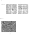
FIG. 1A is a front view of a vehicle according toEmbodiment 1; -
FIG. 1B is a function block diagram of the vehicle according toEmbodiment 1; -
FIG. 2 is a function block diagram of an image processing system according toEmbodiment 1; -
FIG. 3 is a function block diagram of an abnormal image detection device according toEmbodiment 1; -
FIG. 4 shows an example of a left original image and a right original image; -
FIG. 5 shows an example of a parallax image prepared by using the original image shown inFIG. 4 ; -
FIG. 6 is a flowchart of the reliability determination by an edge intensity determination section; -
FIG. 7 is a flowchart of the reliability determination by a parallax value determination section; -
FIG. 8 is a flowchart of the reliability determination by a parallax value difference determination section; -
FIG. 9 is an explanatory diagram for obtaining a parallax value difference; -
FIG. 10 shows an example of an image formed by edge-enhancing the left original image inFIG. 4 ; -
FIG. 11 shows an example of original images with no attached extraneous material; -
FIG. 12 shows an example of a parallax image prepared by using the original image shown inFIG. 11 ; -
FIG. 13 is a diagram showing a parallax distribution in the parallax image shown inFIG. 12 ; -
FIG. 14 is a diagram showing a parallax distribution in the parallax image shown inFIG. 5 ; and -
FIG. 15 is a function block diagram of an abnormal image detection device according toEmbodiment 2. - A vehicle having an abnormal image detection device according to
Embodiment 1 will be described with reference to the drawings. An autonomously-traveling golf cart will be described below as the vehicle by way of example. The vehicle, however, is not limited to the golf cart. "Front/rear" and "left/right" are defined with respect to the direction in which the vehicle travels. For the description of the present embodiment, an image in a state with an attached extraneous material is used as an image providing a substantially different scene when compared to an image without an extraneous material. This kind of image is not exclusively used; any other kind of image representing a substantially different scene may suffice. - A
vehicle 1 shown inFIG. 1A, FIG. 1B ,FIG. 2 and FIG. 3 is a golf cart that travels automatically or is manually operated to travel in a golf course. Thevehicle 1 can travel autonomously by being guided by electromagnetic waves emitted from a guide wire embedded under a lane. Thevehicle 1 incorporates animage processing system 5 having animage pickup part 51, a parallaximage preparation part 52 that prepares a parallax image on the basis of a plurality of original images obtained from theimage pickup part 51, adistance computation part 53 that computes a depth distance on the basis of the parallax image prepared by the parallaximage preparation part 52, an abnormalimage detection device 2 that detects whether or not a parallax image, which has been prepared on the basis of a plurality of original images obtained from theimage pickup part 51, and at least one of the plurality of original images are abnormal, and anoutput part 54 that outputs abnormality information if the abnormalimage detection device 2 detects an abnormality in the parallax image. Theimage processing system 5 may also have anobstacle detection device 55 that detects an obstacle on the lane on which thevehicle 1 travels. InEmbodiment 1, thevehicle 1 is a vehicle guided by a guide wire and capable of traveling autonomously. However, the present invention is not limited to this. Thevehicle 1 can also be manually operated by a driver to travel and can travel freely on a lane having no guide wire. - The
vehicle 1, as shown inFIG. 1B is also provided with an autonomous travel control part 6 that controls autonomous travel of thevehicle 1 along the guide wire, awarning output part 7 that issues a warning to the driver and surroundings when theobstacle detection device 55 detects an obstacle, a travel speed control part 9 that controls deceleration or stopping upon detection of an obstacle, and adrive motor 11 that driveswheels 12 and has its rotational speed controlled by the travel speed control part 9. In the present embodiment, thevehicle 1 is driven by the motor. However, the present invention is not limited to this. Thevehicle 1 may be driven by an engine. - The
image processing system 5 will be described with reference toFIG. 2 . Theimage pickup part 51 is provided at an upper central portion of the front windshield of thevehicle 1. Theimage pickup part 51 is a stereo camera having aleft image sensor 511 and aright image sensor 512. The stereo camera may alternatively be constituted of two or more image sensors. Theleft image sensor 511 and theright image sensor 512 are, for example, visible-light cameras. Theleft image sensor 511 and theright image sensor 512 are disposed in a positional relationship so as to obtain parallel stereographic images. In the present embodiment, unless otherwise specially noted, theleft image sensor 511 is assumed to be a reference camera, and an image taken by theleft image sensor 511 is referred to as a reference image. Theimage processing system 5 has a microprocessor and a memory, with which the functions of its constituent sections are realized. - The parallax
image preparation part 52 prepares a parallax image by using as a left original image an image taken by theleft image sensor 511 and by using as a right original image an image taken by theright image sensor 512.FIG. 4(a) shows an example of a left original image, andFIG. 4(b) shows an example of a right original image. A blackened area wd in a central portion of the left original image signifies that the image was taken in a state where an extraneous material is attached to the lens front surface of theleft image sensor 511. - The parallax
image preparation part 52 prepares a parallax image by using a left original image as a reference image. Parallax images may be prepared with respect to all frames, or parallax images may be prepared by extracting arbitrary ones of the frames. In the present embodiment, parallax images are formed by extracting frames at predetermined intervals.FIG. 5 shows a parallax image prepared by using the left original image and the right original image shown inFIG. 4 . The parallaximage preparation part 52 also prepares, by using a right original image as a reference image, a parallax image to be used for reliability determination in a parallax value difference determination section. Each parallax image can be prepared, for example, by stereo matching or the like. An area correlation method is used as stereo matching. In the area correlation method, the degree of matching of each image is calculated with respect to a window of a certain size about a remarked pixel, and stereo matching is performed so that the degree of matching is maximized. Further, the parallax of the remarked pixel in the state where the degree of matching is maximized. The parallax thereby computed represents the amount of dislocation of the pixel among the plurality of images. InEmbodiment 1, the parallax is the amount of dislocation of the pixel in the right original image (left original image) from the left original image (or right original image) used as a reference image. - The
distance computation part 53 computes a depth distance on the basis of a parallax image prepared by the parallaximage preparation part 52. Regardless of abnormal parallax image or normal parallax image, thedistance computation part 53 computes a depth distance on the basis of parallax image formed by removing pixels having low reliability. In other word, when the pixels having low reliability are included in the normal parallax image, thedistance computation part 53 computes a depth distance on the basis of normal parallax image formed by removing pixels having low reliability. When the pixels having low reliability are included in the abnormal parallax image, thedistance computation part 53 computes a depth distance on the basis of abnormal parallax image formed by removing pixels having low reliability. By avoiding the use of the pixels having low reliability, the depth distance can be obtained with high accuracy. The depth distance is provided to theobstacle detection device 55 and the travel speed control part 9 for example. - The
output part 54 outputs abnormality information when the abnormalimage detection device 2 detects an abnormality in a parallax image. This output is, for example, a display of information on the abnormality on a display means, a sound or speech output through a speaker, an output through a lighting means or information on the abnormality may be transmitted to an external device. - The abnormal
image detection device 2 shown inFIG. 3 has areliability determination part 24 that determines whether or not pixels of a parallax image have low reliability, acomputation part 25 that computes the total number of pixels having low reliability, determined by thereliability determination part 24, and anabnormality determination part 26 that, when the total number of low reliability pixels obtained by thecomputation part 25 exceeds a predetermined value, determines that the parallax image is abnormal. - The
reliability determination part 24 has an edgeintensity determination section 241, a parallaxvalue determination section 242 and a parallax valuedifference determination section 243, which will be described in detail below. - A method of edge intensity determination as performed by the edge intensity determination section will be described with reference to
FIG. 6 . The edgeintensity determination section 241 determines, with respect to each of the pixels of a left original image and a right original image corresponding to pixels in a first region w of a parallax image, whether the edge intensity of the pixel is equal to or lower than a threshold value. A description will be given below of a method in which the determination of pixels of a left original image and the determination of pixels of a right original image are made in parallel with each other. The parallax image shown inFIG. 5 is prepared by performing stereo matching on the left original image shown inFIG. 4(a) and the right original image shown inFIG. 4(b) . The edgeintensity determination section 241 obtains the edge intensity eL (u, v) of the pixels of the left original image corresponding to the pixels p (u, v) in the first region w of the parallax image. Similarly, the edgeintensity determination section 241 obtains the edge intensity eR (u, v) of the pixels of the right original image corresponding to the pixels p (u, v) in the first region w of the parallax image (S1). The edge intensity can be obtained by ordinary edge detection. - In the present embodiment, the edge intensity eL (u, v) of the pixels of the left original image and the edge intensity eR (u, v) of the pixels of the right original image corresponding to the pixels p (u, v) in the first region w are obtained. However, the present invention is not limited to this. A modification may be made to the present embodiment such that the edge intensity eL (u, v) of pixels of a left original image corresponding to pixels pL in a region wL of a parallax image is obtained and the edge intensity eR (u, v) of pixels of a right original image corresponding to pixels pR in a region wR (a region different from the region wL) of the parallax image is obtained.
- Subsequently, the edge
intensity determination section 241 checks whether or not the edge intensity eL is equal to or lower than a threshold value EL1. Similarly, the edgeintensity determination section 241 checks whether or not the edge intensity eR is equal to or lower than a threshold value ER1 (S2). The threshold value EL1 and the threshold value ER1 may be equal to or different from each other. - If the edge intensity eL is equal to or lower than the threshold value EL1, the edge
intensity determination section 241 determines that the pixel of the left original image is a pixel having low reliability. Similarly, if the edge intensity eR is equal to or lower than the threshold value ER1, the edgeintensity determination section 241 determines that the pixel of the right original image is a pixel having low reliability (S3-1). Thecomputation part 25 counts the total number TL1 of pixels determined as having low reliability in the left original image. Similarly, thecomputation part 25 counts the total number TR1 of pixels determined as having low reliability in the right original image (S4). - On the other hand, if the edge intensity eL is not equal to or lower than the threshold value EL1, the edge
intensity determination section 241 determines that the pixel of the left original image is not a pixel having low reliability but a pixel having high reliability. Similarly, if the edge intensity eR is not equal to or lower than the threshold value ER1, the edgeintensity determination section 241 determines that the pixel of the right original image is not a pixel having low reliability but a pixel having high reliability (S3-2). The pixel not determined as a pixel having low reliability is referred to as a pixel having high reliability. Steps S2 to S4 are repeated with respect to all the pixels of the left original image and the right original image in the pixels in the first region w (S5). - Subsequently, the
abnormality determination part 26 determines whether or not the total number TL1 of pixels having low reliability exceeds a predetermined value QL1. Similarly, theabnormality determination part 26 determines whether or not the total number TR1 exceeds a predetermined value QR1 (S6). The predetermined values QL1 and QR1 are set in advance. The predetermined values QL1 and QR1 may be equal to or different from each other. If the total number TL1 of pixels having low reliability exceeds the predetermined value QL1, theabnormality determination part 26 determines that the left original image is abnormal (not normal). Similarly, if the total number TR1 exceeds the predetermined value QR1, theabnormality determination part 26 determines that the right original image is abnormal (not normal) (S7). When theabnormality determination part 26 determines that at least one of the original images is abnormal, it determines that the parallax image is also abnormal. Theoutput part 54 can output information indicating this determination result, e.g., information indicating that an abnormal parallax image has been detected. Regardless of abnormal parallax image or normal parallax image, thedistance computation part 53 computes a depth distance on the basis of parallax image formed by removing pixels having low reliability. In the case where the total number TL1 of pixels having low reliability has not exceeded the predetermined value QL1 and where the total number TR1 has not exceeded the predetermined value QR1, determination by the parallaxvalue determination section 242 is executed. - A method of parallax value determination as performed by the parallax value determination section will be described with reference to
FIG. 7 . In the present embodiment, a first region, a second region and a third region in a parallax image relating to the parallax value determination are described as the same region w. However, the method is not limited to this. A modification may be made to the present embodiment such that the first region, the second region and the third region are different from each other. - If a parallax value d (u, v) of the pixel p (u, v) in the second region of a parallax image is out of a predetermined range, the parallax
value determination section 242 determines that the reliability of the pixel p (u, v) is low. The parallaxvalue determination section 242 first obtains the parallax value d (u, v) of the pixel p (u, v) (S11). The parallax value can be obtained by a conventional method. - The parallax
value determination section 242 checks whether or not the parallax value d (u, v) is equal to or higher than a lower limit value D1 and equal to or lower than an upper limit value D2 (S12). The lower limit value D1 and the upper limit value D2 are set in advance. If the parallax value d (u, v) is equal to or higher than the lower limit value D1 and equal to or lower than the upper limit value D2, the parallaxvalue determination section 242 determines that the pixel has low reliability (S13-1). If the pixel is determined as having low reliability, thecomputation part 25 counts the total number T2 of pixels having low reliability (S14). On the other hand, if the parallax value d (u, v) is not equal to or higher than the lower limit value D1 and not equal to or lower than the upper limit value D2, the parallaxvalue determination section 242 determines that the pixel of the right original image is not a pixel having low reliability but a pixel having high reliability (S13-2). Steps S12 to S14 are repeated with respect to all the pixels in the second region w (S15). - Subsequently, the
abnormality determination part 26 determines whether or not the total number T2 of pixels having low reliability exceeds a predetermined value Q2 (S16). The predetermined value Q2 is set in advance. If the total number T2 of pixels having low reliability exceeds the predetermined value Q2, theabnormality determination part 26 determines that the parallax image and at least one of the original images are abnormal (not normal) (S17). When the images are determined as abnormal, theoutput part 54 can output information indicating this determination result, e.g., information indicating that an abnormal parallax image has been detected. Regardless of abnormal parallax image or normal parallax image, thedistance computation part 53 computes a depth distance on the basis of the parallax image formed by removing pixels having low reliability. In the case where the total number T2 of pixels having low reliability has not exceeded the predetermined value Q2, determination by the parallax valuedifference determination section 243 is executed. - A method of parallax value determination as performed by the parallax value determination difference section will be described with reference to
FIG. 8 . For example, a third region w is set in a parallax image with respect to a left original image reference, and a parallax value dL (u, v) of a pixel pL (u, v) in this region w is dL (u, v) = d. In this case, if the difference (dL - dR) from a parallax value dR of a pixel pR (u - d, v) of the parallax image with respect to a right original image reference, corresponding to the pixel pL (u, v), is out of a predetermined range, the parallax valuedifference determination section 243 determines that the pixel pL (u, v) has low reliability. A modification may be made to the present embodiment such that a fourth region w is set in a parallax image with respect to a right original image reference and the reliability is determined with respect to a pixel pR (u, v). In such a case, the parallax value of the parallax image with respect to a left original image reference corresponding to the parallax value dR (u, v) = d of the parallax image with respect to the right original image reference is dL (u + d, v). If the difference (dL - dR) is out of a predetermined range, the parallax valuedifference determination section 243 determines that the pixel pR (u, v) has low reliability. The third region and the fourth region may be identical to or different from each other. The parallax image with respect to the left original image reference and the parallax image with respect to the right original image reference are prepared by the parallaximage preparation part 52. The parallax valuedifference determination section 243 first obtains the parallax value difference (dL - dR) (S21). - The parallax value
difference determination section 243 checks whether or not the parallax value difference (dL - dR) is equal to or higher than a lower limit value D3 and equal to or lower than an upper limit value D4 (S22). The lower limit value D3 and the upper limit value D4 are set in advance. If the parallax value difference (dL - dR) is equal to or higher than a lower limit value D3 and equal to or lower than an upper limit value D4, the parallax valuedifference determination section 243 determines that the pixel pL (u, v) has low reliability (S23-1). - An example of the process of obtaining a parallax value difference will be described with reference to
FIG. 9. FIG. 9(a) shows parallax values of a parallax image with respect to a left original image reference.FIG. 9(b) shows parallax values of a parallax image with respect to a right original image reference. ForFIGS. 9(a) and 9(b) , the same coordinates are extracted. Comparison is made between the parallax image with respect to the left original image reference and the parallax image with respect to the right original image reference. In a frame of the parallax image with respect to the left original image reference, the u-coordinate is 18 and the parallax value is 4. If the difference of the u-coordinate (the amount of displacement) is 4, the corresponding u-coordinate of the parallax image with respect to the right original image reference at the same v-coordinate is 14 (= 18-4), and the parallax value at the u-coordinate 14 is 9. The parallax value difference is "5 (= 9-4)". When D3 = 0 and D4 = 1, the parallax value difference is "5" exceeds D4. The pixel at this coordinate is therefore determined as having low reliability. - If the pixel is determined as having low reliability, the
computation part 25 counts the total number T3 of pixels having low reliability (S24). If the parallax value difference (dL - dR) is not equal to or higher than a lower limit value D3 and not equal to or lower than an upper limit value D4, the parallax valuedifference determination section 243 determines that the pixel pL (u, v) is not a pixel having low reliability but a pixel having high reliability (S23-2). Steps S22 to S24 are repeated with respect to all the pixels in the third region w (S25). - Subsequently, the
abnormality determination part 26 determines whether or not the total number T3 of pixels having low reliability exceeds a predetermined value Q3 (S26). The predetermined value Q3 is set in advance. If the total number T3 of pixels having low reliability exceeds the predetermined value Q3, theabnormality determination part 26 determines whether or not the parallax image and at least one of the original images are abnormal (not normal) (S27). When the images are determined as abnormal, theoutput part 54 can output information indicating this determination result, e.g., information indicating that an abnormal parallax image has been detected. Regardless of abnormal parallax image or normal parallax image, thedistance computation part 53 computes a depth distance on the basis of the parallax image formed by removing pixels having low reliability. In the case where the total number T3 of pixels having low reliability has not exceeded the predetermined value Q3, theabnormality determination part 26 determines that the parallax image and the original images are not abnormal. - In
Embodiment 1 described above, the edgeintensity determination section 241 determines whether or not the edge intensity is equal to or lower than a threshold value. The operation of this section is not limited to this. The edgeintensity determination section 241 may determine whether or not the edge intensity is within a predetermined range. - In
Embodiment 1 described above, the edge intensity may be, for example, a value (luminance value) after processing by an edge enhancement means such as a SOBEL filter.FIG. 10 shows an example of an image obtained by edge-enhancing the left original image shown inFIG. 4 . - In
Embodiment 1 described above, the parallaxvalue determination section 242 may determine that the corresponding pixel p (u, v) has low reliability, when the parallax value d (u, v) is equal to or lower than a threshold value. - In
Embodiment 1 described above, the parallaxvalue determination section 242 may determine that the pixel has low reliability when the parallax value difference (dL - dR) is equal to or lower than a threshold value. - In
Embodiment 1 described above, the edgeintensity determination section 241 performs processing of a left original image and processing of a right original image in parallel with each other (S1 to S7). The operation of this section is not limited to this. The edgeintensity determination section 241 may perform processing of one of the original images and thereafter execute processing of the other original image. - In
Embodiment 1 described above, processing by the edgeintensity determination section 241, processing by the parallaxvalue determination section 242 and processing by the parallax valuedifference determination section 243 are executed in this order. The processing order is not limited to this. The order of processing by the edgeintensity determination section 241, processing by the parallax valuedifference determination section 243 and processing by the parallaxvalue determination section 242 may alternatively be selected. - In
Embodiment 1 described above, an arrangement not having the abnormalimage detection device 2 provided on thevehicle 1 may alternatively be adopted. In such a case, theimage processing system 5 and the abnormalimage detection device 2 are connected to each other via a network. Also, an arrangement not having theimage processing system 5 provided on thevehicle 1 may alternatively be adopted. Images taken by theimage pickup part 51 provided on thevehicle 1 are transmitted to theimage processing system 5 via a network. - In
Embodiment 1 described above, the parallaximage preparation part 52 may prepare a parallax image from images obtained by making various corrections to images taken by theleft image sensor 511 and theright image sensor 512. In such a case, theimage processing system 5 has an image correction part (not shown) for performing various kinds of correction processing of the images. Images corrected by the image correction part are output to the parallaximage preparation part 52. Examples of image correction processing are a luminance correction processing for correcting a luminance variation between the plurality of image sensors, for example, due to the apertures and colors of lenses, a distortion correction processing for correcting distortions due to the lenses for the image sensors, and an edge enhancement processing for enhancing edges of taken images. At least one of these kinds of image processing may be executed for image correction. The evenness of characteristics of images obtained from intrinsic characteristics of the left andright image sensors right image sensors right image sensors -
Embodiment 1 described above may further have an index computation part that computes an index of a standard deviation (dispersion) of parallax values in a predetermined region (pixels) of a parallax image. If the index computed by the index computation part is out of a predetermined range (or the index exceeds an upper limit threshold value), the abnormality determination part determines that the parallax image is abnormal. With this arrangement, it is possible to determine, through determination of large variation in parallax value, that an original image is abnormal. The "predetermined region of a parallax image" is, for example, the whole pixel region or a central region defined by removing an end region from the whole pixel region. In the end region, the plurality of image pickup parts have different image pickup areas. It is, therefore, preferable to exclude the end region in advance. The "predetermined region of a parallax image" may be the same as one of the above-described "first region of a parallax image", "second region of the parallax image" and "third region of the parallax image" or may be different from these regions. - The above-described "first region of a parallax image", "second region of the parallax image" and "third region of the parallax image" are each a central region defined by removing an end region from the entire region. However, the first to third regions are not limited to this. Each of the first to third regions may be the entire region.
-
Embodiment 1 described above may further have a pixel value difference calculation part that calculates, with respect to pixels in a predetermined region of at least two of original images, the difference between pixel values (luminance values) of pixels of the original images at the same coordinates, and an index calculation part that calculates one or more data selected from the total, average, maximum, minimum and standard deviation of the differences between the pixel values obtained by the pixel value difference calculation part. If the index is out of a predetermined range (or the index exceeds an upper limit threshold value), the abnormality determination part determines that at least one of the two original images is abnormal. With this arrangement, it is possible to determine, through determination of a large difference in luminance value, that an original image is abnormal. The "predetermined region of original images" is, for example, the whole pixel region or central region defined by removing an end region from the whole pixel region. - The
vehicle 1 inEmbodiment 1 described above has a front windshield provided in front of the image pickup part in the image pickup direction. However, the present invention is not limited to this. For example, the image pickup part may be provided on a front portion of the vehicle. - In
Embodiment 1, regardless of abnormal parallax image or normal parallax image, thedistance computation part 53 computes a depth distance on the basis of the parallax image formed by removing pixels having low reliability. However, it is not limited to the above but may be the following. The distance computation part may compute a depth distance on the basis of a parallax image other than the parallax image in which an abnormality has been detected. When computing a depth distance by using a parallax image in which an abnormality has been detected, the distance computation part uses a parallax image formed by removing pixels having low reliability. - An abnormal
image detection device 2 according toEmbodiment 2 is arranged as a device separate from theimage processing system 5. The abnormalimage detection device 2 shown inFIG. 15 further has a communication part 21 (corresponding to the acquisition part) that receives a left original image, a right original image and a parallax image from an external device, and astorage part 22 that stores the left original image, the right original image and the parallax image received by thecommunication part 21. Thecommunication part 21 has a function to transmit information about an original image and a parallax image determined as abnormal to the external device or a different device. Thecommunication part 21 transmits, for example, information for identification of original images and parallax images to the external device or the different device. The external device may be theimage processing system 5 or a server of an information information processing device connected to the abnormalimage detection device 2 via a network. - The reliability determination in
Embodiment 1 described above and the reliability determination using the parallax distribution in the above-mentionedJP 2014-006243 A FIG. 11(a) shows a left original image with no attached extraneous material, andFIG. 11(b) shows a right original image with no attached extraneous material.FIG. 12 shows the parallax image from the left and right original images. The parallax image with an attached extraneous material is the image shown inFIG. 5 .FIG. 13 shows a parallax distribution in the parallax image shown inFIG. 12 .FIG. 14 shows a parallax distribution in the parallax image shown inFIG. 5 . The abscissa represents the parallax value in the parallax distribution, and the ordinate represents the frequency of the parallax value. - In the determination according to
Embodiment 1 described above, it was possible to determine that the left original image with an attached extraneous material was abnormal. In determination using the parallax distribution according toJP 2014-006243 A JP 2014-006243 A - An abnormal image detection device according to another embodiment is an abnormal image detection device that detects whether or not a parallax image, which have been prepared on the basis of a plurality of original images obtained from a plurality of image pickup parts, and at least one of the plurality of original images are abnormal, and that has an index computation part that computes an index of a standard deviation (dispersion) of parallax values in a predetermined region (pixels) of the parallax image, and an abnormality determination part that determines that the parallax image is abnormal if the index computed by the index computation part is out of a predetermined range (or if the index exceeds an upper limit threshold value). With this arrangement, it is possible to determine, through a determination of large variation in parallax value, that an original image is abnormal. The abnormal image detection device may further has the components of the abnormal
image detection device 2 according toEmbodiment - An abnormal image detection device according to still another embodiment is an abnormal image detection device that detects whether or not a parallax image, which have been prepared on the basis of a plurality of original images obtained from a plurality of image pickup parts, and at least one of the plurality of original images are abnormal, and that has a pixel value difference calculation part that calculates, with respect to pixels in a predetermined region of at least two of the original images, the difference between pixel values (luminance values) of pixels of the original images at the same coordinates, an index calculation part that calculates one or more indexes selected from the total, average, maximum, minimum and standard deviation of the differences between the pixel values obtained by the pixel value difference calculation part, and an abnormality determination part that determines that at least one of the two original images is abnormal if the index is out of a predetermined range (or the index exceeds an upper limit threshold value). With this arrangement, it is possible to determine, through a determination of a large difference in luminance value, that an original image is abnormal. The abnormal image detection device may further has the components of the abnormal
image detection device 2 according toEmbodiment - Each "threshold value" according to the present invention may be a fixed value determined in advance or a corrected value obtained by correcting a fixed value on the basis of an environmental condition or a travel condition.
- Also, if a predetermined value is represented by A; another predetermined value is represented by B; and A is smaller than B, "within a predetermined range" according to the present invention includes all the following conditions:
- being larger than A and smaller than B; being larger than A and smaller than or equal to B; being larger than or equal to A and smaller than or equal to B; and being larger than or equal to A and smaller than B.
- The vehicle according to the present invention is not limited to golf cars. The vehicle is not limited in the number of wheels. The vehicle may be a saddle-ride vehicle, which comprises types of motorcycle other than scooters. The saddle-ride vehicle may be any of vehicles other than motorcycles such as all terrain vehicles (ATVs). The saddle-ride vehicle means a vehicle straddled by a rider to ride.
-
- 1
- Vehicle
- 2
- Abnormal image detection device
- 21
- Communication part
- 22
- Storage part
- 24
- Reliability determination part
- 241
- Edge intensity determination section
- 242
- Parallax value determination section
- 243
- Parallax value difference determination section
- 25
- Computation part
- 26
- Abnormality determination part
- 5
- Image processing system
- 51
- Image pickup part
- 52
- Parallax image preparation part
- 53
- Distance computation part
- 54
- Output part
Claims (8)
- An abnormal image detection device (2) configured to detect that at least one of a plurality of original images obtained from a plurality of image pickup parts (51) and used to prepare a parallax image is abnormal, the abnormal image detection device (2) comprising:a reliability determination part (24) configured to determine whether or not a pixel of the parallax image has low reliability;a computation part (25) configured to compute the total number of pixels having low reliability; andan abnormality determination part (26) configured to determines that the parallax image is abnormal, when the total number of pixels having low reliability exceeds a predetermined value,wherein the reliability determination part (24) has an edge intensity determination section (241) configured to determine that the pixel in the parallax image prepared on the basis of the pixels of the original images is a pixel having low reliability, when the edge intensity of one of the pixels of the original images corresponding to the pixel in the parallax image is at least smaller than or equal to a threshold value.
- The abnormal image detection device (2) according to Claim 1, wherein the reliability determination part (24) has a parallax value determination section (242) configured to determine that the pixel has low reliability, when a parallax value of each one of the pixels of the parallax image is out of a predetermined range.
- The abnormal image detection device (2) according to Claim 1 or 2, wherein the parallax image includes at least a first parallax image (Ab) prepared with reference to a first original image (A) of the plurality of original images and a second parallax image (Ba) prepared with reference to a second original image (B) of the plurality of original images, and
wherein the reliability determination part (24) has a parallax value difference determination section (243) configured to determine that the first pixel (pA) has low reliability, when the difference (d1 - d2) between a first parallax value (d1) of a first pixel (pA) of the first parallax image (Ab) and a second parallax value (d2) of a second pixel (pB) of the second parallax image (Ba) corresponding to the first pixel (pA) is out of a predetermined range, determines that the first pixel (pA) has low reliability. - An image processing system (5) comprising:a plurality of image pickup parts (51);a parallax image preparation part 52) configured to prepare a parallax image on the basis of a plurality of original images obtained from the image pickup parts (51);a distance computation part (53) configured to compute a depth distance on the basis of the parallax image prepared by the parallax image preparation part (52);an abnormal image detection device (2) according to any one of Claims 1 to 3; andan output part (54) configured to output abnormality information when the abnormal image detection device (2) detects an abnormality in the original images.
- The image processing system (5) according to Claim 4, wherein the distance computation part (53) is configured to compute a depth distance on the basis of the parallax image other than the parallax image in which an abnormality has been detected.
- The image processing system (5) according to Claim 4, wherein in the parallax image prepared by the parallax image preparation part, the distance computation part (53) is configured to compute a depth distance on the basis of the parallax image formed by removing pixels having low reliability.
- A vehicle (1) comprising an image processing system (5) according to any one of Claim 4 to 6.
- The vehicle (1) according to Claim 7, comprising a front windshield in front of the image pickup parts (51) in the image pickup direction,
wherein no windshield wiper is provided on the front windshield.
Applications Claiming Priority (5)
| Application Number | Priority Date | Filing Date | Title |
|---|---|---|---|
| JP2015149524 | 2015-07-29 | ||
| JP2015157183A JP6690904B2 (en) | 2015-08-07 | 2015-08-07 | Self-driving vehicle |
| JP2015175792A JP6651313B2 (en) | 2015-09-07 | 2015-09-07 | Automatic traveling vehicle and automatic traveling system including the same |
| JP2016043199 | 2016-03-07 | ||
| JP2016127534A JP6657034B2 (en) | 2015-07-29 | 2016-06-28 | Abnormal image detection device, image processing system provided with abnormal image detection device, and vehicle equipped with image processing system |
Publications (1)
| Publication Number | Publication Date |
|---|---|
| EP3125197A1 true EP3125197A1 (en) | 2017-02-01 |
Family
ID=56990207
Family Applications (1)
| Application Number | Title | Priority Date | Filing Date |
|---|---|---|---|
| EP16181285.4A Withdrawn EP3125197A1 (en) | 2015-07-29 | 2016-07-26 | Abnormal image detection device, image processing system having an abnormal image detection device, and vehicle including an image processing system |
Country Status (5)
| Country | Link |
|---|---|
| US (1) | US10043262B2 (en) |
| EP (1) | EP3125197A1 (en) |
| KR (1) | KR101832189B1 (en) |
| CN (2) | CN106412551B (en) |
| TW (1) | TWI613905B (en) |
Cited By (4)
| Publication number | Priority date | Publication date | Assignee | Title |
|---|---|---|---|---|
| CN108762260A (en) * | 2018-05-16 | 2018-11-06 | 南京理工大学 | Crawler type independent navigation robot based on differential GPS and its air navigation aid |
| CN110021055A (en) * | 2018-01-09 | 2019-07-16 | 纬创资通股份有限公司 | The method and its image processing apparatus and system of generation disparity map |
| CN111667452A (en) * | 2019-03-07 | 2020-09-15 | 柯尼卡美能达株式会社 | Image inspection apparatus and image forming system |
| CN112116644A (en) * | 2020-08-28 | 2020-12-22 | 辽宁石油化工大学 | A vision-based obstacle detection method and device, and obstacle distance calculation method and device |
Families Citing this family (18)
| Publication number | Priority date | Publication date | Assignee | Title |
|---|---|---|---|---|
| KR101832189B1 (en) * | 2015-07-29 | 2018-02-26 | 야마하하쓰도키 가부시키가이샤 | Abnormal image detecting apparatus, image processing system with abnormal image detecting apparatus and vehicle mounted with image processing system |
| US11400860B2 (en) * | 2016-10-06 | 2022-08-02 | SMR Patents S.à.r.l. | CMS systems and processing methods for vehicles |
| JP6889059B2 (en) * | 2017-07-19 | 2021-06-18 | 株式会社東芝 | Information processing equipment, information processing methods and computer programs |
| JP6859907B2 (en) | 2017-09-08 | 2021-04-14 | トヨタ自動車株式会社 | Vehicle control unit |
| WO2019181591A1 (en) * | 2018-03-22 | 2019-09-26 | 日立オートモティブシステムズ株式会社 | In-vehicle stereo camera |
| US20190347786A1 (en) * | 2018-05-08 | 2019-11-14 | Pixart Imaging Inc. | Method, apparatus, and electronic device having living body detection capability |
| JP7064400B2 (en) * | 2018-07-19 | 2022-05-10 | 日立Astemo株式会社 | Object detection device |
| JP7234614B2 (en) * | 2018-12-10 | 2023-03-08 | トヨタ自動車株式会社 | Anomaly detection device, anomaly detection system and anomaly detection program |
| US11182623B2 (en) * | 2019-04-30 | 2021-11-23 | Baidu Usa Llc | Flexible hardware design for camera calibration and image pre-procesing in autonomous driving vehicles |
| JP7173062B2 (en) * | 2020-01-23 | 2022-11-16 | トヨタ自動車株式会社 | Change point detection device and map information distribution system |
| CN111476194B (en) * | 2020-04-20 | 2024-02-27 | 海信集团有限公司 | Detection method for working state of sensing module and refrigerator |
| EP3923241B1 (en) | 2020-06-09 | 2022-04-06 | Axis AB | Aligning digital images |
| TWI756723B (en) * | 2020-06-29 | 2022-03-01 | 大陸商北京集創北方科技股份有限公司 | A method for recognizing false touches on a foldable touch display device, a foldable touch display device, and an information processing device |
| CN111818330A (en) * | 2020-07-02 | 2020-10-23 | 浙江大华技术股份有限公司 | Image abnormality detection method and apparatus, storage medium, and electronic apparatus |
| CN116563563A (en) * | 2022-01-28 | 2023-08-08 | 北京小米移动软件有限公司 | Image abnormality detection method, device, terminal and storage medium |
| CN117218069A (en) * | 2023-08-30 | 2023-12-12 | 北京奇艺世纪科技有限公司 | Anomaly detection method, device, electronic equipment and medium |
| CN118379436B (en) * | 2024-06-21 | 2024-08-16 | 云士康(深圳)智能科技有限公司 | Method, device, equipment and storage medium for generating three-dimensional virtual scene |
| US20260042346A1 (en) * | 2024-08-07 | 2026-02-12 | Textron Inc. | Vehicle emergency event detection system |
Citations (3)
| Publication number | Priority date | Publication date | Assignee | Title |
|---|---|---|---|---|
| US20090180682A1 (en) * | 2008-01-11 | 2009-07-16 | Theodore Armand Camus | System and method for measuring image quality |
| US20090187308A1 (en) * | 2008-01-18 | 2009-07-23 | Noboru Morimitsu | Vehicle Surroundings Monitoring Apparatus |
| JP2014006243A (en) | 2012-05-28 | 2014-01-16 | Ricoh Co Ltd | Abnormality diagnostic device, abnormality diagnostic method, imaging apparatus, moving body control system and moving body |
Family Cites Families (56)
| Publication number | Priority date | Publication date | Assignee | Title |
|---|---|---|---|---|
| JP3355354B2 (en) | 1993-10-12 | 2002-12-09 | ヤマハ発動機株式会社 | Fixed point information discriminating device for track running vehicles |
| TW375583B (en) | 1996-02-28 | 1999-12-01 | Nat Science Council | Development of an intelligent automotive steering system cooperative copilot |
| JP2001028056A (en) * | 1999-07-14 | 2001-01-30 | Fuji Heavy Ind Ltd | Stereoscopic outside vehicle monitoring device having fail safe function |
| JP4925498B2 (en) * | 2000-07-12 | 2012-04-25 | 富士重工業株式会社 | Outside vehicle monitoring device with fail-safe function |
| JP4953498B2 (en) * | 2000-07-12 | 2012-06-13 | 富士重工業株式会社 | Outside vehicle monitoring device with fail-safe function |
| TWM335688U (en) | 2008-01-03 | 2008-07-01 | Univ Kao Yuan | Route positioning navigation system for unmanned ground vehicle |
| JP2009271608A (en) | 2008-04-30 | 2009-11-19 | Murata Mach Ltd | Travelling vehicle and travelling vehicle system |
| TWI407280B (en) * | 2009-08-20 | 2013-09-01 | Nat Univ Tsing Hua | Automatic searching system and method |
| KR101214474B1 (en) * | 2009-09-15 | 2012-12-24 | 한국전자통신연구원 | Navigation apparatus and driving route information offering method using by it, automatic driving system and its method |
| KR20120083471A (en) | 2009-11-19 | 2012-07-25 | 가부시끼가이샤 오까무라세이사꾸쇼 | Goods conveying device |
| JP5387856B2 (en) * | 2010-02-16 | 2014-01-15 | ソニー株式会社 | Image processing apparatus, image processing method, image processing program, and imaging apparatus |
| WO2012002020A1 (en) * | 2010-06-30 | 2012-01-05 | 富士フイルム株式会社 | Playback device, compound-eye imaging device, playback method and program |
| US8878950B2 (en) * | 2010-12-14 | 2014-11-04 | Pelican Imaging Corporation | Systems and methods for synthesizing high resolution images using super-resolution processes |
| SG182880A1 (en) * | 2011-02-01 | 2012-08-30 | Univ Singapore | A method and system for interaction with micro-objects |
| JP5693994B2 (en) * | 2011-02-16 | 2015-04-01 | 富士重工業株式会社 | Vehicle detection device |
| US8760499B2 (en) * | 2011-04-29 | 2014-06-24 | Austin Russell | Three-dimensional imager and projection device |
| TWI426241B (en) | 2011-05-16 | 2014-02-11 | Nat Univ Chung Hsing | Self - propelled device for the tracking system |
| CN103874960B (en) * | 2011-09-13 | 2017-02-15 | 富士胶片株式会社 | Monocular stereoscopic imaging device, imaging method, and program |
| JP5639283B2 (en) * | 2011-11-25 | 2014-12-10 | 本田技研工業株式会社 | Vehicle periphery monitoring device |
| TWI455073B (en) | 2011-12-14 | 2014-10-01 | Ind Tech Res Inst | Road-condition warning device, system and method for a vehicle |
| JP5948983B2 (en) * | 2012-03-09 | 2016-07-06 | オムロン株式会社 | Image processing apparatus, image processing method, and image processing program |
| CN104272715A (en) * | 2012-05-01 | 2015-01-07 | 中央工程株式会社 | Stereo camera and stereo camera system |
| US9667845B2 (en) * | 2012-07-13 | 2017-05-30 | Ram Srikanth Mirlay | Variable 3-dimensional adaptor assembly for camera |
| CN104641625B (en) * | 2012-09-19 | 2018-05-11 | 富士胶片株式会社 | Image processing apparatus, camera device and image processing method |
| CN103092202B (en) | 2012-12-31 | 2015-07-08 | 浙江国自机器人技术有限公司 | Robot track positioning method and robot track positioning system |
| EP2963615B1 (en) * | 2013-02-27 | 2019-04-10 | Hitachi Automotive Systems, Ltd. | Imaging device, and vehicle control device |
| JP5950166B2 (en) * | 2013-03-25 | 2016-07-13 | ソニー株式会社 | Information processing system, information processing method of image processing system, imaging apparatus, imaging method, and program |
| KR101319526B1 (en) | 2013-03-26 | 2013-10-21 | 고려대학교 산학협력단 | Method for providing location information of target using mobile robot |
| JP6121776B2 (en) * | 2013-03-29 | 2017-04-26 | ソニー株式会社 | Image processing apparatus and image processing method |
| TW201444543A (en) | 2013-05-21 | 2014-12-01 | Univ Nat Chiao Tung | Self-propelled cart |
| KR101463464B1 (en) | 2013-06-03 | 2014-11-21 | 국방과학연구소 | Driveable path detection apparatus, moving objection having th same and method of detectiing driveable path |
| JP6110256B2 (en) * | 2013-08-21 | 2017-04-05 | 株式会社日本自動車部品総合研究所 | Object estimation apparatus and object estimation method |
| TWI535589B (en) | 2013-09-24 | 2016-06-01 | Active automatic driving assistance system and method | |
| CN104574342B (en) * | 2013-10-14 | 2017-06-23 | 株式会社理光 | The noise recognizing method and Noise Identification device of parallax depth image |
| JP6248533B2 (en) * | 2013-10-22 | 2017-12-20 | 富士通株式会社 | Image processing apparatus, image processing method, and image processing program |
| TWI570424B (en) | 2013-11-27 | 2017-02-11 | 財團法人資訊工業策進會 | Positioning method and electronic apparatus thereof |
| JP6261361B2 (en) | 2014-02-04 | 2018-01-17 | キヤノン株式会社 | Solid-state imaging device and camera |
| JP6247122B2 (en) | 2014-03-17 | 2017-12-13 | セイコーインスツル株式会社 | Electronic devices |
| KR101565007B1 (en) * | 2014-05-30 | 2015-11-02 | 엘지전자 주식회사 | Driver assistance apparatus and Vehicle including the same |
| IL250028B (en) * | 2014-07-14 | 2022-08-01 | Nova Ltd | Method and optical system for detecting defects in three-dimensional structures |
| JP2016043199A (en) | 2014-08-26 | 2016-04-04 | ネット株式会社 | Game machine |
| EP3002550B1 (en) * | 2014-10-03 | 2017-08-30 | Ricoh Company, Ltd. | Information processing system and information processing method for distance measurement |
| US10810715B2 (en) * | 2014-10-10 | 2020-10-20 | Hand Held Products, Inc | System and method for picking validation |
| US20160137125A1 (en) * | 2014-11-17 | 2016-05-19 | Caterpillar Inc. | Imaging system using virtual projection geometry |
| US10152890B2 (en) * | 2015-01-20 | 2018-12-11 | Hitachi Automotive Systems, Ltd. | On-vehicle camera device |
| CN105866949B (en) * | 2015-01-21 | 2018-08-17 | 成都理想境界科技有限公司 | The binocular AR helmets and depth of field adjusting method of the depth of field can be automatically adjusted |
| JP2015157183A (en) | 2015-06-10 | 2015-09-03 | 株式会社三洋物産 | Game machine |
| KR101832189B1 (en) * | 2015-07-29 | 2018-02-26 | 야마하하쓰도키 가부시키가이샤 | Abnormal image detecting apparatus, image processing system with abnormal image detecting apparatus and vehicle mounted with image processing system |
| US9565363B1 (en) * | 2015-08-10 | 2017-02-07 | X Development Llc | Stabilization of captured images for teleoperated walking biped robots |
| US9989965B2 (en) * | 2015-08-20 | 2018-06-05 | Motionloft, Inc. | Object detection and analysis via unmanned aerial vehicle |
| DE112015006347T5 (en) * | 2015-09-30 | 2017-12-07 | Komatsu Ltd. | Imaging device |
| US10127459B2 (en) * | 2015-12-17 | 2018-11-13 | Ford Global Technologies, Llc | Trailer type identification system |
| US10011228B2 (en) * | 2015-12-17 | 2018-07-03 | Ford Global Technologies, Llc | Hitch angle detection for trailer backup assist system using multiple imaging devices |
| US10155478B2 (en) * | 2015-12-17 | 2018-12-18 | Ford Global Technologies, Llc | Centerline method for trailer hitch angle detection |
| US9827818B2 (en) * | 2015-12-17 | 2017-11-28 | Ford Global Technologies, Llc | Multi-stage solution for trailer hitch angle initialization |
| US9672446B1 (en) * | 2016-05-06 | 2017-06-06 | Uber Technologies, Inc. | Object detection for an autonomous vehicle |
-
2016
- 2016-07-14 KR KR1020160089281A patent/KR101832189B1/en active Active
- 2016-07-26 EP EP16181285.4A patent/EP3125197A1/en not_active Withdrawn
- 2016-07-27 US US15/221,591 patent/US10043262B2/en active Active
- 2016-07-27 TW TW105123796A patent/TWI613905B/en active
- 2016-07-28 CN CN201610615709.1A patent/CN106412551B/en active Active
- 2016-07-28 CN CN201910905232.4A patent/CN110458155B/en active Active
Patent Citations (3)
| Publication number | Priority date | Publication date | Assignee | Title |
|---|---|---|---|---|
| US20090180682A1 (en) * | 2008-01-11 | 2009-07-16 | Theodore Armand Camus | System and method for measuring image quality |
| US20090187308A1 (en) * | 2008-01-18 | 2009-07-23 | Noboru Morimitsu | Vehicle Surroundings Monitoring Apparatus |
| JP2014006243A (en) | 2012-05-28 | 2014-01-16 | Ricoh Co Ltd | Abnormality diagnostic device, abnormality diagnostic method, imaging apparatus, moving body control system and moving body |
Non-Patent Citations (1)
| Title |
|---|
| FRADI HAJER ET AL: "Improved depth map estimation in stereo vision", STEREOSCOPIC DISPLAYS AND APPLICATIONS XXII, SPIE, 1000 20TH ST. BELLINGHAM WA 98225-6705 USA, vol. 7863, no. 1, 10 February 2011 (2011-02-10), pages 1 - 7, XP060006228, DOI: 10.1117/12.872544 * |
Cited By (6)
| Publication number | Priority date | Publication date | Assignee | Title |
|---|---|---|---|---|
| CN110021055A (en) * | 2018-01-09 | 2019-07-16 | 纬创资通股份有限公司 | The method and its image processing apparatus and system of generation disparity map |
| CN110021055B (en) * | 2018-01-09 | 2022-11-29 | 纬创资通股份有限公司 | Method for generating disparity map and image processing device and system thereof |
| CN108762260A (en) * | 2018-05-16 | 2018-11-06 | 南京理工大学 | Crawler type independent navigation robot based on differential GPS and its air navigation aid |
| CN111667452A (en) * | 2019-03-07 | 2020-09-15 | 柯尼卡美能达株式会社 | Image inspection apparatus and image forming system |
| CN111667452B (en) * | 2019-03-07 | 2023-10-31 | 柯尼卡美能达株式会社 | Image inspection device and image forming system |
| CN112116644A (en) * | 2020-08-28 | 2020-12-22 | 辽宁石油化工大学 | A vision-based obstacle detection method and device, and obstacle distance calculation method and device |
Also Published As
| Publication number | Publication date |
|---|---|
| KR20170015154A (en) | 2017-02-08 |
| CN110458155A (en) | 2019-11-15 |
| CN106412551B (en) | 2019-10-25 |
| US10043262B2 (en) | 2018-08-07 |
| CN106412551A (en) | 2017-02-15 |
| CN110458155B (en) | 2023-04-07 |
| KR101832189B1 (en) | 2018-02-26 |
| TW201717616A (en) | 2017-05-16 |
| TWI613905B (en) | 2018-02-01 |
| US20170032517A1 (en) | 2017-02-02 |
Similar Documents
| Publication | Publication Date | Title |
|---|---|---|
| US10043262B2 (en) | Abnormal image detection device, image processing system having abnormal image detection device, and vehicle incorporating image processing system | |
| KR101839813B1 (en) | Abnormal image detecting apparatus, image processing system with abnormal image detecting apparatus and vehicle mounted with image processing system | |
| JP6657034B2 (en) | Abnormal image detection device, image processing system provided with abnormal image detection device, and vehicle equipped with image processing system | |
| US8244027B2 (en) | Vehicle environment recognition system | |
| US11834038B2 (en) | Methods and systems for providing depth maps with confidence estimates | |
| CN102442307B (en) | Lane line estimating apparatus | |
| KR101579098B1 (en) | Stereo camera, driver assistance apparatus and Vehicle including the same | |
| EP2919197B1 (en) | Object detection device and object detection method | |
| US6813370B1 (en) | Lane marker recognizing apparatus | |
| US9405980B2 (en) | Arrow signal recognition device | |
| US20090190827A1 (en) | Environment recognition system | |
| US10635910B2 (en) | Malfunction diagnosis apparatus | |
| US20090243823A1 (en) | Vehicle environment recognition apparatus and preceding-vehicle follow-up control system | |
| US7920721B2 (en) | Vehicle-use image processing system, vehicle-use image processing method, vehicle-use image processing program, vehicle, and method of formulating vehicle-use image processing system | |
| US20080118149A1 (en) | Method and apparatus for partitioning an object from an image | |
| KR20150068833A (en) | Stereo camera, driver assistance apparatus and Vehicle including the same | |
| US20200372794A1 (en) | Method of detecting speed using difference of distance between object and monitoring camera | |
| JP4930046B2 (en) | Road surface discrimination method and road surface discrimination device | |
| KR20170055738A (en) | Apparatus and method for recognize driving lane on image | |
| US20120128211A1 (en) | Distance calculation device for vehicle | |
| US9041778B2 (en) | Image processing device and method of processing image | |
| JP7122394B2 (en) | Imaging unit controller | |
| CN114820816B (en) | Automatic calibration method, device, equipment and medium for height of vehicle-mounted camera | |
| CN112334944B (en) | Mark recognition method and mark recognition device of camera device | |
| JP2008042759A (en) | Image processing device |
Legal Events
| Date | Code | Title | Description |
|---|---|---|---|
| PUAI | Public reference made under article 153(3) epc to a published international application that has entered the european phase |
Free format text: ORIGINAL CODE: 0009012 |
|
| AK | Designated contracting states |
Kind code of ref document: A1 Designated state(s): AL AT BE BG CH CY CZ DE DK EE ES FI FR GB GR HR HU IE IS IT LI LT LU LV MC MK MT NL NO PL PT RO RS SE SI SK SM TR |
|
| AX | Request for extension of the european patent |
Extension state: BA ME |
|
| 17P | Request for examination filed |
Effective date: 20170516 |
|
| RBV | Designated contracting states (corrected) |
Designated state(s): AL AT BE BG CH CY CZ DE DK EE ES FI FR GB GR HR HU IE IS IT LI LT LU LV MC MK MT NL NO PL PT RO RS SE SI SK SM TR |
|
| 17Q | First examination report despatched |
Effective date: 20180927 |
|
| GRAJ | Information related to disapproval of communication of intention to grant by the applicant or resumption of examination proceedings by the epo deleted |
Free format text: ORIGINAL CODE: EPIDOSDIGR1 |
|
| RIC1 | Information provided on ipc code assigned before grant |
Ipc: G08G 1/16 20060101ALI20190826BHEP Ipc: G06T 7/00 20170101AFI20190826BHEP Ipc: H04N 13/204 20180101ALI20190826BHEP |
|
| GRAP | Despatch of communication of intention to grant a patent |
Free format text: ORIGINAL CODE: EPIDOSNIGR1 |
|
| INTG | Intention to grant announced |
Effective date: 20191011 |
|
| RIN1 | Information on inventor provided before grant (corrected) |
Inventor name: AKASAKA, TAKASHI Inventor name: ISHII, TAKAHIRO |
|
| STAA | Information on the status of an ep patent application or granted ep patent |
Free format text: STATUS: THE APPLICATION IS DEEMED TO BE WITHDRAWN |
|
| 18D | Application deemed to be withdrawn |
Effective date: 20200222 |