EP3124930A1 - Soft magnetic component for torque sensor, and torque sensor using same - Google Patents
Soft magnetic component for torque sensor, and torque sensor using same Download PDFInfo
- Publication number
- EP3124930A1 EP3124930A1 EP15769348.2A EP15769348A EP3124930A1 EP 3124930 A1 EP3124930 A1 EP 3124930A1 EP 15769348 A EP15769348 A EP 15769348A EP 3124930 A1 EP3124930 A1 EP 3124930A1
- Authority
- EP
- European Patent Office
- Prior art keywords
- mass
- torque sensor
- soft magnetic
- magnetic
- range
- Prior art date
- Legal status (The legal status is an assumption and is not a legal conclusion. Google has not performed a legal analysis and makes no representation as to the accuracy of the status listed.)
- Granted
Links
Images



Classifications
-
- H—ELECTRICITY
- H01—ELECTRIC ELEMENTS
- H01F—MAGNETS; INDUCTANCES; TRANSFORMERS; SELECTION OF MATERIALS FOR THEIR MAGNETIC PROPERTIES
- H01F1/00—Magnets or magnetic bodies characterised by the magnetic materials therefor; Selection of materials for their magnetic properties
- H01F1/01—Magnets or magnetic bodies characterised by the magnetic materials therefor; Selection of materials for their magnetic properties of inorganic materials
- H01F1/03—Magnets or magnetic bodies characterised by the magnetic materials therefor; Selection of materials for their magnetic properties of inorganic materials characterised by their coercivity
- H01F1/12—Magnets or magnetic bodies characterised by the magnetic materials therefor; Selection of materials for their magnetic properties of inorganic materials characterised by their coercivity of soft-magnetic materials
- H01F1/14—Magnets or magnetic bodies characterised by the magnetic materials therefor; Selection of materials for their magnetic properties of inorganic materials characterised by their coercivity of soft-magnetic materials metals or alloys
- H01F1/147—Alloys characterised by their composition
- H01F1/14708—Fe-Ni based alloys
-
- B—PERFORMING OPERATIONS; TRANSPORTING
- B62—LAND VEHICLES FOR TRAVELLING OTHERWISE THAN ON RAILS
- B62D—MOTOR VEHICLES; TRAILERS
- B62D5/00—Power-assisted or power-driven steering
- B62D5/04—Power-assisted or power-driven steering electrical, e.g. using an electric servo-motor connected to, or forming part of, the steering gear
- B62D5/0457—Power-assisted or power-driven steering electrical, e.g. using an electric servo-motor connected to, or forming part of, the steering gear characterised by control features of the drive means as such
- B62D5/0481—Power-assisted or power-driven steering electrical, e.g. using an electric servo-motor connected to, or forming part of, the steering gear characterised by control features of the drive means as such monitoring the steering system, e.g. failures
-
- G—PHYSICS
- G01—MEASURING; TESTING
- G01L—MEASURING FORCE, STRESS, TORQUE, WORK, MECHANICAL POWER, MECHANICAL EFFICIENCY, OR FLUID PRESSURE
- G01L3/00—Measuring torque, work, mechanical power, or mechanical efficiency, in general
- G01L3/02—Rotary-transmission dynamometers
- G01L3/04—Rotary-transmission dynamometers wherein the torque-transmitting element comprises a torsionally-flexible shaft
- G01L3/10—Rotary-transmission dynamometers wherein the torque-transmitting element comprises a torsionally-flexible shaft involving electric or magnetic means for indicating
- G01L3/101—Rotary-transmission dynamometers wherein the torque-transmitting element comprises a torsionally-flexible shaft involving electric or magnetic means for indicating involving magnetic or electromagnetic means
- G01L3/102—Rotary-transmission dynamometers wherein the torque-transmitting element comprises a torsionally-flexible shaft involving electric or magnetic means for indicating involving magnetic or electromagnetic means involving magnetostrictive means
- G01L3/103—Details about the magnetic material used
Definitions
- the present invention relates to a soft magnetic component for a torque sensor used for detection of a torque and an angular velocity utilizing rotation of an axis, particularly, a soft magnetic component for a torque sensor used in a ring core and a yoke, and a torque sensor using the same, particularly, a torque sensor used in an electric power steering (hereinafter abbreviated to "EPS").
- EPS electric power steering
- the EPS is a system that properly assists a steering force by detecting the steering force from a steering wheel with a torque sensor, transmitting the detection signal as a torque signal to a control unit, and performing control of applying, to a motor, an electric current according to the torque signal.
- This torque sensor used in the EPS includes an input shaft coupled to the steering wheel, an output shaft coupled to a steering mechanism, a torsion bar coupling these two shafts, north poles and south poles of magnets provided around this torsion bar, a yoke, a ring core, and a detection portion including a Hall element or the like that detects magnetic flux, for example.
- the yoke and the ring core may be resin-molded.
- a magnetization curve (B-H curve) represented by a magnetic flux density (B) and the intensity of an external magnetic field (H) is a hysteresis curve.
- a magnetic body having a larger relative magnetic permeability described above is more likely to be magnetized by a weak magnetic field.
- a magnetic body more greatly magnetized by as a weak magnetic field as possible is preferably used.
- a magnetic body having a larger relative magnetic permeability is preferably used. Therefore, a coercive force (Hc) indicating the intensity of an external magnetic field necessary to reduce the magnetic flux density of the magnetic body to zero is preferably as small as possible.
- a material defined as SUS410L a Fe-based material having a small strain sensitivity disclosed in Patent Document 1
- a Fe-Ni based material having a large relative magnetic permeability and a small core loss disclosed in Patent Document 2 a Fe-Ni based material defined in JIS-C2531, or the like
- PC permalloy C
- the present inventors have found that the aforementioned problem can be solved by focusing on that a compression stress generated inside a soft magnetic material by resin shrinkage after resin molding causes degradation of the magnetic properties of the soft magnetic material and applying a soft magnetic material having a shrinkage property when a magnetic field is applied, and has arrived at the present invention.
- the present invention is a soft magnetic component for a torque sensor formed by resin-molding a soft magnetic material that contains Ni, Fe in such an amount that Fe/(Fe + Ni) is within a range from 10.0% to 16.0% in terms of mass ratio, and 3.5% by mass to 7.5% by mass of M (the above M represents one or more elements selected from among Mo, Nb, Cr, Cu, Ti, and W) and has a saturation magnetostriction of at least -4.0 ppm and less than 0 ppm.
- the above M may be Mo in an amount selected from a range of 3.5% by mass to 6.5% by mass.
- the above M may be Nb in an amount selected from a range of 5.0% by mass to 6.5% by mass.
- the above M may be Cr in an amount selected from a range of 3.5% by mass to 6.0% by mass.
- the above M may be a combination of Mo in an amount selected from a range of 3.5% by mass to 5.0% by mass and Cu in an amount selected from a range of 1.5% by mass to 2.5% by mass.
- the above M may be a combination of Mo in an amount selected from a range of 1.5% by mass to 6.0% by mass and Ti in an amount selected from a range of 0.5% by mass to 3.0% by mass.
- the above M may be a combination of Mo in an amount selected from a range of 1.0% by mass to 4.5% by mass and Nb in an amount selected from a range of 2.5% by mass to 5.0% by mass.
- the above M may be a combination of Mo in an amount selected from a range of 1.5% by mass to 4.5% by mass, Ti in an amount selected from a range of 1.0% by mass to 3.0% by mass, and W in an amount selected from a range of 0.2% by mass to 1.0% by mass.
- the above M may be a combination of Nb in an amount selected from a range of 2.5% by mass to 3.5% by mass, W in an amount selected from a range of 1.5% by mass to 2.5% by mass, and Ti in an amount selected from a range of 0.5% by mass to 1.5% by mass.
- the soft magnetic material preferably has a coercive force of 0 to 2.0 (A/m).
- the soft magnetic material preferably has a maximum relative magnetic permeability of at least 100,000.
- the soft magnetic component for a torque sensor according to the present invention is preferably used in a ring core for a torque sensor.
- the soft magnetic component for a torque sensor according to the present invention is preferably used in a yoke for a torque sensor.
- a torque sensor can be constructed of the aforementioned soft magnetic component for a torque sensor according to the present invention.
- the aforementioned torque sensor is preferably used in an electric power steering (EPS).
- EPS electric power steering
- the soft magnetic component for a torque sensor having the magnetic properties effective for a torque sensor can be obtained. Furthermore, the torque sensor, the high detection accuracy of which can be expected, can be obtained by using the soft magnetic component for a torque sensor.
- An important feature of the present invention is to apply, to resin molding, a soft magnetic material having a saturation magnetostriction of "at least -4.0 ppm and less than 0 ppm", which is less than zero, of soft magnetic materials having a shrinkage property when a magnetic field is applied.
- an addition element M
- Ni, and Fe addition elements
- predetermined various magnetic properties such as a coercive force, a maximum relative magnetic permeability, and an initial magnetic permeability, desired for a soft magnetic component for a torque sensor and a predetermined mechanical property.
- magnetic annealing is required, but a magnetic annealing condition lacking practicality is required according to the type of addition element and a balance of a chemical component.
- the saturation magnetostriction of a soft magnetic material to be resin-molded is a negative value.
- a magnetostriction ( ⁇ ) is a property in which the length of the magnetic body changes when a magnetic field is applied to a magnetic body (the soft magnetic material in the present invention), and the degree is represented by a saturation magnetostriction ( ⁇ s) in the present invention.
- the magnetic body forms a micro magnet having N-S poles in an atomic size, and has a small strain, and hence upon application of the magnetic field, the directions of the N-S poles of the micro magnet in an atomic size are aligned, and a strain ( ⁇ ) is aligned in the same direction over a crystal so that the shape is changed (strained).
- a mechanical strain ( ⁇ ) is often represented by a percentage (%), but the magnetostriction ( ⁇ ), which is a strain generated when the magnetic field is applied, is generally represented by parts per million [ppm], and hence this is followed.
- the soft magnetic material in the present invention has a magnetostriction in a compression direction (negative direction), and hence even when the shrinkage is applied in a state where a compression stress is internally generated by resin shrinkage caused by resin molding, self-shrinkage can be performed by a self-property of shrinkage (magnetostriction in the negative direction).
- a self-property of shrinkage magnetictostriction in the negative direction.
- the saturation magnetostriction of the soft magnetic material in the present invention is a negative value as described above, and is limited to "at least -4.0 ppm and less than 0 ppm". This is because it is necessary to have the predetermined magnetic properties applicable to the soft magnetic component for a torque sensor in the present invention, and it is not necessary to have a property of shrinking by an amount far exceeding an amount corresponding to a molding pressure due to resin molding and a compression stress generated due to resin shrinkage. For the magnetic properties, it is particularly important to have a small coercive force and a large maximum relative magnetic permeability, and the initial relative magnetic permeability is preferably large.
- the saturation magnetostriction that the soft magnetic material has is at least "0 (zero) ppm", i.e., it is zero or a positive value, the internal compression stress of the soft magnetic material resulting from the resin shrinkage at the time of resin molding is not reduced because of the soft magnetic material having no shrinkage property in the first place and being not self-shrunk.
- the preferable saturation magnetostriction is "a least -3.0 ppm and less than 0 ppm”
- the more preferable saturation magnetostriction is "a least -2.5 ppm and less than 0 ppm”.
- a resin to be used is a thermoplastic resin (plastic) material, PBT (polybutyleneterephthalate) or PPS (polyphenylenesulfide) is used, and glass fibers may be contained.
- a molding pressure is determined in consideration of the type of resin, the shape and size of a compact, etc., and the molding pressures of PBT and PPS can be considered to be in the range of 30 MPa to 180 MPa.
- a resin such as ABS (acrylonitrile-styrene copolymer), PS (polystyrene), AS (acrylonitrile-styrene), EVA (ethylene vinyl acetate), PP (polypropylene), HDPE (high density polyethylene), PMMA (methacrylic acid methyl ester), PA (polyamide), POM (polyacetal), PC (polycarbonate), or LCP (liquid crystal polymer) is conceivably usable.
- ABS acrylonitrile-styrene copolymer
- PS polystyrene
- AS acrylonitrile-styrene
- EVA ethylene vinyl acetate
- PP polypropylene
- HDPE high density polyethylene
- PMMA methacrylic acid methyl ester
- PA polyamide
- POM polyacetal
- PC polycarbonate
- LCP liquid crystal polymer
- the mold shrinkage percentages (a value obtained by representing a strain in a shrinkage direction by a percentage) of these resins are roughly within a range from 0.1% to 6.0%, and the mold shrinkage percentages of the aforementioned PBT and PPS can be considered to be within a range from 0.2% to 0.8%.
- the soft magnetic material suitable for resin molding obtained by making the type of addition element and a balance of a chemical component appropriate contains Ni (nickel), Fe (iron) in such an amount that Fe/(Fe + Ni) is within a range from 10.0% to 16.0% in terms of mass ratio, and 3.5% by mass to 7.5% by mass of M (the above M represents one or more elements selected from among Mo (molybdenum), Nb (niobium), Cr (chromium), Cu (copper), Ti (titanium), and W (tungsten)).
- the content of an element is hereinafter represented by mass % unless otherwise noted.
- Ni and Fe are necessary elements for obtaining the predetermined magnetic properties and the predetermined mechanical property applicable to the soft magnetic component for a torque sensor according to the present invention, and are elements that generate a basis material for the soft magnetic material.
- the basic magnetic properties of the soft magnetic material such as a coercive force, a maximum relative magnetic permeability, an initial relative magnetic permeability, an effective relative magnetic permeability, and a maximum magnetic flux density as well as a magnetostriction, are roughly determined by a content ratio of Ni and Fe.
- Fe is controlled such that Fe/(Fe + Ni) is within the range from 10.0% to 16.0% in terms of mass ratio, whereby the various magnetic properties (particularly a coercive force and a maximum relative magnetic permeability) of the soft magnetic material are stabilized.
- Fe is selectively contained from a range from roughly 8.3% by mass to 16.2% by mass such that Ni is within a range from 75.0% by mass to 85.0% by mass with respect to the entire mass of the soft magnetic material and Fe/(Fe + Ni) is within the range from 10.0% to 16.0% according to the above formula, whereby the basic magnetic properties of the soft magnetic material desired for a torque sensor can be obtained.
- the magnetic properties and the mechanical property desired for a torque sensor can be adjusted in the range of a practical magnetic annealing condition by containing the above M.
- at least one element represented by the above M influences stabilization of the magnetic annealing condition and the magnetic properties necessary for the soft magnetic material.
- the soft magnetic material that has obtained the practical magnetic annealing by containing the above M can have the aforementioned basic magnetic properties and a saturation magnetostriction of "at least -4.0 ppm and less than 0 ppm", which is smaller than zero, and hence a soft magnetic material suitable for the soft magnetic component for a torque sensor is obtained.
- the saturation magnetostriction may not be a negative value, or the cooling rate of the magnetic annealing to obtain the suitable magnetic properties may be increased so that this makes it difficult to achieve the practical use.
- the above M exceeds 7.5%, the content ratio of Ni and Fe is relatively reduced, and hence the basic magnetic properties necessary for a torque sensor may not be obtained.
- the maximum magnetic flux density may be reduced.
- the above M is preferably 3.8% by mass to 6.5% by mass, and the magnetic properties such as the maximum magnetic flux density as well as the coercive force and the maximum relative magnetic permeability can be made suitable.
- An element or a combination of elements to be contained in the above M other than the aforementioned elements is conceivable, but the above M is preferable since element adjustment, handling, etc. of the above M are easy in practice.
- Mo When only Mo is selected as the above M, for example, it may be 3.5% by mass to 6.5% by mass. Mo has an effect of making the aforementioned basic magnetic properties of the soft magnetic material obtained by Ni and Fe more desirable for a torque sensor, and an effect of widening the effective range of the predetermined cooling rate of the magnetic annealing necessary for that. When Mo exceeds 6.5%, an influence on the magnetic properties is increased, and hence it is necessary to pay attention to handling by more strictly controlling variations of the content, etc. When Mo is less than 3.5%, the saturation magnetostriction may be a positive value, an effect of improving another magnetic property is reduced, and an effect on the cooling rate becomes insufficient.
- Nb When only Nb is selected as the above M, for example, it may be 5.0% by mass to 6.5% by mass. Nb has an effect of improving the mechanical strength of the soft magnetic material in addition to an effect of making the aforementioned basic magnetic properties of the soft magnetic material obtained by Ni and Fe more desirable for a torque sensor. When Nb exceeds 6.5%, an influence on the magnetic properties is increased, and hence it is necessary to pay attention to handling by more strictly controlling variations of the content, etc. When Nb is less than 5.0%, effects of improving the magnetic properties and the mechanical strength tend to be reduced.
- Cr When only Cr is selected as the above M, for example, it may be 3.5% by mass to 6.0% by mass. Cr can improve the corrosion resistance of the soft magnetic material, but tends to slow the rise of the magnetic flux density so that Cr may have a bad influence on the magnetic properties such as a magnetic permeability. When Cr exceeds 6.0%, an influence on the magnetic properties is increased, and hence it is necessary to pay attention to handling by more strictly controlling variations of the content, etc. When Cr is less than 3.5%, not only an effect of improving the corrosion resistance becomes insufficient, but also the saturation magnetostriction may be a positive value.
- Mo and Cu When two of Mo and Cu are selected as the above M, for example, 3.5% by mass to 5.0% by mass of Mo and 1.5% by mass to 2.5% by mass of Cu may be combined within a range from 3.5% by mass to 7.5% by mass of the above M.
- Cu has a diamagnetic property to be magnetized in the opposite direction of a magnetic field by application of the magnetic field, and hence with respect to 3.5% to 5.0% of Mo, at least 1.5% of Cu is contained so that an effect of reducing the coercive force of the soft magnetic material can be promised.
- (Mo + Cu) exceeds 7.5%, however, the magnetic properties for a torque sensor become insufficient.
- Mo and Ti are selected as the above M, for example, 1.5% by mass to 6.0% by mass of Mo and 0.5% by mass to 3.0% by mass of Ti may be combined within the range from 3.5% by mass to 7.5% by mass of the above M.
- a combination of Mo and Ti has an effect of making the aforementioned basic magnetic properties of the soft magnetic material obtained by Ni and Fe more desirable for a torque sensor.
- Mo has an effect of widening the effective range of the predetermined cooling rate of the magnetic annealing, as described above.
- Ti has an effect of improving the mechanical strength of the soft magnetic material, etc.
- (Mo + Ti) exceeds 7.5% or is less than 3.5%, however, the magnetic properties suitable for a torque sensor may not be obtained.
- Mo and Nb When two of Mo and Nb are selected as the above M, for example, 1.0% by mass to 4.5% by mass of Mo and 2.5% by mass to 5.0% by mass of Nb may be combined within the range from 3.5% by mass to 7.5% by mass of the above M.
- a combination of Mo and Nb has an effect of making the aforementioned basic magnetic properties of the soft magnetic material obtained by Ni and Fe more desirable for a torque sensor.
- Mo has an effect of widening the effective range of the predetermined cooling rate of the magnetic annealing, as described above.
- Nb has an effect of improving the mechanical strength of the soft magnetic material, as described above.
- Mo, Ti, and W are selected as the above M, for example, 1.5% by mass to 4.5% by mass of Mo, 1.0% by mass to 3.0% by mass of Ti, and 0.2% by mass to 1.0% by mass of W may be combined within the range from 3.5% by mass to 7.5% by mass of the above M.
- a combination of Mo, Ti, and W has an effect of improving the mechanical strength of the soft magnetic material in addition to an effect of making the aforementioned basic magnetic properties of the soft magnetic material obtained by Ni and Fe more desirable for a torque sensor.
- Nb, W, and Ti are selected as the above M, for example, 2.5% by mass to 3.5% by mass of Nb, 1.5% by mass to 2.5% by mass of W, and 0.5% by mass to 1.5% by mass of Ti may be combined within the range from 3.5% by mass to 7.5% by mass of the above M.
- a combination of Nb, W, and Ti has an effect of improving the mechanical strength of the soft magnetic material in addition to an effect of making the aforementioned basic magnetic properties of the soft magnetic material obtained by Ni and Fe more desirable for a torque sensor.
- (Nb + W + Ti) exceeds 7.5%, however, the magnetic properties suitable for a torque sensor may not be obtained, and when (Nb + W + Ti) is less than 3.5%, the saturation magnetostriction may be a positive value.
- the soft magnetic material in the present invention may contain an element such as Si (silicon), Mn (manganese), Mg (magnesium), B (boron), Al (aluminum), C (carbon), S (sulfur), P (phosphorus), O (oxygen), or N (nitrogen) in addition to Ni, Fe, and the above M.
- an element such as Si (silicon), Mn (manganese), Mg (magnesium), B (boron), Al (aluminum), C (carbon), S (sulfur), P (phosphorus), O (oxygen), or N (nitrogen) in addition to Ni, Fe, and the above M.
- Si, Mn, and Al can be used as a deoxidizing agent, and Mn can be used as a desulfurizing agent.
- Si, Mn, and Mg contribute to improvement of hot workability
- B contributes to improvement of hot and warm forgibility and rollability.
- Si tends to slow the rise of the magnetic flux density and may have an unfavorable influence on the magnetic properties of the soft magnetic material, and hence Si is preferably not more than 2.0 mass %, more preferably not more than 1.0 mass %, still more preferably not more than 0.7 mass %, and may not be contained at all.
- Mn may not be contained at all, but Mn tends to hasten the rise of the magnetic flux density inversely to Si and may have a favorable influence on the magnetic properties of the soft magnetic material. Thus, at least 0.2 mass % of Mn may be contained. Although Mn produces the aforementioned function effect, too much Mn may have an unfavorable influence on the magnetic properties, and hence Mn is preferably reduced to not more than 0.7 mass %. Furthermore, too much Al and Mg may have an unfavorable influence on the magnetic properties, and hence Al and Mg are preferably not more than 0.05 mass %, more preferably not more than 0.02 mass %, and may not be contained at all.
- B is preferably not more than 0.01 mass %, more preferably not more than 0.005 mass %, and may not be contained at all.
- the other C, S, P, O, and N are reduced to as little as possible, and are preferably reduced to not more than 0.01 mass %, for example.
- Acoercive force influences the sensitivity, responsiveness, and hysteresis of a torque sensor.
- an output (voltage value) to an input (torque value), i.e. the sensitivity (V/kgf ⁇ m) is desired to be larger, and the hysteresis is desired to be smaller (an area in a hysteresis curve is desired to be smaller).
- the coercive force of the soft magnetic material before resin molding in the present invention is preferably not more than 2.0 (A/m), more preferably not more than 1.6 (A/m), still more preferably not more than 1.3 (A/m), and ideally zero. In this order, the hysteresis can be reduced.
- a maximum relative magnetic permeability influences the responsiveness and resolution of a torque sensor.
- a high resolution is desired in order to reduce a targeted control amount (torque value).
- the maximum relative magnetic permeability of the soft magnetic material before resin molding is preferably at least 100,000 in the present invention.
- the following magnetic properties are preferably in the range of a predetermined value.
- an initial relative magnetic permeability influences the responsiveness and resolution of a torque sensor, similarly to the maximum relative magnetic permeability.
- a value of the initial relative magnetic permeability is preferably as high as possible.
- the initial relative magnetic permeability ( ⁇ 0.4) of the soft magnetic material before resin molding is preferably at least 30,000, which is effective for improving the responsiveness and resolution of a torque sensor.
- the initial relative magnetic permeability ( ⁇ 0.4) denotes a relative magnetic permeability in a magnetic field 0.4 (A/m) based on the JIS standards (JIS-C2531).
- An effective relative magnetic permeability influences the sensitivity, responsiveness, and hysteresis of a torque sensor, similarly to the coercive force.
- a value of the effective relative magnetic permeability is preferably as high as possible.
- the effective relative magnetic permeability is influenced by an applied frequency and a sheet thickness obtained when the soft magnetic material is formed into the soft magnetic component in addition to the magnetic properties.
- a preferred value for the effective relative magnetic permeability is changed according to various conditions when used for a torque sensor, and hence it is difficult to univocally define the preferred value.
- an effective relative magnetic permeability tends to be increased.
- an applied frequency is increased, an influence of the thickness of the soft magnetic component is increased, and hence the reduced thickness of the soft magnetic component is more advantageous when a high frequency is applied.
- a maximum magnetic flux density is associated with reductions in the size and weight of the soft magnetic component for a torque sensor, and influences the shape sizes (particularly the volumes) of a ring core and a yoke, for example.
- the amount of magnetic flux capable of penetrating per volume is large, and hence magnetic flux generated in a magnetic circuit of a torque sensor is allowed to penetrate with a small volume, and the volume of the soft magnetic component for a torque sensor can be reduced.
- the maximum magnetic flux density of the soft magnetic material before resin molding is preferably at least 0.6 (T), which can contribute to reductions in the size and weight of the soft magnetic component for a torque sensor and can also contribute to reductions in the size and weight of a torque sensor using the same
- FIG. 1 schematically shows main portions of a typical torque sensor.
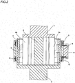
- Fig. 2 schematically shows a section of the main portions of the torque sensor shown in Fig. 1 , taken along an axial direction.
- This torque sensor includes an input shaft 1 coupled to a steering wheel (not shown), an output shaft 3 coupled to a steering mechanism (not shown), a torsion bar 2 coupling these two shafts, north poles 4a and south poles 4b of magnets provided around this torsion bar 2, a resin structure 5 provided around these magnets, and a resin structure 6 provided around the resin structure 5.
- the resin structure 5 is a resin-molded soft magnetic component including an upper yoke 7 and a lower yoke 8 (sometimes hereinafter collectively referred to as the "upper and lower yokes 7 and 8").
- the upper and lower yokes 7 and 8 have substantially the same shape, as shown in Fig. 3 , and multiple protrusions 7a and 8a fit together to alternately face each other.
- the resin structure 6 is a resin-molded soft magnetic component including an upper ring core 9, a lower ring core 10 (sometimes hereinafter collectively referred to as the "upper and lower ring cores 9 and 10"), and a detection portion 11 including a Hall element or the like that detects magnetic flux.
- the upper and lower ring cores 9 and 10 are also called a magnetic collecting ring, and have substantially the same shape, as shown in Fig. 4 .
- the detection portion 11 is provided in one location on the outer circumferences of the upper and lower ring cores 9 and 10 to protrude, and is arranged between a protrusion 9a of the upper ring core 9 and a protrusion 10a of a lower ring core 10.
- the upper and lower yokes 7 and 8 and the upper and lower ring cores 9 and 10 are arranged in a magnetic field generated by the north poles 4a and the south poles 4b of the magnets provided around the torsion bar 2, and a type of magnetic circuit id formed.
- the input shaft 1 is rotated by the rotation of the steering wheel, and the torsion bar 2 is rotated (or twisted) by the rotation of the input shaft 1.
- the amount of change in the magnetic flux lines (magnetic flux) induced by the aforementioned variation in the positional relationship of the upper and lower yokes 7 and 8 with respect to the magnets correlates with the amount of rotation (or the torsional angle) of the torsion bar 2, and hence the amount of rotation (or the torsional angle) of the torsion bar 2 can be measured by detecting this amount of change in the magnetic flux. More specifically, the amount of rotation (or the torsional angle) of the steering wheel connected to the torsion bar 2 through the input shaft 1 can be measured.
- this torque sensor it is important to have a predetermined resolution and have high responsiveness to an input, high reproducibility, and high sensitivity.
- quickness of the rise (magnetizing) and the fall (demagnetizing) of the changes in the magnetic flux lines, a low hysteresis property, and a large number of the magnetic flux lines allowed to penetrate become important. Therefore, as the magnetic properties desired for the upper and lower yokes 7 and 8 and the upper and lower ring cores 9 and 10, which are soft magnetic components, a large initial relative magnetic permeability, a large maximum relative magnetic permeability, a small coercive force, and a large maximum magnetic flux density become important. Particularly, the coercive force having a significant influence on the low hysteresis property should be considered to be important.
- the soft magnetic material in the present invention has a saturation magnetostriction of at least -4.0 ppm and less than 0 ppm so that changes in the magnetic properties before and after resin molding can be suppressed. Thus, it is effective to use it for the soft magnetic component for a torque sensor.
- the yokes and ring cores according to an embodiment of the soft magnetic component for a torque sensor in the present invention applicable to the aforementioned torque sensor for the EPS were manufactured by the following method.
- test specimen corresponding to each of Examples 1 to 19 and Comparative Examples 1 to 4 was prepared.
- the respective test specimens are described below as “Example 1" to “Example 19” and “Comparative Example 1” to “Comparative Example 4" for convenience.
- test specimens corresponding to Examples 1 to 19 are described as a "test specimen A”
- test specimens corresponding to Comparative Examples 1 to 4 are described as a "test specimen B”.
- Resin-molded test specimens A and B including the test specimens A and B prepared as described above were prepared by resin molding. Specifically, they were prepared by coating and molding (resin-molding) one test specimen in a predetermined shape using a composition for molding containing a main agent (PE-10 manufactured by AICA Kogyo Co., Ltd.) and a hardener (XNH2503 manufactured by Nagase ChemteX Corporation), defoaming the same under a vacuum atmosphere (by vacuuming), and performing heat hardening treatment on the same (holding the same at an atmospheric temperature of 85°C for 2 hours).
- a main agent PE-10 manufactured by AICA Kogyo Co., Ltd.
- a hardener XNH2503 manufactured by Nagase ChemteX Corporation
- the various magnetic properties of the prepared test specimens and the resin-molded test specimens as objects to be measured were measured. Specifically, the saturation magnetostriction ( ⁇ s), the initial relative magnetic permeability ( ⁇ 0.4), the maximum relative magnetic permeability ( ⁇ m), the maximum magnetic flux density (B800), the residual flux density (Br), the coercive force (Hc), and the effective relative magnetic permeability ( ⁇ e) were measured.
- the saturation magnetostriction was measured by a strain gauge method.
- the initial relative magnetic permeability ( ⁇ 0.4), the maximum relative magnetic permeability ( ⁇ m), the maximum magnetic flux density (B800), the residual flux density (Br), and the coercive force (Hc) were measured with a B-H tracer.
- Measurement results for the test specimens before resin molding are shown in Table 3, and measurement results for the resin-molded test specimens are shown in Table 4.
- Change rates of the coercive forces (Hc) before and after resin molding extracted from Table 3 and Table 4 are shown in Table 5, and change rates of the maximum relative magnetic permeability ( ⁇ m) before and after resin molding extracted from Table 3 and Table 4 are shown in Table 6.
- a graph for comparing changes in the coercive forces (Hc) before and after resin molding with respect to the saturation magnetostrictions is shown in Fig. 5
- a graph for comparing changes in the maximum relative magnetic permeabilities ( ⁇ m) before and after resin molding with respect to the saturation magnetostrictions is shown in Fig. 6 .
- Comparative Example 1 having a saturation magnetostriction of "+0.34 ppm" has an initial relative magnetic permeability of 180,000 and a maximum relative magnetic permeability of 329,000, which are high and excellent values, and hence it has been found that Comparative Example 1 is a soft magnetic material having suitable magnetic properties.
- Comparative Example 1 resin-molded test specimen
- the initial relative magnetic permeability and the maximum relative magnetic permeability are degraded to be not measurable, and hence it has been found that it is not preferable to use Comparative Example 1 in an environment where it is subject to a compression stress due to resin molding.
- Comparative Example 4 may be significantly influenced by the coercive force before resin molding depending on the type of resin, a molding state, etc. Thus, although the coercive force was reduced after resin molding, it is considered to be not preferable to use Comparative Example 4 as the soft magnetic component for a torque sensor.
- the soft magnetic material having a saturation magnetostriction of "at least -4.0 ppm and less than 0 ppm" is effective for achieving improvements in the sensitivity and responsiveness of the torque sensor and a reduction in the hysteresis of the torque sensor when used for the soft magnetic component for a torque sensor since an undesirable increase in the coercive force (Hc) can be suppressed even if the soft magnetic material is subject to a compression stress due to resin molding. It has been found from Fig.
- the maximum relative magnetic permeability ( ⁇ m) with reference to Table 6 and Fig. 6 , the maximum relative magnetic permeabilities of Examples 1 to 8 having saturation magnetostrictions of "at least -1.5 ppm and less than 0 ppm" except Example 6 decreased 0.16-fold to 0.80-fold after resin molding.
- Examples 1 to 8 except Example 6 are used for the soft magnetic component for a torque sensor.
- Examples 1, 2, 4, and 7, for example are preferable since the change rates before and after resin molding are at least 0.50, and it has been confirmable that Example 6 is more preferable since the maximum relative magnetic permeability has been changed to be larger than before resin molding.
- Comparative Example 4 has a saturation magnetostriction of "-4.35 ppm" was 33,700 before resin molding and 212,000 after resin molding, which is 6.29 times as large as that before resin molding, and hence it was changed to be larger and preferable.
- Comparative Example 4 is conceivably unsuitable for the soft magnetic component for a torque sensor, as described above.
- the soft magnetic material having a saturation magnetostriction of "at least -4.0 ppm and less than 0 ppm” is effective for achieving improvements in the responsiveness and resolution of the torque sensor when used for the soft magnetic component for a torque sensor since an undesirable decrease in the maximum relative magnetic permeability ( ⁇ m) can be suppressed even if the soft magnetic material is subject to a compression stress due to resin molding. Furthermore, it has been found from Fig. 6 that when the saturation magnetostriction is "at least -4.0 ppm and less than 0 ppm, the maximum relative magnetic permeability after resin molding becomes at least 24,400".
- Example 5 and Comparative Example 2 in which the test specimens have the same thickness as shown in Table 2 may not be significantly different in chemical component, Fe/(Ni + Fe) of Example 5 is 0.153, and Fe/(Ni + Fe) of Comparative Example 2 is 0.164, which is different.
- Comparative Example 1 exhibited a larger value of each frequency than Example 5, but after resin molding, Example 5 exhibited a larger value of each frequency than Comparative Example 1. Thus, it has been found that degradation of the effective relative magnetic permeability due to resin molding is less in Example 5.
- changes in the magnetic properties of the soft magnetic material before and after resin molding can be reduced enough to use the soft magnetic material for the soft magnetic component for a torque sensor, and hence it has been found that the soft magnetic component for a torque sensor having the magnetic properties effective for a torque sensor can be obtained. Furthermore, it has been found that a torque sensor, the high detection accuracy of which can be expected, can be obtained by using the soft magnetic component for a torque sensor.
Landscapes
- Physics & Mathematics (AREA)
- Engineering & Computer Science (AREA)
- Electromagnetism (AREA)
- Chemical & Material Sciences (AREA)
- Dispersion Chemistry (AREA)
- Power Engineering (AREA)
- General Physics & Mathematics (AREA)
- Combustion & Propulsion (AREA)
- Transportation (AREA)
- Mechanical Engineering (AREA)
- Power Steering Mechanism (AREA)
- Soft Magnetic Materials (AREA)
Abstract
Description
- The present invention relates to a soft magnetic component for a torque sensor used for detection of a torque and an angular velocity utilizing rotation of an axis, particularly, a soft magnetic component for a torque sensor used in a ring core and a yoke, and a torque sensor using the same, particularly, a torque sensor used in an electric power steering (hereinafter abbreviated to "EPS").
- The EPS is a system that properly assists a steering force by detecting the steering force from a steering wheel with a torque sensor, transmitting the detection signal as a torque signal to a control unit, and performing control of applying, to a motor, an electric current according to the torque signal. This torque sensor used in the EPS includes an input shaft coupled to the steering wheel, an output shaft coupled to a steering mechanism, a torsion bar coupling these two shafts, north poles and south poles of magnets provided around this torsion bar, a yoke, a ring core, and a detection portion including a Hall element or the like that detects magnetic flux, for example. For example, the yoke and the ring core may be resin-molded.
- In this torque sensor, application of the steering force leads to rotation of the input shaft and torsion of the torsion bar to cause angular differences between the magnets and the yoke. According to the angular differences, the magnetic flux of the magnets are transmitted from the yoke to the ring core, and are detected by the detection portion as magnetic flux proportional to the torsional angle of the torsion bar. Thus, a steering torque according to the steering force can be detected.
- In general, when an external magnetic field (magnetic field) is applied, to a magnetic body, alternately also including an opposite direction, a magnetization curve (B-H curve) represented by a magnetic flux density (B) and the intensity of an external magnetic field (H) is a hysteresis curve. The gradient of the hysteresis curve is called a magnetic permeability µ (= B/H, [H/m] in International System of Units), the gradient in the vicinity of an original point is called an initial magnetic permeability µi, and the maximum gradient is called a maximum magnetic permeability µm. As a magnetic permeability, a ratio (relative magnetic permeability) of the magnetic permeability to a vacuum magnetic permeability (µ0 = 4π × 10-7 [H/m]) is generally used, and hence this is hereinafter followed. A magnetic body having a larger relative magnetic permeability described above is more likely to be magnetized by a weak magnetic field. Thus, in order to increase the sensitivity of the torque sensor, a magnetic body more greatly magnetized by as a weak magnetic field as possible is preferably used. More specifically, a magnetic body having a larger relative magnetic permeability is preferably used. Therefore, a coercive force (Hc) indicating the intensity of an external magnetic field necessary to reduce the magnetic flux density of the magnetic body to zero is preferably as small as possible.
- For the ring core and yoke used in the torque sensor, a material defined as SUS410L, a Fe-based material having a small strain sensitivity disclosed in Patent Document 1, a Fe-Ni based material having a large relative magnetic permeability and a small core loss disclosed in
Patent Document 2, a Fe-Ni based material defined in JIS-C2531, or the like is used, for example. Particularly, permalloy C (PC), which is a Fe-Ni based material, defined in JIS-C2531, having an initial relative magnetic permeability and a maximum relative magnetic permeability increased by adding about 78 mass % of Ni and Fe and further adding Mo, Cu, Cr, etc. is excellent in sensitivity to a change in magnetic flux, and hence it is effective for improving the detection accuracy. -
- Patent Document 1:
Japanese Patent Laying-Open No. 2003-309007 - Patent Document 2:
Japanese Patent Laying-Open No. 64-68982 - In recent years, for a torque sensor, resin molding has been increasingly applied to molding of a member containing a soft magnetic material in order to reduce the number of components, reduce the man-hours, and reduce the weight, for example. Generally, when the soft magnetic material is resin-molded, a compression stress is generated inside the soft magnetic material by resin shrinkage after resin molding, the initial relative magnetic permeability, the maximum relative magnetic permeability, and the effective relative magnetic permeability are reduced as compared with before resin molding, and the coercive force is increased. In other words, the magnetic properties of a soft magnetic component containing the soft magnetic material are degraded by resin molding. Thus, there is such a problem that the torque detection accuracy of a torque sensor using the resin-molded soft magnetic component for a torque sensor is reduced as compared with that of conventional ones by an increase in hysteresis and reductions in responsiveness and sensitivity.
- An object of the present invention is to provide a soft magnetic component for a torque sensor capable of suppressing changes in the magnetic properties of a soft magnetic material before and after resin molding and contributing to improvement in the detection accuracy of the torque sensor. Another object of the present invention is to provide a torque sensor constructed of the soft magnetic component for a torque sensor, having improved detection accuracy.
- The present inventors have found that the aforementioned problem can be solved by focusing on that a compression stress generated inside a soft magnetic material by resin shrinkage after resin molding causes degradation of the magnetic properties of the soft magnetic material and applying a soft magnetic material having a shrinkage property when a magnetic field is applied, and has arrived at the present invention.
- More specifically, the present invention is a soft magnetic component for a torque sensor formed by resin-molding a soft magnetic material that contains Ni, Fe in such an amount that Fe/(Fe + Ni) is within a range from 10.0% to 16.0% in terms of mass ratio, and 3.5% by mass to 7.5% by mass of M (the above M represents one or more elements selected from among Mo, Nb, Cr, Cu, Ti, and W) and has a saturation magnetostriction of at least -4.0 ppm and less than 0 ppm.
- According to the present invention, the above M may be Mo in an amount selected from a range of 3.5% by mass to 6.5% by mass.
- Alternatively, the above M may be Nb in an amount selected from a range of 5.0% by mass to 6.5% by mass.
- Alternatively, the above M may be Cr in an amount selected from a range of 3.5% by mass to 6.0% by mass.
- Alternatively, the above M may be a combination of Mo in an amount selected from a range of 3.5% by mass to 5.0% by mass and Cu in an amount selected from a range of 1.5% by mass to 2.5% by mass.
- Alternatively, the above M may be a combination of Mo in an amount selected from a range of 1.5% by mass to 6.0% by mass and Ti in an amount selected from a range of 0.5% by mass to 3.0% by mass.
- Alternatively, the above M may be a combination of Mo in an amount selected from a range of 1.0% by mass to 4.5% by mass and Nb in an amount selected from a range of 2.5% by mass to 5.0% by mass.
- Alternatively, the above M may be a combination of Mo in an amount selected from a range of 1.5% by mass to 4.5% by mass, Ti in an amount selected from a range of 1.0% by mass to 3.0% by mass, and W in an amount selected from a range of 0.2% by mass to 1.0% by mass.
- Alternatively, the above M may be a combination of Nb in an amount selected from a range of 2.5% by mass to 3.5% by mass, W in an amount selected from a range of 1.5% by mass to 2.5% by mass, and Ti in an amount selected from a range of 0.5% by mass to 1.5% by mass.
- The soft magnetic material preferably has a coercive force of 0 to 2.0 (A/m).
- The soft magnetic material preferably has a maximum relative magnetic permeability of at least 100,000.
- The soft magnetic component for a torque sensor according to the present invention is preferably used in a ring core for a torque sensor.
- The soft magnetic component for a torque sensor according to the present invention is preferably used in a yoke for a torque sensor.
- A torque sensor can be constructed of the aforementioned soft magnetic component for a torque sensor according to the present invention.
- The aforementioned torque sensor is preferably used in an electric power steering (EPS).
- According to the present invention, changes in the magnetic properties of the soft magnetic material before and after resin molding can be suppressed, and hence the soft magnetic component for a torque sensor having the magnetic properties effective for a torque sensor can be obtained. Furthermore, the torque sensor, the high detection accuracy of which can be expected, can be obtained by using the soft magnetic component for a torque sensor.
-
- [
Fig. 1 ] A diagram schematically showing an example of main portions of a torque sensor used in an EPS. - [
Fig. 2 ] A diagram schematically showing a section of the torque sensor shown inFig. 1 . - [
Fig. 3 ] A diagram schematically showing a yoke before resin molding used in the torque sensor shown inFig. 1 . - [
Fig. 4 ] A diagram schematically showing a ring core before resin molding used in the torque sensor shown inFig. 1 . - [
Fig. 5 ] A diagram (graph) for comparing changes in a coercive force before and after resin molding with respect to a saturation magnetostriction. - [
Fig. 6 ] A diagram (graph) for comparing changes in a maximum relative magnetic permeability before and after resin molding with respect to a saturation magnetostriction. - An important feature of the present invention is to apply, to resin molding, a soft magnetic material having a saturation magnetostriction of "at least -4.0 ppm and less than 0 ppm", which is less than zero, of soft magnetic materials having a shrinkage property when a magnetic field is applied.
- In order to obtain this soft magnetic material, it is necessary to find an addition element (M) as a magnetostrictive adjustment element and make percentages of the above M, Ni, and Fe appropriate. It is simultaneously necessary to ensure predetermined various magnetic properties, such as a coercive force, a maximum relative magnetic permeability, and an initial magnetic permeability, desired for a soft magnetic component for a torque sensor and a predetermined mechanical property. Furthermore, in order for the soft magnetic material to have the predetermined various magnetic properties, magnetic annealing is required, but a magnetic annealing condition lacking practicality is required according to the type of addition element and a balance of a chemical component. In other words, even if a single element known in the prior art as an addition element of a Fe-Ni based soft magnetic material or simply combined several elements are added within an arbitrary range known in the prior art, a soft magnetic material suitable for resin molding, having the predetermined magnetic properties and the predetermined mechanical property and a saturation magnetostriction of "at least -4.0 ppm and less than 0 ppm" cannot be easily found.
- In the present invention, the saturation magnetostriction of a soft magnetic material to be resin-molded is a negative value. A magnetostriction (λ) is a property in which the length of the magnetic body changes when a magnetic field is applied to a magnetic body (the soft magnetic material in the present invention), and the degree is represented by a saturation magnetostriction (λ s) in the present invention. The magnetic body forms a micro magnet having N-S poles in an atomic size, and has a small strain, and hence upon application of the magnetic field, the directions of the N-S poles of the micro magnet in an atomic size are aligned, and a strain (ε) is aligned in the same direction over a crystal so that the shape is changed (strained). Generally, a mechanical strain (ε) is often represented by a percentage (%), but the magnetostriction (λ), which is a strain generated when the magnetic field is applied, is generally represented by parts per million [ppm], and hence this is followed.
- As described above, the soft magnetic material in the present invention has a magnetostriction in a compression direction (negative direction), and hence even when the shrinkage is applied in a state where a compression stress is internally generated by resin shrinkage caused by resin molding, self-shrinkage can be performed by a self-property of shrinkage (magnetostriction in the negative direction). Thus, even when the soft magnetic material in the present invention is resin-molded, an internal compression stress is reduced by an amount corresponding to the aforementioned amount of self-shrinkage, and hence changes in the aforementioned various magnetic properties before and after resin molding can be suppressed.
- The saturation magnetostriction of the soft magnetic material in the present invention is a negative value as described above, and is limited to "at least -4.0 ppm and less than 0 ppm". This is because it is necessary to have the predetermined magnetic properties applicable to the soft magnetic component for a torque sensor in the present invention, and it is not necessary to have a property of shrinking by an amount far exceeding an amount corresponding to a molding pressure due to resin molding and a compression stress generated due to resin shrinkage. For the magnetic properties, it is particularly important to have a small coercive force and a large maximum relative magnetic permeability, and the initial relative magnetic permeability is preferably large.
- When the saturation magnetostriction that the soft magnetic material has exceeds "-4.0 ppm" and is large in the negative direction, i.e., it is a negative value less than "-4.0 ppm", and the absolute value exceeds 4.0 ppm, which is large, it is difficult to have a small coercive force, a large maximum relative magnetic permeability, etc. desired for a toque sensor. When the saturation magnetostriction that the soft magnetic material has is at least "0 (zero) ppm", i.e., it is zero or a positive value, the internal compression stress of the soft magnetic material resulting from the resin shrinkage at the time of resin molding is not reduced because of the soft magnetic material having no shrinkage property in the first place and being not self-shrunk. From the standpoint of further reduction in changes in the magnetic properties, according to the result of study by the inventors, the preferable saturation magnetostriction is "a least -3.0 ppm and less than 0 ppm", and the more preferable saturation magnetostriction is "a least -2.5 ppm and less than 0 ppm".
- In general resin molding for a torque sensor, a resin to be used is a thermoplastic resin (plastic) material, PBT (polybutyleneterephthalate) or PPS (polyphenylenesulfide) is used, and glass fibers may be contained. A molding pressure is determined in consideration of the type of resin, the shape and size of a compact, etc., and the molding pressures of PBT and PPS can be considered to be in the range of 30 MPa to 180 MPa.
- In addition to the aforementioned PBT and PPS, a resin such as ABS (acrylonitrile-styrene copolymer), PS (polystyrene), AS (acrylonitrile-styrene), EVA (ethylene vinyl acetate), PP (polypropylene), HDPE (high density polyethylene), PMMA (methacrylic acid methyl ester), PA (polyamide), POM (polyacetal), PC (polycarbonate), or LCP (liquid crystal polymer) is conceivably usable. The mold shrinkage percentages (a value obtained by representing a strain in a shrinkage direction by a percentage) of these resins are roughly within a range from 0.1% to 6.0%, and the mold shrinkage percentages of the aforementioned PBT and PPS can be considered to be within a range from 0.2% to 0.8%.
- In the present invention, the soft magnetic material suitable for resin molding, obtained by making the type of addition element and a balance of a chemical component appropriate contains Ni (nickel), Fe (iron) in such an amount that Fe/(Fe + Ni) is within a range from 10.0% to 16.0% in terms of mass ratio, and 3.5% by mass to 7.5% by mass of M (the above M represents one or more elements selected from among Mo (molybdenum), Nb (niobium), Cr (chromium), Cu (copper), Ti (titanium), and W (tungsten)). The content of an element is hereinafter represented by mass % unless otherwise noted.
- In the soft magnetic material for a torque sensor, Ni and Fe are necessary elements for obtaining the predetermined magnetic properties and the predetermined mechanical property applicable to the soft magnetic component for a torque sensor according to the present invention, and are elements that generate a basis material for the soft magnetic material. The basic magnetic properties of the soft magnetic material, such as a coercive force, a maximum relative magnetic permeability, an initial relative magnetic permeability, an effective relative magnetic permeability, and a maximum magnetic flux density as well as a magnetostriction, are roughly determined by a content ratio of Ni and Fe. In the present invention, with respect to Ni, Fe is controlled such that Fe/(Fe + Ni) is within the range from 10.0% to 16.0% in terms of mass ratio, whereby the various magnetic properties (particularly a coercive force and a maximum relative magnetic permeability) of the soft magnetic material are stabilized. For example, Fe is selectively contained from a range from roughly 8.3% by mass to 16.2% by mass such that Ni is within a range from 75.0% by mass to 85.0% by mass with respect to the entire mass of the soft magnetic material and Fe/(Fe + Ni) is within the range from 10.0% to 16.0% according to the above formula, whereby the basic magnetic properties of the soft magnetic material desired for a torque sensor can be obtained.
- In the present invention, it is important to further add 3.5% by mass to 7.5% by mass of M (the above M represents one or more elements selected from among Mo, Nb, Cr, Cu, Ti, and W) to Ni and Fe by which the aforementioned basic magnetic properties of the soft magnetic material are obtained. The magnetic properties and the mechanical property desired for a torque sensor can be adjusted in the range of a practical magnetic annealing condition by containing the above M. In other words, at least one element represented by the above M influences stabilization of the magnetic annealing condition and the magnetic properties necessary for the soft magnetic material. The soft magnetic material that has obtained the practical magnetic annealing by containing the above M can have the aforementioned basic magnetic properties and a saturation magnetostriction of "at least -4.0 ppm and less than 0 ppm", which is smaller than zero, and hence a soft magnetic material suitable for the soft magnetic component for a torque sensor is obtained.
- When the above M is less than 3.5%, the saturation magnetostriction may not be a negative value, or the cooling rate of the magnetic annealing to obtain the suitable magnetic properties may be increased so that this makes it difficult to achieve the practical use. When the above M exceeds 7.5%, the content ratio of Ni and Fe is relatively reduced, and hence the basic magnetic properties necessary for a torque sensor may not be obtained. Particularly, the maximum magnetic flux density may be reduced. The above M is preferably 3.8% by mass to 6.5% by mass, and the magnetic properties such as the maximum magnetic flux density as well as the coercive force and the maximum relative magnetic permeability can be made suitable. An element or a combination of elements to be contained in the above M other than the aforementioned elements is conceivable, but the above M is preferable since element adjustment, handling, etc. of the above M are easy in practice.
- There are several options, such as only Mo, only Nb, only Cr, two of Mo and Cu, two of Mo and Ti, two of Mo and Nb, three of Mo, Ti, and W, and three of Nb, W, and Ti, as the above M, but a difference occurs in an influence on the magnetostriction of the soft magnetic material and other magnetic properties by the option of the element(s).
- When only Mo is selected as the above M, for example, it may be 3.5% by mass to 6.5% by mass. Mo has an effect of making the aforementioned basic magnetic properties of the soft magnetic material obtained by Ni and Fe more desirable for a torque sensor, and an effect of widening the effective range of the predetermined cooling rate of the magnetic annealing necessary for that. When Mo exceeds 6.5%, an influence on the magnetic properties is increased, and hence it is necessary to pay attention to handling by more strictly controlling variations of the content, etc. When Mo is less than 3.5%, the saturation magnetostriction may be a positive value, an effect of improving another magnetic property is reduced, and an effect on the cooling rate becomes insufficient.
- When only Nb is selected as the above M, for example, it may be 5.0% by mass to 6.5% by mass. Nb has an effect of improving the mechanical strength of the soft magnetic material in addition to an effect of making the aforementioned basic magnetic properties of the soft magnetic material obtained by Ni and Fe more desirable for a torque sensor. When Nb exceeds 6.5%, an influence on the magnetic properties is increased, and hence it is necessary to pay attention to handling by more strictly controlling variations of the content, etc. When Nb is less than 5.0%, effects of improving the magnetic properties and the mechanical strength tend to be reduced.
- When only Cr is selected as the above M, for example, it may be 3.5% by mass to 6.0% by mass. Cr can improve the corrosion resistance of the soft magnetic material, but tends to slow the rise of the magnetic flux density so that Cr may have a bad influence on the magnetic properties such as a magnetic permeability. When Cr exceeds 6.0%, an influence on the magnetic properties is increased, and hence it is necessary to pay attention to handling by more strictly controlling variations of the content, etc. When Cr is less than 3.5%, not only an effect of improving the corrosion resistance becomes insufficient, but also the saturation magnetostriction may be a positive value.
- When two of Mo and Cu are selected as the above M, for example, 3.5% by mass to 5.0% by mass of Mo and 1.5% by mass to 2.5% by mass of Cu may be combined within a range from 3.5% by mass to 7.5% by mass of the above M. Cu has a diamagnetic property to be magnetized in the opposite direction of a magnetic field by application of the magnetic field, and hence with respect to 3.5% to 5.0% of Mo, at least 1.5% of Cu is contained so that an effect of reducing the coercive force of the soft magnetic material can be promised. When (Mo + Cu) exceeds 7.5%, however, the magnetic properties for a torque sensor become insufficient.
- When two of Mo and Ti are selected as the above M, for example, 1.5% by mass to 6.0% by mass of Mo and 0.5% by mass to 3.0% by mass of Ti may be combined within the range from 3.5% by mass to 7.5% by mass of the above M. A combination of Mo and Ti has an effect of making the aforementioned basic magnetic properties of the soft magnetic material obtained by Ni and Fe more desirable for a torque sensor. Mo has an effect of widening the effective range of the predetermined cooling rate of the magnetic annealing, as described above. Ti has an effect of improving the mechanical strength of the soft magnetic material, etc. When (Mo + Ti) exceeds 7.5% or is less than 3.5%, however, the magnetic properties suitable for a torque sensor may not be obtained.
- When two of Mo and Nb are selected as the above M, for example, 1.0% by mass to 4.5% by mass of Mo and 2.5% by mass to 5.0% by mass of Nb may be combined within the range from 3.5% by mass to 7.5% by mass of the above M. A combination of Mo and Nb has an effect of making the aforementioned basic magnetic properties of the soft magnetic material obtained by Ni and Fe more desirable for a torque sensor. Mo has an effect of widening the effective range of the predetermined cooling rate of the magnetic annealing, as described above. Nb has an effect of improving the mechanical strength of the soft magnetic material, as described above. When (Mo + Nb) exceeds 7.5%, however, the magnetic properties suitable for a torque sensor may not be obtained, and when (Mo + Nb) is less than 3.5%, an effect of improving the magnetic properties and the mechanical strength for a torque sensor may not be obtained.
- When three of Mo, Ti, and W are selected as the above M, for example, 1.5% by mass to 4.5% by mass of Mo, 1.0% by mass to 3.0% by mass of Ti, and 0.2% by mass to 1.0% by mass of W may be combined within the range from 3.5% by mass to 7.5% by mass of the above M. A combination of Mo, Ti, and W has an effect of improving the mechanical strength of the soft magnetic material in addition to an effect of making the aforementioned basic magnetic properties of the soft magnetic material obtained by Ni and Fe more desirable for a torque sensor. When (Mo + Ti + W) exceeds 7.5%, however, the magnetic properties suitable for a torque sensor may not be obtained, and when (Mo + Ti + W) is less than 3.5%, an effect of improving the magnetic properties and the mechanical strength for a torque sensor may not be obtained.
- When three of Nb, W, and Ti are selected as the above M, for example, 2.5% by mass to 3.5% by mass of Nb, 1.5% by mass to 2.5% by mass of W, and 0.5% by mass to 1.5% by mass of Ti may be combined within the range from 3.5% by mass to 7.5% by mass of the above M. A combination of Nb, W, and Ti has an effect of improving the mechanical strength of the soft magnetic material in addition to an effect of making the aforementioned basic magnetic properties of the soft magnetic material obtained by Ni and Fe more desirable for a torque sensor. When (Nb + W + Ti) exceeds 7.5%, however, the magnetic properties suitable for a torque sensor may not be obtained, and when (Nb + W + Ti) is less than 3.5%, the saturation magnetostriction may be a positive value.
- The soft magnetic material in the present invention may contain an element such as Si (silicon), Mn (manganese), Mg (magnesium), B (boron), Al (aluminum), C (carbon), S (sulfur), P (phosphorus), O (oxygen), or N (nitrogen) in addition to Ni, Fe, and the above M.
- In manufacturing the soft magnetic material in the present invention, Si, Mn, and Al can be used as a deoxidizing agent, and Mn can be used as a desulfurizing agent. Si, Mn, and Mg contribute to improvement of hot workability, and B contributes to improvement of hot and warm forgibility and rollability. However, Si tends to slow the rise of the magnetic flux density and may have an unfavorable influence on the magnetic properties of the soft magnetic material, and hence Si is preferably not more than 2.0 mass %, more preferably not more than 1.0 mass %, still more preferably not more than 0.7 mass %, and may not be contained at all. Mn may not be contained at all, but Mn tends to hasten the rise of the magnetic flux density inversely to Si and may have a favorable influence on the magnetic properties of the soft magnetic material. Thus, at least 0.2 mass % of Mn may be contained. Although Mn produces the aforementioned function effect, too much Mn may have an unfavorable influence on the magnetic properties, and hence Mn is preferably reduced to not more than 0.7 mass %. Furthermore, too much Al and Mg may have an unfavorable influence on the magnetic properties, and hence Al and Mg are preferably not more than 0.05 mass %, more preferably not more than 0.02 mass %, and may not be contained at all. Similarly to Al etc., B is preferably not more than 0.01 mass %, more preferably not more than 0.005 mass %, and may not be contained at all. The other C, S, P, O, and N are reduced to as little as possible, and are preferably reduced to not more than 0.01 mass %, for example.
- The preferable ranges of a coercive force and a maximum relative magnetic permeability on which the inventors have focused attention next to the aforementioned magnetostriction of the magnetic properties desired for the soft magnetic material formed into the soft magnetic component for a torque sensor are now described.
- Acoercive force influences the sensitivity, responsiveness, and hysteresis of a torque sensor. In detection of a torque, an output (voltage value) to an input (torque value), i.e. the sensitivity (V/kgf·m), is desired to be larger, and the hysteresis is desired to be smaller (an area in a hysteresis curve is desired to be smaller). Thus, the coercive force of the soft magnetic material before resin molding in the present invention is preferably not more than 2.0 (A/m), more preferably not more than 1.6 (A/m), still more preferably not more than 1.3 (A/m), and ideally zero. In this order, the hysteresis can be reduced.
- A maximum relative magnetic permeability influences the responsiveness and resolution of a torque sensor. In detection of a torque, a high resolution is desired in order to reduce a targeted control amount (torque value). Generally, when a maximum relative magnetic permeability is large, the resolution is easily increased, and hence the maximum relative magnetic permeability of the soft magnetic material before resin molding is preferably at least 100,000 in the present invention.
- Furthermore, the following magnetic properties are preferably in the range of a predetermined value.
- An initial relative magnetic permeability influences the responsiveness and resolution of a torque sensor, similarly to the maximum relative magnetic permeability. Thus, a value of the initial relative magnetic permeability is preferably as high as possible. Particularly, the initial relative magnetic permeability (µ0.4) of the soft magnetic material before resin molding is preferably at least 30,000, which is effective for improving the responsiveness and resolution of a torque sensor. Here, the initial relative magnetic permeability (µ0.4) denotes a relative magnetic permeability in a magnetic field 0.4 (A/m) based on the JIS standards (JIS-C2531).
- An effective relative magnetic permeability influences the sensitivity, responsiveness, and hysteresis of a torque sensor, similarly to the coercive force. Thus, a value of the effective relative magnetic permeability is preferably as high as possible. The effective relative magnetic permeability is influenced by an applied frequency and a sheet thickness obtained when the soft magnetic material is formed into the soft magnetic component in addition to the magnetic properties. In other words, a preferred value for the effective relative magnetic permeability is changed according to various conditions when used for a torque sensor, and hence it is difficult to univocally define the preferred value. Generally, as a coercive force is reduced and/or a magnetic permeability is increased, an effective relative magnetic permeability tends to be increased. As an applied frequency is increased, an influence of the thickness of the soft magnetic component is increased, and hence the reduced thickness of the soft magnetic component is more advantageous when a high frequency is applied.
- A maximum magnetic flux density is associated with reductions in the size and weight of the soft magnetic component for a torque sensor, and influences the shape sizes (particularly the volumes) of a ring core and a yoke, for example. In a soft magnetic component for a torque sensor using a soft magnetic material having a high maximum magnetic flux density, the amount of magnetic flux capable of penetrating per volume is large, and hence magnetic flux generated in a magnetic circuit of a torque sensor is allowed to penetrate with a small volume, and the volume of the soft magnetic component for a torque sensor can be reduced. In the present invention, the maximum magnetic flux density of the soft magnetic material before resin molding is preferably at least 0.6 (T), which can contribute to reductions in the size and weight of the soft magnetic component for a torque sensor and can also contribute to reductions in the size and weight of a torque sensor using the same
- A torque sensor according to the present invention constructed of the soft magnetic component for a torque sensor according to the present invention is now concretely described properly using the drawings with a configuration example of a torque sensor used in an electric power steering (EPS) or the like.
Fig. 1 schematically shows main portions of a typical torque sensor.Fig. 2 schematically shows a section of the main portions of the torque sensor shown inFig. 1 , taken along an axial direction. - This torque sensor includes an input shaft 1 coupled to a steering wheel (not shown), an
output shaft 3 coupled to a steering mechanism (not shown), atorsion bar 2 coupling these two shafts,north poles 4a andsouth poles 4b of magnets provided around thistorsion bar 2, aresin structure 5 provided around these magnets, and aresin structure 6 provided around theresin structure 5. - The
resin structure 5 is a resin-molded soft magnetic component including an upper yoke 7 and a lower yoke 8 (sometimes hereinafter collectively referred to as the "upper andlower yokes 7 and 8"). The upper andlower yokes 7 and 8 have substantially the same shape, as shown inFig. 3 , andmultiple protrusions - The
resin structure 6 is a resin-molded soft magnetic component including anupper ring core 9, a lower ring core 10 (sometimes hereinafter collectively referred to as the "upper andlower ring cores detection portion 11 including a Hall element or the like that detects magnetic flux. The upper andlower ring cores Fig. 4 . Thedetection portion 11 is provided in one location on the outer circumferences of the upper andlower ring cores upper ring core 9 and aprotrusion 10a of alower ring core 10. - In the torque sensor shown in
Fig. 1 , the upper andlower yokes 7 and 8 and the upper andlower ring cores north poles 4a and thesouth poles 4b of the magnets provided around thetorsion bar 2, and a type of magnetic circuit id formed. When a steering force is applied to the steering wheel, the input shaft 1 is rotated by the rotation of the steering wheel, and thetorsion bar 2 is rotated (or twisted) by the rotation of the input shaft 1. When thenorth poles 4a and thesouth poles 4b of the magnets are moved by the rotation (or torsion) of thetorsion bar 2, the positional relationship of theprotrusions lower yokes 7 and 8 with respect to the magnets is varied (or angular differences are generated). - In the magnetic field, although magnetic flux lines penetrate through the
protrusions 7a of the upper yoke 7 and theprotrusions 8a of thelower yoke 8, the penetrating magnetic flux lines are changed according to the aforementioned variation in the positional relationship of the upper andlower yokes 7 and 8 with respect to the magnets (or the angular differences), and the magnetic flux is varied according to the changes in the magnetic flux lines. This variation in the magnetic flux appears relatively prominently in themultiple protrusions lower yokes 7 and 8, is caught and emphasized by the upper andlower ring cores detection portion 11. In this manner, a steering torque according to the steering force can be measured, by thedetection portion 11 of the torque sensor, as the amount of voltage or current change proportional to the rotation (or the torsion) of thetorsion bar 2. - The amount of change in the magnetic flux lines (magnetic flux) induced by the aforementioned variation in the positional relationship of the upper and
lower yokes 7 and 8 with respect to the magnets correlates with the amount of rotation (or the torsional angle) of thetorsion bar 2, and hence the amount of rotation (or the torsional angle) of thetorsion bar 2 can be measured by detecting this amount of change in the magnetic flux. More specifically, the amount of rotation (or the torsional angle) of the steering wheel connected to thetorsion bar 2 through the input shaft 1 can be measured. - In this torque sensor, it is important to have a predetermined resolution and have high responsiveness to an input, high reproducibility, and high sensitivity. Thus, quickness of the rise (magnetizing) and the fall (demagnetizing) of the changes in the magnetic flux lines, a low hysteresis property, and a large number of the magnetic flux lines allowed to penetrate become important. Therefore, as the magnetic properties desired for the upper and
lower yokes 7 and 8 and the upper andlower ring cores - Even when a soft magnetic material having suitable magnetic properties is selected, in the soft magnetic material, the magnetic properties of which are significantly changed before and after resin molding, a range of variation in the magnetic properties may be increased, and hence practically, it is not preferable to use it for the soft magnetic component for a torque sensor. In this regard, the soft magnetic material in the present invention has a saturation magnetostriction of at least -4.0 ppm and less than 0 ppm so that changes in the magnetic properties before and after resin molding can be suppressed. Thus, it is effective to use it for the soft magnetic component for a torque sensor.
- The yokes and ring cores according to an embodiment of the soft magnetic component for a torque sensor in the present invention applicable to the aforementioned torque sensor for the EPS were manufactured by the following method.
- First, on soft magnetic materials according to Examples 1 to 19 and Comparative Examples 1 to 4 having chemical components shown in Table 1, hot forging, hot working, and cold working such as cold working were performed using ingots each obtained by melting and casting a proper raw material so that multiple flat plates having a thickness shown in Table 2 were prepared with respect to each material. Then, the prepared flat plates were formed into perforated flat plates (an outer diameter of 10 mm and an inner diameter of 6 mm) by press punching, and magnetic annealing was performed on the respective perforated flat plates under heat treatment conditions shown in Table 2.
Table 1 SIGN Ni MASS % Fe MASS % Fe/(Fe+Ni) % Mo MASS % Nb MASS % Cr MASS % Cu MASS % Ti MASS % W MASS % M Mn MASS % Si MASS % C MASS % S MASS % MASS % ELEMENT EXAMPLE 1 81.1 12.7 13.6 5.54 <0.01 <0.01 <0.01 <0.01 <0.01 5.54 Mo 0.55 0.04 0.002 <0.001 EXAMPLE 2 81.2 12.8 13.6 5.46 <0.01 <0.01 <0.01 <0.01 <0.01 5.46 Mo 0.56 0.03 0.005 <0.001 EXAMPLE 3 80.9 12.3 13.2 6.03 <0.01 <0.01 0.01 <0.01 <0.01 6.04 Mo. Cu 0.61 0.14 0.009 0.001 EXAMPLE 4 82.0 13.8 14.4 <0.01 <0.01 3.80 <0.01 <0.01 <0.01 3.80 Cr 0.46 <0.01 <0.001 <0.001 EXAMPLE 5 81.0 14.7 15.3 <0.01 <0.01 3.84 <0.01 <0.01 <0.01 3.84 Cr 0.46 <0.01 <0.001 <0.001 EXAMPLE 6 80.9 12.3 13.2 <0.01 6.34 <0.01 <0.01 <0.01 <0.01 6.34 Nb 0.30 0.22 <0.001 <0.001 EXAMPLE 7 81.2 12.8 13.6 <0.01 2.87 <0.01 <0.01 0.89 1.74 5.50 Nb, Ti, W 0.51 <0.01 <0.001 <0.001 EXAMPLE 8 80.6 13.0 13.9 1.45 4.29 0.01 <0.01 <0.01 <0.01 5.75 Mo, Nb, Cr 0.55 0.16 0.002 0.001 EXAMPLE 9 82.1 13.6 14.2 2.14 <0.01 <0.01 <0.01 1.47 0.47 4.08 Mo, Ti, W 0.30 <0.01 <0.001 <0.001 EXAMPLE 10 81.9 11.4 12.2 3.63 <0.01 <0.01 <0.01 2.50 0.32 6.45 Mo, Ti, W 0.29 <0.01 <0.001 <0.001 EXAMPLE 11 81.5 11.7 12.6 4.00 <0.01 <0.01 <0.01 2.00 0.50 6.50 Mo, Ti, W 0.30 <0.01 <0.001 <0.001 EXAMPLE 12 81.5 11.7 12.6 4.00 <0.01 <0.01 <0.01 2.50 <0.01 6.50 Mo, Ti 0.30 <0.01 <0.001 <0.001 EXAMPLE 13 81.5 12.2 13.0 4.00 <0.01 <0.01 <0.01 2.00 <0.01 6.00 Mo, Ti 0.30 <0.01 <0.001 <0.001 EXAMPLE 14 81.5 13.2 13.9 4.00 <0.01 <0.01 <0.01 1.00 <0.01 5.00 Mo, Ti 0.30 <0.01 <0.001 <0.001 EXAMPLE 15 82.5 10.7 11.5 4.00 <0.01 <0.01 <0.01 2.00 0.50 6.50 Mo, Ti 0.30 <0.01 <0.001 <0.001 EXAMPLE 16 81.6 14.4 15.0 3.53 <0.01 <0.01 <0.01 <0.01 <0.01 3.53 Mo 0.55 <0.01 <0.001 <0.001 EXAMPLE 17 81.8 12.7 13.4 <0.01 <0.01 5.04 <0.01 <0.01 <0.01 5.04 Cr 0.46 0.015 0.001 <0.001 EXAMPLE 18 81.5 14.2 14.8 2.00 <0.01 <0.01 <0.01 2.00 <0.01 4.00 Mo, Ti 0.30 <0.01 <0.001 <0.001 EXAMPLE 19 80.6 12.0 13.0 3.29 3.63 <0.01 <0.01 <0.01 <0.01 6.92 Mo, Nb 0.48 0.10 0.006 <0.001 COMPARATIVE EXAMPLE 1 77.5 13.6 14.9 4.54 <0.01 <0.01 3.52 <0.01 <0.01 8.06 Mo, Cu 0.87 0.01 0.01 <0.001 COMPARATIVE EXAMPLE 2 80.0 15.7 16.4 <0.01 <0.01 3.85 <0.01 <0.01 <0.01 3.85 Cr 0.45 <0.01 <0.001 <0.001 COMPARATIVE EXAMPLE 3 80.0 16.5 17.1 <0.01 3.00 <0.01 <0.01 <0.01 <0.01 3.00 Nb 0.50 <0.01 <0.001 <0.001 COMPARATIVE EXAMPLE 4 86.5 9.2 9.6 <0.01 <0.01 3.84 <0.01 <0.01 <0.01 3.84 Cr 0.46 <0.01 <0.001 <0.001 (ANNOTATION) "M": TOTAL CONTENT OF Mo, Nb, Nb, Cr, Cu, Ti, AND W (ROUNDED TO THE NEAREST 0.01).
"< 0.01": MEASUREMENT VALUE LESS THAN 0.01. "< 0.001": MEASUREMENT VALUE LESS THAN 0.001Table 2 SIGN THICKNESS OF FLAT PLATE mm MAGNETIC ANNEALING CONDITIONS HOLDING TEMPERATURE °C HOLDING TIME h COOLING RATE °C/h EXAMPLE 1 0.55 1100 3 100 EXAMPLE 2 0.32 1100 3 100 EXAMPLE 3 0.32 1100 3 100 EXAMPLE 4 0.65 1100 3 100 EXAMPLE 5 0.65 1100 3 100 EXAMPLE 6 0.50 1100 3 100 EXAMPLE 7 0.10 1150 3 600 EXAMPLE 8 0.55 1100 3 100 EXAMPLE 9 0.10 1100 3 600 EXAMPLE 10 0.10 1100 3 600 EXAMPLE 11 0.10 1100 3 600 EXAMPLE 12 0.10 1100 3 600 EXAMPLE 13 0.10 1100 3 600 EXAMPLE 14 0.10 1100 3 600 EXAMPLE 15 0.10 1100 3 600 EXAMPLE 16 0.10 1100 3 600 EXAMPLE 17 0.65 1100 3 600 EXAMPLE 18 0.10 1100 3 600 EXAMPLE 19 0.10 1100 3 600 COMPARATIVE EXAMPLE 1 0.20 1100 3 100 COMPARATIVE EXAMPLE 2 0.65 1100 3 100 COMPARATIVE EXAMPLE 3 0.65 1100 3 600 COMPARATIVE EXAMPLE 4 0.65 1100 3 100 - Then, after the magnetic annealing, the multiple perforated flat plates were stacked in close contact with each other so that the thickness becomes about 2.0 mm, whereby a test specimen corresponding to each of Examples 1 to 19 and Comparative Examples 1 to 4 was prepared. The respective test specimens are described below as "Example 1" to "Example 19" and "Comparative Example 1" to "Comparative Example 4" for convenience. When generally described, test specimens corresponding to Examples 1 to 19 are described as a "test specimen A", and test specimens corresponding to Comparative Examples 1 to 4 are described as a "test specimen B".
- Resin-molded test specimens A and B including the test specimens A and B prepared as described above were prepared by resin molding. Specifically, they were prepared by coating and molding (resin-molding) one test specimen in a predetermined shape using a composition for molding containing a main agent (PE-10 manufactured by AICA Kogyo Co., Ltd.) and a hardener (XNH2503 manufactured by Nagase ChemteX Corporation), defoaming the same under a vacuum atmosphere (by vacuuming), and performing heat hardening treatment on the same (holding the same at an atmospheric temperature of 85°C for 2 hours).
- Then, the various magnetic properties of the prepared test specimens and the resin-molded test specimens as objects to be measured were measured. Specifically, the saturation magnetostriction (λs), the initial relative magnetic permeability (µ0.4), the maximum relative magnetic permeability (µm), the maximum magnetic flux density (B800), the residual flux density (Br), the coercive force (Hc), and the effective relative magnetic permeability (µe) were measured. The saturation magnetostriction was measured by a strain gauge method. The initial relative magnetic permeability (µ0.4), the maximum relative magnetic permeability (µm), the maximum magnetic flux density (B800), the residual flux density (Br), and the coercive force (Hc) were measured with a B-H tracer. As to the effective relative magnetic permeability, a value at H = 0.8 A/m was measured by a transformer method.
- Measurement results for the test specimens before resin molding are shown in Table 3, and measurement results for the resin-molded test specimens are shown in Table 4. Change rates of the coercive forces (Hc) before and after resin molding extracted from Table 3 and Table 4 are shown in Table 5, and change rates of the maximum relative magnetic permeability (µm) before and after resin molding extracted from Table 3 and Table 4 are shown in Table 6. A graph for comparing changes in the coercive forces (Hc) before and after resin molding with respect to the saturation magnetostrictions is shown in
Fig. 5 , and a graph for comparing changes in the maximum relative magnetic permeabilities (µm) before and after resin molding with respect to the saturation magnetostrictions is shown inFig. 6 .Table 3 SIGN SATURATION MAGNETOSTRICTION INITIAL RELATIVE MAGNETIC PERMEABILITY MAXIMUM RELATIVE MAGNETIC PERMEABILITY MAXIMUM MAGNETIC FLUX DENSITY RESIDUAL MAGNETIC FLUX DENSITY COERCIVE FORCE EFFECTIVE RELATIVE MAGNETIC PERMEABILITY (µe) (λs) ppm (µ0.4) (µm) (B800) T (Br) T (Hc) A/m 0.3kHz 1kHz 10kHz 100kHz EXAMPLE 1 - 0.83 52.000 145,000 0.730 0.303 1.04 15,100 7.270 1,760 430 EXAMPLE 2 - 0.93 58,000 132,000 0.732 0.273 1.01 25,600 12,000 2,770 670 EXAMPLE 3 - 0.50 186,000 255.000 0.691 0.258 0.53 27,800 12,900 3.110 760 EXAMPLE 4 - 1.43 24,000 88,800 0.737 0.327 1.82 10,300 5.290 1.370 329 EXAMPLE 5 - 0.44 49,000 139,000 0.762 0.361 1.33 13,200 6,600 1,560 360 EXAMPLE 6 - 0.36 54.000 178,000 0.671 0.384 0.97 15,300 7.060 1,500 350 EXAMPLE 7 - 1.00 30.000 76.800 0.772 0.345 1.90 28.900 21.700 6.550 1.430 EXAMPLE 8 - 0.27 38.000 171,000 0.707 0.468 1.27 13.800 6.310 1.340 320 EXAMPLE 9 - 2.00 - 108,000 0.779 0.455 1.90 28,900 20.500 5,730 1,330 EXAMPLE 10 - 1.44 - 215.000 0.646 0.304 0.71 101,000 53.900 11,000 2,320 EXAMPLE 11 - 1.54 - 156,000 0.622 0,300 1.05 75.500 48.200 11.200 2,300 EXAMPLE 12 - 1.98 - 186,000 0.620 0.338 0.91 75.700 46,100 11,200 2,530 EXAMPLE 13 - 1.76 - 157,000 0.661 0.362 1.17 62.200 39.800 10,100 2,280 EXAMPLE 14 - 1.83 - 112.000 0.732 0.380 1.66 39.100 27,400 7,500 1,820 EXAMPLE 15 - 2.44 - 79,700 0.588 0.251 1.59 33,300 27.100 8,070 1,820 EXAMPLE 16 - 2.30 - - 0.808 0.356 1.77 25,200 18.200 5,170 1,250 EXAMPLE 17 - 1.22 48,000 192,000 0.607 0.367 0.88 12.800 5,790 1,340 321 EXAMPLE 18 - 1.17 - 106.000 0.788 0.489 1.98 28,200 20,400 5,600 1,300 EXAMPLE 19 - 0.67 80,000 184,000 0.634 0.305 0.90 87.600 51,800 12.000 2,600 COMPARATIVE EXAMPLE 1 + 0.34 180,000 329,000 0.747 0.423 0.64 53,500 24,700 5,260 1.230 COMPARATIVE EXAMPLE 2 + 0.41 55,000 179,000 0.790 0.429 1.17 14,900 7,140 1.570 342 COMPARATIVE EXAMPLE 3 + 0.80 - 194,000 0.890 0.643 1.45 25,600 14,600 3,950 965 COMPARATIVE EXAMPLE 4 - 4.35 13,000 33,700 0.658 0.242 3.38 6,120 3.240 921 231 (ANNOTATION) "-": NOT MEASURED Table 4 SIGN SATURATION MAGNETOSTRICTION INITIAL RELATIVE MAGNETIC PERMEABILITY MAXIMUM RELATIVE MAGNETIC PERMEABILITY MAXIMUM MAGNETIC FLUX DENSITY RESIDUAL MAGNETIC FLUX DENSITY COERCIVE FORCE EFFECTIVE RELATIVE MAGNETIC PERMEABILITY (µe) (λs) ppm (µ0.4) (µm) (B800) T (Br) T (He) A/m 0.3kHz 1kHz 10kHz 100kHz EXAMPLE 1 - 0.83 - 89,200 0.729 0.265 1.52 9,220 4,490 1,120 290 EXAMPLE 2 - 0.93 - 73,000 0.734 0.281 1.86 133,600 6,950 1,700 420 EXAMPLE 3 - 0.50 - 40,400 0.667 0.147 1.80 12,200 6,450 1,660 460 EXAMPLE 4 - 1.43 - 71,000 0.730 0.311 2.16 7,670 3,700 920 220 EXAMPLE 5 - 0.44 - 24,400 0.752 0.143 2.57 5,390 2,780 750 205 EXAMPLE 6 - 0.36 - 260,000 0.677 0.377 0.84 14,800 6,770 1,420 300 EXAMPLE 7 - 1.00 - 41,400 0.765 0.296 3.43 14,700 11,700 4,180 944 EXAMPLE 8 - 0.27 - 55,400 0.700 0.221 2.07 8,150 4,060 1,060 290 EXAMPLE 9 - 2.00 - - 0.773 0.321 3.64 15,100 12,100 4,270 1,010 EXAMPLE 10 - 1.44 - - 0.647 0.405 1.54 32,200 19,700 5,640 1,160 EXAMPLE 11 - 1.54 - - 0.616 0.357 1.81 26.900 18,400 5,370 1,130 EXAMPLE 12 - 1.98 - - 0.615 0.288 1.92 23,400 17,500 5,580 1,250 EXAMPLE 13 - 1.76 - - 0.656 0.258 2.52 18,400 14,400 4,930 1,140 EXAMPLE 14 - 1.83 - - 0.727 0.257 3.42 15,300 12,000 4,420 1,050 EXAMPLE 15 - 2.44 - - 0.586 0.568 3.11 26,000 8,570 1,210 207 EXAMPLE 16 - 2.30 - - 0.794 0.274 3.57 12,400 10,300 3,890 936 EXAMPLE 17 - 1.22 - - 0.609 0.244 1.34 8,830 4,180 979 222 EXAMPLE 18 - 1.17 - - 0.775 0.236 4.36 11,000 9,320 3,680 940 EXAMPLE 19 - 0.67 - 50,200 0.630 0.246 2.36 19,000 14,800 5,220 1,250 COMPARATIVE EXAMPLE 1 + 0.34 NOT MEASURABLE NOT MEASURABLE 0.727 0.070 5.55 3,930 3,410 1,580 470 COMPARATIVE EXAMPLE 2 + 0.41 NOT MEASURABLE NOT MEASURABLE 0.760 0.063 4.54 3,290 1,990 569 165 COMPARATIVE EXAMPLE 3 + 0.80 NOT MEASURABLE NOT MEASURABLE 0.808 NOT MEASURABLE NOT MEASURABLE 2,590 2,050 1,720 630 COMPARATIVE EXAMPLE 4 - 4.35 - 212.000 0.650 0.513 1.49 7,420 31,700 598 118 (ANNOTATION) "-": NOT MEASURED Table 5 SIGN SATURATION MAGNETOSTRICTION CHANGE RATE OF COERCIVE FORCE (Hc) (λs) ppm (a) BEFORE RESIN MOLDING A/m (b) AFTER RESIN MOLDING A/m CHANGE RATE (b)/(a) EXAMPLE 1 - 0.83 1.04 1.52 1.46 EXAMPLE 2 - 0.93 1.01 1.86 1.84 EXAMPLE 3 - 0.50 0.53 1.80 3.42 EXAMPLE 4 - 1.43 1.82 2.16 1.19 EXAMPLE 5 - 0.44 1.33 2.57 1.93 EXAMPLE 6 - 0.36 0.97 0.84 0.86 EXAMPLE 7 - 1.00 1.90 3.43 1.80 EXAMPLE 8 - 0.27 1.27 2.07 1.64 EXAMPLE 9 - 2.00 1.90 3.64 1.91 EXAMPLE 10 - 1.44 0.71 1.54 2.18 EXAMPLE 11 - 1.54 1.05 1.81 1.72 EXAMPLE 12 - 1.98 0.91 1.92 2.11 EXAMPLE 13 - 1.76 1.17 2.52 2.16 EXAMPLE 14 - 1.83 1.66 3.42 2.07 EXAMPLE 15 - 2.44 1.59 3.11 1.96 EXAMPLE 16 - 2.30 1.77 3.57 2.01 EXAMPLE 17 - 1.22 0.88 1.34 1.51 EXAMPLE 18 - 1.17 1.98 4.36 2.20 EXAMPLE 19 - 0.67 0.90 2.36 2.63 COMPARATIVE EXAMPLE 1 + 0.34 0.64 5.55 8.73 COMPARATIVE EXAMPLE 2 + 0.41 1.17 4.54 3.88 COMPARATIVE EXAMPLE 4 - 4.35 3.38 1.49 0.44 Table 6 SIGN SATURATION MAGNETOSTRICTION CHANGE RATE OF MAXIMUM RELATIVE MAGNETIC PERMEABILITY (µm) (λs) ppm (c) BEFORE RESIN MOLDING (d) AFTER RESIN MOLDING CHANGE RATE (d)/(c) EXAMPLE 1 - 0.83 145,000 89,200 0.62 EXAMPLE 2 - 0.93 132,000 73,000 0.55 EXAMPLE 3 - 0.50 255,000 40,400 0.16 EXAMPLE 4 - 1.43 88,800 71,000 0.80 EXAMPLE 5 - 0.44 139,000 24,400 0.18 EXAMPLE 6 - 0.36 178,000 260,000 1.46 EXAMPLE 7 - 1.00 76,800 41,400 0.54 EXAMPLE 8 - 0.27 171,000 55,400 0.32 EXAMPLE 19 - 0.67 184,000 50,200 0.27 COMPARATIVE EXAMPLE 4 - 4.35 33,700 212,000 6.29 - Turning to the saturation magnetostrictions (λs) of the test specimens before resin molding shown in Table 3, Examples 1 to 19 have negative values in the range from "-2.44 ppm" to "-0.27 ppm", Comparative Examples 1 to 3 have positive values in the range from "+0.34 ppm" to "+0.80 ppm", and Comparative Example 4 has a value of "-4.35 ppm". The initial relative magnetic permeability (µ0.4) and the maximum relative magnetic permeability (µm) tended to be basically higher as the saturation magnetostriction (λs) was closer to zero. For example, Comparative Example 1 having a saturation magnetostriction of "+0.34 ppm" has an initial relative magnetic permeability of 180,000 and a maximum relative magnetic permeability of 329,000, which are high and excellent values, and hence it has been found that Comparative Example 1 is a soft magnetic material having suitable magnetic properties. However, turning to Comparative Example 1 (resin-molded test specimen) after resin molding shown in Table 4, the initial relative magnetic permeability and the maximum relative magnetic permeability are degraded to be not measurable, and hence it has been found that it is not preferable to use Comparative Example 1 in an environment where it is subject to a compression stress due to resin molding.
- Turning to the coercive forces (Hc) with reference to Table 5 and
Fig. 5 , the coercive forces before resin molding of Examples 1 to 19 having saturation magnetostrictions of "at least -2.5 ppm and less than 0 ppm", Comparative Example 1 having a saturation magnetostriction of "+0.34 ppm", and Comparative Example 2 having a saturation magnetostriction of "+0.41 ppm" were not more than 2.0 (A/m). However, after resin molding, the coercive force of Comparative Example 1 increased 8.73-fold, and the coercive force of Comparative Example 2 increased 3.88-fold. On the other hand, in Examples 1 to 19, although the change rate of the coercive force of Example 3 was 3.42, which was slightly large, it has been confirmable that all the change rates are smaller than that of Comparative Example 2, and a change in the coercive force of Example 6 is smaller than before resin molding. The coercive force before resin molding of Comparative Example 4 having a saturation magnetostriction of "-4.35 ppm" was 3.38 (A/m), which was larger than 2.0 (A/m). In Comparative Example 4, the coercive force was reduced to 1.49 (A/m), which was a 0.44-fold coercive force, after resin molding. However, given that the coercive force itself before resin molding is high, Comparative Example 4 may be significantly influenced by the coercive force before resin molding depending on the type of resin, a molding state, etc. Thus, although the coercive force was reduced after resin molding, it is considered to be not preferable to use Comparative Example 4 as the soft magnetic component for a torque sensor. - It has been found from the aforementioned results that the soft magnetic material having a saturation magnetostriction of "at least -4.0 ppm and less than 0 ppm" is effective for achieving improvements in the sensitivity and responsiveness of the torque sensor and a reduction in the hysteresis of the torque sensor when used for the soft magnetic component for a torque sensor since an undesirable increase in the coercive force (Hc) can be suppressed even if the soft magnetic material is subject to a compression stress due to resin molding. It has been found from
Fig. 5 that when the saturation magnetostriction is "at least -4.0 ppm and less than 0 ppm, the shift direction of the coercive force after resin molding is a positive direction, and the coercive force after resin molding does not exceed 4.4 (A/m)". Furthermore, it has been found that when the saturation magnetostriction is "at least -2.5 ppm and less than 0 ppm", the above shift direction is a positive direction, and the coercive force after resin molding becomes not more than 2.0 (A/m) depending on the condition. In addition, it has been found that when the saturation magnetostriction is "at least -1.7 ppm and not more than -0.3 ppm", the coercive force after resin molding is likely to be not more than 2.0 (A/m). - Turning to the maximum relative magnetic permeability (µm) with reference to Table 6 and
Fig. 6 , the maximum relative magnetic permeabilities of Examples 1 to 8 having saturation magnetostrictions of "at least -1.5 ppm and less than 0 ppm" except Example 6 decreased 0.16-fold to 0.80-fold after resin molding. However, it is not a problem so that Examples 1 to 8 except Example 6 are used for the soft magnetic component for a torque sensor. Examples 1, 2, 4, and 7, for example, are preferable since the change rates before and after resin molding are at least 0.50, and it has been confirmable that Example 6 is more preferable since the maximum relative magnetic permeability has been changed to be larger than before resin molding. The maximum relative magnetic permeability of Comparative Example 4 having a saturation magnetostriction of "-4.35 ppm" was 33,700 before resin molding and 212,000 after resin molding, which is 6.29 times as large as that before resin molding, and hence it was changed to be larger and preferable. However, Comparative Example 4 is conceivably unsuitable for the soft magnetic component for a torque sensor, as described above. - It has been found from the aforementioned results that the soft magnetic material having a saturation magnetostriction of "at least -4.0 ppm and less than 0 ppm" is effective for achieving improvements in the responsiveness and resolution of the torque sensor when used for the soft magnetic component for a torque sensor since an undesirable decrease in the maximum relative magnetic permeability (µm) can be suppressed even if the soft magnetic material is subject to a compression stress due to resin molding. Furthermore, it has been found from
Fig. 6 that when the saturation magnetostriction is "at least -4.0 ppm and less than 0 ppm, the maximum relative magnetic permeability after resin molding becomes at least 24,400". - Referring to Table 3 and Table 4, the rates at which the effective relative magnetic permeabilities (µe) of Examples 1 to 16, 18, and 19 were reduced before and after resin molding tended to be smaller as compared with Comparative Examples 1 and 2. Although Example 5 and Comparative Example 2 in which the test specimens have the same thickness as shown in Table 2 may not be significantly different in chemical component, Fe/(Ni + Fe) of Example 5 is 0.153, and Fe/(Ni + Fe) of Comparative Example 2 is 0.164, which is different. Before resin molding, Comparative Example 1 exhibited a larger value of each frequency than Example 5, but after resin molding, Example 5 exhibited a larger value of each frequency than Comparative Example 1. Thus, it has been found that degradation of the effective relative magnetic permeability due to resin molding is less in Example 5.
- From the above, according to the present invention, changes in the magnetic properties of the soft magnetic material before and after resin molding can be reduced enough to use the soft magnetic material for the soft magnetic component for a torque sensor, and hence it has been found that the soft magnetic component for a torque sensor having the magnetic properties effective for a torque sensor can be obtained. Furthermore, it has been found that a torque sensor, the high detection accuracy of which can be expected, can be obtained by using the soft magnetic component for a torque sensor.
- 1. input shaft, 2. torsion bar, 3. output shaft, 4a. north pole, 4b. south pole, 5. resin structure, 6. resin structure, 7. upper yoke, 7a. protrusion, 8. lower yoke, 8a. protrusion, 9. upper ring core, 9a. protrusion, 10. lower ring core, 10a. protrusion, 11. detection portion
Claims (15)
- A soft magnetic component (7, 8, 9, 10) for a torque sensor, formed by resin-molding a soft magnetic material that contains Ni, Fe in such an amount that Fe/(Fe + Ni) is within a range from 10.0% to 16.0% in terms of mass ratio, and 3.5% by mass to 7.5% by mass of M (the M represents one or more elements selected from among Mo, Nb, Cr, Cu, Ti, and W) and has a saturation magnetostriction of at least -4.0 ppm and less than 0 ppm.
- The soft magnetic component for a torque sensor according to claim 1, wherein
the M is Mo in an amount selected from a range of 3.5% by mass to 6.5% by mass. - The soft magnetic component for a torque sensor according to claim 1, wherein
the M is Nb in an amount selected from a range of 5.0% by mass to 6.5% by mass. - The soft magnetic component for a torque sensor according to claim 1, wherein
the M is Cr in an amount selected from a range of 3.5% by mass to 6.0% by mass. - The soft magnetic component for a torque sensor according to claim 1, wherein
the M is a combination of Mo in an amount selected from a range of 3.5% by mass to 5.0% by mass and Cu in an amount selected from a range of 1.5% by mass to 2.5% by mass. - The soft magnetic component for a torque sensor according to claim 1, wherein
the M is a combination of Mo in an amount selected from a range of 1.5% by mass to 6.0% by mass and Ti in an amount selected from a range of 0.5% by mass to 3.0% by mass. - The soft magnetic component for a torque sensor according to claim 1, wherein
the M is a combination of Mo in an amount selected from a range of 1.0% by mass to 4.5% by mass and Nb in an amount selected from a range of 2.5% by mass to 5.0% by mass. - The soft magnetic component for a torque sensor according to claim 1, wherein
the M is a combination of Mo in an amount selected from a range of 1.5% by mass to 4.5% by mass, Ti in an amount selected from a range of 1.0% by mass to 3.0% by mass, and W in an amount selected from a range of 0.2% by mass to 1.0% by mass. - The soft magnetic component for a torque sensor according to claim 1, wherein
the M is a combination of Nb in an amount selected from a range of 2.5% by mass to 3.5% by mass, W in an amount selected from a range of 1.5% by mass to 2.5% by mass, and Ti in an amount selected from a range of 0.5% by mass to 1.5% by mass. - The soft magnetic component for a torque sensor according to any one of claims 1 to 9, wherein
the soft magnetic material has a coercive force of not more than 2.0 (A/m). - The soft magnetic component for a torque sensor according to any one of claims 1 to 10, wherein
the soft magnetic material has a maximum relative magnetic permeability of at least 100,000. - The soft magnetic component for a torque sensor according to any one of claims 1 to 11, used in a ring core (9, 10) for a torque sensor.
- The soft magnetic component for a torque sensor according to any one of claims 1 to 11, used in a yoke (7, 8) for a torque sensor.
- A torque sensor constructed of the soft magnetic component for a torque sensor according to any one of claims 1 to 13.
- The torque sensor according to claim 14, used in an electric power steering.
Applications Claiming Priority (2)
| Application Number | Priority Date | Filing Date | Title |
|---|---|---|---|
| JP2014068550 | 2014-03-28 | ||
| PCT/JP2015/056810 WO2015146558A1 (en) | 2014-03-28 | 2015-03-09 | Soft magnetic component for torque sensor, and torque sensor using same |
Publications (3)
| Publication Number | Publication Date |
|---|---|
| EP3124930A1 true EP3124930A1 (en) | 2017-02-01 |
| EP3124930A4 EP3124930A4 (en) | 2018-02-07 |
| EP3124930B1 EP3124930B1 (en) | 2021-04-21 |
Family
ID=54195083
Family Applications (1)
| Application Number | Title | Priority Date | Filing Date |
|---|---|---|---|
| EP15769348.2A Active EP3124930B1 (en) | 2014-03-28 | 2015-03-09 | Soft magnetic component for torque sensor, and torque sensor using same |
Country Status (6)
| Country | Link |
|---|---|
| US (1) | US10290409B2 (en) |
| EP (1) | EP3124930B1 (en) |
| JP (1) | JP6160769B2 (en) |
| CN (1) | CN106133491B (en) |
| MX (1) | MX387514B (en) |
| WO (1) | WO2015146558A1 (en) |
Families Citing this family (2)
| Publication number | Priority date | Publication date | Assignee | Title |
|---|---|---|---|---|
| CN106807615B (en) * | 2017-01-18 | 2019-05-28 | 清华大学 | Magnetostrictive longitudinal-torsional composite ultrasonic vibration transducer |
| DE112018003021T5 (en) * | 2017-06-16 | 2020-03-12 | Tohoku Steel Co., Ltd. | ENERGY CONVERSION ELEMENT, VIBRATION GENERATOR, POWER SENSOR DEVICE AND DRIVE ELEMENT |
Family Cites Families (27)
| Publication number | Priority date | Publication date | Assignee | Title |
|---|---|---|---|---|
| JPH0733564B2 (en) * | 1986-08-30 | 1995-04-12 | 株式会社トーキン | Method for producing C-bottom 0-based amorphous alloy |
| JP2615661B2 (en) | 1987-09-09 | 1997-06-04 | 大同特殊鋼株式会社 | Torque sensor |
| JPH04217885A (en) * | 1990-06-26 | 1992-08-07 | Tokyo Electric Co Ltd | stepper motor |
| JPH07166281A (en) * | 1993-12-08 | 1995-06-27 | Sumitomo Special Metals Co Ltd | Wear resistant magnetic alloy |
| JPH07197220A (en) * | 1993-12-29 | 1995-08-01 | Sumitomo Special Metals Co Ltd | Production of magnetic alloy |
| US6439066B1 (en) * | 1996-08-14 | 2002-08-27 | Peter Norton | Torque sensor |
| JP2000235911A (en) * | 1998-12-14 | 2000-08-29 | Fujitsu Ltd | Magnetic material, magnetic head using the same, and magnetic recording apparatus |
| DE19900351A1 (en) * | 1999-01-07 | 2000-07-13 | Krupp Vdm Gmbh | New soft magnetic iron-nickel alloy, especially for relay armatures and yokes, has a high nickel content and contains cerium and-or other rare earths |
| CN1162872C (en) * | 1999-12-27 | 2004-08-18 | 住友特殊金属株式会社 | Manufacturing method of ferrous magnetic material alloy powder |
| JP4240823B2 (en) * | 2000-09-29 | 2009-03-18 | 日本冶金工業株式会社 | Method for producing Fe-Ni permalloy alloy |
| EP1453368A4 (en) * | 2001-11-09 | 2008-04-09 | Tdk Corp | Composite magnetic element, electromagnetic wave absorbing sheet, production method for sheet-form article, production method for electromagnetic wave absorbing sheet |
| JP2003309007A (en) | 2002-02-14 | 2003-10-31 | Mitsubishi Materials Corp | Sintered soft magnetic material for sensors with high permeability and low strain sensitivity |
| JP2005265581A (en) * | 2004-03-18 | 2005-09-29 | Favess Co Ltd | Torque detection device |
| CN100368584C (en) * | 2004-04-27 | 2008-02-13 | 有研稀土新材料股份有限公司 | Method for preparing rare earth magnetostrictive material and rare earth magnetostrictive material |
| EP1621447B1 (en) | 2004-07-29 | 2013-09-25 | Jtekt Corporation | Torque detecting apparatus and electric power steering apparatus |
| JP2006038767A (en) * | 2004-07-29 | 2006-02-09 | Favess Co Ltd | Torque detection device |
| JP2006253509A (en) * | 2005-03-11 | 2006-09-21 | Tdk Corp | Magnetostrictive element and manufacturing method thereof |
| JP2007174805A (en) * | 2005-12-22 | 2007-07-05 | Hitachi Ltd | Magnetic shunt material rotating machine |
| CN101221849B (en) * | 2007-01-09 | 2011-04-06 | 中国科学院物理研究所 | Magnetic multilayer film with geometrical shape and preparation method and application thereof |
| JP5326576B2 (en) * | 2007-02-13 | 2013-10-30 | 日立金属株式会社 | Geomagnetic shielding materials, geomagnetic shielding components and geomagnetic shielding rooms |
| CN101220437B (en) * | 2008-01-26 | 2010-10-20 | 桂林电子科技大学 | A high-performance annular bonded rare earth giant magnetostrictive material and its preparation method and device |
| JP2010091316A (en) * | 2008-10-06 | 2010-04-22 | Kayaba Ind Co Ltd | Torque sensor |
| CN101476079B (en) * | 2009-01-20 | 2011-03-30 | 北京科技大学 | High specific resistance magnetic striction composite material and preparation |
| EP2407766B1 (en) * | 2009-04-17 | 2016-05-25 | Honda Motor Co., Ltd. | Magnetostrictive torque sensor and electrical power steering device |
| JP5513998B2 (en) * | 2010-06-08 | 2014-06-04 | カヤバ工業株式会社 | Torque sensor |
| CN103033770A (en) * | 2011-10-09 | 2013-04-10 | 周志敏 | Giant magneto-impedance effect two-dimensional magnetic field sensor |
| JP5883611B2 (en) * | 2011-10-13 | 2016-03-15 | 株式会社ショーワ | Relative angle detection device and method of manufacturing relative angle detection device |
-
2015
- 2015-03-09 JP JP2016510206A patent/JP6160769B2/en active Active
- 2015-03-09 EP EP15769348.2A patent/EP3124930B1/en active Active
- 2015-03-09 CN CN201580016413.1A patent/CN106133491B/en active Active
- 2015-03-09 MX MX2016012754A patent/MX387514B/en unknown
- 2015-03-09 WO PCT/JP2015/056810 patent/WO2015146558A1/en not_active Ceased
-
2016
- 2016-09-19 US US15/269,084 patent/US10290409B2/en active Active
Also Published As
| Publication number | Publication date |
|---|---|
| CN106133491A (en) | 2016-11-16 |
| MX2016012754A (en) | 2017-04-27 |
| US20170004911A1 (en) | 2017-01-05 |
| CN106133491B (en) | 2020-08-11 |
| MX387514B (en) | 2025-03-18 |
| JP6160769B2 (en) | 2017-07-12 |
| JPWO2015146558A1 (en) | 2017-04-13 |
| US10290409B2 (en) | 2019-05-14 |
| EP3124930A4 (en) | 2018-02-07 |
| EP3124930B1 (en) | 2021-04-21 |
| WO2015146558A1 (en) | 2015-10-01 |
Similar Documents
| Publication | Publication Date | Title |
|---|---|---|
| US8692545B2 (en) | Magnetostrictive stress sensor | |
| JP3654513B2 (en) | Magnetoelastic load cell | |
| Hristoforou et al. | Magnetostriction and magnetostrictive materials for sensing applications | |
| US5907105A (en) | Magnetostrictive torque sensor utilizing RFe2 -based composite materials | |
| JP5684442B2 (en) | Magnetic sensor device | |
| Perevertov | Influence of the residual stress on the magnetization process in mild steel | |
| US11616421B2 (en) | Magnet structure, rotational angle detector, and electric power steering device | |
| EP3124930B1 (en) | Soft magnetic component for torque sensor, and torque sensor using same | |
| US7225686B2 (en) | Torque sensing apparatus | |
| Johnson et al. | Induced anisotropy in FeCo-based nanocrystalline ferromagnetic alloys (HITPERM) by very high field annealing | |
| US6352649B1 (en) | Material for magnetostrictive sensors and other applications based on ferrite materials | |
| Jammalamadaka et al. | Magnetostriction and anisotropy compensation in TbxDy0. 9− xNd0. 1Fe1. 93 [0.2≤ x≤ 0.4] | |
| JP2006038648A (en) | Sensing method of sensor and magnetostrictive sensor | |
| JP2005274160A (en) | Torque sensor | |
| JP3693577B2 (en) | Torque sensor shaft and torque sensor using the shaft | |
| JP2005243929A (en) | Super-magnetostrictive unit | |
| Zhao et al. | Magnetostrictive and magnetic properties of Tb0. 29Dy0. 48Ho0. 23Fe1. 9 fiber/epoxy composites | |
| JPH09184776A (en) | Torque sensor | |
| JP2008215942A (en) | Torque sensor and electric power steering device | |
| JP2005207841A (en) | Magnetostriction detection type force sensor | |
| JP4905215B2 (en) | Magnetostrictive axial force sensor | |
| Liu et al. | Comparison in magnetic properties of ferritic stainless steels measured using bar and ring samples | |
| Salach | Comparison of the Influence of Torsional Stresses on the Magnetic Properties of Amorphous and Ceramic Materials-Ferrites | |
| JPH07113698A (en) | Torque sensor | |
| JP2005241563A (en) | Torque sensor |
Legal Events
| Date | Code | Title | Description |
|---|---|---|---|
| STAA | Information on the status of an ep patent application or granted ep patent |
Free format text: STATUS: THE INTERNATIONAL PUBLICATION HAS BEEN MADE |
|
| PUAI | Public reference made under article 153(3) epc to a published international application that has entered the european phase |
Free format text: ORIGINAL CODE: 0009012 |
|
| STAA | Information on the status of an ep patent application or granted ep patent |
Free format text: STATUS: REQUEST FOR EXAMINATION WAS MADE |
|
| 17P | Request for examination filed |
Effective date: 20161005 |
|
| AK | Designated contracting states |
Kind code of ref document: A1 Designated state(s): AL AT BE BG CH CY CZ DE DK EE ES FI FR GB GR HR HU IE IS IT LI LT LU LV MC MK MT NL NO PL PT RO RS SE SI SK SM TR |
|
| AX | Request for extension of the european patent |
Extension state: BA ME |
|
| DAV | Request for validation of the european patent (deleted) | ||
| DAX | Request for extension of the european patent (deleted) | ||
| A4 | Supplementary search report drawn up and despatched |
Effective date: 20180109 |
|
| RIC1 | Information provided on ipc code assigned before grant |
Ipc: H01F 1/18 20060101ALI20180103BHEP Ipc: H01F 1/147 20060101ALI20180103BHEP Ipc: G01L 3/10 20060101AFI20180103BHEP |
|
| GRAJ | Information related to disapproval of communication of intention to grant by the applicant or resumption of examination proceedings by the epo deleted |
Free format text: ORIGINAL CODE: EPIDOSDIGR1 |
|
| GRAP | Despatch of communication of intention to grant a patent |
Free format text: ORIGINAL CODE: EPIDOSNIGR1 |
|
| GRAP | Despatch of communication of intention to grant a patent |
Free format text: ORIGINAL CODE: EPIDOSNIGR1 |
|
| STAA | Information on the status of an ep patent application or granted ep patent |
Free format text: STATUS: GRANT OF PATENT IS INTENDED |
|
| RIN1 | Information on inventor provided before grant (corrected) |
Inventor name: MORISHITA, AKIO Inventor name: HASHIMOTO, AKINORI |
|
| INTG | Intention to grant announced |
Effective date: 20201223 |
|
| GRAS | Grant fee paid |
Free format text: ORIGINAL CODE: EPIDOSNIGR3 |
|
| GRAA | (expected) grant |
Free format text: ORIGINAL CODE: 0009210 |
|
| STAA | Information on the status of an ep patent application or granted ep patent |
Free format text: STATUS: THE PATENT HAS BEEN GRANTED |
|
| RIN1 | Information on inventor provided before grant (corrected) |
Inventor name: HASHIMOTO, AKINORI Inventor name: MORISHITA, AKIO |
|
| AK | Designated contracting states |
Kind code of ref document: B1 Designated state(s): AL AT BE BG CH CY CZ DE DK EE ES FI FR GB GR HR HU IE IS IT LI LT LU LV MC MK MT NL NO PL PT RO RS SE SI SK SM TR |
|
| REG | Reference to a national code |
Ref country code: GB Ref legal event code: FG4D |
|
| REG | Reference to a national code |
Ref country code: CH Ref legal event code: EP |
|
| REG | Reference to a national code |
Ref country code: DE Ref legal event code: R096 Ref document number: 602015068389 Country of ref document: DE Ref country code: IE Ref legal event code: FG4D |
|
| REG | Reference to a national code |
Ref country code: AT Ref legal event code: REF Ref document number: 1385130 Country of ref document: AT Kind code of ref document: T Effective date: 20210515 |
|
| REG | Reference to a national code |
Ref country code: LT Ref legal event code: MG9D |
|
| REG | Reference to a national code |
Ref country code: AT Ref legal event code: MK05 Ref document number: 1385130 Country of ref document: AT Kind code of ref document: T Effective date: 20210421 |
|
| REG | Reference to a national code |
Ref country code: NL Ref legal event code: MP Effective date: 20210421 |
|
| PG25 | Lapsed in a contracting state [announced via postgrant information from national office to epo] |
Ref country code: NL Free format text: LAPSE BECAUSE OF FAILURE TO SUBMIT A TRANSLATION OF THE DESCRIPTION OR TO PAY THE FEE WITHIN THE PRESCRIBED TIME-LIMIT Effective date: 20210421 Ref country code: LT Free format text: LAPSE BECAUSE OF FAILURE TO SUBMIT A TRANSLATION OF THE DESCRIPTION OR TO PAY THE FEE WITHIN THE PRESCRIBED TIME-LIMIT Effective date: 20210421 Ref country code: FI Free format text: LAPSE BECAUSE OF FAILURE TO SUBMIT A TRANSLATION OF THE DESCRIPTION OR TO PAY THE FEE WITHIN THE PRESCRIBED TIME-LIMIT Effective date: 20210421 Ref country code: BG Free format text: LAPSE BECAUSE OF FAILURE TO SUBMIT A TRANSLATION OF THE DESCRIPTION OR TO PAY THE FEE WITHIN THE PRESCRIBED TIME-LIMIT Effective date: 20210721 Ref country code: AT Free format text: LAPSE BECAUSE OF FAILURE TO SUBMIT A TRANSLATION OF THE DESCRIPTION OR TO PAY THE FEE WITHIN THE PRESCRIBED TIME-LIMIT Effective date: 20210421 Ref country code: HR Free format text: LAPSE BECAUSE OF FAILURE TO SUBMIT A TRANSLATION OF THE DESCRIPTION OR TO PAY THE FEE WITHIN THE PRESCRIBED TIME-LIMIT Effective date: 20210421 |
|
| PG25 | Lapsed in a contracting state [announced via postgrant information from national office to epo] |
Ref country code: SE Free format text: LAPSE BECAUSE OF FAILURE TO SUBMIT A TRANSLATION OF THE DESCRIPTION OR TO PAY THE FEE WITHIN THE PRESCRIBED TIME-LIMIT Effective date: 20210421 Ref country code: RS Free format text: LAPSE BECAUSE OF FAILURE TO SUBMIT A TRANSLATION OF THE DESCRIPTION OR TO PAY THE FEE WITHIN THE PRESCRIBED TIME-LIMIT Effective date: 20210421 Ref country code: ES Free format text: LAPSE BECAUSE OF FAILURE TO SUBMIT A TRANSLATION OF THE DESCRIPTION OR TO PAY THE FEE WITHIN THE PRESCRIBED TIME-LIMIT Effective date: 20210421 Ref country code: PT Free format text: LAPSE BECAUSE OF FAILURE TO SUBMIT A TRANSLATION OF THE DESCRIPTION OR TO PAY THE FEE WITHIN THE PRESCRIBED TIME-LIMIT Effective date: 20210823 Ref country code: PL Free format text: LAPSE BECAUSE OF FAILURE TO SUBMIT A TRANSLATION OF THE DESCRIPTION OR TO PAY THE FEE WITHIN THE PRESCRIBED TIME-LIMIT Effective date: 20210421 Ref country code: NO Free format text: LAPSE BECAUSE OF FAILURE TO SUBMIT A TRANSLATION OF THE DESCRIPTION OR TO PAY THE FEE WITHIN THE PRESCRIBED TIME-LIMIT Effective date: 20210721 Ref country code: LV Free format text: LAPSE BECAUSE OF FAILURE TO SUBMIT A TRANSLATION OF THE DESCRIPTION OR TO PAY THE FEE WITHIN THE PRESCRIBED TIME-LIMIT Effective date: 20210421 Ref country code: IS Free format text: LAPSE BECAUSE OF FAILURE TO SUBMIT A TRANSLATION OF THE DESCRIPTION OR TO PAY THE FEE WITHIN THE PRESCRIBED TIME-LIMIT Effective date: 20210821 Ref country code: GR Free format text: LAPSE BECAUSE OF FAILURE TO SUBMIT A TRANSLATION OF THE DESCRIPTION OR TO PAY THE FEE WITHIN THE PRESCRIBED TIME-LIMIT Effective date: 20210722 |
|
| REG | Reference to a national code |
Ref country code: DE Ref legal event code: R097 Ref document number: 602015068389 Country of ref document: DE |
|
| PG25 | Lapsed in a contracting state [announced via postgrant information from national office to epo] |
Ref country code: EE Free format text: LAPSE BECAUSE OF FAILURE TO SUBMIT A TRANSLATION OF THE DESCRIPTION OR TO PAY THE FEE WITHIN THE PRESCRIBED TIME-LIMIT Effective date: 20210421 Ref country code: CZ Free format text: LAPSE BECAUSE OF FAILURE TO SUBMIT A TRANSLATION OF THE DESCRIPTION OR TO PAY THE FEE WITHIN THE PRESCRIBED TIME-LIMIT Effective date: 20210421 Ref country code: DK Free format text: LAPSE BECAUSE OF FAILURE TO SUBMIT A TRANSLATION OF THE DESCRIPTION OR TO PAY THE FEE WITHIN THE PRESCRIBED TIME-LIMIT Effective date: 20210421 Ref country code: SM Free format text: LAPSE BECAUSE OF FAILURE TO SUBMIT A TRANSLATION OF THE DESCRIPTION OR TO PAY THE FEE WITHIN THE PRESCRIBED TIME-LIMIT Effective date: 20210421 Ref country code: SK Free format text: LAPSE BECAUSE OF FAILURE TO SUBMIT A TRANSLATION OF THE DESCRIPTION OR TO PAY THE FEE WITHIN THE PRESCRIBED TIME-LIMIT Effective date: 20210421 Ref country code: RO Free format text: LAPSE BECAUSE OF FAILURE TO SUBMIT A TRANSLATION OF THE DESCRIPTION OR TO PAY THE FEE WITHIN THE PRESCRIBED TIME-LIMIT Effective date: 20210421 |
|
| PLBE | No opposition filed within time limit |
Free format text: ORIGINAL CODE: 0009261 |
|
| STAA | Information on the status of an ep patent application or granted ep patent |
Free format text: STATUS: NO OPPOSITION FILED WITHIN TIME LIMIT |
|
| 26N | No opposition filed |
Effective date: 20220124 |
|
| PG25 | Lapsed in a contracting state [announced via postgrant information from national office to epo] |
Ref country code: IS Free format text: LAPSE BECAUSE OF FAILURE TO SUBMIT A TRANSLATION OF THE DESCRIPTION OR TO PAY THE FEE WITHIN THE PRESCRIBED TIME-LIMIT Effective date: 20210821 Ref country code: AL Free format text: LAPSE BECAUSE OF FAILURE TO SUBMIT A TRANSLATION OF THE DESCRIPTION OR TO PAY THE FEE WITHIN THE PRESCRIBED TIME-LIMIT Effective date: 20210421 |
|
| PG25 | Lapsed in a contracting state [announced via postgrant information from national office to epo] |
Ref country code: IT Free format text: LAPSE BECAUSE OF FAILURE TO SUBMIT A TRANSLATION OF THE DESCRIPTION OR TO PAY THE FEE WITHIN THE PRESCRIBED TIME-LIMIT Effective date: 20210421 |
|
| PG25 | Lapsed in a contracting state [announced via postgrant information from national office to epo] |
Ref country code: MC Free format text: LAPSE BECAUSE OF FAILURE TO SUBMIT A TRANSLATION OF THE DESCRIPTION OR TO PAY THE FEE WITHIN THE PRESCRIBED TIME-LIMIT Effective date: 20210421 |
|
| REG | Reference to a national code |
Ref country code: CH Ref legal event code: PL |
|
| GBPC | Gb: european patent ceased through non-payment of renewal fee |
Effective date: 20220309 |
|
| REG | Reference to a national code |
Ref country code: BE Ref legal event code: MM Effective date: 20220331 |
|
| PG25 | Lapsed in a contracting state [announced via postgrant information from national office to epo] |
Ref country code: LU Free format text: LAPSE BECAUSE OF NON-PAYMENT OF DUE FEES Effective date: 20220309 Ref country code: LI Free format text: LAPSE BECAUSE OF NON-PAYMENT OF DUE FEES Effective date: 20220331 Ref country code: IE Free format text: LAPSE BECAUSE OF NON-PAYMENT OF DUE FEES Effective date: 20220309 Ref country code: GB Free format text: LAPSE BECAUSE OF NON-PAYMENT OF DUE FEES Effective date: 20220309 Ref country code: FR Free format text: LAPSE BECAUSE OF NON-PAYMENT OF DUE FEES Effective date: 20220331 Ref country code: CH Free format text: LAPSE BECAUSE OF NON-PAYMENT OF DUE FEES Effective date: 20220331 |
|
| PG25 | Lapsed in a contracting state [announced via postgrant information from national office to epo] |
Ref country code: BE Free format text: LAPSE BECAUSE OF NON-PAYMENT OF DUE FEES Effective date: 20220331 |
|
| PG25 | Lapsed in a contracting state [announced via postgrant information from national office to epo] |
Ref country code: HU Free format text: LAPSE BECAUSE OF FAILURE TO SUBMIT A TRANSLATION OF THE DESCRIPTION OR TO PAY THE FEE WITHIN THE PRESCRIBED TIME-LIMIT; INVALID AB INITIO Effective date: 20150309 |
|
| PG25 | Lapsed in a contracting state [announced via postgrant information from national office to epo] |
Ref country code: MK Free format text: LAPSE BECAUSE OF FAILURE TO SUBMIT A TRANSLATION OF THE DESCRIPTION OR TO PAY THE FEE WITHIN THE PRESCRIBED TIME-LIMIT Effective date: 20210421 Ref country code: CY Free format text: LAPSE BECAUSE OF FAILURE TO SUBMIT A TRANSLATION OF THE DESCRIPTION OR TO PAY THE FEE WITHIN THE PRESCRIBED TIME-LIMIT Effective date: 20210421 |
|
| PG25 | Lapsed in a contracting state [announced via postgrant information from national office to epo] |
Ref country code: MT Free format text: LAPSE BECAUSE OF FAILURE TO SUBMIT A TRANSLATION OF THE DESCRIPTION OR TO PAY THE FEE WITHIN THE PRESCRIBED TIME-LIMIT Effective date: 20210421 |
|
| PG25 | Lapsed in a contracting state [announced via postgrant information from national office to epo] |
Ref country code: TR Free format text: LAPSE BECAUSE OF FAILURE TO SUBMIT A TRANSLATION OF THE DESCRIPTION OR TO PAY THE FEE WITHIN THE PRESCRIBED TIME-LIMIT Effective date: 20210421 |
|
| PGFP | Annual fee paid to national office [announced via postgrant information from national office to epo] |
Ref country code: DE Payment date: 20260128 Year of fee payment: 12 |