EP3124914A1 - Route calculation device, navigation device, route calculation method, navigation method, and communication system - Google Patents
Route calculation device, navigation device, route calculation method, navigation method, and communication system Download PDFInfo
- Publication number
- EP3124914A1 EP3124914A1 EP15768891.2A EP15768891A EP3124914A1 EP 3124914 A1 EP3124914 A1 EP 3124914A1 EP 15768891 A EP15768891 A EP 15768891A EP 3124914 A1 EP3124914 A1 EP 3124914A1
- Authority
- EP
- European Patent Office
- Prior art keywords
- route
- route calculation
- time
- travel
- communication
- Prior art date
- Legal status (The legal status is an assumption and is not a legal conclusion. Google has not performed a legal analysis and makes no representation as to the accuracy of the status listed.)
- Granted
Links
Images








Classifications
-
- G—PHYSICS
- G01—MEASURING; TESTING
- G01C—MEASURING DISTANCES, LEVELS OR BEARINGS; SURVEYING; NAVIGATION; GYROSCOPIC INSTRUMENTS; PHOTOGRAMMETRY OR VIDEOGRAMMETRY
- G01C21/00—Navigation; Navigational instruments not provided for in groups G01C1/00 - G01C19/00
- G01C21/26—Navigation; Navigational instruments not provided for in groups G01C1/00 - G01C19/00 specially adapted for navigation in a road network
- G01C21/34—Route searching; Route guidance
- G01C21/3453—Special cost functions, i.e. other than distance or default speed limit of road segments
- G01C21/3492—Special cost functions, i.e. other than distance or default speed limit of road segments employing speed data or traffic data, e.g. real-time or historical
-
- G—PHYSICS
- G08—SIGNALLING
- G08G—TRAFFIC CONTROL SYSTEMS
- G08G1/00—Traffic control systems for road vehicles
- G08G1/09—Arrangements for giving variable traffic instructions
- G08G1/0962—Arrangements for giving variable traffic instructions having an indicator mounted inside the vehicle, e.g. giving voice messages
- G08G1/0968—Systems involving transmission of navigation instructions to the vehicle
- G08G1/096805—Systems involving transmission of navigation instructions to the vehicle where the transmitted instructions are used to compute a route
-
- G—PHYSICS
- G01—MEASURING; TESTING
- G01C—MEASURING DISTANCES, LEVELS OR BEARINGS; SURVEYING; NAVIGATION; GYROSCOPIC INSTRUMENTS; PHOTOGRAMMETRY OR VIDEOGRAMMETRY
- G01C21/00—Navigation; Navigational instruments not provided for in groups G01C1/00 - G01C19/00
- G01C21/26—Navigation; Navigational instruments not provided for in groups G01C1/00 - G01C19/00 specially adapted for navigation in a road network
- G01C21/34—Route searching; Route guidance
- G01C21/3407—Route searching; Route guidance specially adapted for specific applications
- G01C21/343—Calculating itineraries
-
- G—PHYSICS
- G01—MEASURING; TESTING
- G01C—MEASURING DISTANCES, LEVELS OR BEARINGS; SURVEYING; NAVIGATION; GYROSCOPIC INSTRUMENTS; PHOTOGRAMMETRY OR VIDEOGRAMMETRY
- G01C21/00—Navigation; Navigational instruments not provided for in groups G01C1/00 - G01C19/00
- G01C21/26—Navigation; Navigational instruments not provided for in groups G01C1/00 - G01C19/00 specially adapted for navigation in a road network
- G01C21/34—Route searching; Route guidance
- G01C21/36—Input/output arrangements for on-board computers
- G01C21/3667—Display of a road map
-
- G—PHYSICS
- G06—COMPUTING OR CALCULATING; COUNTING
- G06Q—INFORMATION AND COMMUNICATION TECHNOLOGY [ICT] SPECIALLY ADAPTED FOR ADMINISTRATIVE, COMMERCIAL, FINANCIAL, MANAGERIAL OR SUPERVISORY PURPOSES; SYSTEMS OR METHODS SPECIALLY ADAPTED FOR ADMINISTRATIVE, COMMERCIAL, FINANCIAL, MANAGERIAL OR SUPERVISORY PURPOSES, NOT OTHERWISE PROVIDED FOR
- G06Q10/00—Administration; Management
- G06Q10/04—Forecasting or optimisation specially adapted for administrative or management purposes, e.g. linear programming or "cutting stock problem"
- G06Q10/047—Optimisation of routes or paths, e.g. travelling salesman problem
-
- G—PHYSICS
- G08—SIGNALLING
- G08G—TRAFFIC CONTROL SYSTEMS
- G08G1/00—Traffic control systems for road vehicles
- G08G1/09—Arrangements for giving variable traffic instructions
- G08G1/0962—Arrangements for giving variable traffic instructions having an indicator mounted inside the vehicle, e.g. giving voice messages
- G08G1/0968—Systems involving transmission of navigation instructions to the vehicle
- G08G1/096805—Systems involving transmission of navigation instructions to the vehicle where the transmitted instructions are used to compute a route
- G08G1/096827—Systems involving transmission of navigation instructions to the vehicle where the transmitted instructions are used to compute a route where the route is computed onboard
-
- G—PHYSICS
- G08—SIGNALLING
- G08G—TRAFFIC CONTROL SYSTEMS
- G08G1/00—Traffic control systems for road vehicles
- G08G1/09—Arrangements for giving variable traffic instructions
- G08G1/0962—Arrangements for giving variable traffic instructions having an indicator mounted inside the vehicle, e.g. giving voice messages
- G08G1/0968—Systems involving transmission of navigation instructions to the vehicle
- G08G1/096833—Systems involving transmission of navigation instructions to the vehicle where different aspects are considered when computing the route
- G08G1/096838—Systems involving transmission of navigation instructions to the vehicle where different aspects are considered when computing the route where the user preferences are taken into account or the user selects one route out of a plurality
-
- G—PHYSICS
- G08—SIGNALLING
- G08G—TRAFFIC CONTROL SYSTEMS
- G08G1/00—Traffic control systems for road vehicles
- G08G1/09—Arrangements for giving variable traffic instructions
- G08G1/0962—Arrangements for giving variable traffic instructions having an indicator mounted inside the vehicle, e.g. giving voice messages
- G08G1/0968—Systems involving transmission of navigation instructions to the vehicle
- G08G1/096833—Systems involving transmission of navigation instructions to the vehicle where different aspects are considered when computing the route
- G08G1/09685—Systems involving transmission of navigation instructions to the vehicle where different aspects are considered when computing the route where the complete route is computed only once and not updated
-
- G—PHYSICS
- G08—SIGNALLING
- G08G—TRAFFIC CONTROL SYSTEMS
- G08G1/00—Traffic control systems for road vehicles
- G08G1/09—Arrangements for giving variable traffic instructions
- G08G1/0962—Arrangements for giving variable traffic instructions having an indicator mounted inside the vehicle, e.g. giving voice messages
- G08G1/0968—Systems involving transmission of navigation instructions to the vehicle
- G08G1/096877—Systems involving transmission of navigation instructions to the vehicle where the input to the navigation device is provided by a suitable I/O arrangement
- G08G1/096883—Systems involving transmission of navigation instructions to the vehicle where the input to the navigation device is provided by a suitable I/O arrangement where input information is obtained using a mobile device, e.g. a mobile phone, a PDA
-
- G—PHYSICS
- G08—SIGNALLING
- G08G—TRAFFIC CONTROL SYSTEMS
- G08G1/00—Traffic control systems for road vehicles
- G08G1/09—Arrangements for giving variable traffic instructions
- G08G1/0962—Arrangements for giving variable traffic instructions having an indicator mounted inside the vehicle, e.g. giving voice messages
- G08G1/0968—Systems involving transmission of navigation instructions to the vehicle
- G08G1/0969—Systems involving transmission of navigation instructions to the vehicle having a display in the form of a map
-
- H—ELECTRICITY
- H04—ELECTRIC COMMUNICATION TECHNIQUE
- H04W—WIRELESS COMMUNICATION NETWORKS
- H04W4/00—Services specially adapted for wireless communication networks; Facilities therefor
- H04W4/02—Services making use of location information
- H04W4/024—Guidance services
-
- H—ELECTRICITY
- H04—ELECTRIC COMMUNICATION TECHNIQUE
- H04W—WIRELESS COMMUNICATION NETWORKS
- H04W4/00—Services specially adapted for wireless communication networks; Facilities therefor
- H04W4/30—Services specially adapted for particular environments, situations or purposes
- H04W4/40—Services specially adapted for particular environments, situations or purposes for vehicles, e.g. vehicle-to-pedestrians [V2P]
Definitions
- the present invention relates to a route calculation device, a navigation device, a route calculation method, a navigation method, and a communication system.
- Patent Document 1 There is a car navigation device that calculates an optimal route for a destination and stop-off points input by a user (Patent Document 1).
- Patent Document 2 There is an invention in which working data is stored in a car navigation device and the status of the work is automatically updated when the car arrives at a target place in monitoring or the like for maintenance of gas main pipes (Patent Document 2).
- Patent Document 2 there is a need for a car to stop by plural branch stations (devices that collect information and transmit the information to a device with which communication is established) and collect information while traveling. Furthermore, power saving by intermittently operating branch stations is now under consideration.
- the present invention is intended to provide a route calculation device, a navigation device, a route calculation method, and a navigation device that can calculate a route that allows a user to arrive at a destination or a stop-off point within a determined time period.
- the present invention provides a route calculation device including: a communication available hours acquisition unit that acquires communication available hours of a plurality of branch stations that establish communication with a mobile station; a reference time acquisition unit that acquires a reference time; a road information acquisition unit that acquires time information of a road section; and a route calculation unit that calculates a first travel route that offers a shortest required time for stopping by the branch stations based on the communication available hours, the reference time, and the time information of a road section.
- the present invention also provides a navigation device including; the route calculation device according to the present invention, including: the communication available hours acquisition unit; the reference time acquisition unit; the road information acquisition unit; and the route calculation unit; and a display unit, wherein the display unit displays the first travel route calculated by the route calculation device.
- the present invention also provides a route calculation method including following steps: acquiring communication available hours of a plurality of branch stations that establish communication with a mobile station; acquiring a reference time; acquiring time information of a road section; and calculating a first travel route that offers a shortest required time for stopping by the branch stations based on the communication available hours, the reference time, and the time information of a road section.
- the present invention also provides a navigation method, including: the route calculation method according to the present invention including: the communication available hours acquisition step; the reference time acquisition step; the road information acquisition step; and the route calculation step; and following step: displaying, wherein the first travel route calculated by the route calculation method is displayed in the display step.
- the present invention also provides a program that can execute the route calculation method according to the present invention or the navigation method according to the present invention on a computer.
- the present invention also provides a recording medium recorded with the program according to the present invention.
- the present invention also provides a communication system including: a plurality of branch stations each communicatable within a specific area; and a mobile station that establishes communication with the branch stations, wherein the mobile station can establish communication with the communicatable branch stations via wireless communication, the branch station includes a storage unit that stores data and a transmission unit that transmits the data stored in the storage unit to the mobile station, and the mobile station includes the navigation device according to the present invention and communication means that establishes communication with the branch stations.
- a route that allows a user to arrive at a destination or a stop-off point within a determined time period can be calculated. Furthermore, according to the present invention, for example, because the user can arrive at a destination or a stop-off point within a determined time period, it is possible to improve the work efficiency in the establishment of communication with the branch stations on the route.
- the route calculation device, the navigation device, the route calculation method, the navigation method, and the communication system according to the present invention are described below with reference to drawings.
- the present invention is not limited by the following description. Descriptions of embodiments can be referred to one another, unless otherwise stated. Furthermore, configurations of embodiments can be combined, unless otherwise stated.
- FIGs. 1 to 24 identical parts are indicated with identical numerals and symbols, and the descriptions of the identical parts may be omitted. Furthermore, for convenience in explanation, the structure of each component shown in FIGs. 1 to 24 may be appropriately simplified, and the size, the ratio, and the like of components may be schematically shown and different from actual ones.
- FIG. 1 is a block diagram showing a route calculation device of the present embodiment.
- a route calculation device 100 of the present embodiment includes a communication available hours acquisition unit 11, a reference time acquisition unit 12, a road information acquisition unit 13, and a route calculation unit 31.
- the route calculation unit 31 may be installed in a data processing unit 80.
- the route calculation unit 31 may be software or hardware in which the software is installed.
- the data processing unit 80 may include a CPU and the like.
- the route calculation unit 31 is electrically connected to the communication available hours acquisition unit 11, the reference time acquisition unit 12, and the road information acquisition unit 13.
- the communication available hours acquisition unit 11 acquires communication available hours of plural branch stations that establish communication with a mobile station.
- Examples of the communication available hours acquisition unit 11 include storage units and communication means.
- Examples of the storage unit include random access memories (RAMs), read-only memories (ROMs), flash memory hard disks (HDs), optical disks, and floppy (registered trademark) disks (FDs).
- the data storage unit may be a built-in type or an external type such as an external storage device.
- the communication means can be, for example, well known communication means such as a vehicle information and communication system (VICS (registered trademark)).
- the communication available hours denote a time period in which each branch station can establish communication with the mobile station.
- the mobile station can be, for example, a mobile that establishes communication with the branch station.
- Examples of the mobile include mobile terminals and transportation means.
- Examples of the mobile terminal include portable terminals such as cellular phones and tablet terminals.
- Examples of the transportation means include aircrafts such as airplanes and helicopters; vehicles such as trains and automobiles; ships; motorcycles; and bicycles.
- the mobile station may be equipped with the route calculation device 100 of the present embodiment and a display unit that displays the first travel route calculated by the route calculation device 100 that will be described below, for example, or the mobile station may be equipped only with the display unit.
- the number of the branch stations is not limited to particular numbers as long as the number of the branch stations is more than one, i.e., two or more, and there is no particular upper limit.
- the reference time acquisition unit 12 acquires a reference time.
- the reference time acquisition unit 12 can be, for example, the communication means.
- Examples of the reference time include a current time of the mobile station and an arbitrarily departure time at which the mobile station starts traveling.
- the road information acquisition unit 13 acquires time information of a road section (hereinafter, also may be referred to as "driving time information"). Examples of the road information acquisition unit 13 include the storage units and the communication means.
- the road section can be, for example, a road between the mobile station and the branch station and a road between the branch stations.
- the time information of a road section can be, for example, information such as a travel time from the current location of the mobile station to each branch station and a travel time between the branch stations; and road connection information.
- the time information of a road section may be information on the travel time with reference to the current time or information on the travel time with reference to an arbitrarily departure time at which the mobile station starts traveling, for example.
- the road information acquisition unit 13 may acquire current location information of the mobile station, location information of the branch station, distance information of a road section, and speed information of a road section and may calculate and acquire the time information of a road section based on the aforementioned information, for example.
- the location information of the branch station can be, for example, a communication range of the branch station.
- the distance information of a road section can be, for example, information on a road distance between the branch stations.
- the speed information of a road section can be, for example, average speed information such as the average speed of the road between the mobile station and the branch station and the average speed of the road between the branch stations; and speed information such as the legal speed of the road between the mobile station and the branch station and the legal speed of the road between the branch stations.
- the route calculation unit 31 calculates the first travel route that offers the shortest required time for stopping by the branch stations based on the communication available hours, the reference time, and the time information of a road section.
- Examples of the required time include a travel time from the current location of the mobile station to the branch station, a travel time between the branch stations, a time until the communication with the branch station becomes available after the mobile station has arrived at the communication range of the branch station (hereinafter, also referred to as "standby time"), and a communication time between the mobile station and the branch station.
- the travel route can be, for example, a route with which the mobile station stops by the branch stations.
- the branch station to be stopped by may be all of or some of the branch stations that establish communication with the mobile station, for example.
- the route calculation method of the present embodiment is carried out as follows using the route calculation device shown in FIG. 1 , for example.
- the route calculation method of the present embodiment includes an information acquisition step (S1) and a route calculation step (S31) as main steps.
- S1 includes a communication available hours acquisition step (S11), a reference time acquisition step (S12), and a road information acquisition step (S13).
- S11 includes a communication available hours acquisition step (S11), a reference time acquisition step (S12), and a road information acquisition step (S13).
- S1 and S31 are performed in this order, and the order of other steps is by no means limited and not in particular order.
- communication available hours of branch stations that establish communication with a mobile station are acquired.
- the communication available hours are acquired from the storage unit, for example, the communication available hours stored in the storage unit are retrieved and acquired.
- the communication available hours are acquired by the communication means, for example, the communication available hours are acquired via a communication network.
- time information of a road section is acquired.
- the time information of a road section is calculated and acquired based on the distance of each road section and the average speed of the road section, for example.
- the first travel route that offers the shortest required time for stopping by the branch stations is calculated based on the communication available hours, the reference time, and the time information of a road section.
- the required time can be calculated, for example, by summing the travel time from the current location of the mobile station to the branch station, the travel time between the branch stations, the standby time, and the communication time between the mobile station and the branch station. Then, for example, by comparing the calculated required times among the travel routes, the travel route that offers the shortest required time is calculated as the first travel route.
- the communication available hours of the branch stations are acquired and the first travel route that offers the shortest required time for stopping by the branch stations is calculated based on the communication available hours, the reference time, and the time information of a road section.
- a route that allows a user to arrive at a destination or a stop-off point within a determined time period can be calculated.
- the route calculation device and the route calculation method of the present embodiment for example, because the user can arrive at a destination or a stop-off point within a determined time period, it is possible to improve the work efficiency in the establishment of communication with the branch stations on the route.
- FIG. 3 is a block diagram showing a route calculation device of the present embodiment.
- a route calculation device 110 of the present embodiment includes a candidate sequence acquisition unit 14, a travel time calculation unit 21, a delay time calculation unit 22, and a required time calculation unit 23 in addition to the components of the route calculation device 100 of the first embodiment.
- the travel time calculation unit 21, the delay time calculation unit 22, the required time calculation unit 23, and the route calculation unit 31 may be installed in a data processing unit 81.
- the travel time calculation unit 21 is electrically connected to the road information acquisition unit 13 and the candidate sequence acquisition unit 14;
- the delay time calculation unit 22 is electrically connected to the communication available hours acquisition unit 11, the reference time acquisition unit 12, the road information acquisition unit 13, and the candidate sequence acquisition unit 14;
- the required time calculation unit 23 is electrically connected to the travel time calculation unit 21 and the delay time calculation unit 22;
- the route calculation unit 31 is electrically connected to the required time calculation unit 23.
- the communication available hours acquisition unit 11, the reference time acquisition unit 12, and the road information acquisition unit 13 are the same as the corresponding units of the route calculation device 100 of the first embodiment and the description regarding the corresponding units can be referred to.
- the candidate sequence acquisition unit 14 acquires candidate sequences of stopping by the branch stations.
- Examples of the candidate sequence acquisition unit 14 include the storage units, the communication means, and the data processing units.
- the data processing unit 81 may include the candidate sequence acquisition unit 14, for example.
- the candidate sequence acquisition unit 14 calculates the travel routes, i.e., routes with each of which the mobile station stops by all the branch stations.
- the travel time calculation unit 21 calculates a travel time in a case where the mobile station stops by the branch stations according to each candidate sequence based on the time information of a road section. Examples of the travel time include the travel time from the current location of the mobile station to the branch station and the travel time between the branch stations.
- the delay time calculation unit 22 calculates a delay time until communication between the mobile station and each branch station is established after the mobile station has arrived at the branch station with reference to each candidate sequence based on the communication available hours, the reference time, and the time information of a road section.
- the delay time can be, for example, the standby time.
- the delay time may further include the communication time between the mobile station and the branch station, for example.
- the required time calculation unit 23 calculates a required time with reference to each candidate sequence based on the travel time and the delay time.
- the route calculation unit 31 calculates the candidate sequence that offers the shortest required time as the first travel route.
- the route calculation method of the present embodiment is carried out as follows using the route calculation device shown in FIG. 3 , for example.
- the route calculation method of the present embodiment includes an information acquisition step (S1), a time calculation step (S2), and a route calculation step (S31) as main steps.
- S1 includes a communication available hours acquisition step (S11), a reference time acquisition step (S12), a road information acquisition step (S13), and a candidate sequence acquisition step (S14).
- S2 includes a travel time calculation step (S21), a delay time calculation step (S22), and a required time calculation step (S23).
- S1, S2, and S31 are performed in this order and S23 is performed after S21 and S22, and the order of other steps is by no means limited and not in particular order.
- S11, S12, and S13 are the same as the corresponding steps in the route calculation method of the first embodiment, and the description regarding the corresponding steps can be referred to.
- S11 to S13 are performed in the same manner as in the route calculation method of the first embodiment.
- candidate sequences of stopping by the branch stations are acquired.
- the candidate sequence is acquired from the storage unit, for example, the candidate sequence stored in the storage unit is retrieved and acquired.
- the candidate sequence is acquired by the communication means, for example, the candidate sequence is acquired via a communication network.
- the candidate sequence is acquired by the data processing unit, combinations of sequences of stopping by all the branch stations are calculated and acquired as candidate sequences.
- all of or a part of the combinations of sequences of stopping by all the branch stations may be acquired.
- a travel time in a case where the mobile station stops by the branch stations according to each candidate sequence is calculated based on the time information of a road section.
- the travel time can be calculated, for example, by summing the travel time from the current location of the mobile station to the branch station and the travel time between the branch stations according to each candidate sequence based on the time information of a road section.
- a delay time until communication between the mobile station and each branch station is established after the mobile station has arrived at the branch station is calculated with reference to each candidate sequence based on the communication available hours, the reference time, and the time information of a road section. For example, the delay time is calculated as described below. On the basis of the time information of a road section, the time required for the mobile station to travel to the branch station is added to the reference time to calculate an arrival time. Next, it is determined whether the arrival time falls within the communication available hours of the branch station. When the arrival time does not fall within the communication available hours of the branch station, the standby time at the branch station shall be the difference between the arrival time and the start time of the earliest communication available hours of the branch station after the mobile station has arrived at the branch station.
- the standby time at the branch station shall be 0. Furthermore, when the arrival time does not fall within the communication available hours of the branch station, the start time of the communication available hours of the branch station shall be the departure time from the branch station. On the other hand, when the arrival time falls within the communication available hours of the branch station, the arrival time at the branch station shall be the departure time from the branch station. Moreover, by using the departure time of the mobile station from the branch station as a reference in place of the reference time, the standby times at the branch stations following thereafter in the candidate sequence are calculated in the same manner as described above. Then, by summing the standby times, the delay time is calculated.
- the delay time can be calculated, for example, by the following Expression 1.
- a required time is calculated with reference to each candidate sequence based on the travel time and the delay time.
- the required time can be calculated, for example, by adding the travel time and the delay time.
- the candidate sequence that offers the shortest required time is calculated as the first travel route.
- the travel time and the delay time are calculated based on the communication available hours, the reference time, and the time information of a road section, and the required time is calculated by adding the travel time and the delay time.
- the delay time until communication between the mobile station and the branch station is established after the mobile station has arrived at the branch station is taken into consideration.
- the route that allows a user to arrive at a destination or a stop-off point within a determined time period can be calculated with higher accuracy.
- the route calculation device and the route calculation method of the present embodiment for example, because the user can arrive at a destination or a stop-off point within a determined time period, it is possible to improve the work efficiency in the establishment of communication with the branch stations on the route.
- FIG. 5 is a block diagram showing a route calculation device of the present embodiment.
- a route calculation device 120 of the present embodiment includes a speed information acquisition unit 41, a travel speed acquisition unit 42, a target speed acquisition unit 43, and a speed determination unit 51 in addition to the components of the route calculation device of the first embodiment.
- the target speed acquisition unit 43, the speed determination unit 51, and the route calculation unit 32 may be installed in a data processing unit 82.
- the target speed acquisition unit 43 is electrically connected to the speed information acquisition unit 41; the speed determination unit 51 is electrically connected to the speed information acquisition unit 41, the travel speed acquisition unit 42, and the target speed acquisition unit 43; and the communication available hours acquisition unit 11, the reference time acquisition unit 12, and the road information acquisition unit 13 are electrically connected to the speed determination unit 51.
- the communication available hours acquisition unit 11, the reference time acquisition unit 12, and the road information acquisition unit 13 acquire the communication available hours, the reference time, and the time information of a road section, respectively, when it is determined that the difference between the target speed and the travel speed is out of a predetermined range by the speed determination unit 51.
- the route calculation unit 32 calculates a route that offers the shortest required time as the second route. Except for these points, the route calculation device 120 of the present embodiment is the same as the route calculation device 100 of the first embodiment, and the description regarding the route calculation device 100 of the first embodiment can be referred to.
- the speed information acquisition unit 41 acquires the speed information of a road section.
- Examples of the speed information unit 41 include the storage units and the communication means.
- the travel speed acquisition unit 42 acquires a travel speed.
- the travel speed acquisition unit 42 can be, for example, the communication means.
- the travel speed acquisition unit 42 may be a speedometer that measures the speed of the mobile station, for example.
- the travel speed can be, for example, the speed of the mobile station.
- the target speed acquisition unit 43 acquires a target speed based on the first travel route and the speed information of a road section.
- the first travel route can be, for example, the travel route that has already been calculated by the route calculation device of the present embodiment.
- the target speed can be, for example, the average speed of a road, the legal speed of a road, and the like in the road section in which the mobile station is traveling on the first travel route.
- the speed determination unit 51 determines whether the difference between the target speed and the travel speed is out of a predetermined range.
- the predetermined range is not particularly limited, and can be determined appropriately according to the legal speed of a road in the road section in which the mobile station is traveling, for example.
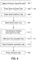
- the route calculation method of the present embodiment is carried out as follows using the route calculation device shown in FIG. 5 , for example.
- the route calculation method of the present embodiment includes an additional information acquisition step (S4) and a speed determination step (S51) as main steps in addition to the steps of the route calculation method of the first embodiment.
- S4 includes a speed information acquisition step (S41), a travel speed acquisition step (S42), and a target speed acquisition step (S43).
- the route calculation method of the present embodiment it is only required that S4, S51, S1, and S32 are performed in this order and S43 is performed after S41 and S42, and the order of other steps is by no means limited and not in particular order.
- S11 to S13 and S32 are performed when it is determined that the difference between the target speed and the travel speed is out of a predetermined range in S51.
- S32 calculates a route that offers the shortest required time as the second route. Except for these points, the route calculation method of the present embodiment is the same as the route calculation method of the first embodiment, and the description regarding the route calculation method of the first embodiment can be referred to.
- speed information of a road section is acquired.
- the speed information of a road section is acquired from the storage unit, for example, the speed information of a road section stored in the storage unit is retrieved and acquired.
- the speed information of a road section is acquired by the communication means, for example, the speed information of a road section is acquired via a communication network.
- the speed information of a road section which has been acquired by the road information acquisition unit may be acquired.
- a target speed is acquired based on the first travel route and the speed information of a road section.
- the target speed the speed information of a road section corresponding to the road on which the mobile station is traveling on the first travel route is acquired, for example.
- S51 it is determined whether the difference between the target speed and the travel speed is within a predetermined range.
- the step returns to S41 or does not advance to S1.
- the step advances to S1.
- S11 to S13 and S32 are performed in the same manner as in the route calculation method of the first embodiment, thereby calculating the second travel route.
- the second travel route that offers the shortest required time for stopping by the branch stations is calculated.
- the difference between the target speed and the travel speed is taken into consideration.
- the route calculation device and the route calculation method of the present embodiment for example, it is possible to improve the work efficiency in the establishment of communication with the branch stations on the route.
- the route calculation device 120 of the present embodiment further includes:
- the route calculation method of the present embodiment further includes the following steps: acquiring a plurality of candidate sequences of stopping by the branch stations; calculating a travel time in a case where the mobile station stops by the branch stations according to each candidate sequence based on the time information of a road section; calculating a delay time until communication between the mobile station and each branch station is established after the mobile station has arrived at the branch station with reference to each candidate sequence based on the communication available hours, the reference time, and the time information of a road section; and calculating a required time with reference to each candidate sequence based on the travel time and the delay time, wherein the route calculation unit calculates the candidate sequence that offers the shortest required time as the second travel route.
- the route calculation method including the candidate sequence acquisition step, the travel time calculation step, the delay time calculation step, and the required time calculation step, for example, the description regarding the route calculation method of the second embodiment can be referred to.
- FIG. 7 is a block diagram showing a route calculation device of the present embodiment.
- a route calculation device 130 of the present embodiment includes a traffic congestion information acquisition unit 44 and a traffic congestion determination unit 52 in addition to the components of the route calculation device of the third embodiment.
- the target speed acquisition unit 43, the speed determination unit 51, the traffic congestion determination unit 52, and the route calculation unit 32 may be installed in a data processing unit 83.
- the traffic congestion determination unit 52 is electrically connected to the traffic congestion information acquisition unit 44; and the communication available hours acquisition unit 11, the reference time acquisition unit 12, and the road information acquisition unit 13 are electrically connected to the speed determination unit 51 and the traffic congestion determination unit 52.
- the communication available hours acquisition unit 11, the reference time acquisition unit 12, and the road information acquisition unit 13 acquire the communication available hours, the reference time, and the time information of a road section, respectively, when it is determined that the difference between the target speed and the travel speed is out of a predetermined range by the speed determination unit 51 and that there is traffic congestion on the first travel route by the traffic congestion determination unit 52. Except for these points, the route calculation device 130 of the present embodiment is the same as the route calculation device 120 of the third embodiment, and the description regarding the route calculation device 120 of the third embodiment can be referred to.
- the traffic congestion information acquisition unit 44 acquires the information on the location of traffic congestion.
- the traffic congestion information acquisition unit 44 can be, for example, the communication means.
- the location of traffic congestion may only be the location of traffic congestion on the first travel route or the location of traffic congestion including the location of traffic congestion on the first travel route, for example. The latter includes the location of traffic congestion on the first travel route and other locations of traffic congestion, for example.
- the other locations of traffic congestion can be the location of traffic congestion that is not on the first travel route.
- the traffic congestion determination unit 52 determines whether there is traffic congestion on the first travel route based on the first travel route and the information on the location of traffic congestion.
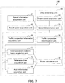
- the route calculation method of the present embodiment is carried out as follows using the route calculation device shown in FIG. 7 , for example.
- the route calculation method of the present embodiment includes a traffic congestion information acquisition step (S44) and a traffic congestion determination step (S52) in addition to the steps of the route calculation method of the third embodiment.
- a determination step (S5) includes S51 and S52.
- the route calculation method of the present embodiment it is only required that S1 and S32 are performed after S4 and S5, S43 is performed after S41 and S42, S51 is performed after S43, and S52 is performed after S44, and the order of other steps is by no means limited and not in particular order.
- S11 to S13 are performed when it is determined that the difference between the target speed and the travel speed is out of a predetermined range in S51 and that there is traffic congestion on the first travel route in S52. Except for these points, the route calculation method of the present embodiment is the same as the route calculation method of the third embodiment, and the description regarding the route calculation method of the third embodiment can be referred to.
- S41 to S43 are performed in the same manner as in the route calculation method of the third embodiment.
- S51 is performed in the same manner as in the route calculation method of the third embodiment.
- S52 it is determined whether there is traffic congestion on the first travel route based on the first travel route and the information on the location of traffic congestion. When there is no traffic congestion on the first travel route, the step returns to S41 or does not advance to S1. In contrast, when there is traffic congestion on the first travel route, the step advances to S1.
- S11 to S13 and S32 are performed in the same manner as in the route calculation method of the third embodiment, thereby calculating the second travel route.
- the information on the location of traffic congestion is also taken into consideration.
- it can be determined whether the difference is unavoidable difference due to the traffic congestion, for example.
- the user can stop by the branch stations with the shortest required time by traveling on the second travel route. Therefore, according to the route calculation device and the route calculation method of the present embodiment, for example, it is possible to improve the work efficiency in the establishment of communication with the branch stations on the route.
- FIG. 9 is a block diagram showing a route calculation device of the present embodiment.
- a route calculation device 140 of the present embodiment includes a speed information acquisition unit 41, an elapsed time acquisition unit 45, a current location acquisition unit 46, a target arrival location calculation unit 47, and a location determination unit 53 in addition to the components of the route calculation device of the first embodiment.
- the target arrival location calculation unit 47, the location determination unit 53, and the route calculation unit 32 may be installed in a data processing unit 84.
- the target arrival location calculation unit 47 is electrically connected to the speed information acquisition unit 41 and the elapsed time acquisition unit 45; the location determination unit 53 is electrically connected to the current location acquisition unit 46 and the target arrival location calculation unit 47; and the communication available hours acquisition unit 11, the reference time acquisition unit 12, and the road information acquisition unit 13 are electrically connected to the location determination unit 53.
- the communication available hours acquisition unit 11, the reference time acquisition unit 12, and the road information acquisition unit 13 acquire the communication available hours, the reference time, and the time information of a road section, respectively, when it is determined that the locational difference between the target arrival location and the current location is out of a predetermined range by the location determination unit 52.
- the route calculation unit 32 calculates a route that offers the shortest required time as the second route. Except for these points, the route calculation device 140 of the present embodiment is the same as the route calculation device 100 of the first embodiment, and the description regarding the route calculation device 100 of the first embodiment can be referred to.
- the elapsed time acquisition unit 45 acquires an elapsed time after the mobile station has started to travel.
- Examples of the elapsed time acquisition unit 45 include well known time measurement units such as timers and stopwatches.
- the elapsed time after the mobile station has started to travel can be, for example, a time elapsed from the time when the mobile station starts traveling.
- the elapsed time may be a time obtained by measuring a time required for the mobile station to pass through each road section, for example.
- the current location acquisition unit 46 acquires a current location.
- the current location acquisition unit 46 can be, for example, a well known positioning unit such as a global positioning system (GPS).
- GPS global positioning system
- the current location can be, for example, the current location of the mobile station.
- the target arrival location calculation unit 47 calculates a target arrival location based on the speed information of a road section and the elapsed time.
- the target arrival location can be, for example, a mathematically predictable location of the mobile station at the elapsed time.
- the location determination unit 53 determines whether the difference between the target arrival location and the current location is out of a predetermined range.
- the predetermined range is not particularly limited, and can be determined appropriately according to the legal speed of a road or the like in the road section in which the mobile station is traveling, for example.
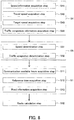
- the route calculation method of the present embodiment is carried out as follows using the route calculation device shown in FIG. 9 , for example.
- the route calculation method of the present embodiment includes an additional information acquisition step (S4) and a location determination step (S53) as main steps in addition to the steps of the route calculation method of the first embodiment.
- S4 includes a speed information acquisition step (S41), an elapsed time acquisition step (S45), a current location acquisition step (S46), and a target arrival location calculation step (S47).
- the route calculation method of the present embodiment it is only required that S4, S53, S1, and S32 are performed in this order and S47 is performed after S41 and S45, and the order of other steps is by no means limited and not in particular order.
- S11 to S13 and S32 are performed when it is determined that the difference between the target arrival location and the current location is out of a predetermined range in S53.
- S32 calculates a route that offers the shortest required time as the second route. Except for these points, the route calculation method of the present embodiment is the same as the route calculation method of the first embodiment, and the description regarding the route calculation method of the first embodiment can be referred to.
- S 41 is performed in the same manner as in the route calculation method of the third embodiment.
- a target arrival location is calculated based on the speed information of a road section and the elapsed time.
- the target arrival location can be calculated by adding a distance calculated based on the average speed of each road section acquired from the speed information of the road section and the elapsed time of each road section to the current location at the time of calculating the first travel route, for example.
- S53 it is determined whether the locational difference between the target arrival location and the current location is out of a predetermined range.
- the step returns to S41 or does not advance to S1.
- the step advances to S1.
- S11 to S13 and S32 are performed in the same manner as in the route calculation method of the first embodiment, thereby calculating the second travel route.
- the route calculation device and the route calculation method of the present embodiment when the locational difference between the target arrival location and the current location is out of a predetermined range, the second travel route that offers the shortest required time for stopping by the branch stations is calculated.
- the locational difference between the target arrival location and the current location is taken into consideration.
- the user can stop by the branch stations with the shortest required time by traveling on the second travel route. Therefore, according to the route calculation device and the route calculation method of the present embodiment, for example, it is possible to improve the work efficiency in the establishment of communication with the branch stations on the route.
- the route calculation device 140 of the present embodiment further includes: a traffic congestion information acquisition unit that acquires information on a location of traffic congestion; and a traffic congestion determination unit that determines whether there is traffic congestion on the first travel route based on the first travel route and the information on a location of traffic congestion, wherein when it is determined that the locational difference between the target arrival location and the current location is out of a predetermined range and that there is traffic congestion on the first travel route, the route calculation unit calculates the second travel route that offers the shortest required time for stopping by the branch stations.
- the route calculation device including the traffic congestion information acquisition unit and the traffic congestion determination unit for example, the description regarding the route calculation device of the fourth embodiment can be referred to.
- the route calculation method of the present embodiment further includes the following steps: acquiring information on a location of traffic congestion; and determining whether there is traffic congestion on the first travel route based on the first travel route and the information on the location of traffic congestion, wherein when it is determined that the locational difference between the target arrival location and the current location is out of a predetermined range and that there is traffic congestion on the first travel route, the second travel route that offers the shortest required time for stopping by the branch stations is calculated in the route calculation step.
- the route calculation method including the traffic congestion information acquisition step and the traffic congestion determination step for example, the description regarding the route calculation method of the fourth embodiment can be referred to.
- FIG. 11 is a block diagram showing a navigation device of the present embodiment.
- a navigation device 200 of the present embodiment includes a route calculation device 100 and a display unit 61.
- the route calculation device 100 is electrically connected to the display unit 61.
- the route calculation device 100 of the present embodiment is the same as the route calculation device 100 of the first embodiment and the description regarding the route calculation device 100 of the first embodiment can be referred to.
- the route calculation device includes the route calculation device 100 of the first embodiment in the present embodiment, it may include any of the route calculation devices of the second to fifth embodiments or a route calculation device configured by combining the route calculation devices of the second to fifth embodiments.
- the display unit 61 displays the first travel route calculated by the route calculation device.
- the display unit is not particularly limited, and examples thereof include various image displays such as liquid crystal displays (LCDs) and cathode-ray tube (CRT) displays.
- LCDs liquid crystal displays
- CRT cathode-ray tube
- the navigation method of the present embodiment is carried out as follows using the route calculation device shown in FIG. 11 , for example.
- the navigation method of the present embodiment includes the route calculation method of the first embodiment (S100) and a display step (S61). In the navigation method of the present embodiment, it is only required that S100 and S61 are performed in this order. S100 is the same as the route calculation method of the first embodiment and the description regarding the route calculation method of the first embodiment can be referred to.
- the route calculation method includes the route calculation method 100 of the first embodiment in the present embodiment, it may include any of the route calculation methods of the second to fifth embodiments or a route calculation method obtained by combining the methods of the second to fifth embodiments.
- the communication available hours of the branch stations are obtained by the route calculation device and the route calculation method, and the first travel route that offers the shortest required time for stopping by the branch stations is calculated based on the communication available hours, the reference time, and the time information of a road section.
- the route that allows a user to arrive at a destination or a stop-off point within a determined time period can be displayed.
- the navigation device and the navigation method of the present embodiment for example, because the user can arrive at a destination or a stop-off point within a determined time period, it is possible to improve the work efficiency in the establishment of communication with the branch stations on the route.
- the display unit displays a warning when the speed determination unit of the route calculation device determines that the difference between the target speed and the travel speed acquired by the route calculation device is out of a predetermined range. Furthermore, in the navigation method of the present embodiment, preferably, a warning is displayed in the display step when it is determined that the difference between the target speed and the travel speed acquired by the route calculation device is out of a predetermined range in the speed determination step of the route calculation method. By displaying a warning, it is possible to notify the operator of the navigation device that the arrival at the next branch station will be too early or too late, for example. These effects can be obtained also in the preferable embodiments described below.
- the navigation device of the present embodiment further includes a travel route determination unit that determines whether the second travel route is different from the first travel route, wherein when the travel route determination unit determines that the second travel route calculated by the route calculation device is different from the first travel route, the display unit displays the second travel route calculated by the route calculation device and a notice that a travel route has changed.
- the navigation method of the present embodiment further includes the following steps: determining whether the second travel route is different from the first travel route, wherein when it is determined that the second travel route calculated by the route calculation method is different from the first travel route in the travel route determination step, the second travel route calculated by the route calculation method and a notice that a travel route has changed are displayed in the display step.
- the display unit displays a warning when the speed determination unit of the route calculation device determines that the difference between the target speed and the travel speed acquired by the route calculation device is out of a predetermined range and the traffic congestion determination unit of the route calculation device determines that there is no traffic congestion on the first travel route. Furthermore, in the navigation method of the present embodiment, preferably, a warning is displayed in the display step when it is determined that the difference between the target speed and the travel speed acquired by the route calculation method is out of a predetermined range in the speed determination step of the route calculation method and that there is no traffic congestion on the first travel route in the traffic congestion determination step of the route calculation method.
- the display unit displays a warning when the location determination unit of the route calculation device determines that the locational difference between the target arrival location and the current location acquired by the route calculation device is out of a predetermined range. Furthermore, in the navigation method of the present embodiment, preferably, a warning is displayed in the display step when it is determined that the locational difference between the target arrival location and the current location acquired by the route calculation method is out of a predetermined range in the location determination step of the route calculation method.
- the display unit displays a warning when the location determination unit of the route calculation device determines that the locational difference between the target arrival location and the current location acquired by the route calculation device is out of a predetermined range and the traffic congestion determination unit of the route calculation device determines that there is no traffic congestion on the first travel route. Furthermore, in the navigation method of the present embodiment, preferably, a warning is displayed in the display step when it is determined that the locational difference between the target arrival location and the current location acquired by the route calculation method is out of a predetermined range in the location determination step of the route calculation method and that there is no traffic congestion on the first travel route in the traffic congestion determination step of the route calculation method.
- the display unit additionally displays the target speed acquired by the route calculation device. Furthermore, in the navigation method of the present embodiment, preferably, the target speed acquired by the route calculation device is additionally displayed in the display step. By displaying the target speed, the operator of the navigation device can always check an optimal speed.
- the route calculation unit of the route calculation device calculates an estimated arrival time of arriving at the next branch station to be stopped by based on the reference time, the first travel route, and the time information of a road section acquired by the route calculation device, and the display unit displays the estimated arrival time. Furthermore, in the navigation method of the present embodiment, preferably, an estimated arrival time of arriving at the next branch station to be stopped by is calculated based on the reference time, the first travel route, and the time information of a road section acquired by the route calculation method, and the estimated arrival time is displayed in the display step.
- the navigation device of the present embodiment further includes a communication range acquisition unit that acquires the communication range of the branch station, wherein the display unit displays the communication range of the branch station.
- the display unit displays the branch stations, and more preferably, the display unit displays the branch stations with which communication has not been completed out of the branch stations.
- the communication range acquisition unit can be, for example, the communication means.
- the navigation method of the present embodiment further includes following step: acquiring a communication range of the branch station, wherein the communication range of the branch station is displayed in the display step.
- the branch stations are displayed in the display step, and more preferably, the branch stations with which communication has not been completed out of the branch stations are displayed in the display step.
- the display unit displays the number of branch stations with which communication has not been completed out of the branch stations. Furthermore, in the navigation method of the present embodiment, preferably, the number of branch stations with which communication has not been completed out of the branch stations is displayed in the display step.
- the seventh embodiment discloses a configuration that uses a navigation device for establishing communication with a signal which is a branch station.
- FIG. 13 is a block diagram showing a navigation device of the seventh embodiment.
- a navigation device 210 of the present embodiment includes a computing unit 2, a storage unit 3, a positioning unit 4, a display unit 5, and a vehicle information acquisition unit 6.
- the computing unit 2 is electrically connected to the storage unit 3, the positioning unit 4, the display unit 5, and the vehicle information acquisition unit 6.
- a vehicle is equipped with the navigation device 210, and the navigation device 210 is physically connected to the vehicle.
- the navigation device 210 is physically connected to the vehicle in the present embodiment, the present invention may have a configuration in which the navigation device 210 is not physically connected such as a portable terminal.
- signal information (the number of target signals to be communicated, location information of a signal, a communication area (communication range) of a signal, communication hours of a signal, etc.), which is branch station information; a candidate sequence which is a sequence of stopping by a communication range (hereinafter, also referred to as a "communication area") of a signal; and road information (a road map, a passing time of a road section, driving time information based on the passing time of a road section, connection information for each road section, an average speed of a road section, distance information of a road section, etc.) are stored in the storage unit 3.
- the positioning unit 4 acquires the location information of the navigation device 210, i.e., the global positioning system (GPS) information including the location information of the vehicle, a current time, and the like from a GPS satellite.
- GPS global positioning system
- the display unit 5 displays the road map information and the like stored in the storage unit 3.
- the display unit 5 is described in detail with reference to FIG. 14.
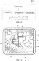
- FIG. 14 is a view showing the interface of the navigation device 210.
- the display unit 5 displays a map 71, a vehicle location 72 of a vehicle equipped with the navigation device 210, a route (first travel route) 73 which a vehicle should follow, a signal location 74 of a target signal to be communicated, and target information 75.
- the map 71 is displayed based on the traffic information stored in the storage unit 3.
- the scale of the map 71 is fixed, and the map can be scaled up or scaled down in response to the operation of a user.
- the vehicle location 72 of a vehicle equipped with the navigation device 210 is displayed on the map 71 by acquiring a GPS signal from the positioning unit 4 and calculating the location of the vehicle at the time of receiving the GPS signal.
- the route 73 which a vehicle should follow the route calculated by the computing unit 2 is displayed. The route calculation method is described in detail below.
- the signal locations 74 preliminarily stored in the storage unit 3 are displayed on the map 71.
- the target information 75 includes the information acquired by the computing unit 2 and the information stored in the storage unit 3.
- Examples of the target information 75 include a target speed of a vehicle, a communication range of a signal, a target arrival time of arriving at a communication range of a signal, communication available hours of a signal with which communication should be established, a standby time until the communication with a signal with which communication should be established becomes available, a target arrival time (next target arrival time) of arriving at a communication range of a signal with which communication should be established next, and the number of signals with which communication should be established.
- the vehicle information acquisition unit 6 acquires vehicle speed information, VICS (registered trademark) information received by a vehicle, road traffic congestion information, and road accident information.
- VICS registered trademark
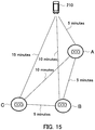
- FIG. 15 is a view showing an example of a case where there are three signals, namely, signals A, B, and C.
- the route calculation method is described with reference to a case where there are three signals A, B, and C.
- the location of a vehicle is acquired from the GPS.
- the required times with respect to all possible combinations of the communication sequences of signals A, B, and C are calculated based on the location information of signals A, B, and C preliminarily stored in the storage unit 3 and the location information of the vehicle acquired from the positioning unit 4. Then, the communication sequence that offers the shortest required time out of the calculated required times is selected as the first travel route.
- route 1 the vehicle travels to the communication area of the signal A and communicates with the signal A in the communication area of the signal A. After the vehicle has communicated with the signal A in the communication area of the signal A, the vehicle travels from the communication area of the signal A to the communication area of the signal B and communicates with the signal B in the communication area of the signal B. After the vehicle has communicated with the signal B in the communication area of the signal B, the vehicle travels from the communication area of the signal B to the communication area of the signal C and communicates with the signal C in the communication area of the signal C.
- the required time for the route 1 is calculated as follows.
- the travel time of the vehicle from the current location of the vehicle to the communication area of the signal A is calculated as 5 minutes.
- the travel time of the vehicle from the communication area of the signal A to the communication area of the signal B is calculated as 5 minutes.
- the travel time of the vehicle from the communication area of the signal B to the communication area of the signal C is calculated as 5 minutes.
- the required time for the whole journey is calculated as 15 minutes.
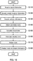
- FIG. 16 is a flowchart showing the route calculation by the computing unit 2.
- step (hereinafter, S) 110 location information of each signal to be communicated, a communication area of each signal, and communication available hours of each signal are acquired from the storage unit 3.
- the computing unit 2 acquires the location information of the navigation device 210 based on the GPS information received by the positioning unit 4.
- the computing unit 2 acquires the passing time of a road section, i.e., the driving time information between the signals; the connection information for each road section; and the (average) speed of a road section from the storage unit 3.
- the computing unit 2 acquires a candidate communication sequence (candidate sequence) from the storage unit 3.
- a candidate communication sequence candidate communication sequence
- all possible communication sequences of signals with which communication is established are acquired as candidate communication sequences.
- the acquisition of the candidate communication sequence is not limited to the acquisition of all possible communication sequences, but a predetermined number of communication sequences may be acquired as the candidate communication sequences.
- the computing unit 2 calculates the required time in a case where the vehicle travels according to each candidate communication sequence based on the communication area of each signal acquired in S110, the location information of the navigation device 210 acquired in S120, and the average speed of a road section and the distance information of a road section acquired in S130. Specifically, the computing unit 2 calculates the route information that offers the shortest road distance to the communication area of the first signal in the candidate communication sequence based on the location information of the navigation device 210 and the distance information of a road section. Then, the time required for arriving at the communication area of the first signal in the candidate communication sequence is calculated based on the route information that offers the shortest calculated distance and the average speed of a road section.
- the route information that offers the shortest road distance from the communication area of the first signal in the candidate communication sequence to the communication area of the second signal in the candidate communication sequence is calculated.
- the time required for traveling from the communication area of the first signal in the candidate communication sequence to the communication area of the second signal in the candidate communication sequence is calculated based on the route information that offers the shortest calculated distance and the average speed of a road section.
- the required times between the signals can be acquired by repeating the same procedure for the number of signals in the candidate communication sequence. By summing the calculated required times, the entire required time for the candidate communication sequence is calculated.
- each required time may be calculated based on the passing time of a road section stored in the storage unit 3, i.e., the driving time information between the signals.
- the required time is calculated based on the average speed of a road section and the distance information of the road section in S150 of the present embodiment, the passing time of a road section may be used as the required time.
- the computing unit 2 calculates an estimated arrival time of arriving at the communication area of a signal by adding each required time acquired in S150 to the current time acquired by the positioning unit 4.
- the computing unit 2 calculates a standby time (standby time due to communication unavailable hours) until communication is established based on the estimated arrival time calculated and the communication available hours of each signal acquired in S110 with reference to the time when the vehicle arrives at the communication area of the signal.
- the computing unit 2 selects the candidate communication sequence that offers a route in which the time obtained by adding the standby time calculated in S160 to the entire required time for the candidate communication sequence calculated in S150 is the shortest as the first travel route (hereinafter, referred to as "shortest route information").
- the route selected by the computing unit 2 in S170 and the average speed of a road section used for calculating the route as a target speed which the vehicle should follow are displayed on the display unit 5. Furthermore, the target arrival time of arriving at the communication area, the communication available hours, and the next target arrival time are displayed on the display unit 5 as the target information 75.
- FIG. 15 A specific example of the route calculation method is described with reference to FIGs. 15 and 17 and Table 2. As shown in FIG. 15 , the route calculation method is described with reference to a case where there are three signals, namely, signals A, B, and C. As shown in FIG. 15 , the route calculation method is described with reference to a case where there are three signals, namely, signals A, B, and C. As shown in FIG. 15 , the route calculation method is described with reference to a case where there are three signals, namely, signals A, B, and C. As shown in FIG.
- the required time from the location of the vehicle to the communication area of the signal A is assumed to be 5 minutes
- the required time from the location of the vehicle to the communication area of the signal B is assumed to be 10 minutes
- the required time from the location of the vehicle to the signal C is assumed to be 15 minutes
- the required time from the communication area of the signal A to the communication area of the signal B is assumed to be 5 minutes
- the required time from the communication area of the signal A to the communication area of the signal C is assumed to be 10 minutes
- the required time from the communication area of the signal B to the communication area of the signal C is assumed to be 5 minutes.
- FIG. 17 is a view showing the communication available hours of the signals.
- the communication available hours of the signal A are 30 minutes.
- the signal A is configured such that its communication periodically becomes available after 30 minutes has passed from the communication available hours.
- the communication available hours of the signal B are 20 minutes.
- the signal B is configured such that its communication periodically becomes available after 20 minutes has passed from the communication available hours.
- the communication available hours of the signal C are 10 minutes.
- the signal C is configured such that its communication periodically becomes available after 10 minutes has passed from the communication available hours.
- Table 2A is a table showing the arrival time at each branch station (signal) in the case of applying the present invention to the seventh embodiment of FIG. 15 and the communication available hours of each branch station.
- Table 2B is a table showing the required time and the standby time at each branch station. In the present embodiment, the time for communication between the navigation device 210 and each signal is assumed to be 0 minute.
- the first branch station, the second branch station, and the third branch station respectively represent the first signal, the second signal, and the third signal which the vehicle will pass.
- the first branch station, the second branch station, and the third branch station are the signal A, the signal B, and the signal C, respectively.
- the required time (5 minutes) from the location of the vehicle to the communication area of the signal A, the required time (5 minutes) from the communication area of the signal A to the communication area of the signal B, and the required time (5 minutes) from the communication area of the signal B to the communication area of the signal C are summed to output the required time (15 minutes) for the whole journey of route 1.
- the required time may be calculated based on the communication area of the signal, the location information of the vehicle, and the vehicle speed information, for example.
- the required time (5 minutes) from the location of the vehicle to the communication area of the signal A is calculated based on the communication area of the signal A which is the first signal in the candidate communication sequence, the vehicle location information, and vehicle speed information.
- the required time (5 minutes) from the communication area of the signal A to the communication area of the signal B is calculated based on the communication area of the signal A, the communication area of the signal B with which communication is established next, and the vehicle speed information.
- the required time (5 minutes) from the communication area of the signal B to the communication area of the signal C is calculated based on the communication area of the signal B, the communication area of the signal C with which communication is established next, and the vehicle speed information. Then, the calculated required times are summed to output the required time (15 minutes) for the whole journey of route 1.
- the computing unit 2 calculates the standby time (25 minutes) until the communication with the signal A becomes available based on the calculated estimated arrival time (14:35) and the acquired communication available hours of the signal A (15:00 to 15:30). Furthermore, by adding the travel time (5 minutes) from the communication area of the signal A to the communication area of the signal B to the start time of the communication available hours of the signal A (15:00), the time of arriving at the communication area of the signal B (15:05) is calculated.
- the computing unit 2 calculates the standby time (5 minutes) until the communication with the signal B becomes available based on the calculated estimated arrival time (15:05) and the acquired communication available hours of the signal B (15:10 to 15:30). Then, by adding the travel time (5 minutes) from the communication area of the signal B to the communication area of the signal C to the start time of the communication available hours of the signal B (15:10), the time of arriving at the communication area of the signal C (15:15) is calculated.
- the computing unit 2 calculates the standby time (0 minute) until the communication with the signal C becomes available based on the calculated estimated arrival time (15:15) and the acquired communication available hours of the signal C (15:10 to 15:20). By summing the calculated standby times, the delay time (hereinafter, also referred to as the "entire standby time”) (30 minutes) is calculated.
- the time obtained by summing the calculated required time (15 minutes) for the whole journey of route 1 and the entire standby time (30 minutes) is calculated as the entire required time for the candidate communication sequence route 1 (hereinafter, also referred to as the "completion time of the whole journey") (45 minutes).
- route 2 to route 6 by summing the entire travel time and the entire standby time, the entire required time for each of the candidate communication sequences is calculated. Then, the route that offers the shortest required time out of the candidate communication sequences (route 4, 30 minutes) is selected as the first travel route.
- route 1 with which the completion time of the whole journey is in fact 45 minutes is selected.
- route 4 with which the completion time of the whole journey is 30 minutes can be selected.
- the eighth embodiment discloses a configuration that establishes communication with vibration sensors (acoustic sensors), which are the branch stations, buried underground and provided on water and sewerage pipes and uses a navigation device for collecting sensor information such as vibration data acquired by the vibration sensors.
- vibration sensors acoustic sensors
- the navigation device of the eighth embodiment is described in detail with reference to FIGs. 18 to 20 .
- FIG. 18 is a block diagram showing a navigation device 220 of the eighth embodiment.
- the navigation device 220 of the present embodiment includes a computing unit 2, an information storage unit 3, a positioning unit 4, a display unit 5, a vehicle information acquisition unit 6, and a transceiver 7.
- a vehicle is equipped with the navigation device 220.
- the computing unit 2 is electrically connected to the storage unit 3, the positioning unit 4, the display unit 5, and the vehicle information acquisition unit 6; and the transceiver 7 is electrically connected to the storage unit 3.
- the navigation device 220 includes the transceiver 7. Except for this, the navigation device 220 of the present embodiment has the same configuration as the navigation device 210 of the seventh embodiment. In the present embodiment, the description of the seventh embodiment can be referred to by replacing the "signal" with the "sensor".
- the transceiver 7 communicates with a vibration sensor (not shown) which is provided on a pipe for detecting water leakage from the pipe in a water and sewerage system buried underground and receives the vibration data of the pipe acquired by the vibration sensor. The received data is stored in the storage unit 3. Then, the information on a sensor with which communication has been completed is stored in the storage unit 3.
- FIG. 19 is a view showing the interface screen of the navigation device 220.
- a sensor location 76 of a sensor buried underground and a sensor communication area 77 are displayed on the interface screen.
- the sensor is buried underground.
- the sensor is invisible to an operator of the vehicle equipped with the navigation device 220 and there is a possibility that the operator cannot find the real sensor location 76 and the real sensor communication area 77.
- the arrival at the sensor communication area 77 may be notified by a sound or a voice.
- a warning 78 which tells the operator to "speed up" is displayed.
- FIG. 20 is a flowchart showing the route calculation of the navigation device 220.
- S110 to S170 are described in the seventh embodiment, and therefore the description is omitted.
- the shortest route information is selected in S170, and thereafter the step advances to S180.
- the route acquired by the computing unit 2 a target time of arriving at the communication area of the sensor with which communication is established next, and the number of sensors with which communication has not been established yet are displayed on the display unit 5 as the target information 75.
- the computing unit 2 calculates the number of sensors with which communication has not been established yet based on the number of sensors with which communication should be established and the number of sensors with which communication has been completed stored in the storage unit 3. Thereafter, the step advances to S190.
- the target speed used for the route calculation and the vehicle speed information acquired by the vehicle information acquisition unit 6, i.e., the current travel speed of the navigation device 220 are acquired. Then, it is determined whether the absolute value of the difference therebetween is equal to or more than ⁇ km/h. When the absolute value of the difference is equal to or more than ⁇ km/h, the step advances to S200. On the other hand when the absolute value of the difference is less than ⁇ km/h, the step advances to S210.
- a predetermined value ⁇ is set such that the vehicle arrives at the communication area before or after the communication available hours of the sensor, for example.
- ⁇ is a fixed value (constant) in the present embodiment, ⁇ may be a variable value (variable) and ⁇ may be calculated successively while the vehicle is travelling. Furthermore, although the determination was made by comparing with a reference value in the present embodiment, the determination may be made by comparing with a predetermined numerical range (predetermined range) on the basis of whether the speed satisfied the numerical range, for example.
- a target arrival location (hereinafter, referred to as a "target location") where the navigation device 220 should be present may be calculated based on the current time acquired from the vehicle information acquisition unit 6 and it may be determined whether to give a warning based on the difference between the target location and the location information of the navigation device 220 (hereinafter, also referred to as a "current location") acquired by the positioning unit 4 or it may be determined whether to give a warning based on the target location, the current location, and the passing time of a road section.
- S210 it is determined whether the number of sensors with which communication has not been established yet calculated in S180 is 0. When the number of sensors with which communication has not been established yet is not 0, the step returns to S180. When the number of sensors with which communication has not been established yet is 0, the procedure in the flowchart is terminated.
- the ninth embodiment discloses a configuration that establishes communication with sensors buried underground and uses a navigation device for collecting sensor information acquired by the sensors.
- the navigation device of the ninth embodiment is described in detail with reference to FIGs. 21 and 22 .
- the navigation device of the ninth embodiment has the same configuration as the navigation device shown in FIG. 18 described in the eighth embodiment, and therefore the description is omitted.
- the transceiver 7 communicates with a vibration sensor (not shown) which is provided on a pipe for detecting water leakage from the pipe in a water and sewerage system buried underground and receives the vibration data of the pipe acquired by the vibration sensor.
- the received data is stored in the storage unit 3.
- the information on a sensor with which communication has been completed is stored in the storage unit 3.
- FIG. 21 is a view showing the interface screen of the navigation device 220.
- the sensor location 76 of a sensor buried underground and the sensor communication area 77 are displayed on the interface screen.
- a newly selected route 70 is displayed when it is determined that the vehicle cannot arrive at the communication area within the target communication available hours.
- the navigation device 220 of the present embodiment has the same configuration as the navigation device of the eighth embodiment. In the present embodiment, the descriptions of the seventh embodiment and the eighth embodiment can be referred to by replacing the "signal" with the "sensor".
- Examples of the case where it is determined that the vehicle cannot arrive at the communication area within the target communication available hours include the case where it is determined that the difference between the target speed and the travel speed is out of a predetermined range and the case where it is determined that the difference between the target arrival location and the location information of the mobile station is out of a predetermined range.
- FIG. 22 is a flowchart showing the route calculation of the navigation device 220.
- the flowchart of the control of FIG. 22 is started.
- S110 to S170 are described in the seventh embodiment, and therefore the description is omitted.
- the route is selected in S170, and thereafter the step advances to S220.
- the computing unit 2 determines whether the selected route is different from the previous route. When the selected route is the same as the previous route, the step advances to S180. When the selected route is different from the previous route, the step advances to S230.
- the route acquired by the computing unit 2 in S170, a target arrival time of arriving at the communication area of the sensor with which communication is established next, and the number of sensors with which communication has not been established yet are displayed on the display unit 5 as the target information 75. Furthermore, a rerouting notice 79 that notifies a user that rerouting has been performed is displayed on the display unit 5.
- the computing unit 2 calculates the number of sensors with which communication has not been established yet based on the number of sensors with which communication should be established and the number of sensors with which communication has been completed stored in the storage unit 3. Thereafter, the step advances to S190.
- the route selected this time a target time of arriving at the communication area, the next target arrival time, the number of sensors with which communication has not been established yet, and a notice that the route has changed are displayed on the display unit 5 as the target information 75.
- the computing unit 2 calculates the number of sensors with which communication has not been established yet based on the number of sensors with which communication should be established and the number of sensors with which communication has been completed stored in the storage unit 3. Thereafter, the step advances to S190.
- the target speed used for the route calculation and the current vehicle speed information acquired by the vehicle information acquisition unit 6 are acquired. Then, it is determined whether the absolute value of the difference therebetween is equal to or more than ⁇ km/h. When the absolute value of the difference is equal to or more than ⁇ km/h, the step advances to S120 to reselect the route. On the other hand, when the absolute value of the difference is less than ⁇ km/h, the step advances to S210.
- ⁇ may be a variable, and the step may advance to S120 when the target speed exceeds the legal speed of a road section on which the vehicle is currently driving.
- it is determined whether to advance to S120 or S210 based on the target speed and the current vehicle speed information in the present embodiment for example, it may be determined whether to advance to S120 or S210 based on the difference between the target location and the current location or it may be determined whether to advance to S120 or S210 based on the target location, the current location, and the passing time of a road section.
- S210 it is determined whether the number of sensors with which communication has not been established yet calculated in S180 or S230 is 0, i.e., it is determined whether communication has been completed with all sensors.
- the step returns to S190.
- the procedure in the flowchart is terminated.
- the flowchart is terminated when the number of sensors with which communication has not been established yet is 0 in the present embodiment, for example, the flowchart may be terminated when the number of sensors with which communication has not been established yet is 1 or less. There is not much merit of rerouting when the number of sensors with which communication has not been established yet is 1 or less, for example.
- the tenth embodiment discloses a configuration that establishes communication with sensors, which are the branch stations, buried underground and uses a navigation device for collecting sensor information acquired by the sensors.
- the navigation device of the tenth embodiment is described in detail with reference to FIG. 23 .
- the navigation device and the interface of the navigation device of the tenth embodiment has the same configuration as the navigation device shown in FIG. 18 described in the eighth embodiment, and therefore the description is omitted.
- the descriptions of the seventh embodiment to the ninth embodiment can be referred to by replacing the "signal" with the "sensor".
- the navigation device 220 of the present embodiment detects whether the delay is a delay (unavoidable delay) caused by traffic congestion or a delay (avoidable delay) by other reasons.
- the delay is caused by traffic congestion delay (unavoidable delay)
- the navigation device displays a newly selected route.
- the delay is caused by other reasons (avoidable delay)
- the navigation device displays a warning.
- FIG. 23 is a flowchart showing the route calculation of the navigation device 220.
- S110 to S230 are described in the foregoing embodiments (seventh embodiment to the ninth embodiment), and therefore the description is omitted.
- the target speed used for the route calculation and the current vehicle speed information acquired by the vehicle information acquisition unit 6 are acquired. Then, it is determined whether the absolute value of the difference therebetween is equal to or more than ⁇ km/h. When the absolute value of the difference is equal to or more than ⁇ km/h, the step advances to S240. On the other hand, when the absolute value of the difference is less than ⁇ km/h, the step advances to S210.
- ⁇ is a predetermined constant in the present embodiment, ⁇ may be a variable and may be varied according to the legal speed, for example.
- traffic congestion information acquired by the vehicle information acquisition unit 6 is acquired and it is determined whether there is traffic congestion on the route selected by the computing unit 2 in S170 based on the acquired traffic congestion information.
- the step returns to S120 to perform the route calculation again.
- the step advances to S200 to display a warning 78 on the display unit 5 as shown in FIG. 23 .
- a new route can be displayed when there is an unavoidable delay. Furthermore, when there is an avoidable delay, by giving a warning, it is possible to provide an operator with supports according to situations. Thus, it is possible to improve the efficiency of the operation.
- the program of the present embodiment is a program that can execute the route display method according to the present invention or the navigation method according to the present invention on a computer.
- the program of the present embodiment may be recorded in a recording medium, for example.
- the recording medium is not particularly limited, and examples thereof include random access memories (RAMs), read-only memories (ROMs), hard disks (HDs), optical disks, and floppy (registered trademark) disks (FDs).
- FIG. 24 shows an example of the configuration of a communication system using the navigation device of the present invention.
- FIG. 24 is a conceptual diagram of the communication system of the present embodiment.
- the communication system includes branch station 8a, 8b, and 8c and a vehicle 9 equipped with the navigation device 220.
- the branch stations 8a, 8b, and 8c are provided at places X, Y, and Z, respectively.
- the branch station 8a includes a storage unit 91a and a transmission unit 92a.
- the storage unit 91a is connected.to the transmission unit 92a.
- the branch station 8b includes a storage unit 91b and a transmission unit 92b.
- the storage unit 91b is connected to the transmission unit 92b.
- the branch station 8c includes a storage unit 91c and a transmission unit 92c.
- the storage unit 91c is connected to the transmission unit 92c.
- the transmission units 92a, 92b, and 92c transmit data to the transceiver 7 of the navigation device 220 via wireless communication 93a, 93b, and 93c, respectively.
- the sensor (not shown) of the branch station 8a collects measured data.
- the measured data is stored in the storage unit 91a.
- the transmission unit 92a transmits the data to the transceiver 7 of the navigation device 220 mounted on the vehicle 9 via the wireless communication 93a.
- data is transmitted to the transceiver 7 of the navigation device 220 mounted on the vehicle 9 in the same manner as described above.
- the vehicle 9 has to make rounds of the places where the branch stations 8a, 8b, and 8c are placed. Hence, the vehicle 9 travels the places X, Y, and Z according to the travel route selected by the navigation device 220.
- the communication system of the present embodiment it is possible to select the route that allows a user to complete the operation with shorter time than the case of calculating the required time for a route without considering the communication available hours.
- the measured data can be retrieved efficiently.
- the seventh embodiment to the tenth embodiment and the twelfth embodiment each have a configuration that a vehicle establishes communication.
- the use of the route calculation device and the navigation device of the present invention is not limited to the use in a vehicle.
- the route calculation device and the navigation device of the present invention may have a configuration that communication is established by a walker using a portable terminal such as a cellular phone, for example.
- the application of the present invention is not limited to a vehicle, and may be applied to transports such as aircrafts, helicopters, and ships, for example.
- a route calculation device comprising:
- the route calculation device according to supplementary note 1, further comprising:
- the route calculation device according to supplementary note 1 or 2, further comprising:
- the route calculation device according to supplementary note 3, further comprising:
- the route calculation device according to supplementary note 1 or 2, further comprising:
- the route calculation device further comprising:
- a navigation device comprising:
- the navigation device according to supplementary note 7, wherein when the speed determination unit of the route calculation device determines that the difference between the target speed and the travel speed acquired by the route calculation device is out of a predetermined range, the display unit displays a warning.
- the navigation device according to supplementary note 7, further comprising:
- the navigation device according to supplementary note 7, wherein when the speed determination unit of the route calculation device determines that the difference between the target speed and the travel speed acquired by the route calculation device is out of a predetermined range and the traffic congestion determination unit of the route calculation device determines that there is no traffic congestion on the first travel route, the display unit displays a warning.
- the navigation device according to supplementary note 7, wherein when the location determination unit of the route calculation device determines that the locational difference between the target arrival location and the current location acquired by the route calculation device is out of a predetermined range, the display unit displays a warning.
- the navigation device according to supplementary note 7, wherein when the location determination unit of the route calculation device determines that the locational difference between the target arrival location and the current location acquired by the route calculation device is out of a predetermined range and the traffic congestion determination unit of the route calculation device determines that there is no traffic congestion on the first travel route, the display unit displays a warning.
- the navigation device according to any one of supplementary notes 7 to 12, wherein the display unit additionally displays the target speed acquired by the route calculation device.
- the navigation device according to any one of supplementary notes 7 to 13, wherein the route calculation unit of the route calculation device calculates an estimated arrival time of arriving at a next branch station to be stopped by based on the reference time, the first travel route, and the time information of a road section acquired by the route calculation device, and the display unit displays the estimated arrival time.
- the navigation device according to any one of supplementary notes 7 to 14, further comprising:
- the navigation device according to supplementary note 15, wherein the display unit displays the branch stations.
- the navigation device according to supplementary note 15 or 16, wherein the display unit displays a branch station with which communication has not been completed out of the branch stations.
- the navigation device according to any one of supplementary notes 15 to 17, wherein the display unit displays the number of branch stations with which communication has not been completed out of the branch stations.
- a route calculation method comprising following steps:
- a navigation method comprising:
- the navigation method wherein when it is determined that the difference between the target speed and the travel speed acquired by the route calculation method is out of a predetermined range in the speed determination step of the route calculation method and that there is no traffic congestion on the first travel route in the traffic congestion determination step of the route calculation method, a warning is displayed in the display step.
- the navigation method wherein when it is determined that the locational difference between the target arrival location and the current location acquired by the route calculation method is out of a predetermined range in the location determination step of the route calculation method and that there is no traffic congestion on the first travel route in the traffic congestion determination step of the route calculation method, a warning is displayed in the display step.
- a program that can execute the route calculation method according to any one of supplementary notes 19 to 24 or the navigation method according to any one of supplementary notes 25 to 36 on a computer.
- a computer-readable recording medium recorded with the program according to supplementary note 37.
- a communication system comprising:
- the present invention can be applied, for example, to on-vehicle navigation devices, portable terminals, and the like.
Landscapes
- Engineering & Computer Science (AREA)
- Radar, Positioning & Navigation (AREA)
- Remote Sensing (AREA)
- Physics & Mathematics (AREA)
- General Physics & Mathematics (AREA)
- Business, Economics & Management (AREA)
- Human Resources & Organizations (AREA)
- Automation & Control Theory (AREA)
- Economics (AREA)
- Mathematical Physics (AREA)
- Strategic Management (AREA)
- Entrepreneurship & Innovation (AREA)
- Development Economics (AREA)
- Game Theory and Decision Science (AREA)
- Marketing (AREA)
- Operations Research (AREA)
- Quality & Reliability (AREA)
- Tourism & Hospitality (AREA)
- General Business, Economics & Management (AREA)
- Theoretical Computer Science (AREA)
- Computer Networks & Wireless Communication (AREA)
- Signal Processing (AREA)
- Navigation (AREA)
- Traffic Control Systems (AREA)
Abstract
Description
- The present invention relates to a route calculation device, a navigation device, a route calculation method, a navigation method, and a communication system.
- There is a car navigation device that calculates an optimal route for a destination and stop-off points input by a user (Patent Document 1). There is an invention in which working data is stored in a car navigation device and the status of the work is automatically updated when the car arrives at a target place in monitoring or the like for maintenance of gas main pipes (Patent Document 2). Here, there is a need for a car to stop by plural branch stations (devices that collect information and transmit the information to a device with which communication is established) and collect information while traveling. Furthermore, power saving by intermittently operating branch stations is now under consideration.
-
- Patent Document 1:
-
JP 2007-281742 A - Patent Document 2:
-
JP 2008-065421 A - In the above-described related arts, routes are determined simply based on the traffic information and the geographic locations of destinations and stop-off points. Thus, there was a problem that a user sometimes cannot arrive at a destination or a stop-off point within a determined time period. Furthermore, in a case where a car or the like stops by plural branch stations and collects information, when a branch station is not in operating hours (hereinafter, also referred to as "communication available hours"), for example, there is a time for waiting until the branch station starts operating, and this causes additional work (e.g. to go there again for collecting information at another date), resulting in decrease in work efficiency. Hence, the present invention is intended to provide a route calculation device, a navigation device, a route calculation method, and a navigation device that can calculate a route that allows a user to arrive at a destination or a stop-off point within a determined time period.
- In order to achieve the above object, the present invention provides a route calculation device including: a communication available hours acquisition unit that acquires communication available hours of a plurality of branch stations that establish communication with a mobile station; a reference time acquisition unit that acquires a reference time; a road information acquisition unit that acquires time information of a road section; and a route calculation unit that calculates a first travel route that offers a shortest required time for stopping by the branch stations based on the communication available hours, the reference time, and the time information of a road section.
- The present invention also provides a navigation device including; the route calculation device according to the present invention, including: the communication available hours acquisition unit; the reference time acquisition unit; the road information acquisition unit; and the route calculation unit; and a display unit, wherein the display unit displays the first travel route calculated by the route calculation device.
- The present invention also provides a route calculation method including following steps: acquiring communication available hours of a plurality of branch stations that establish communication with a mobile station; acquiring a reference time; acquiring time information of a road section; and calculating a first travel route that offers a shortest required time for stopping by the branch stations based on the communication available hours, the reference time, and the time information of a road section.
- The present invention also provides a navigation method, including: the route calculation method according to the present invention including: the communication available hours acquisition step; the reference time acquisition step; the road information acquisition step; and the route calculation step; and following step: displaying, wherein the first travel route calculated by the route calculation method is displayed in the display step.
- The present invention also provides a program that can execute the route calculation method according to the present invention or the navigation method according to the present invention on a computer.
- The present invention also provides a recording medium recorded with the program according to the present invention.
- The present invention also provides a communication system including: a plurality of branch stations each communicatable within a specific area; and a mobile station that establishes communication with the branch stations, wherein the mobile station can establish communication with the communicatable branch stations via wireless communication, the branch station includes a storage unit that stores data and a transmission unit that transmits the data stored in the storage unit to the mobile station, and the mobile station includes the navigation device according to the present invention and communication means that establishes communication with the branch stations.
- According to the present invention, a route that allows a user to arrive at a destination or a stop-off point within a determined time period can be calculated. Furthermore, according to the present invention, for example, because the user can arrive at a destination or a stop-off point within a determined time period, it is possible to improve the work efficiency in the establishment of communication with the branch stations on the route.
-
- [
FIG. 1] FIG. 1 is a block diagram showing a route calculation device of the first embodiment. - [
FIG. 2] FIG. 2 is a flowchart showing a route calculation method of the first embodiment. - [
FIG. 3] FIG. 3 is a block diagram showing a route calculation device of the second embodiment. - [
FIG. 4] FIG. 4 is a flowchart showing a route calculation method of the second embodiment. - [
FIG. 5] FIG. 5 is a block diagram showing a route calculation device of the third embodiment. - [
FIG. 6] FIG. 6 is a flowchart showing a route calculation method of the third embodiment. - [
FIG. 7] FIG. 7 is a block diagram showing a route calculation device of the fourth embodiment. - [
FIG. 8] FIG. 8 is a flowchart showing a route calculation method of the fourth embodiment. - [
FIG. 9] FIG. 9 is a block diagram showing a route calculation device of the fifth embodiment. - [
FIG. 10] FIG. 10 is a flowchart showing a route calculation method of the fifth embodiment. - [
FIG. 11] FIG. 11 is a block diagram showing a route calculation device of the sixth embodiment. - [
FIG. 12] FIG. 12 is a flowchart showing a route calculation method of the sixth embodiment. - [
FIG. 13] FIG. 13 is a block diagram showing a navigation device of the seventh embodiment. - [
FIG. 14] FIG. 14 is a view showing an interface of a navigation device of the seventh embodiment. - [
FIG. 15] FIG. 15 is a view showing an example of a case where there are three signals in the seventh embodiment. - [
FIG. 16] FIG. 16 is a flowchart showing route calculation of a navigation device of the seventh embodiment. - [
FIG. 17] FIG. 17 is a view showing communication hours of signals in the seventh embodiment. - [
FIG. 18] FIG. 18 is a block diagram showing a navigation device of the eighth embodiment. - [
FIG. 19] FIG. 19 is a view showing an interface of a navigation device of the eighth embodiment. - [
FIG. 20] FIG. 20 is a flowchart showing route calculation of a navigation device of the eighth embodiment. - [
FIG. 21] FIG. 21 is a view showing an interface of a navigation device of the ninth embodiment. - [
FIG. 22] FIG. 22 is a flowchart showing route calculation of a navigation device of the ninth embodiment. - [
FIG. 23] FIG. 23 is a flowchart showing route calculation of a navigation device of the tenth embodiment. - [
FIG. 24] FIG. 24 is a conceptual diagram of a communication system of the twelfth embodiment. - The route calculation device, the navigation device, the route calculation method, the navigation method, and the communication system according to the present invention are described below with reference to drawings. The present invention, however, is not limited by the following description. Descriptions of embodiments can be referred to one another, unless otherwise stated. Furthermore, configurations of embodiments can be combined, unless otherwise stated. Hereinafter, in
FIGs. 1 to 24 , identical parts are indicated with identical numerals and symbols, and the descriptions of the identical parts may be omitted. Furthermore, for convenience in explanation, the structure of each component shown inFIGs. 1 to 24 may be appropriately simplified, and the size, the ratio, and the like of components may be schematically shown and different from actual ones. -
FIG. 1 is a block diagram showing a route calculation device of the present embodiment. As shown inFIG. 1 , aroute calculation device 100 of the present embodiment includes a communication availablehours acquisition unit 11, a referencetime acquisition unit 12, a roadinformation acquisition unit 13, and aroute calculation unit 31. As shown inFIG. 1 , theroute calculation unit 31 may be installed in adata processing unit 80. Theroute calculation unit 31 may be software or hardware in which the software is installed. Thedata processing unit 80 may include a CPU and the like. In theroute calculation device 100 of the present embodiment, theroute calculation unit 31 is electrically connected to the communication availablehours acquisition unit 11, the referencetime acquisition unit 12, and the roadinformation acquisition unit 13. - The communication available
hours acquisition unit 11 acquires communication available hours of plural branch stations that establish communication with a mobile station. Examples of the communication availablehours acquisition unit 11 include storage units and communication means. Examples of the storage unit include random access memories (RAMs), read-only memories (ROMs), flash memory hard disks (HDs), optical disks, and floppy (registered trademark) disks (FDs). The data storage unit may be a built-in type or an external type such as an external storage device. The communication means can be, for example, well known communication means such as a vehicle information and communication system (VICS (registered trademark)). The communication available hours denote a time period in which each branch station can establish communication with the mobile station. The mobile station can be, for example, a mobile that establishes communication with the branch station. Examples of the mobile include mobile terminals and transportation means. Examples of the mobile terminal include portable terminals such as cellular phones and tablet terminals. Examples of the transportation means include aircrafts such as airplanes and helicopters; vehicles such as trains and automobiles; ships; motorcycles; and bicycles. The mobile station may be equipped with theroute calculation device 100 of the present embodiment and a display unit that displays the first travel route calculated by theroute calculation device 100 that will be described below, for example, or the mobile station may be equipped only with the display unit. The number of the branch stations is not limited to particular numbers as long as the number of the branch stations is more than one, i.e., two or more, and there is no particular upper limit. - The reference
time acquisition unit 12 acquires a reference time. The referencetime acquisition unit 12 can be, for example, the communication means. Examples of the reference time include a current time of the mobile station and an arbitrarily departure time at which the mobile station starts traveling. - The road
information acquisition unit 13 acquires time information of a road section (hereinafter, also may be referred to as "driving time information"). Examples of the roadinformation acquisition unit 13 include the storage units and the communication means. The road section can be, for example, a road between the mobile station and the branch station and a road between the branch stations. The time information of a road section can be, for example, information such as a travel time from the current location of the mobile station to each branch station and a travel time between the branch stations; and road connection information. The time information of a road section may be information on the travel time with reference to the current time or information on the travel time with reference to an arbitrarily departure time at which the mobile station starts traveling, for example. The roadinformation acquisition unit 13 may acquire current location information of the mobile station, location information of the branch station, distance information of a road section, and speed information of a road section and may calculate and acquire the time information of a road section based on the aforementioned information, for example. The location information of the branch station can be, for example, a communication range of the branch station. The distance information of a road section can be, for example, information on a road distance between the branch stations. The speed information of a road section can be, for example, average speed information such as the average speed of the road between the mobile station and the branch station and the average speed of the road between the branch stations; and speed information such as the legal speed of the road between the mobile station and the branch station and the legal speed of the road between the branch stations. - The
route calculation unit 31 calculates the first travel route that offers the shortest required time for stopping by the branch stations based on the communication available hours, the reference time, and the time information of a road section. Examples of the required time include a travel time from the current location of the mobile station to the branch station, a travel time between the branch stations, a time until the communication with the branch station becomes available after the mobile station has arrived at the communication range of the branch station (hereinafter, also referred to as "standby time"), and a communication time between the mobile station and the branch station. The travel route can be, for example, a route with which the mobile station stops by the branch stations. The branch station to be stopped by may be all of or some of the branch stations that establish communication with the mobile station, for example. - Next, the flowchart of the route calculation method of the present embodiment is described. The route calculation method of the present embodiment is carried out as follows using the route calculation device shown in
FIG. 1 , for example. As shown inFIG. 2 , the route calculation method of the present embodiment includes an information acquisition step (S1) and a route calculation step (S31) as main steps. S1 includes a communication available hours acquisition step (S11), a reference time acquisition step (S12), and a road information acquisition step (S13). In the route calculation method of the present embodiment, it is only required that S1 and S31 are performed in this order, and the order of other steps is by no means limited and not in particular order. - In S11, communication available hours of branch stations that establish communication with a mobile station are acquired. When the communication available hours are acquired from the storage unit, for example, the communication available hours stored in the storage unit are retrieved and acquired. When the communication available hours are acquired by the communication means, for example, the communication available hours are acquired via a communication network.
- In S12, a reference time is acquired.
- In S13, time information of a road section is acquired. When the current location information of a mobile station, the location information of a branch station, the distance information of a road section, and the speed information of a road section are acquired, in S13, the time information of a road section is calculated and acquired based on the distance of each road section and the average speed of the road section, for example.
- In S31, the first travel route that offers the shortest required time for stopping by the branch stations is calculated based on the communication available hours, the reference time, and the time information of a road section. The required time can be calculated, for example, by summing the travel time from the current location of the mobile station to the branch station, the travel time between the branch stations, the standby time, and the communication time between the mobile station and the branch station. Then, for example, by comparing the calculated required times among the travel routes, the travel route that offers the shortest required time is calculated as the first travel route.
- In the route calculation device and the route calculation method of the present embodiment, the communication available hours of the branch stations are acquired and the first travel route that offers the shortest required time for stopping by the branch stations is calculated based on the communication available hours, the reference time, and the time information of a road section. Thus, according to the route calculation device and the route calculation method of the present embodiment, a route that allows a user to arrive at a destination or a stop-off point within a determined time period can be calculated. Furthermore, according to the route calculation device and the route calculation method of the present embodiment, for example, because the user can arrive at a destination or a stop-off point within a determined time period, it is possible to improve the work efficiency in the establishment of communication with the branch stations on the route. These effects can be obtained also in the embodiments described below.
-
FIG. 3 is a block diagram showing a route calculation device of the present embodiment. As shown inFIG. 3 , aroute calculation device 110 of the present embodiment includes a candidatesequence acquisition unit 14, a traveltime calculation unit 21, a delaytime calculation unit 22, and a requiredtime calculation unit 23 in addition to the components of theroute calculation device 100 of the first embodiment. As shown inFIG. 3 , the traveltime calculation unit 21, the delaytime calculation unit 22, the requiredtime calculation unit 23, and theroute calculation unit 31 may be installed in adata processing unit 81. In theroute calculation device 110 of the present embodiment, the traveltime calculation unit 21 is electrically connected to the roadinformation acquisition unit 13 and the candidatesequence acquisition unit 14; the delaytime calculation unit 22 is electrically connected to the communication availablehours acquisition unit 11, the referencetime acquisition unit 12, the roadinformation acquisition unit 13, and the candidatesequence acquisition unit 14; the requiredtime calculation unit 23 is electrically connected to the traveltime calculation unit 21 and the delaytime calculation unit 22; and theroute calculation unit 31 is electrically connected to the requiredtime calculation unit 23. In theroute calculation device 110 of the present embodiment, the communication availablehours acquisition unit 11, the referencetime acquisition unit 12, and the roadinformation acquisition unit 13 are the same as the corresponding units of theroute calculation device 100 of the first embodiment and the description regarding the corresponding units can be referred to. - The candidate
sequence acquisition unit 14 acquires candidate sequences of stopping by the branch stations. Examples of the candidatesequence acquisition unit 14 include the storage units, the communication means, and the data processing units. When the candidatesequence acquisition unit 14 is the data processing unit, thedata processing unit 81 may include the candidatesequence acquisition unit 14, for example. When the candidatesequence acquisition unit 14 is the data processing unit, for example, the candidatesequence acquisition unit 14 calculates the travel routes, i.e., routes with each of which the mobile station stops by all the branch stations. - The travel
time calculation unit 21 calculates a travel time in a case where the mobile station stops by the branch stations according to each candidate sequence based on the time information of a road section. Examples of the travel time include the travel time from the current location of the mobile station to the branch station and the travel time between the branch stations. - The delay
time calculation unit 22 calculates a delay time until communication between the mobile station and each branch station is established after the mobile station has arrived at the branch station with reference to each candidate sequence based on the communication available hours, the reference time, and the time information of a road section. The delay time can be, for example, the standby time. The delay time may further include the communication time between the mobile station and the branch station, for example. - The required
time calculation unit 23 calculates a required time with reference to each candidate sequence based on the travel time and the delay time. - The
route calculation unit 31 calculates the candidate sequence that offers the shortest required time as the first travel route. - Next, the flowchart of the route calculation method of the present embodiment is described below. The route calculation method of the present embodiment is carried out as follows using the route calculation device shown in
FIG. 3 , for example. As shown inFIG. 4 , the route calculation method of the present embodiment includes an information acquisition step (S1), a time calculation step (S2), and a route calculation step (S31) as main steps. S1 includes a communication available hours acquisition step (S11), a reference time acquisition step (S12), a road information acquisition step (S13), and a candidate sequence acquisition step (S14). S2 includes a travel time calculation step (S21), a delay time calculation step (S22), and a required time calculation step (S23). In the route calculation method of the present embodiment, it is only required that S1, S2, and S31 are performed in this order and S23 is performed after S21 and S22, and the order of other steps is by no means limited and not in particular order. In the route calculation method of the present embodiment, S11, S12, and S13 are the same as the corresponding steps in the route calculation method of the first embodiment, and the description regarding the corresponding steps can be referred to. - First, S11 to S13 are performed in the same manner as in the route calculation method of the first embodiment.
- Next, in S14, candidate sequences of stopping by the branch stations are acquired. When the candidate sequence is acquired from the storage unit, for example, the candidate sequence stored in the storage unit is retrieved and acquired. When the candidate sequence is acquired by the communication means, for example, the candidate sequence is acquired via a communication network. When the candidate sequence is acquired by the data processing unit, combinations of sequences of stopping by all the branch stations are calculated and acquired as candidate sequences. In S14, for example, all of or a part of the combinations of sequences of stopping by all the branch stations may be acquired.
- In S21, a travel time in a case where the mobile station stops by the branch stations according to each candidate sequence is calculated based on the time information of a road section. The travel time can be calculated, for example, by summing the travel time from the current location of the mobile station to the branch station and the travel time between the branch stations according to each candidate sequence based on the time information of a road section.
- In S22, a delay time until communication between the mobile station and each branch station is established after the mobile station has arrived at the branch station is calculated with reference to each candidate sequence based on the communication available hours, the reference time, and the time information of a road section. For example, the delay time is calculated as described below. On the basis of the time information of a road section, the time required for the mobile station to travel to the branch station is added to the reference time to calculate an arrival time. Next, it is determined whether the arrival time falls within the communication available hours of the branch station. When the arrival time does not fall within the communication available hours of the branch station, the standby time at the branch station shall be the difference between the arrival time and the start time of the earliest communication available hours of the branch station after the mobile station has arrived at the branch station. On the other hand, when the arrival time falls within the communication available hours of the branch station, the standby time at the branch station shall be 0. Furthermore, when the arrival time does not fall within the communication available hours of the branch station, the start time of the communication available hours of the branch station shall be the departure time from the branch station. On the other hand, when the arrival time falls within the communication available hours of the branch station, the arrival time at the branch station shall be the departure time from the branch station. Moreover, by using the departure time of the mobile station from the branch station as a reference in place of the reference time, the standby times at the branch stations following thereafter in the candidate sequence are calculated in the same manner as described above. Then, by summing the standby times, the delay time is calculated. The delay time can be calculated, for example, by the following
Expression 1. InExpression 1, "n" denotes the number of the branch stations and "i" denotes the number of the sequence of stopping by the branch station in the candidate sequence.
- Tc(i) :
- The earliest communication available hours of the branch station whose candidate sequence is the ith after a mobile station has arrived at the branch station or the communication available hours of the branch station including the arrival time of arriving at the branch station
- Tcs(i):
- The start time of Tc(i)
- Td(i) :
- The standby time at the branch station whose candidate sequence is the ith
- Tm(1).
- The time required for traveling from the current location to the branch station whose candidate sequence is the first
- Tm(i) :
- The time required for traveling from the branch station whose candidate sequence is the i-1th to the branch station whose candidate sequence is the ith (i= 2 to n)
- Ts(i) :
- The current time
- Ts(i) :
- The departure time of a vehicle from the branch station whose candidate sequence is the ith
- In S23, a required time is calculated with reference to each candidate sequence based on the travel time and the delay time. The required time can be calculated, for example, by adding the travel time and the delay time.
- In S31, the candidate sequence that offers the shortest required time is calculated as the first travel route.
- In the route calculation device and the route calculation method of the present embodiment, the travel time and the delay time are calculated based on the communication available hours, the reference time, and the time information of a road section, and the required time is calculated by adding the travel time and the delay time. In the route calculation device and the route calculation method of the present embodiment, the delay time until communication between the mobile station and the branch station is established after the mobile station has arrived at the branch station is taken into consideration. Thus, the route that allows a user to arrive at a destination or a stop-off point within a determined time period can be calculated with higher accuracy. Furthermore, according to the route calculation device and the route calculation method of the present embodiment, for example, because the user can arrive at a destination or a stop-off point within a determined time period, it is possible to improve the work efficiency in the establishment of communication with the branch stations on the route.
-
FIG. 5 is a block diagram showing a route calculation device of the present embodiment. As shown inFIG. 5 , aroute calculation device 120 of the present embodiment includes a speedinformation acquisition unit 41, a travelspeed acquisition unit 42, a targetspeed acquisition unit 43, and aspeed determination unit 51 in addition to the components of the route calculation device of the first embodiment. As shown inFIG. 5 , the targetspeed acquisition unit 43, thespeed determination unit 51, and theroute calculation unit 32 may be installed in adata processing unit 82. In theroute calculation device 120 of the present embodiment, the targetspeed acquisition unit 43 is electrically connected to the speedinformation acquisition unit 41; thespeed determination unit 51 is electrically connected to the speedinformation acquisition unit 41, the travelspeed acquisition unit 42, and the targetspeed acquisition unit 43; and the communication availablehours acquisition unit 11, the referencetime acquisition unit 12, and the roadinformation acquisition unit 13 are electrically connected to thespeed determination unit 51. In theroute calculation device 120 of the present embodiment, the communication availablehours acquisition unit 11, the referencetime acquisition unit 12, and the roadinformation acquisition unit 13 acquire the communication available hours, the reference time, and the time information of a road section, respectively, when it is determined that the difference between the target speed and the travel speed is out of a predetermined range by thespeed determination unit 51. Furthermore, theroute calculation unit 32 calculates a route that offers the shortest required time as the second route. Except for these points, theroute calculation device 120 of the present embodiment is the same as theroute calculation device 100 of the first embodiment, and the description regarding theroute calculation device 100 of the first embodiment can be referred to. - The speed
information acquisition unit 41 acquires the speed information of a road section. Examples of thespeed information unit 41 include the storage units and the communication means. - The travel
speed acquisition unit 42 acquires a travel speed. The travelspeed acquisition unit 42 can be, for example, the communication means. When the mobile station is equipped with the route calculation device of the present embodiment, the travelspeed acquisition unit 42 may be a speedometer that measures the speed of the mobile station, for example. The travel speed can be, for example, the speed of the mobile station. - The target
speed acquisition unit 43 acquires a target speed based on the first travel route and the speed information of a road section. The first travel route can be, for example, the travel route that has already been calculated by the route calculation device of the present embodiment. The target speed can be, for example, the average speed of a road, the legal speed of a road, and the like in the road section in which the mobile station is traveling on the first travel route. - The
speed determination unit 51 determines whether the difference between the target speed and the travel speed is out of a predetermined range. The predetermined range is not particularly limited, and can be determined appropriately according to the legal speed of a road in the road section in which the mobile station is traveling, for example. - Next, the flowchart of the route calculation method of the present embodiment is described below. The route calculation method of the present embodiment is carried out as follows using the route calculation device shown in
FIG. 5 , for example. As shown inFIG. 6 , the route calculation method of the present embodiment includes an additional information acquisition step (S4) and a speed determination step (S51) as main steps in addition to the steps of the route calculation method of the first embodiment. S4 includes a speed information acquisition step (S41), a travel speed acquisition step (S42), and a target speed acquisition step (S43). In the route calculation method of the present embodiment, it is only required that S4, S51, S1, and S32 are performed in this order and S43 is performed after S41 and S42, and the order of other steps is by no means limited and not in particular order. In the route calculation method of the present embodiment, S11 to S13 and S32 are performed when it is determined that the difference between the target speed and the travel speed is out of a predetermined range in S51. S32 calculates a route that offers the shortest required time as the second route. Except for these points, the route calculation method of the present embodiment is the same as the route calculation method of the first embodiment, and the description regarding the route calculation method of the first embodiment can be referred to. - In S41, speed information of a road section is acquired. When the speed information of a road section is acquired from the storage unit, for example, the speed information of a road section stored in the storage unit is retrieved and acquired. When the speed information of a road section is acquired by the communication means, for example, the speed information of a road section is acquired via a communication network. In the calculation of the first travel route, when the road information acquisition unit has acquired the speed information of a road section, the speed information of a road section which has been acquired by the road information acquisition unit may be acquired.
- In S42, a travel speed is acquired.
- In S43, a target speed is acquired based on the first travel route and the speed information of a road section. As the target speed, the speed information of a road section corresponding to the road on which the mobile station is traveling on the first travel route is acquired, for example.
- In S51, it is determined whether the difference between the target speed and the travel speed is within a predetermined range. When the difference is within the predetermined range, for example, the step returns to S41 or does not advance to S1. In contrast, when the difference is out of the predetermined range, the step advances to S1.
- Furthermore, in S51, when it is determined that the difference between the target speed and the travel speed is out of a predetermined range, S11 to S13 and S32 are performed in the same manner as in the route calculation method of the first embodiment, thereby calculating the second travel route.
- In the route calculation device and the route calculation method of the present embodiment, when the difference between the target speed and the travel speed is out of a predetermined range, the second travel route that offers the shortest required time for stopping by the branch stations is calculated. In the route calculation device and the route calculation method of the present embodiment, the difference between the target speed and the travel speed is taken into consideration. Thus, for example, even in a case where a user cannot arrive at a destination or a stop-off point on the first travel route within a determined time period, the user can stop by the branch stations with the shortest required time by traveling on the second travel route. Therefore, according to the route calculation device and the route calculation method of the present embodiment, for example, it is possible to improve the work efficiency in the establishment of communication with the branch stations on the route.
- Preferably, the
route calculation device 120 of the present embodiment further includes: - a candidate sequence acquisition unit that acquires a plurality of candidate sequences of stopping by the branch stations; a travel time calculation unit that calculates a travel time in a case where the mobile station stops by the branch stations according to each candidate sequence based on the time information of a road section; a delay time calculation unit that calculates a delay time until communication between the mobile station and each branch station is established after the mobile station has arrived at the branch station with reference to each candidate sequence based on the communication available hours, the reference time, and the time information of a road section; and a required time calculation unit that calculates a required time with reference to each candidate sequence based on the travel time and the delay time, wherein the route calculation unit calculates the candidate sequence that offers the shortest required time as the second travel route. With reference to the route calculation device including the candidate sequence acquisition unit, the travel time calculation unit, the delay time calculation unit, and the required time calculation unit, for example, the description regarding the route calculation device of the second embodiment can be referred to.
- Preferably, the route calculation method of the present embodiment further includes the following steps: acquiring a plurality of candidate sequences of stopping by the branch stations; calculating a travel time in a case where the mobile station stops by the branch stations according to each candidate sequence based on the time information of a road section; calculating a delay time until communication between the mobile station and each branch station is established after the mobile station has arrived at the branch station with reference to each candidate sequence based on the communication available hours, the reference time, and the time information of a road section; and calculating a required time with reference to each candidate sequence based on the travel time and the delay time, wherein the route calculation unit calculates the candidate sequence that offers the shortest required time as the second travel route. With reference to the route calculation method including the candidate sequence acquisition step, the travel time calculation step, the delay time calculation step, and the required time calculation step, for example, the description regarding the route calculation method of the second embodiment can be referred to.
-
FIG. 7 is a block diagram showing a route calculation device of the present embodiment. As shown inFIG. 7 , aroute calculation device 130 of the present embodiment includes a traffic congestioninformation acquisition unit 44 and a trafficcongestion determination unit 52 in addition to the components of the route calculation device of the third embodiment. As shown inFIG. 7 , the targetspeed acquisition unit 43, thespeed determination unit 51, the trafficcongestion determination unit 52, and theroute calculation unit 32 may be installed in adata processing unit 83. In theroute calculation device 130 of the present embodiment, the trafficcongestion determination unit 52 is electrically connected to the traffic congestioninformation acquisition unit 44; and the communication availablehours acquisition unit 11, the referencetime acquisition unit 12, and the roadinformation acquisition unit 13 are electrically connected to thespeed determination unit 51 and the trafficcongestion determination unit 52. In theroute calculation device 130 of the present embodiment, the communication availablehours acquisition unit 11, the referencetime acquisition unit 12, and the roadinformation acquisition unit 13 acquire the communication available hours, the reference time, and the time information of a road section, respectively, when it is determined that the difference between the target speed and the travel speed is out of a predetermined range by thespeed determination unit 51 and that there is traffic congestion on the first travel route by the trafficcongestion determination unit 52. Except for these points, theroute calculation device 130 of the present embodiment is the same as theroute calculation device 120 of the third embodiment, and the description regarding theroute calculation device 120 of the third embodiment can be referred to. - The traffic congestion
information acquisition unit 44 acquires the information on the location of traffic congestion. The traffic congestioninformation acquisition unit 44 can be, for example, the communication means. The location of traffic congestion may only be the location of traffic congestion on the first travel route or the location of traffic congestion including the location of traffic congestion on the first travel route, for example. The latter includes the location of traffic congestion on the first travel route and other locations of traffic congestion, for example. The other locations of traffic congestion can be the location of traffic congestion that is not on the first travel route. - The traffic
congestion determination unit 52 determines whether there is traffic congestion on the first travel route based on the first travel route and the information on the location of traffic congestion. - Next, the flowchart of the route calculation method of the present embodiment is described below. The route calculation method of the present embodiment is carried out as follows using the route calculation device shown in
FIG. 7 , for example. As shown inFIG. 8 , the route calculation method of the present embodiment includes a traffic congestion information acquisition step (S44) and a traffic congestion determination step (S52) in addition to the steps of the route calculation method of the third embodiment. In the route calculation method of the present embodiment, a determination step (S5) includes S51 and S52. In the route calculation method of the present embodiment, it is only required that S1 and S32 are performed after S4 and S5, S43 is performed after S41 and S42, S51 is performed after S43, and S52 is performed after S44, and the order of other steps is by no means limited and not in particular order. In the route calculation method of the present embodiment, S11 to S13 are performed when it is determined that the difference between the target speed and the travel speed is out of a predetermined range in S51 and that there is traffic congestion on the first travel route in S52. Except for these points, the route calculation method of the present embodiment is the same as the route calculation method of the third embodiment, and the description regarding the route calculation method of the third embodiment can be referred to. - First, S41 to S43 are performed in the same manner as in the route calculation method of the third embodiment.
- In S44, information on the location of traffic congestion is acquired.
- Next, S51 is performed in the same manner as in the route calculation method of the third embodiment.
- In S52, it is determined whether there is traffic congestion on the first travel route based on the first travel route and the information on the location of traffic congestion. When there is no traffic congestion on the first travel route, the step returns to S41 or does not advance to S1. In contrast, when there is traffic congestion on the first travel route, the step advances to S1.
- Furthermore, when it is determined that the difference between the target speed and the travel speed is out of a predetermined range in S51 and that there is traffic congestion on the first travel route in S52, S11 to S13 and S32 are performed in the same manner as in the route calculation method of the third embodiment, thereby calculating the second travel route.
- In the route calculation device and the route calculation method of the present embodiment, the information on the location of traffic congestion is also taken into consideration. Thus, when it is determined that the difference between the target speed and the travel speed is out of a predetermined range, it can be determined whether the difference is unavoidable difference due to the traffic congestion, for example. Furthermore, for example, even in a case where a user cannot arrive at a destination or a stop-off point on the first travel route within a determined time period due to the traffic congestion, the user can stop by the branch stations with the shortest required time by traveling on the second travel route. Therefore, according to the route calculation device and the route calculation method of the present embodiment, for example, it is possible to improve the work efficiency in the establishment of communication with the branch stations on the route.
-
FIG. 9 is a block diagram showing a route calculation device of the present embodiment. As shown inFIG. 9 , aroute calculation device 140 of the present embodiment includes a speedinformation acquisition unit 41, an elapsedtime acquisition unit 45, a currentlocation acquisition unit 46, a target arrivallocation calculation unit 47, and alocation determination unit 53 in addition to the components of the route calculation device of the first embodiment. As shown inFIG. 9 , the target arrivallocation calculation unit 47, thelocation determination unit 53, and theroute calculation unit 32 may be installed in adata processing unit 84. In theroute calculation device 140 of the present embodiment, the target arrivallocation calculation unit 47 is electrically connected to the speedinformation acquisition unit 41 and the elapsedtime acquisition unit 45; thelocation determination unit 53 is electrically connected to the currentlocation acquisition unit 46 and the target arrivallocation calculation unit 47; and the communication availablehours acquisition unit 11, the referencetime acquisition unit 12, and the roadinformation acquisition unit 13 are electrically connected to thelocation determination unit 53. In theroute calculation device 140 of the present embodiment, the communication availablehours acquisition unit 11, the referencetime acquisition unit 12, and the roadinformation acquisition unit 13 acquire the communication available hours, the reference time, and the time information of a road section, respectively, when it is determined that the locational difference between the target arrival location and the current location is out of a predetermined range by thelocation determination unit 52. Furthermore, theroute calculation unit 32 calculates a route that offers the shortest required time as the second route. Except for these points, theroute calculation device 140 of the present embodiment is the same as theroute calculation device 100 of the first embodiment, and the description regarding theroute calculation device 100 of the first embodiment can be referred to. - The elapsed
time acquisition unit 45 acquires an elapsed time after the mobile station has started to travel. Examples of the elapsedtime acquisition unit 45 include well known time measurement units such as timers and stopwatches. The elapsed time after the mobile station has started to travel can be, for example, a time elapsed from the time when the mobile station starts traveling. The elapsed time may be a time obtained by measuring a time required for the mobile station to pass through each road section, for example. - The current
location acquisition unit 46 acquires a current location. The currentlocation acquisition unit 46 can be, for example, a well known positioning unit such as a global positioning system (GPS). The current location can be, for example, the current location of the mobile station. - The target arrival
location calculation unit 47 calculates a target arrival location based on the speed information of a road section and the elapsed time. The target arrival location can be, for example, a mathematically predictable location of the mobile station at the elapsed time. - The
location determination unit 53 determines whether the difference between the target arrival location and the current location is out of a predetermined range. The predetermined range is not particularly limited, and can be determined appropriately according to the legal speed of a road or the like in the road section in which the mobile station is traveling, for example. - Next, the flowchart of the route calculation method of the present embodiment is described below. The route calculation method of the present embodiment is carried out as follows using the route calculation device shown in
FIG. 9 , for example. As shown inFIG. 10 , the route calculation method of the present embodiment includes an additional information acquisition step (S4) and a location determination step (S53) as main steps in addition to the steps of the route calculation method of the first embodiment. S4 includes a speed information acquisition step (S41), an elapsed time acquisition step (S45), a current location acquisition step (S46), and a target arrival location calculation step (S47). In the route calculation method of the present embodiment, it is only required that S4, S53, S1, and S32 are performed in this order and S47 is performed after S41 and S45, and the order of other steps is by no means limited and not in particular order. In the route calculation method of the present embodiment, S11 to S13 and S32 are performed when it is determined that the difference between the target arrival location and the current location is out of a predetermined range in S53. Furthermore, S32 calculates a route that offers the shortest required time as the second route. Except for these points, the route calculation method of the present embodiment is the same as the route calculation method of the first embodiment, and the description regarding the route calculation method of the first embodiment can be referred to. - First,
S 41 is performed in the same manner as in the route calculation method of the third embodiment. - In S45, an elapsed time after the mobile station has started to travel is acquired.
- In S46, a current location is acquired.
- In S47, a target arrival location is calculated based on the speed information of a road section and the elapsed time. The target arrival location can be calculated by adding a distance calculated based on the average speed of each road section acquired from the speed information of the road section and the elapsed time of each road section to the current location at the time of calculating the first travel route, for example.
- In S53, it is determined whether the locational difference between the target arrival location and the current location is out of a predetermined range. When the locational difference is within the predetermined range, for example, the step returns to S41 or does not advance to S1. In contrast, when the locational difference is out of the predetermined range, the step advances to S1.
- Furthermore, in S53, when it is determined that the locational difference between the target arrival location and the current location is out of a predetermined range, S11 to S13 and S32 are performed in the same manner as in the route calculation method of the first embodiment, thereby calculating the second travel route.
- In the route calculation device and the route calculation method of the present embodiment, when the locational difference between the target arrival location and the current location is out of a predetermined range, the second travel route that offers the shortest required time for stopping by the branch stations is calculated. In the route calculation device and the route calculation method of the present embodiment, the locational difference between the target arrival location and the current location is taken into consideration. Thus, for example, even in a case where a user cannot arrive at a destination or a stop-off point on the first travel route within a determined time period, the user can stop by the branch stations with the shortest required time by traveling on the second travel route. Therefore, according to the route calculation device and the route calculation method of the present embodiment, for example, it is possible to improve the work efficiency in the establishment of communication with the branch stations on the route.
- Preferably, the
route calculation device 140 of the present embodiment further includes: a traffic congestion information acquisition unit that acquires information on a location of traffic congestion; and a traffic congestion determination unit that determines whether there is traffic congestion on the first travel route based on the first travel route and the information on a location of traffic congestion, wherein when it is determined that the locational difference between the target arrival location and the current location is out of a predetermined range and that there is traffic congestion on the first travel route, the route calculation unit calculates the second travel route that offers the shortest required time for stopping by the branch stations. With reference to the route calculation device including the traffic congestion information acquisition unit and the traffic congestion determination unit, for example, the description regarding the route calculation device of the fourth embodiment can be referred to. - Preferably, the route calculation method of the present embodiment further includes the following steps: acquiring information on a location of traffic congestion; and determining whether there is traffic congestion on the first travel route based on the first travel route and the information on the location of traffic congestion, wherein when it is determined that the locational difference between the target arrival location and the current location is out of a predetermined range and that there is traffic congestion on the first travel route, the second travel route that offers the shortest required time for stopping by the branch stations is calculated in the route calculation step. With reference to the route calculation method including the traffic congestion information acquisition step and the traffic congestion determination step, for example, the description regarding the route calculation method of the fourth embodiment can be referred to.
-
FIG. 11 is a block diagram showing a navigation device of the present embodiment.
As shown inFIG. 11 , anavigation device 200 of the present embodiment includes aroute calculation device 100 and adisplay unit 61. In thenavigation device 200 of the present embodiment, theroute calculation device 100 is electrically connected to thedisplay unit 61. Theroute calculation device 100 of the present embodiment is the same as theroute calculation device 100 of the first embodiment and the description regarding theroute calculation device 100 of the first embodiment can be referred to. Although the route calculation device includes theroute calculation device 100 of the first embodiment in the present embodiment, it may include any of the route calculation devices of the second to fifth embodiments or a route calculation device configured by combining the route calculation devices of the second to fifth embodiments. - The
display unit 61 displays the first travel route calculated by the route calculation device. The display unit is not particularly limited, and examples thereof include various image displays such as liquid crystal displays (LCDs) and cathode-ray tube (CRT) displays. - Next, the flowchart of the navigation method of the present embodiment is described below. The navigation method of the present embodiment is carried out as follows using the route calculation device shown in
FIG. 11 , for example. As shown inFIG. 12 , the navigation method of the present embodiment includes the route calculation method of the first embodiment (S100) and a display step (S61). In the navigation method of the present embodiment, it is only required that S100 and S61 are performed in this order. S100 is the same as the route calculation method of the first embodiment and the description regarding the route calculation method of the first embodiment can be referred to. Although the route calculation method includes theroute calculation method 100 of the first embodiment in the present embodiment, it may include any of the route calculation methods of the second to fifth embodiments or a route calculation method obtained by combining the methods of the second to fifth embodiments. - In the navigation device and the navigation method of the present embodiment, the communication available hours of the branch stations are obtained by the route calculation device and the route calculation method, and the first travel route that offers the shortest required time for stopping by the branch stations is calculated based on the communication available hours, the reference time, and the time information of a road section. Thus, according to the navigation device and the navigation method of the present embodiment, the route that allows a user to arrive at a destination or a stop-off point within a determined time period can be displayed. Furthermore, according to the navigation device and the navigation method of the present embodiment, for example, because the user can arrive at a destination or a stop-off point within a determined time period, it is possible to improve the work efficiency in the establishment of communication with the branch stations on the route. These effects can be obtained also in the embodiments described below.
- In the navigation device of the present embodiment, preferably, the display unit displays a warning when the speed determination unit of the route calculation device determines that the difference between the target speed and the travel speed acquired by the route calculation device is out of a predetermined range. Furthermore, in the navigation method of the present embodiment, preferably, a warning is displayed in the display step when it is determined that the difference between the target speed and the travel speed acquired by the route calculation device is out of a predetermined range in the speed determination step of the route calculation method. By displaying a warning, it is possible to notify the operator of the navigation device that the arrival at the next branch station will be too early or too late, for example. These effects can be obtained also in the preferable embodiments described below.
- Preferably, the navigation device of the present embodiment further includes a travel route determination unit that determines whether the second travel route is different from the first travel route, wherein when the travel route determination unit determines that the second travel route calculated by the route calculation device is different from the first travel route, the display unit displays the second travel route calculated by the route calculation device and a notice that a travel route has changed. Furthermore, preferably, the navigation method of the present embodiment further includes the following steps: determining whether the second travel route is different from the first travel route, wherein when it is determined that the second travel route calculated by the route calculation method is different from the first travel route in the travel route determination step, the second travel route calculated by the route calculation method and a notice that a travel route has changed are displayed in the display step. By displaying a notice that a travel route has changed, the operator of the navigation device can always check an optimal route, for example. These effects can be obtained also in the preferable embodiments described below.
- In the navigation device of the present embodiment, preferably, the display unit displays a warning when the speed determination unit of the route calculation device determines that the difference between the target speed and the travel speed acquired by the route calculation device is out of a predetermined range and the traffic congestion determination unit of the route calculation device determines that there is no traffic congestion on the first travel route. Furthermore, in the navigation method of the present embodiment, preferably, a warning is displayed in the display step when it is determined that the difference between the target speed and the travel speed acquired by the route calculation method is out of a predetermined range in the speed determination step of the route calculation method and that there is no traffic congestion on the first travel route in the traffic congestion determination step of the route calculation method.
- In the navigation device of the present embodiment, preferably, the display unit displays a warning when the location determination unit of the route calculation device determines that the locational difference between the target arrival location and the current location acquired by the route calculation device is out of a predetermined range. Furthermore, in the navigation method of the present embodiment, preferably, a warning is displayed in the display step when it is determined that the locational difference between the target arrival location and the current location acquired by the route calculation method is out of a predetermined range in the location determination step of the route calculation method.
- In the navigation device of the present embodiment, preferably, the display unit displays a warning when the location determination unit of the route calculation device determines that the locational difference between the target arrival location and the current location acquired by the route calculation device is out of a predetermined range and the traffic congestion determination unit of the route calculation device determines that there is no traffic congestion on the first travel route. Furthermore, in the navigation method of the present embodiment, preferably, a warning is displayed in the display step when it is determined that the locational difference between the target arrival location and the current location acquired by the route calculation method is out of a predetermined range in the location determination step of the route calculation method and that there is no traffic congestion on the first travel route in the traffic congestion determination step of the route calculation method.
- In the navigation device of the present embodiment, preferably, the display unit additionally displays the target speed acquired by the route calculation device. Furthermore, in the navigation method of the present embodiment, preferably, the target speed acquired by the route calculation device is additionally displayed in the display step. By displaying the target speed, the operator of the navigation device can always check an optimal speed. These effects can be obtained also in the preferable embodiments described below.
- In the navigation device of the present embodiment, preferably, the route calculation unit of the route calculation device calculates an estimated arrival time of arriving at the next branch station to be stopped by based on the reference time, the first travel route, and the time information of a road section acquired by the route calculation device, and the display unit displays the estimated arrival time. Furthermore, in the navigation method of the present embodiment, preferably, an estimated arrival time of arriving at the next branch station to be stopped by is calculated based on the reference time, the first travel route, and the time information of a road section acquired by the route calculation method, and the estimated arrival time is displayed in the display step.
- Preferably, the navigation device of the present embodiment further includes a communication range acquisition unit that acquires the communication range of the branch station, wherein the display unit displays the communication range of the branch station. In the navigation device of the present embodiment, preferably, the display unit displays the branch stations, and more preferably, the display unit displays the branch stations with which communication has not been completed out of the branch stations. The communication range acquisition unit can be, for example, the communication means.
- Preferably, the navigation method of the present embodiment further includes following step: acquiring a communication range of the branch station, wherein the communication range of the branch station is displayed in the display step. In the navigation method of the present embodiment, preferably, the branch stations are displayed in the display step, and more preferably, the branch stations with which communication has not been completed out of the branch stations are displayed in the display step.
- Preferably, in the navigation device of the present embodiment, the display unit displays the number of branch stations with which communication has not been completed out of the branch stations. Furthermore, in the navigation method of the present embodiment, preferably, the number of branch stations with which communication has not been completed out of the branch stations is displayed in the display step.
- The seventh embodiment discloses a configuration that uses a navigation device for establishing communication with a signal which is a branch station.
- The seventh embodiment of the present invention regarding the navigation device is described in detail with reference to
FIGs. 13 to 17 .FIG. 13 is a block diagram showing a navigation device of the seventh embodiment. Anavigation device 210 of the present embodiment includes acomputing unit 2, astorage unit 3, apositioning unit 4, adisplay unit 5, and a vehicleinformation acquisition unit 6. In thenavigation device 210 of the present embodiment, thecomputing unit 2 is electrically connected to thestorage unit 3, thepositioning unit 4, thedisplay unit 5, and the vehicleinformation acquisition unit 6. - In the present embodiment, a vehicle is equipped with the
navigation device 210, and thenavigation device 210 is physically connected to the vehicle. Although thenavigation device 210 is physically connected to the vehicle in the present embodiment, the present invention may have a configuration in which thenavigation device 210 is not physically connected such as a portable terminal. - In the present embodiment, signal information (the number of target signals to be communicated, location information of a signal, a communication area (communication range) of a signal, communication hours of a signal, etc.), which is branch station information; a candidate sequence which is a sequence of stopping by a communication range (hereinafter, also referred to as a "communication area") of a signal; and road information (a road map, a passing time of a road section, driving time information based on the passing time of a road section, connection information for each road section, an average speed of a road section, distance information of a road section, etc.) are stored in the
storage unit 3. - The
positioning unit 4 acquires the location information of thenavigation device 210, i.e., the global positioning system (GPS) information including the location information of the vehicle, a current time, and the like from a GPS satellite. The GPS information thus obtained is sent to thecomputing unit 2. - The
display unit 5 displays the road map information and the like stored in thestorage unit 3. Thedisplay unit 5 is described in detail with reference toFIG. 14. FIG. 14 is a view showing the interface of thenavigation device 210. In the present embodiment, thedisplay unit 5 displays amap 71, avehicle location 72 of a vehicle equipped with thenavigation device 210, a route (first travel route) 73 which a vehicle should follow, asignal location 74 of a target signal to be communicated, and targetinformation 75. - The
map 71 is displayed based on the traffic information stored in thestorage unit 3. InFIG. 14 , the scale of themap 71 is fixed, and the map can be scaled up or scaled down in response to the operation of a user. Thevehicle location 72 of a vehicle equipped with thenavigation device 210 is displayed on themap 71 by acquiring a GPS signal from thepositioning unit 4 and calculating the location of the vehicle at the time of receiving the GPS signal. As theroute 73 which a vehicle should follow, the route calculated by thecomputing unit 2 is displayed. The route calculation method is described in detail below. Thesignal locations 74 preliminarily stored in thestorage unit 3 are displayed on themap 71. Although all of the target signals to be communicated are displayed on themap 71 in the present embodiment, only a signal with which communication has been established recently or a signal with which communication will be established next may be displayed. Furthermore, signals with which communication has been completed and signals with which communication has not been completed may be distinguished when they are displayed. Thetarget information 75 includes the information acquired by thecomputing unit 2 and the information stored in thestorage unit 3. Examples of thetarget information 75 include a target speed of a vehicle, a communication range of a signal, a target arrival time of arriving at a communication range of a signal, communication available hours of a signal with which communication should be established, a standby time until the communication with a signal with which communication should be established becomes available, a target arrival time (next target arrival time) of arriving at a communication range of a signal with which communication should be established next, and the number of signals with which communication should be established. - The vehicle
information acquisition unit 6 acquires vehicle speed information, VICS (registered trademark) information received by a vehicle, road traffic congestion information, and road accident information. - Next, prior to the description of the route calculation method of the present embodiment, a route calculation method of a related invention is described with reference to
FIG. 15 and Table 1. -
FIG. 15 is a view showing an example of a case where there are three signals, namely, signals A, B, and C. The route calculation method is described with reference to a case where there are three signals A, B, and C. In the method of the related invention, the location of a vehicle is acquired from the GPS. The required times with respect to all possible combinations of the communication sequences of signals A, B, and C are calculated based on the location information of signals A, B, and C preliminarily stored in thestorage unit 3 and the location information of the vehicle acquired from thepositioning unit 4. Then, the communication sequence that offers the shortest required time out of the calculated required times is selected as the first travel route. - The method of the related invention is described more in detail. With respect to each of the six communication sequences (
route 1 to route 6) shown in Table 1, the required time for the whole journey is calculated. First, inroute 1, the vehicle travels to the communication area of the signal A and communicates with the signal A in the communication area of the signal A. After the vehicle has communicated with the signal A in the communication area of the signal A, the vehicle travels from the communication area of the signal A to the communication area of the signal B and communicates with the signal B in the communication area of the signal B. After the vehicle has communicated with the signal B in the communication area of the signal B, the vehicle travels from the communication area of the signal B to the communication area of the signal C and communicates with the signal C in the communication area of the signal C. - In the related invention, the required time for the
route 1 is calculated as follows. The travel time of the vehicle from the current location of the vehicle to the communication area of the signal A is calculated as 5 minutes. The travel time of the vehicle from the communication area of the signal A to the communication area of the signal B is calculated as 5 minutes. The travel time of the vehicle from the communication area of the signal B to the communication area of the signal C is calculated as 5 minutes. Then, by summing the travel times, the required time for the whole journey is calculated as 15 minutes. - In the same manner as the calculation method of
route 1, the travel times ofroute 2 toroute 6 are calculated. The results thereof are summarized in Table 1. Then, the communication sequence that offers the shortest travel time out of the calculated travel times (route 1) is selected.[Table 1] Route First branch estimated arrival time Second branch estimated arrival time Third branch estimated arrival time Completion time of whole journey Route1 (A→B→C) 14:35 14:40 14:45 15 min Route 2 (A→C→B) 14:35 14:45 14:50 20 min Route 3 (B→A→C) 14:40 14:45 14:55 25 min Route 4 (B→C→A) 14:40 14:45 14:55 25 min Route 5 (C→A→B) 14:45 14:55 14:50 20 min Route 6 (C→B→A) 14:45 14:50 14:55 25 min - Next, the route calculation method of the present embodiment is described with reference to
FIG. 16. FIG. 16 is a flowchart showing the route calculation by thecomputing unit 2. First, in step (hereinafter, S) 110, location information of each signal to be communicated, a communication area of each signal, and communication available hours of each signal are acquired from thestorage unit 3. - Next, in S120, the
computing unit 2 acquires the location information of thenavigation device 210 based on the GPS information received by thepositioning unit 4. - Next, in S130, the
computing unit 2 acquires the passing time of a road section, i.e., the driving time information between the signals; the connection information for each road section; and the (average) speed of a road section from thestorage unit 3. - Next, in S140, the
computing unit 2 acquires a candidate communication sequence (candidate sequence) from thestorage unit 3. In the seventh embodiment, all possible communication sequences of signals with which communication is established are acquired as candidate communication sequences. The acquisition of the candidate communication sequence is not limited to the acquisition of all possible communication sequences, but a predetermined number of communication sequences may be acquired as the candidate communication sequences. - Next, in S150, the
computing unit 2 calculates the required time in a case where the vehicle travels according to each candidate communication sequence based on the communication area of each signal acquired in S110, the location information of thenavigation device 210 acquired in S120, and the average speed of a road section and the distance information of a road section acquired in S130. Specifically, thecomputing unit 2 calculates the route information that offers the shortest road distance to the communication area of the first signal in the candidate communication sequence based on the location information of thenavigation device 210 and the distance information of a road section. Then, the time required for arriving at the communication area of the first signal in the candidate communication sequence is calculated based on the route information that offers the shortest calculated distance and the average speed of a road section. Next, the route information that offers the shortest road distance from the communication area of the first signal in the candidate communication sequence to the communication area of the second signal in the candidate communication sequence is calculated. Then, the time required for traveling from the communication area of the first signal in the candidate communication sequence to the communication area of the second signal in the candidate communication sequence is calculated based on the route information that offers the shortest calculated distance and the average speed of a road section. The required times between the signals can be acquired by repeating the same procedure for the number of signals in the candidate communication sequence. By summing the calculated required times, the entire required time for the candidate communication sequence is calculated. Although the average speed of a road section assuming as the speed of thenavigation device 210 is used as the vehicle speed in the present embodiment, instead of the average speed of a road section, the vehicle speed information acquired by the vehicleinformation acquisition unit 6, the speed of thenavigation device 210 calculated based on the GPS signal received by thenavigation device 210, and the like may be used. Furthermore, although the average speed of a road section and the distance information of a road section are used in the above-described calculation method, each required time may be calculated based on the passing time of a road section stored in thestorage unit 3, i.e., the driving time information between the signals. Although the required time is calculated based on the average speed of a road section and the distance information of the road section in S150 of the present embodiment, the passing time of a road section may be used as the required time. - Next, in S160, the
computing unit 2 calculates an estimated arrival time of arriving at the communication area of a signal by adding each required time acquired in S150 to the current time acquired by thepositioning unit 4. Thecomputing unit 2 calculates a standby time (standby time due to communication unavailable hours) until communication is established based on the estimated arrival time calculated and the communication available hours of each signal acquired in S110 with reference to the time when the vehicle arrives at the communication area of the signal. - Next, in S170, the
computing unit 2 selects the candidate communication sequence that offers a route in which the time obtained by adding the standby time calculated in S160 to the entire required time for the candidate communication sequence calculated in S150 is the shortest as the first travel route (hereinafter, referred to as "shortest route information"). - Next, in S180, the route selected by the
computing unit 2 in S170 and the average speed of a road section used for calculating the route as a target speed which the vehicle should follow are displayed on thedisplay unit 5. Furthermore, the target arrival time of arriving at the communication area, the communication available hours, and the next target arrival time are displayed on thedisplay unit 5 as thetarget information 75. - A specific example of the route calculation method is described with reference to
FIGs. 15 and17 and Table 2. As shown inFIG. 15 , the route calculation method is described with reference to a case where there are three signals, namely, signals A, B, and C. As shown inFIG. 15 , the required time from the location of the vehicle to the communication area of the signal A is assumed to be 5 minutes, the required time from the location of the vehicle to the communication area of the signal B is assumed to be 10 minutes, the required time from the location of the vehicle to the signal C is assumed to be 15 minutes, the required time from the communication area of the signal A to the communication area of the signal B is assumed to be 5 minutes, the required time from the communication area of the signal A to the communication area of the signal C is assumed to be 10 minutes, and the required time from the communication area of the signal B to the communication area of the signal C is assumed to be 5 minutes. -
FIG. 17 is a view showing the communication available hours of the signals. The communication available hours of the signal A are 30 minutes. The signal A is configured such that its communication periodically becomes available after 30 minutes has passed from the communication available hours. The communication available hours of the signal B are 20 minutes. The signal B is configured such that its communication periodically becomes available after 20 minutes has passed from the communication available hours. The communication available hours of the signal C are 10 minutes. The signal C is configured such that its communication periodically becomes available after 10 minutes has passed from the communication available hours. - The method of calculating the completion time of the whole journey of
route 1 is described with reference to Tables 2A and 2B. Table 2A is a table showing the arrival time at each branch station (signal) in the case of applying the present invention to the seventh embodiment ofFIG. 15 and the communication available hours of each branch station. Table 2B is a table showing the required time and the standby time at each branch station. In the present embodiment, the time for communication between thenavigation device 210 and each signal is assumed to be 0 minute. In Tables 2A and 2B, the first branch station, the second branch station, and the third branch station respectively represent the first signal, the second signal, and the third signal which the vehicle will pass. As a specific example, in the case ofroute 1, the first branch station, the second branch station, and the third branch station are the signal A, the signal B, and the signal C, respectively. - First, the required time (5 minutes) from the location of the vehicle to the communication area of the signal A, the required time (5 minutes) from the communication area of the signal A to the communication area of the signal B, and the required time (5 minutes) from the communication area of the signal B to the communication area of the signal C are summed to output the required time (15 minutes) for the whole journey of
route 1. The required time may be calculated based on the communication area of the signal, the location information of the vehicle, and the vehicle speed information, for example. Specifically, the required time (5 minutes) from the location of the vehicle to the communication area of the signal A is calculated based on the communication area of the signal A which is the first signal in the candidate communication sequence, the vehicle location information, and vehicle speed information. Next, the required time (5 minutes) from the communication area of the signal A to the communication area of the signal B is calculated based on the communication area of the signal A, the communication area of the signal B with which communication is established next, and the vehicle speed information. Similarly, the required time (5 minutes) from the communication area of the signal B to the communication area of the signal C is calculated based on the communication area of the signal B, the communication area of the signal C with which communication is established next, and the vehicle speed information. Then, the calculated required times are summed to output the required time (15 minutes) for the whole journey ofroute 1. - Next, by adding the travel time (5 minutes) from the location of the vehicle to the communication area of the signal A to the current time (14:30) acquired by the
positioning unit 4, the time of arriving at the communication area of the signal A (14:35) is calculated. Thecomputing unit 2 calculates the standby time (25 minutes) until the communication with the signal A becomes available based on the calculated estimated arrival time (14:35) and the acquired communication available hours of the signal A (15:00 to 15:30). Furthermore, by adding the travel time (5 minutes) from the communication area of the signal A to the communication area of the signal B to the start time of the communication available hours of the signal A (15:00), the time of arriving at the communication area of the signal B (15:05) is calculated. Thecomputing unit 2 calculates the standby time (5 minutes) until the communication with the signal B becomes available based on the calculated estimated arrival time (15:05) and the acquired communication available hours of the signal B (15:10 to 15:30). Then, by adding the travel time (5 minutes) from the communication area of the signal B to the communication area of the signal C to the start time of the communication available hours of the signal B (15:10), the time of arriving at the communication area of the signal C (15:15) is calculated. Thecomputing unit 2 calculates the standby time (0 minute) until the communication with the signal C becomes available based on the calculated estimated arrival time (15:15) and the acquired communication available hours of the signal C (15:10 to 15:20). By summing the calculated standby times, the delay time (hereinafter, also referred to as the "entire standby time") (30 minutes) is calculated. - Next, the time obtained by summing the calculated required time (15 minutes) for the whole journey of
route 1 and the entire standby time (30 minutes) is calculated as the entire required time for the candidate communication sequence route 1 (hereinafter, also referred to as the "completion time of the whole journey") (45 minutes). - In the same manner as described above, with respect to each of
route 2 toroute 6, by summing the entire travel time and the entire standby time, the entire required time for each of the candidate communication sequences is calculated. Then, the route that offers the shortest required time out of the candidate communication sequences (route 4, 30 minutes) is selected as the first travel route.Table 2A Route First branch estimated arrival time First branch communication available hours Second branch estimated arrival time Second branch communication available hours Third branch estimated arrival time Third branch communication available hours Route 1 (A→B→ C) 14:35 15:00∼15:30 15:05 15:10∼15:30 15:15 15:10∼15:20 Route 2 (A→C→ B) 14:35 15:00∼15:30 15:10 15:10∼15:20 15:15 15:40∼16:00 Route 3 (B→A→ C) 14:40 14:30∼14:50 14:45 15:00∼15:30 15:00 15:10∼15:20 Route 4 (B→C→A) 14:40 14:30∼14:50 14:45 14:50∼15:00 15:00 15:00∼15:30 Route 5 (C→A→ B) 14:45 14:50∼15:00 15:00 15:00∼15:30 15:05 15:10∼15:20 Route 6 (C→B→ A) 14:45 14:50∼15:00 14:55 15:10∼15:30 15:15 15:00∼15:30 Table 2B Route First branchestimated arrival time First branch standby time due to communication unavailable hours Second branch estimated arrival time Second branch standby time due to communication unavailab le hours Third branch estimated arrival time Third branch standby time due to communication unavailab le hours Complet time o whole journe Route 1 (A→B→ C) 5 min 25 min 5 min 5 min 5 min 0 min 45 mi Route 2 (A→C→ B) 5 min 25 min 10 min 5 min 5 min 25 min 70 mi Route 3 (B→A→ C) 10 min 0 min 5 min 5 min 10 min 10 min 40 mi Route 4 (B→C→ A) 10 min 0 min 5 min 5 min 10 min 0 min 30 mi Route 5 (C→A→ B) 15 min 5 min 10 min 0 min 5 min 5 min 40 mi Route 6 (C→B→ A) 15 min 5 min 5 min 15 min 5 min 0 min 45 mi - As described above, when the route is selected according to the related invention,
route 1 with which the completion time of the whole journey is infact 45 minutes is selected. However, according to the route calculation of the present invention,route 4 with which the completion time of the whole journey is 30 minutes can be selected. - By calculating the required time for a route in consideration of the communication available hours, it is possible to select the route (first travel route) that allows a user to complete the operation with shorter time than the case of calculating the required time for a route without considering the communication available hours.
- The eighth embodiment discloses a configuration that establishes communication with vibration sensors (acoustic sensors), which are the branch stations, buried underground and provided on water and sewerage pipes and uses a navigation device for collecting sensor information such as vibration data acquired by the vibration sensors. The navigation device of the eighth embodiment is described in detail with reference to
FIGs. 18 to 20 . -
FIG. 18 is a block diagram showing anavigation device 220 of the eighth embodiment. Thenavigation device 220 of the present embodiment includes acomputing unit 2, aninformation storage unit 3, apositioning unit 4, adisplay unit 5, a vehicleinformation acquisition unit 6, and atransceiver 7. In the present embodiment, a vehicle is equipped with thenavigation device 220. In thenavigation device 220 of the present embodiment, thecomputing unit 2 is electrically connected to thestorage unit 3, thepositioning unit 4, thedisplay unit 5, and the vehicleinformation acquisition unit 6; and thetransceiver 7 is electrically connected to thestorage unit 3. - One of the features of the eighth embodiment is that the
navigation device 220 includes thetransceiver 7. Except for this, thenavigation device 220 of the present embodiment has the same configuration as thenavigation device 210 of the seventh embodiment. In the present embodiment, the description of the seventh embodiment can be referred to by replacing the "signal" with the "sensor". In the present embodiment, thetransceiver 7 communicates with a vibration sensor (not shown) which is provided on a pipe for detecting water leakage from the pipe in a water and sewerage system buried underground and receives the vibration data of the pipe acquired by the vibration sensor. The received data is stored in thestorage unit 3. Then, the information on a sensor with which communication has been completed is stored in thestorage unit 3. - The display unit 5 (hereinafter, also referred to as an "interface screen") of the
navigation device 220 is described with reference toFIG. 19. FIG. 19 is a view showing the interface screen of thenavigation device 220. In the eighth embodiment, asensor location 76 of a sensor buried underground and asensor communication area 77 are displayed on the interface screen. The sensor is buried underground. Thus, the sensor is invisible to an operator of the vehicle equipped with thenavigation device 220 and there is a possibility that the operator cannot find thereal sensor location 76 and the realsensor communication area 77. Hence, the arrival at thesensor communication area 77 may be notified by a sound or a voice. Furthermore, if it is determined that the vehicle cannot arrive at the communication area within the target communication hours, for example, a warning 78 which tells the operator to "speed up" is displayed. - Next, the flowchart of the control of the
navigation device 220 is described with reference toFIG. 20. FIG. 20 is a flowchart showing the route calculation of thenavigation device 220. InFIG. 20 , S110 to S170 are described in the seventh embodiment, and therefore the description is omitted. - The shortest route information is selected in S170, and thereafter the step advances to S180. In S180, the route acquired by the
computing unit 2, a target time of arriving at the communication area of the sensor with which communication is established next, and the number of sensors with which communication has not been established yet are displayed on thedisplay unit 5 as thetarget information 75. Here, thecomputing unit 2 calculates the number of sensors with which communication has not been established yet based on the number of sensors with which communication should be established and the number of sensors with which communication has been completed stored in thestorage unit 3. Thereafter, the step advances to S190. - In S190, the target speed used for the route calculation and the vehicle speed information acquired by the vehicle
information acquisition unit 6, i.e., the current travel speed of thenavigation device 220 are acquired. Then, it is determined whether the absolute value of the difference therebetween is equal to or more than α km/h. When the absolute value of the difference is equal to or more than α km/h, the step advances to S200. On the other hand when the absolute value of the difference is less than α km/h, the step advances to S210. A predetermined value α is set such that the vehicle arrives at the communication area before or after the communication available hours of the sensor, for example. Although α is a fixed value (constant) in the present embodiment, α may be a variable value (variable) and α may be calculated successively while the vehicle is travelling. Furthermore, although the determination was made by comparing with a reference value in the present embodiment, the determination may be made by comparing with a predetermined numerical range (predetermined range) on the basis of whether the speed satisfied the numerical range, for example. Moreover, although the present embodiment discloses a configuration that gives a warning using the target speed and the current travel speed of thenavigation device 220, for example, a target arrival location (hereinafter, referred to as a "target location") where thenavigation device 220 should be present may be calculated based on the current time acquired from the vehicleinformation acquisition unit 6 and it may be determined whether to give a warning based on the difference between the target location and the location information of the navigation device 220 (hereinafter, also referred to as a "current location") acquired by thepositioning unit 4 or it may be determined whether to give a warning based on the target location, the current location, and the passing time of a road section. - In S200, when the absolute value of the difference between the target speed and the current travel speed of the
navigation device 220 is equal to or more than α km/h, a warning given to an operator is displayed on thedisplay unit 5. After S200, the step advances to S210. - In S210, it is determined whether the number of sensors with which communication has not been established yet calculated in S180 is 0. When the number of sensors with which communication has not been established yet is not 0, the step returns to S180. When the number of sensors with which communication has not been established yet is 0, the procedure in the flowchart is terminated.
- In the above-described configuration, by calculating the required time for a route in consideration of the communication available hours, it is possible to select the route that allows a user to complete the operation with shorter time than the case of calculating the required time for a route only using the travel time without considering the communication available hours. Furthermore, by displaying a warning, it is possible to notify an operator that the arrival at the communication area is too early or too late.
- The ninth embodiment discloses a configuration that establishes communication with sensors buried underground and uses a navigation device for collecting sensor information acquired by the sensors. The navigation device of the ninth embodiment is described in detail with reference to
FIGs. 21 and22 . - The navigation device of the ninth embodiment has the same configuration as the navigation device shown in
FIG. 18 described in the eighth embodiment, and therefore the description is omitted. - In the ninth embodiment, in the same manner as in the eighth embodiment, the
transceiver 7 communicates with a vibration sensor (not shown) which is provided on a pipe for detecting water leakage from the pipe in a water and sewerage system buried underground and receives the vibration data of the pipe acquired by the vibration sensor. The received data is stored in thestorage unit 3. Then, the information on a sensor with which communication has been completed is stored in thestorage unit 3. - The interface screen of the
navigation device 220 is described with reference toFIG. 21. FIG. 21 is a view showing the interface screen of thenavigation device 220. In the ninth embodiment, thesensor location 76 of a sensor buried underground and thesensor communication area 77 are displayed on the interface screen. One of the features of the ninth embodiment is that a newly selectedroute 70 is displayed when it is determined that the vehicle cannot arrive at the communication area within the target communication available hours. Except for these points, thenavigation device 220 of the present embodiment has the same configuration as the navigation device of the eighth embodiment. In the present embodiment, the descriptions of the seventh embodiment and the eighth embodiment can be referred to by replacing the "signal" with the "sensor". Examples of the case where it is determined that the vehicle cannot arrive at the communication area within the target communication available hours include the case where it is determined that the difference between the target speed and the travel speed is out of a predetermined range and the case where it is determined that the difference between the target arrival location and the location information of the mobile station is out of a predetermined range. - Next, the flowchart of the control of the
navigation device 220 is described with reference toFIG. 22. FIG. 22 is a flowchart showing the route calculation of thenavigation device 220. In the present embodiment, when it is determined that the vehicle cannot arrive at the communication area within the target communication available hours, the flowchart of the control ofFIG. 22 is started. InFIG. 22 , S110 to S170 are described in the seventh embodiment, and therefore the description is omitted. - The route is selected in S170, and thereafter the step advances to S220. In S220, the
computing unit 2 determines whether the selected route is different from the previous route. When the selected route is the same as the previous route, the step advances to S180. When the selected route is different from the previous route, the step advances to S230. - In S180, the route acquired by the
computing unit 2 in S170, a target arrival time of arriving at the communication area of the sensor with which communication is established next, and the number of sensors with which communication has not been established yet are displayed on thedisplay unit 5 as thetarget information 75. Furthermore, a reroutingnotice 79 that notifies a user that rerouting has been performed is displayed on thedisplay unit 5. Here, thecomputing unit 2 calculates the number of sensors with which communication has not been established yet based on the number of sensors with which communication should be established and the number of sensors with which communication has been completed stored in thestorage unit 3. Thereafter, the step advances to S190. - In S230, the route selected this time, a target time of arriving at the communication area, the next target arrival time, the number of sensors with which communication has not been established yet, and a notice that the route has changed are displayed on the
display unit 5 as thetarget information 75. Here, thecomputing unit 2 calculates the number of sensors with which communication has not been established yet based on the number of sensors with which communication should be established and the number of sensors with which communication has been completed stored in thestorage unit 3. Thereafter, the step advances to S190. - In S190, the target speed used for the route calculation and the current vehicle speed information acquired by the vehicle
information acquisition unit 6 are acquired. Then, it is determined whether the absolute value of the difference therebetween is equal to or more than β km/h. When the absolute value of the difference is equal to or more than β km/h, the step advances to S120 to reselect the route. On the other hand, when the absolute value of the difference is less than β km/h, the step advances to S210. In the present embodiment, β may be a variable, and the step may advance to S120 when the target speed exceeds the legal speed of a road section on which the vehicle is currently driving. Furthermore, although it is determined whether to advance to S120 or S210 based on the target speed and the current vehicle speed information in the present embodiment, for example, it may be determined whether to advance to S120 or S210 based on the difference between the target location and the current location or it may be determined whether to advance to S120 or S210 based on the target location, the current location, and the passing time of a road section. - In S210, it is determined whether the number of sensors with which communication has not been established yet calculated in S180 or S230 is 0, i.e., it is determined whether communication has been completed with all sensors. When the number of sensors with which communication has not been established yet is not 0, the step returns to S190. When the number of sensors with which communication has not been established yet is 0, the procedure in the flowchart is terminated. Although the flowchart is terminated when the number of sensors with which communication has not been established yet is 0 in the present embodiment, for example, the flowchart may be terminated when the number of sensors with which communication has not been established yet is 1 or less. There is not much merit of rerouting when the number of sensors with which communication has not been established yet is 1 or less, for example. Thus, by terminating the flowchart when the number of sensors with which communication has not been established yet is 1 or less, for example, it is possible to reduce the computing load of the
computing unit 2. - In the above-described configuration, by calculating the required time for a route in consideration of the communication available hours, it is possible to select the route that allows a user to complete the operation with shorter time than the case of calculating the required time for a route only using the travel time without considering the communication available hours. Furthermore, by displaying newly selected route, an operator can operate while checking an optimal route all the time.
- The tenth embodiment discloses a configuration that establishes communication with sensors, which are the branch stations, buried underground and uses a navigation device for collecting sensor information acquired by the sensors. The navigation device of the tenth embodiment is described in detail with reference to
FIG. 23 . - The navigation device and the interface of the navigation device of the tenth embodiment has the same configuration as the navigation device shown in
FIG. 18 described in the eighth embodiment, and therefore the description is omitted. In the present embodiment, the descriptions of the seventh embodiment to the ninth embodiment can be referred to by replacing the "signal" with the "sensor". - When the vehicle delays, the
navigation device 220 of the present embodiment detects whether the delay is a delay (unavoidable delay) caused by traffic congestion or a delay (avoidable delay) by other reasons. When the delay is caused by traffic congestion delay (unavoidable delay), the navigation device displays a newly selected route. On the other hand, when the delay is caused by other reasons (avoidable delay), the navigation device displays a warning. - Next, the flowchart of the control of the
navigation device 220 is described with reference toFIG. 23. FIG. 23 is a flowchart showing the route calculation of thenavigation device 220. InFIG. 23 , S110 to S230 are described in the foregoing embodiments (seventh embodiment to the ninth embodiment), and therefore the description is omitted. - In S190, the target speed used for the route calculation and the current vehicle speed information acquired by the vehicle
information acquisition unit 6 are acquired. Then, it is determined whether the absolute value of the difference therebetween is equal to or more than γ km/h. When the absolute value of the difference is equal to or more than γ km/h, the step advances to S240. On the other hand, when the absolute value of the difference is less than γ km/h, the step advances to S210. Although γ is a predetermined constant in the present embodiment, γ may be a variable and may be varied according to the legal speed, for example. - In S240, traffic congestion information acquired by the vehicle
information acquisition unit 6 is acquired and it is determined whether there is traffic congestion on the route selected by thecomputing unit 2 in S170 based on the acquired traffic congestion information. When there is traffic congestion, the step returns to S120 to perform the route calculation again. When there is no traffic congestion, the step advances to S200 to display a warning 78 on thedisplay unit 5 as shown inFIG. 23 . - In the above-described configuration, a new route can be displayed when there is an unavoidable delay. Furthermore, when there is an avoidable delay, by giving a warning, it is possible to provide an operator with supports according to situations. Thus, it is possible to improve the efficiency of the operation.
- The program of the present embodiment is a program that can execute the route display method according to the present invention or the navigation method according to the present invention on a computer. The program of the present embodiment may be recorded in a recording medium, for example. The recording medium is not particularly limited, and examples thereof include random access memories (RAMs), read-only memories (ROMs), hard disks (HDs), optical disks, and floppy (registered trademark) disks (FDs).
-
FIG. 24 shows an example of the configuration of a communication system using the navigation device of the present invention.FIG. 24 is a conceptual diagram of the communication system of the present embodiment. As shown inFIG. 24 , the communication system includesbranch station vehicle 9 equipped with thenavigation device 220. Thebranch stations branch station 8a includes astorage unit 91a and atransmission unit 92a. Thestorage unit 91a is connected.to thetransmission unit 92a. Thebranch station 8b includes astorage unit 91b and atransmission unit 92b. Thestorage unit 91b is connected to thetransmission unit 92b. Thebranch station 8c includes astorage unit 91c and atransmission unit 92c. Thestorage unit 91c is connected to thetransmission unit 92c. Thetransmission units transceiver 7 of thenavigation device 220 viawireless communication - In the communication system of the present embodiment, first, the sensor (not shown) of the
branch station 8a collects measured data. Next, the measured data is stored in thestorage unit 91a. Then, thetransmission unit 92a transmits the data to thetransceiver 7 of thenavigation device 220 mounted on thevehicle 9 via thewireless communication 93a. Also in thebranch stations transceiver 7 of thenavigation device 220 mounted on thevehicle 9 in the same manner as described above. Thevehicle 9 has to make rounds of the places where thebranch stations vehicle 9 travels the places X, Y, and Z according to the travel route selected by thenavigation device 220. As described above, in the communication system of the present embodiment, it is possible to select the route that allows a user to complete the operation with shorter time than the case of calculating the required time for a route without considering the communication available hours. Thus, according to the communication method of the present embodiment, the measured data can be retrieved efficiently. - The seventh embodiment to the tenth embodiment and the twelfth embodiment each have a configuration that a vehicle establishes communication. However, the use of the route calculation device and the navigation device of the present invention is not limited to the use in a vehicle. The route calculation device and the navigation device of the present invention may have a configuration that communication is established by a walker using a portable terminal such as a cellular phone, for example. Furthermore, the application of the present invention is not limited to a vehicle, and may be applied to transports such as aircrafts, helicopters, and ships, for example.
- While the present invention has been described above with reference to embodiments, the present invention is by no means limited thereto. Various changes and modifications that may become apparent to those skilled in the art may be made in the configuration and specifics of the present invention without departing from the scope of the present invention.
- This application claims priority from Japanese Patent Application No.
2014-059410 filed on March 24, 2014 - A part of or the whole of the above-described embodiments can be described as the following supplementary notes. However, the present invention is by no means limited thereto.
- A route calculation device comprising:
- a communication available hours acquisition unit that acquires communication available hours of a plurality of branch stations that establish communication with a mobile station;
- a reference time acquisition unit that acquires a reference time;
- a road information acquisition unit that acquires time information of a road section; and
- a route calculation unit that calculates a first travel route that offers a shortest required time for stopping by the branch stations based on the communication available hours, the reference time, and the time information of a road section.
- The route calculation device according to
supplementary note 1, further comprising: - a candidate sequence acquisition unit that acquires a plurality of candidate sequences of stopping by the branch stations;
- a travel time calculation unit that calculates a travel time in a case where the mobile station stops by the branch stations according to each candidate sequence based on the time information of a road section;
- a delay time calculation unit that calculates a delay time until communication between the mobile station and each branch station is established after the mobile station has arrived at the branch station with reference to each candidate sequence based on the communication available hours, the reference time, and the time information of a road section; and
- a required time calculation unit that calculates a required time with reference to each candidate sequence based on the travel time and the delay time, wherein the route calculation unit calculates the candidate sequence that offers the shortest required time as the first travel route.
- The route calculation device according to
supplementary note - a speed information acquisition unit that acquires speed information of a road section;
- a travel speed acquisition unit that acquires a travel speed;
- a target speed acquisition unit that acquires a target speed based on the first travel route and the speed information of a road section; and
- a speed determination unit that determines whether a difference between the target speed and the travel speed is out of a predetermined range, wherein
- when it is determined that the difference between the target speed and the travel speed is out of a predetermined range, the route calculation unit calculates a second travel route that offers a shortest required time for stopping by the branch stations based on the communication available hours, the reference time, and the time information of a road section.
- The route calculation device according to
supplementary note 3, further comprising: - a traffic congestion information acquisition unit that acquires information on a location of traffic congestion; and
- a traffic congestion determination unit that determines whether there is traffic congestion on the first travel route based on the first travel route and the information on a location of traffic congestion, wherein
- when it is determined that the difference between the target speed and the travel speed is out of a predetermined range and that there is traffic congestion on the first travel route, the route calculation unit calculates the second travel route that offers the shortest required time for stopping by the branch stations.
- The route calculation device according to
supplementary note - a speed information acquisition unit that acquires speed information of a road section;
- an elapsed time acquisition unit that acquires an elapsed time after the mobile station has started to travel;
- a current location acquisition unit that acquires a current location;
- a target arrival location calculation unit that calculates a target arrival location based on the speed information of a road section and the elapsed time; and
- a location determination unit that determines whether a locational difference between the target arrival location and the current location is out of a predetermined range, wherein
- when it is determined that the locational difference between the target arrival location and the current location is out of a predetermined range, the route calculation unit calculates a second travel route that offers a shortest required time for stopping by the branch stations based on the communication available hours, the reference time, and the time information of a road section.
- The route calculation device according to
supplementary note 5, further comprising: - a traffic congestion information acquisition unit that acquires information on a location of traffic congestion; and
- a traffic congestion determination unit that determines whether there is traffic congestion on the first travel route based on the first travel route and the information on a location of traffic congestion, wherein
- when it is determined that the locational difference between the target arrival location and the current location is out of a predetermined range and that there is traffic congestion on the first travel route, the route calculation unit calculates the second travel route that offers the shortest required time for stopping by the branch stations.
- A navigation device comprising:
- the route calculation device according to any one of
supplementary notes 1 to 6, comprising:- the communication available hours acquisition unit;
- the reference time acquisition unit;
- the road information acquisition unit; and
- the route calculation unit; and
- a display unit, wherein
- the display unit displays the first travel route calculated by the route calculation device.
- The navigation device according to
supplementary note 7, wherein
when the speed determination unit of the route calculation device determines that the difference between the target speed and the travel speed acquired by the route calculation device is out of a predetermined range, the display unit displays a warning. - The navigation device according to
supplementary note 7, further comprising: - a travel route determination unit that determines whether the second travel route is different from the first travel route, wherein
- when the travel route determination unit determines that the second travel route calculated by the route calculation device is different from the first travel route, the display unit displays the second travel route calculated by the route calculation device and a notice that a travel route has changed.
- The navigation device according to
supplementary note 7, wherein
when the speed determination unit of the route calculation device determines that the difference between the target speed and the travel speed acquired by the route calculation device is out of a predetermined range and the traffic congestion determination unit of the route calculation device determines that there is no traffic congestion on the first travel route, the display unit displays a warning. - The navigation device according to
supplementary note 7, wherein
when the location determination unit of the route calculation device determines that the locational difference between the target arrival location and the current location acquired by the route calculation device is out of a predetermined range, the display unit displays a warning. - The navigation device according to
supplementary note 7, wherein
when the location determination unit of the route calculation device determines that the locational difference between the target arrival location and the current location acquired by the route calculation device is out of a predetermined range and the traffic congestion determination unit of the route calculation device determines that there is no traffic congestion on the first travel route, the display unit displays a warning. - The navigation device according to any one of
supplementary notes 7 to 12, wherein
the display unit additionally displays the target speed acquired by the route calculation device. - The navigation device according to any one of
supplementary notes 7 to 13, wherein
the route calculation unit of the route calculation device calculates an estimated arrival time of arriving at a next branch station to be stopped by based on the reference time, the first travel route, and the time information of a road section acquired by the route calculation device, and
the display unit displays the estimated arrival time. - The navigation device according to any one of
supplementary notes 7 to 14, further comprising: - a communication range acquisition unit that acquires a communication range of the branch station, wherein
- the display unit displays the communication range of the branch station.
- The navigation device according to
supplementary note 15, wherein
the display unit displays the branch stations. - The navigation device according to
supplementary note 15 or 16, wherein
the display unit displays a branch station with which communication has not been completed out of the branch stations. - The navigation device according to any one of
supplementary notes 15 to 17, wherein
the display unit displays the number of branch stations with which communication has not been completed out of the branch stations. - A route calculation method comprising following steps:
- acquiring communication available hours of a plurality of branch stations that establish communication with a mobile station;
- acquiring a reference time;
- acquiring time information of a road section; and
- calculating a first travel route that offers a shortest required time for stopping by the branch stations based on the communication available hours, the reference time, and the time information of a road section.
- The route calculation method according to supplementary note 19, further comprising following steps:
- acquiring a plurality of candidate sequences of stopping by the branch stations;
- calculating a travel time in a case where the mobile station stops by the branch stations of each candidate sequence based on the time information of a road section;
- calculating a delay time until communication between the mobile station and each branch station is established after the mobile station has arrived at the branch station with reference to each candidate sequence based on the communication available hours, the reference time, and the time information of a road section; and
- calculating a required time with reference to each candidate sequence based on the travel time and the delay time, wherein
- the route calculation unit calculates the candidate sequence that offers the shortest required time as the first travel route.
- The route calculation method according to supplementary note 19 or 20, further comprising following steps:
- acquiring speed information of a road section;
- acquiring a travel speed;
- acquiring a target speed based on the first travel route and the speed information of a road section; and
- determining whether a difference between the target speed and the travel speed is out of a predetermined range, wherein
- when it is determined that the difference between the target speed and the travel speed is out of a predetermined range, a second travel route that offers a shortest required time for stopping by the branch stations is calculated based on the communication available hours, the reference time, and the time information of a road section in the route calculation step.
- The route calculation method according to
supplementary note 21, further comprising following steps: - acquiring information on a location of traffic congestion; and
- determining whether there is traffic congestion on the first travel route based on the first travel route and the information on a location of traffic congestion, wherein
- when it is determined that the difference between the target speed and the travel speed is out of a predetermined range and that there is traffic congestion on the first travel route, a second travel route that offers the shortest required time for stopping by the branch stations is calculated in the route calculation step.
- The route calculation method according to supplementary note 19 or 20, further comprising following steps:
- acquiring speed information of a road section;
- acquiring an elapsed time after the mobile station has started to travel;
- acquiring a current location;
- calculating a target arrival location based on the speed information of a road section and the elapsed time; and
- determining whether a locational difference between the target arrival location and the current location is out of a predetermined range, wherein
- when it is determined that the locational difference between the target arrival location and the current location is out of a predetermined range, a second travel route that offers a shortest required time for stopping by the branch stations is calculated based on the communication available hours, the reference time, and the time information of a road section in the route calculation step.
- The route calculation method according to
supplementary note 23, further comprising following steps: - acquiring information on a location of traffic congestion; and
- dermining whether there is traffic congestion on the first travel route based on the first travel route and the information on a location of traffic congestion, wherein
- when it is determined that the locational difference between the target arrival location and the current location is out of a predetermined range and that there is traffic congestion on the first travel route, the second travel route that offers the shortest required time for stopping by the branch stations is calculated in the route calculation step.
- A navigation method comprising:
- the route calculation method according to any one of supplementary notes 19 to 24 comprising:
- the communication available hours acquisition step;
- the reference time acquisition step;
- the road information acquisition step; and
- the route calculation step; and following step:
- displaying, wherein
- The navigation method according to supplementary note 25, wherein
when it is determined that the difference between the target speed and the travel speed acquired by the route calculation method is out of a predetermined range in the speed determination step of the route calculation method, a warning is displayed in the display step. - The navigation method according to supplementary note 25, further comprising following step:
- determining whether the second travel route is different from the first travel route, wherein
- when it is determined that the second travel route calculated by the route calculation method is different from the first travel route in the travel route determination step, the second travel route calculated in the route calculation method and a notice that a travel route has changed are displayed in the display step.
- The navigation method according to supplementary note 25, wherein
when it is determined that the difference between the target speed and the travel speed acquired by the route calculation method is out of a predetermined range in the speed determination step of the route calculation method and that there is no traffic congestion on the first travel route in the traffic congestion determination step of the route calculation method, a warning is displayed in the display step. - The navigation method according to supplementary note 25, wherein
when it is determined that the locational difference between the target arrival location and the current location acquired by the route calculation method is out of a predetermined range in the location determination step of the route calculation method, a warning is displayed in the display step. - The navigation method according to supplementary note 25, wherein
when it is determined that the locational difference between the target arrival location and the current location acquired by the route calculation method is out of a predetermined range in the location determination step of the route calculation method and that there is no traffic congestion on the first travel route in the traffic congestion determination step of the route calculation method, a warning is displayed in the display step. - The navigation method according to any one of supplementary notes 25 to 30, wherein
the target speed acquired by the route calculation method is additionally displayed in the display step. - The navigation method according to any one of supplementary notes 25 to 31, wherein
an estimated arrival time of arriving at a next branch station to be stopped by is calculated based on the reference time, the first travel route, and the time information of a road section acquired by the route calculation method in the route calculation step of the route calculation method, and
the estimated arrival time is displayed in the display step. - The navigation method according to any one of supplementary notes 25 to 32, further comprising following step:
- acquiring a communication range of the branch station, wherein
- the communication range of the branch station is displayed in the display step.
- The navigation method according to supplementary note 33, wherein
the branch stations are displayed in the display step. - The navigation method according to supplementary note 33 or 34, wherein
a branch station with which communication has not been completed out of the branch stations is displayed in the display step. - The navigation method according to any one of supplementary notes 33 to 35, wherein
the number of branch stations with which communication has not been completed out of the branch stations is displayed in the display step. - A program that can execute the route calculation method according to any one of supplementary notes 19 to 24 or the navigation method according to any one of supplementary notes 25 to 36 on a computer.
- A computer-readable recording medium recorded with the program according to supplementary note 37.
- A communication system comprising:
- a plurality of branch stations each communicatable within a specific area; and
- a mobile station that establishes communication with the branch stations, wherein
- the mobile station can establish communication with the communicatable branch stations via wireless communication,
- the branch station comprises a storage unit that stores data and a transmission unit that transmits the data stored in the storage unit to the mobile station, and
- the mobile station comprises the navigation device according to any one of
supplementary notes 7 to 18 and communication means that establishes communication with the branch stations. - The present invention can be applied, for example, to on-vehicle navigation devices, portable terminals, and the like.
-
- 2
- computing unit
- 3
- storage unit
- 4
- positioning unit
- 5
- display unit
- 6
- vehicle information acquisition unit
- 7
- transceiver
- 8a, 8b, 8c
- branch station
- 9
- vehicle
- 11
- communication available hours acquisition unit
- 12
- reference time acquisition unit
- 13
- road information acquisition unit
- 14
- candidate sequence acquisition unit
- 21
- travel time calculation unit
- 22
- delay time calculation unit
- 23
- required time calculation unit
- 31, 32
- route calculation unit
- 41
- speed information acquisition unit
- 42
- travel speed acquisition unit
- 43
- target speed acquisition unit
- 44
- traffic congestion information acquisition unit
- 45
- elapsed time acquisition unit
- 46
- current location acquisition unit
- 47
- target arrival location calculation unit
- 51
- speed determination unit
- 52
- traffic congestion determination unit
- 53
- location determination unit
- 61
- display unit
- 70
- newly selected route
- 71
- map
- 72
- vehicle location
- 73
- route (which vehicle should follow)
- 74
- signal location
- 75
- target information
- 76
- sensor location
- 77
- communication range
- 78
- warning
- 79
- notice for rerouting
- 80, 81, 82, 83, 84
- data processing unit
- 91a, 91b, 91c
- storage unit
- 92a, 92b, 92c
- transmission unit
- 93a, 93b, 93c
- wireless communication
- 100, 110, 120, 130, 140
- route calculation device
- 200, 210, 220
- navigation device
Claims (39)
- A route calculation device comprising:a communication available hours acquisition unit that acquires communication available hours of a plurality of branch stations that establish communication with a mobile station;a reference time acquisition unit that acquires a reference time;a road information acquisition unit that acquires time information of a road section; anda route calculation unit that calculates a first travel route that offers a shortest required time for stopping by the branch stations based on the communication available hours, the reference time, and the time information of a road section.
- The route calculation device according to claim 1, further comprising:a candidate sequence acquisition unit that acquires a plurality of candidate sequences of stopping by the branch stations;a travel time calculation unit that calculates a travel time in a case where the mobile station stops by the branch stations according to each candidate sequence based on the time information of a road section;a delay time calculation unit that calculates a delay time until communication between the mobile station and each branch station is established after the mobile station has arrived at the branch station with reference to each candidate sequence based on the communication available hours, the reference time, and the time information of a road section; anda required time calculation unit that calculates a required time with reference to each candidate sequence based on the travel time and the delay time, whereinthe route calculation unit calculates the candidate sequence that offers the shortest required time as the first travel route.
- The route calculation device according to claim 1 or 2, further comprising:a speed information acquisition unit that acquires speed information of a road section;a travel speed acquisition unit that acquires a travel speed;a target speed acquisition unit that acquires a target speed based on the first travel route and the speed information of a road section; anda speed determination unit that determines whether a difference between the target speed and the travel speed is out of a predetermined range, whereinwhen it is determined that the difference between the target speed and the travel speed is out of a predetermined range, the route calculation unit calculates a second travel route that offers a shortest required time for stopping by the branch stations based on the communication available hours, the reference time, and the time information of a road section.
- The route calculation device according to claim 3, further comprising:a traffic congestion information acquisition unit that acquires information on a location of traffic congestion; anda traffic congestion determination unit that determines whether there is traffic congestion on the first travel route based on the first travel route and the information on a location of traffic congestion, whereinwhen it is determined that the difference between the target speed and the travel speed is out of a predetermined range and that there is traffic congestion on the first travel route, the route calculation unit calculates the second travel route that offers the shortest required time for stopping by the branch stations.
- The route calculation device according to claim 1 or 2, further comprising:a speed information acquisition unit that acquires speed information of a road section;an elapsed time acquisition unit that acquires an elapsed time after the mobile station has started to travel;a current location acquisition unit that acquires a current location;a target arrival location calculation unit that calculates a target arrival location based on the speed information of a road section and the elapsed time; anda location determination unit that determines whether a locational difference between the target arrival location and the current location is out of a predetermined range, whereinwhen it is determined that the locational difference between the target arrival location and the current location is out of a predetermined range, the route calculation unit calculates a second travel route that offers a shortest required time for stopping by the branch stations based on the communication available hours, the reference time, and the time information of a road section.
- The route calculation device according to claim 5, further comprising:a traffic congestion information acquisition unit that acquires information on a location of traffic congestion; anda traffic congestion determination unit that determines whether there is traffic congestion on the first travel route based on the first travel route and the information on a location of traffic congestion, whereinwhen it is determined that the locational difference between the target arrival location and the current location is out of a predetermined range and that there is traffic congestion on the first travel route, the route calculation unit calculates the second travel route that offers the shortest required time for stopping by the branch stations.
- A navigation device comprising:the route calculation device according to any one of claims 1 to 6, comprising:the communication available hours acquisition unit;the reference time acquisition unit;the road information acquisition unit; andthe route calculation unit; anda display unit, whereinthe display unit displays the first travel route calculated by the route calculation device.
- The navigation device according to claim 7, wherein
when the speed determination unit of the route calculation device determines that the difference between the target speed and the travel speed acquired by the route calculation device is out of a predetermined range, the display unit displays a warning. - The navigation device according to claim 7, further comprising:a travel route determination unit that determines whether the second travel route is different from the first travel route, whereinwhen the travel route determination unit determines that the second travel route calculated by the route calculation device is different from the first travel route, the display unit displays the second travel route calculated by the route calculation device and a notice that a travel route has changed.
- The navigation device according to claim 7, wherein
when the speed determination unit of the route calculation device determines that the difference between the target speed and the travel speed acquired by the route calculation device is out of a predetermined range and the traffic congestion determination unit of the route calculation device determines that there is no traffic congestion on the first travel route, the display unit displays a warning. - The navigation device according to claim 7, wherein
when the location determination unit of the route calculation device determines that the locational difference between the target arrival location and the current location acquired by the route calculation device is out of a predetermined range, the display unit displays a warning. - The navigation device according to claim 7, wherein
when the location determination unit of the route calculation device determines that the locational difference between the target arrival location and the current location acquired by the route calculation device is out of a predetermined range and the traffic congestion determination unit of the route calculation device determines that there is no traffic congestion on the first travel route, the display unit displays a warning. - The navigation device according to any one of claims 7 to 12, wherein
the display unit additionally displays the target speed acquired by the route calculation device. - The navigation device according to any one of claims 7 to 13, wherein
the route calculation unit of the route calculation device calculates an estimated arrival time of arriving at a next branch station to be stopped by based on the reference time, the first travel route, and the time information of a road section acquired by the route calculation device, and
the display unit displays the estimated arrival time. - The navigation device according to any one of claims 7 to 14, further comprising:a communication range acquisition unit that acquires a communication range of the branch station, whereinthe display unit displays the communication range of the branch station.
- The navigation device according to claim 15, wherein
the display unit displays the branch stations. - The navigation device according to claim 15 or 16, wherein
the display unit displays a branch station with which communication has not been completed out of the branch stations. - The navigation device according to any one of claims 15 to 17, wherein
the display unit displays the number of branch stations with which communication has not been completed out of the branch stations. - A route calculation method comprising following steps:acquiring communication available hours of a plurality of branch stations that establish communication with a mobile station;acquiring a reference time;acquiring time information of a road section; andcalculating a first travel route that offers a shortest required time for stopping by the branch stations based on the communication available hours, the reference time, and the time information of a road section.
- The route calculation method according to claim 19, further comprising following steps:acquiring a plurality of candidate sequences of stopping by the branch stations;calculating a travel time in a case where the mobile station stops by the branch stations of each candidate sequence based on the time information of a road section;calculating a delay time until communication between the mobile station and each branch station is established after the mobile station has arrived at the branch station with reference to each candidate sequence based on the communication available hours, the reference time, and the time information of a road section; andcalculating a required time with reference to each candidate sequence based on the travel time and the delay time, whereinthe route calculation step calculates the candidate sequence that offers the shortest required time as the first travel route.
- The route calculation method according to claim 19 or 20, further comprising following steps:acquiring speed information of a road section;acquiring a travel speed;acquiring a target speed based on the first travel route and the speed information of a road section; anddetermining whether a difference between the target speed and the travel speed is out of a predetermined range, whereinwhen it is determined that the difference between the target speed and the travel speed is out of a predetermined range, a second travel route that offers a shortest required time for stopping by the branch stations is calculated based on the communication available hours, the reference time, and the time information of a road section in the route calculation step.
- The route calculation method according to claim 21, further comprising following steps:acquiring information on a location of traffic congestion; anddetermining whether there is traffic congestion on the first travel route based on the first travel route and the information on a location of traffic congestion, whereinwhen it is determined that the difference between the target speed and the travel speed is out of a predetermined range and that there is traffic congestion on the first travel route, a second travel route that offers the shortest required time for stopping by the branch stations is calculated in the route calculation step.
- The route calculation method according to claim 19 or 20, further comprising following steps:acquiring speed information of a road section;acquiring an elapsed time after the mobile station has started to travel;acquiring a current location;calculating a target arrival location based on the speed information of a road section and the elapsed time; anddetermining whether a locational difference between the target arrival location and the current location is out of a predetermined range, whereinwhen it is determined that the locational difference between the target arrival location and the current location is out of a predetermined range, a second travel route that offers a shortest required time for stopping by the branch stations is calculated based on the communication available hours, the reference time, and the time information of a road section in the route calculation step.
- The route calculation method according to claim 23, further comprising following steps:acquiring information on a location of traffic congestion; anddermining whether there is traffic congestion on the first travel route based on the first travel route and the information on a location of traffic congestion, whereinwhen it is determined that the locational difference between the target arrival location and the current location is out of a predetermined range and that there is traffic congestion on the first travel route, the second travel route that offers the shortest required time for stopping by the branch stations is calculated in the route calculation step.
- A navigation method comprising:the route calculation method according to any one of claims 19 to 24 comprising:the communication available hours acquisition step;the reference time acquisition step;the road information acquisition step; andthe route calculation step; and following step:displaying, whereinthe first travel route calculated by the route calculation method is displayed in the display step.
- The navigation method according to claim 25, wherein
when it is determined that the difference between the target speed and the travel speed acquired by the route calculation method is out of a predetermined range in the speed determination step of the route calculation method, a warning is displayed in the display step. - The navigation method according to claim 25, further comprising following step:determining whether the second travel route is different from the first travel route, whereinwhen it is determined that the second travel route calculated by the route calculation method is different from the first travel route in the travel route determination step, the second travel route calculated by the route calculation method and a notice that a travel route has changed are displayed in the display step.
- The navigation method according to claim 25, wherein
when it is determined that the difference between the target speed and the travel speed acquired by the route calculation method is out of a predetermined range in the speed determination step of the route calculation method and that there is no traffic congestion on the first travel route in the traffic congestion determination step of the route calculation method, a warning is displayed in the display step. - The navigation method according to claim 25, wherein
when it is determined that the locational difference between the target arrival location and the current location acquired by the route calculation method is out of a predetermined range in the location determination step of the route calculation method, a warning is displayed in the display step. - The navigation method according to claim 25, wherein
when it is determined that the locational difference between the target arrival location and the current location acquired by the route calculation method is out of a predetermined range in the location determination step of the route calculation method and that there is no traffic congestion on the first travel route in the traffic congestion determination step of the route calculation method, a warning is displayed in the display step. - The navigation method according to any one of claims 25 to 30, wherein
the target speed acquired by the route calculation method is additionally displayed in the display step. - The navigation method according to any one of claims 25 to 31, wherein
an estimated arrival time of arriving at a next branch station to be stopped by is calculated based on the reference time, the first travel route, and the time information of a road section acquired by the route calculation method in the route calculation step of the route calculation method, and
the estimated arrival time is displayed in the display step. - The navigation method according to any one of claims 25 to 32, further comprising following step:acquiring a communication range of the branch station, whereinthe communication range of the branch station is displayed in the display step.
- The navigation method according to claim 33, wherein
the branch stations are displayed in the display step. - The navigation method according to claim 33 or 34, wherein
a branch station with which communication has not been completed out of the branch stations is displayed in the display step. - The navigation method according to any one of claims 33 to 35, wherein
the number of branch stations with which communication has not been completed out of the branch stations is displayed in the display step. - A program that can execute the route calculation method according to any one of claims 19 to 24 or the navigation method according to any one of claims 25 to 36 on a computer.
- A computer-readable recording medium recorded with the program according to claim 37.
- A communication system comprising:a plurality of branch stations each communicatable within a specific area; anda mobile station that establishes communication with the branch stations,wherein
the mobile station can establish communication with the communicatable branch stations via wireless communication,
the branch station comprises a storage unit that stores data and a transmission unit that transmits the data stored in the storage unit to the mobile station, and
the mobile station comprises the navigation device according to any one of claims 7 to 18 and communication means that establishes communication with the branch stations.
Applications Claiming Priority (2)
| Application Number | Priority Date | Filing Date | Title |
|---|---|---|---|
| JP2014059410 | 2014-03-24 | ||
| PCT/JP2015/050025 WO2015146202A1 (en) | 2014-03-24 | 2015-01-05 | Route calculation device, navigation device, route calculation method, navigation method, and communication system |
Publications (3)
| Publication Number | Publication Date |
|---|---|
| EP3124914A1 true EP3124914A1 (en) | 2017-02-01 |
| EP3124914A4 EP3124914A4 (en) | 2018-01-10 |
| EP3124914B1 EP3124914B1 (en) | 2024-06-19 |
Family
ID=54194746
Family Applications (1)
| Application Number | Title | Priority Date | Filing Date |
|---|---|---|---|
| EP15768891.2A Active EP3124914B1 (en) | 2014-03-24 | 2015-01-05 | Route calculation device, navigation device, route calculation method, navigation method, and communication system |
Country Status (4)
| Country | Link |
|---|---|
| US (1) | US10234301B2 (en) |
| EP (1) | EP3124914B1 (en) |
| JP (1) | JP6354965B2 (en) |
| WO (1) | WO2015146202A1 (en) |
Families Citing this family (5)
| Publication number | Priority date | Publication date | Assignee | Title |
|---|---|---|---|---|
| US9587955B1 (en) * | 2015-10-12 | 2017-03-07 | International Business Machines Corporation | Adaptive audio guidance navigation |
| JP7085391B2 (en) * | 2018-04-11 | 2022-06-16 | フォルシアクラリオン・エレクトロニクス株式会社 | Servers and communication systems |
| CN115342823B (en) * | 2021-05-13 | 2025-07-11 | 腾讯科技(深圳)有限公司 | A method for navigation route planning, related device, equipment and storage medium |
| CN113902427B (en) * | 2021-12-09 | 2022-10-04 | 腾讯科技(深圳)有限公司 | Method, device and equipment for determining estimated arrival time and storage medium |
| CN115218912B (en) * | 2021-12-10 | 2023-11-21 | 广州汽车集团股份有限公司 | Navigation duration estimation methods, devices, vehicles and equipment |
Family Cites Families (16)
| Publication number | Priority date | Publication date | Assignee | Title |
|---|---|---|---|---|
| JP3377405B2 (en) * | 1996-05-29 | 2003-02-17 | 富士通株式会社 | Tour planning device and program storage medium |
| JPH11295093A (en) * | 1998-04-07 | 1999-10-29 | Maspro Denkoh Corp | Vehicle route guidance device |
| EP1669719B1 (en) * | 2003-09-30 | 2009-09-23 | Kabushiki Kaisha Kenwood | Guide route search method |
| JP2005233628A (en) | 2004-02-17 | 2005-09-02 | Kenwood Corp | Guide route search device, navigation device, and guid route search method |
| JP2006119055A (en) * | 2004-10-25 | 2006-05-11 | Hcx:Kk | In-vehicle navigation system and route guidance method |
| US8090529B2 (en) | 2005-12-09 | 2012-01-03 | Electronics And Telecommunications Research Institute | System for diminishing the load of platform which traces the location of moving objects and method thereof |
| JP2007218742A (en) * | 2006-02-16 | 2007-08-30 | Matsushita Electric Ind Co Ltd | Route search device and route search system |
| JP4572862B2 (en) | 2006-04-05 | 2010-11-04 | 富士ゼロックス株式会社 | Image forming apparatus simulation apparatus, image forming apparatus simulation method, and program |
| JP4754444B2 (en) | 2006-09-05 | 2011-08-24 | パナソニック株式会社 | Running track management system |
| KR101329289B1 (en) | 2007-01-05 | 2013-11-14 | 삼성전자주식회사 | Apparatus and method for providing schedule and path |
| US9671241B2 (en) | 2009-02-03 | 2017-06-06 | Telenav, Inc. | Navigation system having route customization mechanism and method of operation thereof |
| US8417409B2 (en) * | 2009-11-11 | 2013-04-09 | Google Inc. | Transit routing system for public transportation trip planning |
| US8630789B2 (en) * | 2010-03-12 | 2014-01-14 | Richard David Speiser | Routing to reduce congestion |
| US8645060B2 (en) * | 2010-09-07 | 2014-02-04 | Qualcomm Incorporated | Positioning network availability and reliability based routing |
| JP6275388B2 (en) * | 2012-02-29 | 2018-02-07 | 富士フイルムRiファーマ株式会社 | Radiopharmaceutical management apparatus, radiopharmaceutical delivery plan generation method, and computer program |
| JP2013210319A (en) * | 2012-03-30 | 2013-10-10 | Honda Motor Co Ltd | Collection/delivery support system |
-
2015
- 2015-01-05 WO PCT/JP2015/050025 patent/WO2015146202A1/en not_active Ceased
- 2015-01-05 US US15/127,099 patent/US10234301B2/en active Active
- 2015-01-05 EP EP15768891.2A patent/EP3124914B1/en active Active
- 2015-01-05 JP JP2016510055A patent/JP6354965B2/en not_active Expired - Fee Related
Also Published As
| Publication number | Publication date |
|---|---|
| JP6354965B2 (en) | 2018-07-11 |
| EP3124914A4 (en) | 2018-01-10 |
| WO2015146202A1 (en) | 2015-10-01 |
| US20170108345A1 (en) | 2017-04-20 |
| EP3124914B1 (en) | 2024-06-19 |
| JPWO2015146202A1 (en) | 2017-04-13 |
| US10234301B2 (en) | 2019-03-19 |
Similar Documents
| Publication | Publication Date | Title |
|---|---|---|
| EP3124914B1 (en) | Route calculation device, navigation device, route calculation method, navigation method, and communication system | |
| US8467957B2 (en) | Method and apparatus for generating routes using real-time public transportation information | |
| JP4186547B2 (en) | Navigation device and computer program | |
| US20180095999A1 (en) | Point of Interest Database Maintenance System | |
| CN102254432B (en) | Method for providing active real-time road condition information service | |
| EP2985570B1 (en) | Device for predicting amount of energy consumption and method for predicting amount of energy consumption | |
| JP6013739B2 (en) | Transport vehicle operation support system and transport vehicle operation support method | |
| EP3185041B1 (en) | Information processing apparatus and information processing system | |
| CN101520330A (en) | System and method for reminding station arrival by mobile phone | |
| EP1548405A1 (en) | System, method, and data structure for smoothing navigation data | |
| EP2541204B1 (en) | Method and apparatus for estimating journey attributes | |
| US20190310101A1 (en) | Information processing device and information processing method | |
| JP4054596B2 (en) | server | |
| JP2006277165A (en) | Traffic accident prediction system and car navigation device | |
| US20210027618A1 (en) | Information analysis device and information analysis method | |
| US8447453B2 (en) | Navigation device and navigation system | |
| JP2012137833A (en) | Congestion information generation device, congestion information generation method, and program | |
| JP5513362B2 (en) | Speed information generating apparatus, speed information generating method, traffic jam information generating apparatus, and program | |
| JP2010014424A (en) | Vehicle-mounted navigation apparatus | |
| JP2008256418A (en) | Information provision device | |
| CN112665599B (en) | Information processing equipment, non-transitory storage media and systems | |
| JPWO2014049843A1 (en) | Navigation device | |
| JP2007058641A (en) | Vehicle position management system | |
| JPWO2019159429A1 (en) | Management equipment, in-vehicle equipment, data collection system, data collection method and data collection program | |
| JPH11127108A (en) | Information communication system |
Legal Events
| Date | Code | Title | Description |
|---|---|---|---|
| STAA | Information on the status of an ep patent application or granted ep patent |
Free format text: STATUS: THE INTERNATIONAL PUBLICATION HAS BEEN MADE |
|
| PUAI | Public reference made under article 153(3) epc to a published international application that has entered the european phase |
Free format text: ORIGINAL CODE: 0009012 |
|
| STAA | Information on the status of an ep patent application or granted ep patent |
Free format text: STATUS: REQUEST FOR EXAMINATION WAS MADE |
|
| 17P | Request for examination filed |
Effective date: 20161019 |
|
| AK | Designated contracting states |
Kind code of ref document: A1 Designated state(s): AL AT BE BG CH CY CZ DE DK EE ES FI FR GB GR HR HU IE IS IT LI LT LU LV MC MK MT NL NO PL PT RO RS SE SI SK SM TR |
|
| AX | Request for extension of the european patent |
Extension state: BA ME |
|
| DAX | Request for extension of the european patent (deleted) | ||
| RIC1 | Information provided on ipc code assigned before grant |
Ipc: G08G 1/13 20060101ALI20171129BHEP Ipc: G01C 21/36 20060101ALI20171129BHEP Ipc: G08G 1/00 20060101ALI20171129BHEP Ipc: G01C 21/34 20060101AFI20171129BHEP Ipc: G06Q 10/04 20120101ALI20171129BHEP Ipc: G08G 1/0969 20060101ALI20171129BHEP Ipc: H04W 4/04 00000000ALI20171129BHEP Ipc: G08G 1/0968 20060101ALI20171129BHEP |
|
| A4 | Supplementary search report drawn up and despatched |
Effective date: 20171207 |
|
| RIC1 | Information provided on ipc code assigned before grant |
Ipc: G01C 21/36 20060101ALI20171129BHEP Ipc: G08G 1/13 20060101ALI20171129BHEP Ipc: G06Q 10/04 20120101ALI20171129BHEP Ipc: G01C 21/34 20060101AFI20171129BHEP Ipc: G08G 1/0969 20060101ALI20171129BHEP Ipc: H04W 4/04 20090101ALI20171129BHEP Ipc: G08G 1/00 20060101ALI20171129BHEP Ipc: G08G 1/0968 20060101ALI20171129BHEP |
|
| STAA | Information on the status of an ep patent application or granted ep patent |
Free format text: STATUS: EXAMINATION IS IN PROGRESS |
|
| 17Q | First examination report despatched |
Effective date: 20200702 |
|
| REG | Reference to a national code |
Ref country code: DE Ref legal event code: R079 Free format text: PREVIOUS MAIN CLASS: G01C0021340000 Ipc: G06Q0010000000 Ref country code: DE Ref legal event code: R079 Ref document number: 602015089025 Country of ref document: DE Free format text: PREVIOUS MAIN CLASS: G01C0021340000 Ipc: G06Q0010000000 |
|
| GRAP | Despatch of communication of intention to grant a patent |
Free format text: ORIGINAL CODE: EPIDOSNIGR1 |
|
| STAA | Information on the status of an ep patent application or granted ep patent |
Free format text: STATUS: GRANT OF PATENT IS INTENDED |
|
| RIC1 | Information provided on ipc code assigned before grant |
Ipc: G06Q 10/00 20120101AFI20240126BHEP |
|
| INTG | Intention to grant announced |
Effective date: 20240228 |
|
| GRAS | Grant fee paid |
Free format text: ORIGINAL CODE: EPIDOSNIGR3 |
|
| GRAA | (expected) grant |
Free format text: ORIGINAL CODE: 0009210 |
|
| STAA | Information on the status of an ep patent application or granted ep patent |
Free format text: STATUS: THE PATENT HAS BEEN GRANTED |
|
| AK | Designated contracting states |
Kind code of ref document: B1 Designated state(s): AL AT BE BG CH CY CZ DE DK EE ES FI FR GB GR HR HU IE IS IT LI LT LU LV MC MK MT NL NO PL PT RO RS SE SI SK SM TR |
|
| REG | Reference to a national code |
Ref country code: GB Ref legal event code: FG4D |
|
| REG | Reference to a national code |
Ref country code: CH Ref legal event code: EP |
|
| REG | Reference to a national code |
Ref country code: DE Ref legal event code: R096 Ref document number: 602015089025 Country of ref document: DE |
|
| PG25 | Lapsed in a contracting state [announced via postgrant information from national office to epo] |
Ref country code: BG Free format text: LAPSE BECAUSE OF FAILURE TO SUBMIT A TRANSLATION OF THE DESCRIPTION OR TO PAY THE FEE WITHIN THE PRESCRIBED TIME-LIMIT Effective date: 20240619 |
|
| PG25 | Lapsed in a contracting state [announced via postgrant information from national office to epo] |
Ref country code: FI Free format text: LAPSE BECAUSE OF FAILURE TO SUBMIT A TRANSLATION OF THE DESCRIPTION OR TO PAY THE FEE WITHIN THE PRESCRIBED TIME-LIMIT Effective date: 20240619 Ref country code: HR Free format text: LAPSE BECAUSE OF FAILURE TO SUBMIT A TRANSLATION OF THE DESCRIPTION OR TO PAY THE FEE WITHIN THE PRESCRIBED TIME-LIMIT Effective date: 20240619 |
|
| REG | Reference to a national code |
Ref country code: LT Ref legal event code: MG9D |
|
| PG25 | Lapsed in a contracting state [announced via postgrant information from national office to epo] |
Ref country code: GR Free format text: LAPSE BECAUSE OF FAILURE TO SUBMIT A TRANSLATION OF THE DESCRIPTION OR TO PAY THE FEE WITHIN THE PRESCRIBED TIME-LIMIT Effective date: 20240920 |
|
| REG | Reference to a national code |
Ref country code: NL Ref legal event code: MP Effective date: 20240619 |
|
| PG25 | Lapsed in a contracting state [announced via postgrant information from national office to epo] |
Ref country code: LV Free format text: LAPSE BECAUSE OF FAILURE TO SUBMIT A TRANSLATION OF THE DESCRIPTION OR TO PAY THE FEE WITHIN THE PRESCRIBED TIME-LIMIT Effective date: 20240619 |
|
| PG25 | Lapsed in a contracting state [announced via postgrant information from national office to epo] |
Ref country code: NO Free format text: LAPSE BECAUSE OF FAILURE TO SUBMIT A TRANSLATION OF THE DESCRIPTION OR TO PAY THE FEE WITHIN THE PRESCRIBED TIME-LIMIT Effective date: 20240919 Ref country code: LV Free format text: LAPSE BECAUSE OF FAILURE TO SUBMIT A TRANSLATION OF THE DESCRIPTION OR TO PAY THE FEE WITHIN THE PRESCRIBED TIME-LIMIT Effective date: 20240619 Ref country code: HR Free format text: LAPSE BECAUSE OF FAILURE TO SUBMIT A TRANSLATION OF THE DESCRIPTION OR TO PAY THE FEE WITHIN THE PRESCRIBED TIME-LIMIT Effective date: 20240619 Ref country code: GR Free format text: LAPSE BECAUSE OF FAILURE TO SUBMIT A TRANSLATION OF THE DESCRIPTION OR TO PAY THE FEE WITHIN THE PRESCRIBED TIME-LIMIT Effective date: 20240920 Ref country code: FI Free format text: LAPSE BECAUSE OF FAILURE TO SUBMIT A TRANSLATION OF THE DESCRIPTION OR TO PAY THE FEE WITHIN THE PRESCRIBED TIME-LIMIT Effective date: 20240619 Ref country code: BG Free format text: LAPSE BECAUSE OF FAILURE TO SUBMIT A TRANSLATION OF THE DESCRIPTION OR TO PAY THE FEE WITHIN THE PRESCRIBED TIME-LIMIT Effective date: 20240619 Ref country code: RS Free format text: LAPSE BECAUSE OF FAILURE TO SUBMIT A TRANSLATION OF THE DESCRIPTION OR TO PAY THE FEE WITHIN THE PRESCRIBED TIME-LIMIT Effective date: 20240919 |
|
| PG25 | Lapsed in a contracting state [announced via postgrant information from national office to epo] |
Ref country code: NL Free format text: LAPSE BECAUSE OF FAILURE TO SUBMIT A TRANSLATION OF THE DESCRIPTION OR TO PAY THE FEE WITHIN THE PRESCRIBED TIME-LIMIT Effective date: 20240619 |
|
| REG | Reference to a national code |
Ref country code: AT Ref legal event code: MK05 Ref document number: 1696402 Country of ref document: AT Kind code of ref document: T Effective date: 20240619 |
|
| PG25 | Lapsed in a contracting state [announced via postgrant information from national office to epo] |
Ref country code: NL Free format text: LAPSE BECAUSE OF FAILURE TO SUBMIT A TRANSLATION OF THE DESCRIPTION OR TO PAY THE FEE WITHIN THE PRESCRIBED TIME-LIMIT Effective date: 20240619 |
|
| PG25 | Lapsed in a contracting state [announced via postgrant information from national office to epo] |
Ref country code: PT Free format text: LAPSE BECAUSE OF FAILURE TO SUBMIT A TRANSLATION OF THE DESCRIPTION OR TO PAY THE FEE WITHIN THE PRESCRIBED TIME-LIMIT Effective date: 20241021 |
|
| PG25 | Lapsed in a contracting state [announced via postgrant information from national office to epo] |
Ref country code: PT Free format text: LAPSE BECAUSE OF FAILURE TO SUBMIT A TRANSLATION OF THE DESCRIPTION OR TO PAY THE FEE WITHIN THE PRESCRIBED TIME-LIMIT Effective date: 20241021 |
|
| PG25 | Lapsed in a contracting state [announced via postgrant information from national office to epo] |
Ref country code: PL Free format text: LAPSE BECAUSE OF FAILURE TO SUBMIT A TRANSLATION OF THE DESCRIPTION OR TO PAY THE FEE WITHIN THE PRESCRIBED TIME-LIMIT Effective date: 20240619 |
|
| PG25 | Lapsed in a contracting state [announced via postgrant information from national office to epo] |
Ref country code: EE Free format text: LAPSE BECAUSE OF FAILURE TO SUBMIT A TRANSLATION OF THE DESCRIPTION OR TO PAY THE FEE WITHIN THE PRESCRIBED TIME-LIMIT Effective date: 20240619 |
|
| PG25 | Lapsed in a contracting state [announced via postgrant information from national office to epo] |
Ref country code: IS Free format text: LAPSE BECAUSE OF FAILURE TO SUBMIT A TRANSLATION OF THE DESCRIPTION OR TO PAY THE FEE WITHIN THE PRESCRIBED TIME-LIMIT Effective date: 20241019 Ref country code: AT Free format text: LAPSE BECAUSE OF FAILURE TO SUBMIT A TRANSLATION OF THE DESCRIPTION OR TO PAY THE FEE WITHIN THE PRESCRIBED TIME-LIMIT Effective date: 20240619 |
|
| PG25 | Lapsed in a contracting state [announced via postgrant information from national office to epo] |
Ref country code: CZ Free format text: LAPSE BECAUSE OF FAILURE TO SUBMIT A TRANSLATION OF THE DESCRIPTION OR TO PAY THE FEE WITHIN THE PRESCRIBED TIME-LIMIT Effective date: 20240619 |
|
| PG25 | Lapsed in a contracting state [announced via postgrant information from national office to epo] |
Ref country code: RO Free format text: LAPSE BECAUSE OF FAILURE TO SUBMIT A TRANSLATION OF THE DESCRIPTION OR TO PAY THE FEE WITHIN THE PRESCRIBED TIME-LIMIT Effective date: 20240619 Ref country code: SK Free format text: LAPSE BECAUSE OF FAILURE TO SUBMIT A TRANSLATION OF THE DESCRIPTION OR TO PAY THE FEE WITHIN THE PRESCRIBED TIME-LIMIT Effective date: 20240619 |
|
| PG25 | Lapsed in a contracting state [announced via postgrant information from national office to epo] |
Ref country code: ES Free format text: LAPSE BECAUSE OF FAILURE TO SUBMIT A TRANSLATION OF THE DESCRIPTION OR TO PAY THE FEE WITHIN THE PRESCRIBED TIME-LIMIT Effective date: 20240619 Ref country code: SM Free format text: LAPSE BECAUSE OF FAILURE TO SUBMIT A TRANSLATION OF THE DESCRIPTION OR TO PAY THE FEE WITHIN THE PRESCRIBED TIME-LIMIT Effective date: 20240619 |
|
| PG25 | Lapsed in a contracting state [announced via postgrant information from national office to epo] |
Ref country code: SM Free format text: LAPSE BECAUSE OF FAILURE TO SUBMIT A TRANSLATION OF THE DESCRIPTION OR TO PAY THE FEE WITHIN THE PRESCRIBED TIME-LIMIT Effective date: 20240619 Ref country code: SK Free format text: LAPSE BECAUSE OF FAILURE TO SUBMIT A TRANSLATION OF THE DESCRIPTION OR TO PAY THE FEE WITHIN THE PRESCRIBED TIME-LIMIT Effective date: 20240619 Ref country code: RO Free format text: LAPSE BECAUSE OF FAILURE TO SUBMIT A TRANSLATION OF THE DESCRIPTION OR TO PAY THE FEE WITHIN THE PRESCRIBED TIME-LIMIT Effective date: 20240619 Ref country code: PL Free format text: LAPSE BECAUSE OF FAILURE TO SUBMIT A TRANSLATION OF THE DESCRIPTION OR TO PAY THE FEE WITHIN THE PRESCRIBED TIME-LIMIT Effective date: 20240619 Ref country code: IS Free format text: LAPSE BECAUSE OF FAILURE TO SUBMIT A TRANSLATION OF THE DESCRIPTION OR TO PAY THE FEE WITHIN THE PRESCRIBED TIME-LIMIT Effective date: 20241019 Ref country code: ES Free format text: LAPSE BECAUSE OF FAILURE TO SUBMIT A TRANSLATION OF THE DESCRIPTION OR TO PAY THE FEE WITHIN THE PRESCRIBED TIME-LIMIT Effective date: 20240619 Ref country code: EE Free format text: LAPSE BECAUSE OF FAILURE TO SUBMIT A TRANSLATION OF THE DESCRIPTION OR TO PAY THE FEE WITHIN THE PRESCRIBED TIME-LIMIT Effective date: 20240619 Ref country code: CZ Free format text: LAPSE BECAUSE OF FAILURE TO SUBMIT A TRANSLATION OF THE DESCRIPTION OR TO PAY THE FEE WITHIN THE PRESCRIBED TIME-LIMIT Effective date: 20240619 Ref country code: AT Free format text: LAPSE BECAUSE OF FAILURE TO SUBMIT A TRANSLATION OF THE DESCRIPTION OR TO PAY THE FEE WITHIN THE PRESCRIBED TIME-LIMIT Effective date: 20240619 |
|
| PG25 | Lapsed in a contracting state [announced via postgrant information from national office to epo] |
Ref country code: IT Free format text: LAPSE BECAUSE OF FAILURE TO SUBMIT A TRANSLATION OF THE DESCRIPTION OR TO PAY THE FEE WITHIN THE PRESCRIBED TIME-LIMIT Effective date: 20240619 |
|
| REG | Reference to a national code |
Ref country code: DE Ref legal event code: R097 Ref document number: 602015089025 Country of ref document: DE |
|
| PG25 | Lapsed in a contracting state [announced via postgrant information from national office to epo] |
Ref country code: DK Free format text: LAPSE BECAUSE OF FAILURE TO SUBMIT A TRANSLATION OF THE DESCRIPTION OR TO PAY THE FEE WITHIN THE PRESCRIBED TIME-LIMIT Effective date: 20240619 |
|
| PLBE | No opposition filed within time limit |
Free format text: ORIGINAL CODE: 0009261 |
|
| STAA | Information on the status of an ep patent application or granted ep patent |
Free format text: STATUS: NO OPPOSITION FILED WITHIN TIME LIMIT |
|
| 26N | No opposition filed |
Effective date: 20250320 |
|
| REG | Reference to a national code |
Ref country code: DE Ref legal event code: R119 Ref document number: 602015089025 Country of ref document: DE |
|
| REG | Reference to a national code |
Ref country code: CH Ref legal event code: PL |
|
| PG25 | Lapsed in a contracting state [announced via postgrant information from national office to epo] |
Ref country code: SE Free format text: LAPSE BECAUSE OF FAILURE TO SUBMIT A TRANSLATION OF THE DESCRIPTION OR TO PAY THE FEE WITHIN THE PRESCRIBED TIME-LIMIT Effective date: 20240619 |
|
| PG25 | Lapsed in a contracting state [announced via postgrant information from national office to epo] |
Ref country code: LU Free format text: LAPSE BECAUSE OF NON-PAYMENT OF DUE FEES Effective date: 20250105 Ref country code: MC Free format text: LAPSE BECAUSE OF FAILURE TO SUBMIT A TRANSLATION OF THE DESCRIPTION OR TO PAY THE FEE WITHIN THE PRESCRIBED TIME-LIMIT Effective date: 20240619 |
|
| PG25 | Lapsed in a contracting state [announced via postgrant information from national office to epo] |
Ref country code: DE Free format text: LAPSE BECAUSE OF NON-PAYMENT OF DUE FEES Effective date: 20250801 |
|
| PG25 | Lapsed in a contracting state [announced via postgrant information from national office to epo] |
Ref country code: BE Free format text: LAPSE BECAUSE OF NON-PAYMENT OF DUE FEES Effective date: 20250131 |
|
| PG25 | Lapsed in a contracting state [announced via postgrant information from national office to epo] |
Ref country code: FR Free format text: LAPSE BECAUSE OF NON-PAYMENT OF DUE FEES Effective date: 20250131 |
|
| PG25 | Lapsed in a contracting state [announced via postgrant information from national office to epo] |
Ref country code: CH Free format text: LAPSE BECAUSE OF NON-PAYMENT OF DUE FEES Effective date: 20250131 |
|
| REG | Reference to a national code |
Ref country code: BE Ref legal event code: MM Effective date: 20250131 |
|
| PG25 | Lapsed in a contracting state [announced via postgrant information from national office to epo] |
Ref country code: IE Free format text: LAPSE BECAUSE OF NON-PAYMENT OF DUE FEES Effective date: 20250105 |
|
| PGFP | Annual fee paid to national office [announced via postgrant information from national office to epo] |
Ref country code: GB Payment date: 20260123 Year of fee payment: 12 |