EP3124886A1 - Volumenstromregler - Google Patents
Volumenstromregler Download PDFInfo
- Publication number
- EP3124886A1 EP3124886A1 EP15002249.9A EP15002249A EP3124886A1 EP 3124886 A1 EP3124886 A1 EP 3124886A1 EP 15002249 A EP15002249 A EP 15002249A EP 3124886 A1 EP3124886 A1 EP 3124886A1
- Authority
- EP
- European Patent Office
- Prior art keywords
- driven
- drive shaft
- fan
- flow regulator
- rotatably mounted
- Prior art date
- Legal status (The legal status is an assumption and is not a legal conclusion. Google has not performed a legal analysis and makes no representation as to the accuracy of the status listed.)
- Granted
Links
Images

Classifications
-
- F—MECHANICAL ENGINEERING; LIGHTING; HEATING; WEAPONS; BLASTING
- F24—HEATING; RANGES; VENTILATING
- F24F—AIR-CONDITIONING; AIR-HUMIDIFICATION; VENTILATION; USE OF AIR CURRENTS FOR SCREENING
- F24F7/00—Ventilation
- F24F7/02—Roof ventilation
-
- A—HUMAN NECESSITIES
- A01—AGRICULTURE; FORESTRY; ANIMAL HUSBANDRY; HUNTING; TRAPPING; FISHING
- A01K—ANIMAL HUSBANDRY; AVICULTURE; APICULTURE; PISCICULTURE; FISHING; REARING OR BREEDING ANIMALS, NOT OTHERWISE PROVIDED FOR; NEW BREEDS OF ANIMALS
- A01K1/00—Housing animals; Equipment therefor
-
- F—MECHANICAL ENGINEERING; LIGHTING; HEATING; WEAPONS; BLASTING
- F24—HEATING; RANGES; VENTILATING
- F24F—AIR-CONDITIONING; AIR-HUMIDIFICATION; VENTILATION; USE OF AIR CURRENTS FOR SCREENING
- F24F11/00—Control or safety arrangements
- F24F11/70—Control systems characterised by their outputs; Constructional details thereof
- F24F11/72—Control systems characterised by their outputs; Constructional details thereof for controlling the supply of treated air, e.g. its pressure
- F24F11/74—Control systems characterised by their outputs; Constructional details thereof for controlling the supply of treated air, e.g. its pressure for controlling air flow rate or air velocity
- F24F11/745—Control systems characterised by their outputs; Constructional details thereof for controlling the supply of treated air, e.g. its pressure for controlling air flow rate or air velocity the air flow rate increasing with an increase of air-current or wind pressure
-
- F—MECHANICAL ENGINEERING; LIGHTING; HEATING; WEAPONS; BLASTING
- F24—HEATING; RANGES; VENTILATING
- F24F—AIR-CONDITIONING; AIR-HUMIDIFICATION; VENTILATION; USE OF AIR CURRENTS FOR SCREENING
- F24F13/00—Details common to, or for air-conditioning, air-humidification, ventilation or use of air currents for screening
- F24F13/08—Air-flow control members, e.g. louvres, grilles, flaps or guide plates
- F24F13/10—Air-flow control members, e.g. louvres, grilles, flaps or guide plates movable, e.g. dampers
- F24F13/105—Air-flow control members, e.g. louvres, grilles, flaps or guide plates movable, e.g. dampers composed of diaphragms or segments
-
- F—MECHANICAL ENGINEERING; LIGHTING; HEATING; WEAPONS; BLASTING
- F24—HEATING; RANGES; VENTILATING
- F24F—AIR-CONDITIONING; AIR-HUMIDIFICATION; VENTILATION; USE OF AIR CURRENTS FOR SCREENING
- F24F13/00—Details common to, or for air-conditioning, air-humidification, ventilation or use of air currents for screening
- F24F13/08—Air-flow control members, e.g. louvres, grilles, flaps or guide plates
- F24F13/10—Air-flow control members, e.g. louvres, grilles, flaps or guide plates movable, e.g. dampers
- F24F13/14—Air-flow control members, e.g. louvres, grilles, flaps or guide plates movable, e.g. dampers built up of tilting members, e.g. louvre
-
- F—MECHANICAL ENGINEERING; LIGHTING; HEATING; WEAPONS; BLASTING
- F24—HEATING; RANGES; VENTILATING
- F24F—AIR-CONDITIONING; AIR-HUMIDIFICATION; VENTILATION; USE OF AIR CURRENTS FOR SCREENING
- F24F13/00—Details common to, or for air-conditioning, air-humidification, ventilation or use of air currents for screening
- F24F13/08—Air-flow control members, e.g. louvres, grilles, flaps or guide plates
- F24F13/10—Air-flow control members, e.g. louvres, grilles, flaps or guide plates movable, e.g. dampers
- F24F13/14—Air-flow control members, e.g. louvres, grilles, flaps or guide plates movable, e.g. dampers built up of tilting members, e.g. louvre
- F24F13/1426—Air-flow control members, e.g. louvres, grilles, flaps or guide plates movable, e.g. dampers built up of tilting members, e.g. louvre characterised by actuating means
-
- F—MECHANICAL ENGINEERING; LIGHTING; HEATING; WEAPONS; BLASTING
- F24—HEATING; RANGES; VENTILATING
- F24F—AIR-CONDITIONING; AIR-HUMIDIFICATION; VENTILATION; USE OF AIR CURRENTS FOR SCREENING
- F24F7/00—Ventilation
- F24F7/02—Roof ventilation
- F24F7/025—Roof ventilation with forced air circulation by means of a built-in ventilator
-
- F—MECHANICAL ENGINEERING; LIGHTING; HEATING; WEAPONS; BLASTING
- F24—HEATING; RANGES; VENTILATING
- F24F—AIR-CONDITIONING; AIR-HUMIDIFICATION; VENTILATION; USE OF AIR CURRENTS FOR SCREENING
- F24F13/00—Details common to, or for air-conditioning, air-humidification, ventilation or use of air currents for screening
- F24F13/08—Air-flow control members, e.g. louvres, grilles, flaps or guide plates
- F24F13/10—Air-flow control members, e.g. louvres, grilles, flaps or guide plates movable, e.g. dampers
- F24F13/14—Air-flow control members, e.g. louvres, grilles, flaps or guide plates movable, e.g. dampers built up of tilting members, e.g. louvre
- F24F13/1426—Air-flow control members, e.g. louvres, grilles, flaps or guide plates movable, e.g. dampers built up of tilting members, e.g. louvre characterised by actuating means
- F24F2013/146—Air-flow control members, e.g. louvres, grilles, flaps or guide plates movable, e.g. dampers built up of tilting members, e.g. louvre characterised by actuating means with springs
Definitions
- the invention relates to a volumetric flow controller for fluid media, in particular for the air and other gases flowing through a channel with a circular cross-section.
- the device can be used, for example, in the power control of roof ventilation in residential, production, commercial and storage buildings, where it cooperates with a wind-driven roof fan.
- the buoyancy ventilation of buildings is reinforced by wind-driven fans, which are attached to the end of the exhaust pipes, usually on the roof. It is known e.g. Roof fans Hurricane, Lomaco or Edmonds.
- the air flow is usually not regulated in the current roof ventilation. In some cases, common ventilation, hand or motorized flaps are used, or the revolutions of the fan are kept within limits by an electronic controller.
- the wind-driven roof fan does not rotate, and the flow of extracted air approaches zero. This is undesirable, especially at high temperatures during the summer months.
- the roof fan can then be rotated by an electric motor, or optionally supplemented with a powered fan.
- the roof fan In strong winds, the roof fan has a high speed, so that the volume of extracted air can reach thousands of cubic meters per hour. Such a performance is undesirable during the winter months, because the heat contained in the discharged air for the ventilated structure means large heat losses. Here is why a flow control is very important.
- the invention is based on the object to provide a simple device for controlling the flow rate, which automatically limits the flow of a fluid medium at overspeed of the drive motor.
- volume flow regulator for fluid media flowing through a channel with circular cross-section, which opens into a wind-driven fan and in which a flat movable element works as a signal box.
- the volumetric regulator is formed by a drive shaft mounted centrally in the duct and driven by the fan to which is mounted at least one spring-loaded flat spring member mounted on the drive shaft rotatably mounted about a journal and weighted at a distance from the journal axis is.
- the control element may be formed as a rotatably mounted on a perpendicular to the drive shaft mounted pin round-shaped flap, which is provided with a return spring.
- the control element may also be formed as a composite of spring-loaded segments which are rotatably mounted on pins which are secured to the periphery of a drive shaft driven by the drive structure parallel to the drive shaft.
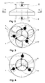
- FIG. 1 drives a wind-driven fan 1 at the end of a discharge pipe 2 a vertical central shaft 3, which is centrally mounted in a draw tube 2 with circular cross-section.
- a horizontal pin 4 is fixed to the shaft 3 and is driven by the fan 1 thereof.
- a circular flap 5 is rotatably mounted on the pin 4 and provided on the opposite sides with weights 6 . The flap 5 is urged by a return spring 7 in the open position.
- the flap 5 which has a regulating and locking function, rotates together with the fan 1 about the axis of rotation of the fan 1.
- the force acting against the spring force centrifugal force of the weights 6 causes change in position of the flap 5. This causes it to close, open and Controlling the volume flow through the pipe 2. This also works when the air in the pipe 2 swirls and whose revolutions are not significantly different from the revolutions of the fan 1 .
- the flap 5 can also react by means of a thermal regulator to temperature changes, which can change the initial position or bias of the force acting against the centrifugal force of the weights 6 return spring 7 .
- the control element is formed by segments 8 which are rotatably mounted on pins 10 .
- the to the Drive shaft 3 parallel pins 10 are attached to the circumference of a structure 9 , which is connected by three spokes to the drive shaft 3 .
- the segments 8 are provided with return springs 7 , which hold them in an open position. Against the effect of the return spring 7, the centrifugal force of the rotating weights 6, which are attached to the segments 8 at a distance from axes of the pins 10 acts. When the rotations reach a certain value, the centrifugal force of the weights 6 exceeds the bias of the spring 7, and the segments 8 begin to rotate in the closed position.
Landscapes
- Engineering & Computer Science (AREA)
- General Engineering & Computer Science (AREA)
- Mechanical Engineering (AREA)
- Combustion & Propulsion (AREA)
- Chemical & Material Sciences (AREA)
- Life Sciences & Earth Sciences (AREA)
- Fluid Mechanics (AREA)
- Physics & Mathematics (AREA)
- Environmental Sciences (AREA)
- Biodiversity & Conservation Biology (AREA)
- Animal Husbandry (AREA)
- Zoology (AREA)
- Air-Flow Control Members (AREA)
Abstract
Description
- Die Erfindung betrifft einen Volumenstromregler für fluide Medien, insbesondere für die Luft und andere Gase, die durch einen Kanal mit Kreisquerschnitt strömen. Die Einrichtung kann beispielsweise bei der Leistungsregelung von Dachentlüftung an Wohn-, Produktions-, Wirtschafts- und Lagergebäuden Verwendung finden, wo sie mit einem windgetriebenen Dachventilator kooperiert.
- Die Auftriebslüftung von Gebäuden wird durch windgetriebene Ventilatoren verstärkt, die am Ende der Abzugsrohren, in der Regel auf dem Dach, angebracht sind. Bekannt sind z.B. Dachventilatoren Hurricane, Lomaco oder Edmonds. Der Luftdurchfluss wird bei der gegenwärtigen Dachentlüftung meistens nicht geregelt. In einzelnen Fällen werden gängige lufttechnische, hand- oder motorgetriebene Klappen benutzt, oder die Umdrehungen des Ventilators werden durch einen elektronischen Regler in gewünschten Grenzen gehalten.
- Aus der
US 6402609 ist ein Dämpfer einer auf dem Dach eines Gebäudes angebrachten Windturbine bekannt, der durch eine Klappe gebildet ist, die in einem unter der Windturbine positionierten Rohr gelagert ist und durch einen Bowdenzug ferngesteuert wird. - In der
US 5183435 ist ein windgetriebener Dachventilator beschrieben, in dessen Zuführrohr mit Kreisquerschnitt eine radförmige Klappe an einer waagerechten Welle befestigt ist, die an beiden Enden in den Rohrwänden gelagert ist. Die Klappe wird durch eine außerhalb des Rohrs befindliche Kurbel bedient. - Die beiden angeführten Lösungen haben zum Nachteil, dass sie keine Selbstregelungsfähigkeit aufweisen.
- Bei Windstille dreht sich der windgetriebene Dachventilator nicht, und der Durchfluss der abgesaugten Luft nähert sich Null. Das ist aber unerwünscht, besonders bei hohen Temperaturen während der Sommermonate. Der Dachventilator kann dann durch einen Elektromotor zum Drehen gebracht werden, oder gegebenenfalls mit einem angetriebenen Lüfter ergänzt werden.
- Bei starkem Wind hat der Dachventilator dagegen eine hohe Drehzahl, so dass das Volumen der abgesaugten Luft tausende Kubikmeter pro Stunde erreichen kann. So eine Leistung ist während der Wintermonate unerwünscht, weil die in der abgeführten Luft enthaltene Wärme für das belüftete Bauwerk große Wärmeverluste bedeutet. Hier ist deswegen eine Durchflussregelung sehr wichtig.
- Der Erfindung liegt die Aufgabe zu Grunde, eine einfache Vorrichtung zur Volumenstromregelung an die Hand zu geben, die den Durchfluss eines fluiden Mediums bei Überdrehzahl des Antriebsmotors selbsttätig begrenzt.
- Erfindungsgemäß wird diese Aufgabe durch einen Volumenstromregler für fluide Medien gelöst, die durch einen Kanal mit Kreisquerschnitt strömen, der in einen windgetriebenen Ventilator mündet und in dem ein flaches bewegliches Element als Stellwerk funktioniert. Der Volumenregler ist durch eine, zentral in dem Kanal gelagerte und von dem Ventilator getriebene Antriebswelle gebildet, an der zumindest ein von der Antriebswelle getriebenes, federbelastetes flaches um einen Zapfen drehbar gelagertes Regelungselement angebracht ist, das in einem Abstand von der Zapfenachse mit einem Gewicht versehen ist.
- Das Regelungselement kann als eine an einem senkrecht zu der Antriebswelle positionierten Zapfen drehbar gelagerte rundförmige Klappe gebildet sein, die mit einer Rückfeder versehen ist.
- Das Regelungselement kann auch als eine Zusammensetzung federbelasteter Segmente gebildet sein, die an Zapfen drehbar gelagert sind, die an dem Umkreis eines von der Antriebswelle getriebenen Tragwerks parallel zu der Antriebswelle befestigt sind.
- Weitere Einzelheiten der Erfindung werden anhand der in der Zeichnung dargestellten Ausführungsbeispiele näher erläutert.
- Es zeigen:
- Fig. 1
- schematische Darstellung einer Ausführung eines erfindungsgemäßen Volumenstromreglers in Form einer Regelungsklappe, die von einer Welle eines windgetriebenen Dachventilators getrieben ist,
- Fig. 2
- bis 4 eine Ausführung eines Volumenstromreglers in Form eines sich drehenden Drosselventils mit drehbaren Segmenten, u. z.
- Fig. 2
- eine Seitenansicht der Verkleidung des Volumenreglers,
- Fig. 3
- der Volumenregler nach
Fig. 2 im Schnitt A-A mit geöffneten Segmenten bei niedrigen Umdrehungen und - Fig. 4
- mit geschlossenen Segmenten bei hohen Umdrehungen.
- In der Ausführung nach
Fig. 1 treibt ein windgetriebener Ventilator 1 am Ende eines Abzugsrohrs 2 eine senkrechte zentrale Welle 3, die in einem Abzugsrohr 2 mit Kreisquerschnitt zentral gelagert ist. Ein waagerechter Zapfen 4 ist an der Welle 3 befestigt und wird mittels deren vom Ventilator 1 getrieben. Eine kreisförmige Klappe 5 ist an dem Zapfen 4 drehbar gelagert und an den gegengesetzten Seiten mit Gewichten 6 versehen. Die Klappe 5 ist durch eine Rückfeder 7 in die geöffnete Lage gedrängt. - Die Klappe 5, die eine Regelungs- und Einsperrfunktion hat, dreht sich zusammen mit dem Ventilator 1 um die Drehachse des Ventilators 1. Die gegen die Federkraft wirkende Fliehkraft der Gewichte 6 bewirkt Lageänderung der Klappe 5. Dadurch kommt es zum Schließen, Öffnen und zur Regelung des Volumenstroms durch das Rohr 2. Das funktioniert auch, wenn die Luft in dem Rohr 2 wirbelt und deren Umdrehungen sich von den Umdrehungen des Ventilators 1 nicht wesentlich unterscheiden. Die Klappe 5 kann darüber hinaus mittels eines thermischen Reglers auf Temperaturänderungen reagieren, der deren Ausgangsstellung oder Vorspannung der gegen die Fliehkraft der Gewichte 6 wirkenden Rückfeder 7 umstellen kann.
- In der Ausführung des Volumenreglers nach
Fig. 2 bis 4 ist das Regelungselement durch Segmente 8 gebildet, die an Zapfen 10 drehbar gelagert sind. Die zu der Antriebswelle 3 parallelen Zapfen 10 sind am Umfang eines Tragwerks 9 befestigt, das durch drei Speichen mit der Antriebswelle 3 verbunden ist. Die Segmente 8 sind mit Rückfedern 7 versehen, die sie in einer offenen Lage halten. Gegen den Effekt der Rückfeder 7 wirkt die Fliehkraft der sich drehenden Gewichte 6, die an den Segmenten 8 mit einem Abstand von Achsen der Zapfen 10 befestigt sind. Wenn die Drehungen einen gewissen Wert erreichen, übersteigt die Fliehkraft der Gewichte 6 die Vorspannung der Feder 7, und die Segmente 8 beginnen, sich in die geschlossene Lage zu drehen. - Die Geschwindigkeit des Windes, der die Dachventilatoren antreibt, ist ungefähr proportional zu dem Volumen der abgesaugten Luft in dem Anschlussstutzen des windgetriebenen Dachventilators. Im Winter, bei Temperaturen um - 20°C und bei starkem Wind strömen ganz enorme Mengen der Wärmeenergie aus den Steigleitungen der perfekt wärmeisolierten mehrstöckigen Wohngebäude. Diese Wärme muss in die Gebäude wieder zurückgeliefert werden. Eine massenhafte Einführung der erfindungsgemäßen Regelungseinrichtung könnte enorme Wärmeersparnisse mit sich bringen und einen Beitrag zum Schutz der Umwelt leisten.
Claims (3)
- Ein Volumenstromregler für fluide Medien, die durch einen Kanal mit Kreisquerschnitt strömen, der in einen windgetriebenen Ventilator mündet und in dem ein flaches bewegliches Element als Stellwerk funktioniert, dadurch gekennzeichnet, dass er durch eine, zentral in dem Kanal (2) gelagerte und von dem Ventilator (1) getriebene Antriebswelle (3) gebildet ist, an der zumindest ein von der Antriebswelle (3) getriebenes, federbelastetes, flaches, um einen Zapfen (4, 10) drehbar gelagertes Regelungselement angebracht ist, das in einem Abstand von der Zapfenachse mit einem Gewicht (6) versehen ist.
- Der Volumenstromregler nach Anspruch 1, dadurch gekennzeichnet, dass das Regelungselement als eine an einem senkrecht zu der Antriebswelle (3) positionierten Zapfen (4) drehbar gelagerte rundförmige Klappe (5) gebildet ist, die mit einer Rückfeder (7) versehen ist.
- Der Volumenstromregler nach Anspruch 1, dadurch gekennzeichnet, dass das Regelungselement als eine Zusammensetzung federbelasteter Segmente (8) gebildet ist, die an Zapfen (10) drehbar gelagert sind, die an dem Umkreis eines von der Antriebswelle (3) getriebenen Tragwerks (9) parallel zu der Antriebswelle (3) befestigt sind.
Priority Applications (1)
| Application Number | Priority Date | Filing Date | Title |
|---|---|---|---|
| EP15002249.9A EP3124886B1 (de) | 2015-07-29 | 2015-07-29 | Volumenstromregler |
Applications Claiming Priority (1)
| Application Number | Priority Date | Filing Date | Title |
|---|---|---|---|
| EP15002249.9A EP3124886B1 (de) | 2015-07-29 | 2015-07-29 | Volumenstromregler |
Publications (2)
| Publication Number | Publication Date |
|---|---|
| EP3124886A1 true EP3124886A1 (de) | 2017-02-01 |
| EP3124886B1 EP3124886B1 (de) | 2018-04-18 |
Family
ID=57589816
Family Applications (1)
| Application Number | Title | Priority Date | Filing Date |
|---|---|---|---|
| EP15002249.9A Not-in-force EP3124886B1 (de) | 2015-07-29 | 2015-07-29 | Volumenstromregler |
Country Status (1)
| Country | Link |
|---|---|
| EP (1) | EP3124886B1 (de) |
Cited By (1)
| Publication number | Priority date | Publication date | Assignee | Title |
|---|---|---|---|---|
| EP3406986A1 (de) | 2017-05-22 | 2018-11-28 | TROX HESCO Schweiz AG | Volumenstromregler; lüftungsbox mit volumenstromregler |
Citations (3)
| Publication number | Priority date | Publication date | Assignee | Title |
|---|---|---|---|---|
| US4697736A (en) * | 1985-01-07 | 1987-10-06 | Leonard W. Suroff | Automatic damper assembly |
| US5183435A (en) | 1992-01-13 | 1993-02-02 | Galvez Bennie R | Seasonal attic turbine ventilator |
| US6402609B1 (en) | 2001-07-31 | 2002-06-11 | Neil Mangia | Seal vent |
-
2015
- 2015-07-29 EP EP15002249.9A patent/EP3124886B1/de not_active Not-in-force
Patent Citations (3)
| Publication number | Priority date | Publication date | Assignee | Title |
|---|---|---|---|---|
| US4697736A (en) * | 1985-01-07 | 1987-10-06 | Leonard W. Suroff | Automatic damper assembly |
| US5183435A (en) | 1992-01-13 | 1993-02-02 | Galvez Bennie R | Seasonal attic turbine ventilator |
| US6402609B1 (en) | 2001-07-31 | 2002-06-11 | Neil Mangia | Seal vent |
Cited By (1)
| Publication number | Priority date | Publication date | Assignee | Title |
|---|---|---|---|---|
| EP3406986A1 (de) | 2017-05-22 | 2018-11-28 | TROX HESCO Schweiz AG | Volumenstromregler; lüftungsbox mit volumenstromregler |
Also Published As
| Publication number | Publication date |
|---|---|
| EP3124886B1 (de) | 2018-04-18 |
Similar Documents
| Publication | Publication Date | Title |
|---|---|---|
| US8564154B2 (en) | Wind turbines with diffusers for the buildings or structures | |
| EP2798205B1 (de) | Strömungsmaschine | |
| US20110028080A1 (en) | Back draft damper | |
| CN205445656U (zh) | 百叶窗式风门 | |
| DE202013011686U1 (de) | Kombinierte Windanlage | |
| EP3124886B1 (de) | Volumenstromregler | |
| EP2462343B1 (de) | Windrad | |
| DE3028606A1 (de) | Zum einbau in rohrleitungen, kanaele oder kanalaehnliche gehaeuse bzw. in lueftungs- und klimageraete bestimmte ventilatoreinheit | |
| WO2016016777A1 (en) | Ventilation system and components thereof | |
| EP2236816A2 (de) | Kleinwindkraftanlage | |
| DE112017004377T5 (de) | Windturbinenanlage | |
| CN206452953U (zh) | 改进型畜禽圈舍屋顶用风帽 | |
| DE19739921A1 (de) | Windrad mit mittig nach oben offenen Windkasten | |
| DE102012008617B4 (de) | Verstellbarer Windflügel, insbesondere für Windkraftanlagen und deren Anordnung an Windkraftanlagen | |
| CN209180378U (zh) | 手动调节风阀 | |
| WO2021032255A1 (de) | Verfahren zur quantitativen bestimmung einer aktuellen betriebszustandsabhängigen grösse eines ventilators, insbesondere einer druckänderung oder druckerhöhung, und ventilator | |
| CN205554562U (zh) | 自适应抗突风弯折翼 | |
| DE19644917A1 (de) | Windenergiekonverter mit Sturmschutz | |
| DE202012002160U1 (de) | Anordnung von Windkraftmaschinen (WKM) in Luftkanälen, die im Dach eines Gebäudes gelagert sind | |
| RU2439442C1 (ru) | Система вентиляции воздуха в помещении | |
| CN109799060B (zh) | 一种带有调流段的直流吸式阵风风洞 | |
| CH702753B1 (de) | Doppelter Darrieus-Rotor. | |
| EP1577546A2 (de) | Windkraftanlage zur Umwandlung von Windenergie in andere Energieformen | |
| DE212008000104U1 (de) | Wind-Energieanlage | |
| CN109340146A (zh) | 廊风能自动换气扇 |
Legal Events
| Date | Code | Title | Description |
|---|---|---|---|
| PUAI | Public reference made under article 153(3) epc to a published international application that has entered the european phase |
Free format text: ORIGINAL CODE: 0009012 |
|
| AK | Designated contracting states |
Kind code of ref document: A1 Designated state(s): AL AT BE BG CH CY CZ DE DK EE ES FI FR GB GR HR HU IE IS IT LI LT LU LV MC MK MT NL NO PL PT RO RS SE SI SK SM TR |
|
| AX | Request for extension of the european patent |
Extension state: BA ME |
|
| 17P | Request for examination filed |
Effective date: 20170511 |
|
| RBV | Designated contracting states (corrected) |
Designated state(s): AL AT BE BG CH CY CZ DE DK EE ES FI FR GB GR HR HU IE IS IT LI LT LU LV MC MK MT NL NO PL PT RO RS SE SI SK SM TR |
|
| GRAP | Despatch of communication of intention to grant a patent |
Free format text: ORIGINAL CODE: EPIDOSNIGR1 |
|
| REG | Reference to a national code |
Ref country code: DE Ref legal event code: R079 Ref document number: 502015003875 Country of ref document: DE Free format text: PREVIOUS MAIN CLASS: F24F0013140000 Ipc: F24F0011740000 |
|
| INTG | Intention to grant announced |
Effective date: 20180119 |
|
| GRAS | Grant fee paid |
Free format text: ORIGINAL CODE: EPIDOSNIGR3 |
|
| RIC1 | Information provided on ipc code assigned before grant |
Ipc: F24F 11/74 20180101AFI20180208BHEP |
|
| GRAA | (expected) grant |
Free format text: ORIGINAL CODE: 0009210 |
|
| AK | Designated contracting states |
Kind code of ref document: B1 Designated state(s): AL AT BE BG CH CY CZ DE DK EE ES FI FR GB GR HR HU IE IS IT LI LT LU LV MC MK MT NL NO PL PT RO RS SE SI SK SM TR |
|
| REG | Reference to a national code |
Ref country code: GB Ref legal event code: FG4D Free format text: NOT ENGLISH |
|
| REG | Reference to a national code |
Ref country code: CH Ref legal event code: EP |
|
| REG | Reference to a national code |
Ref country code: DE Ref legal event code: R096 Ref document number: 502015003875 Country of ref document: DE |
|
| REG | Reference to a national code |
Ref country code: AT Ref legal event code: REF Ref document number: 990922 Country of ref document: AT Kind code of ref document: T Effective date: 20180515 |
|
| REG | Reference to a national code |
Ref country code: IE Ref legal event code: FG4D Free format text: LANGUAGE OF EP DOCUMENT: GERMAN |
|
| REG | Reference to a national code |
Ref country code: NL Ref legal event code: MP Effective date: 20180418 |
|
| REG | Reference to a national code |
Ref country code: LT Ref legal event code: MG4D |
|
| PG25 | Lapsed in a contracting state [announced via postgrant information from national office to epo] |
Ref country code: NL Free format text: LAPSE BECAUSE OF FAILURE TO SUBMIT A TRANSLATION OF THE DESCRIPTION OR TO PAY THE FEE WITHIN THE PRESCRIBED TIME-LIMIT Effective date: 20180418 |
|
| PG25 | Lapsed in a contracting state [announced via postgrant information from national office to epo] |
Ref country code: FI Free format text: LAPSE BECAUSE OF FAILURE TO SUBMIT A TRANSLATION OF THE DESCRIPTION OR TO PAY THE FEE WITHIN THE PRESCRIBED TIME-LIMIT Effective date: 20180418 Ref country code: NO Free format text: LAPSE BECAUSE OF FAILURE TO SUBMIT A TRANSLATION OF THE DESCRIPTION OR TO PAY THE FEE WITHIN THE PRESCRIBED TIME-LIMIT Effective date: 20180718 Ref country code: LT Free format text: LAPSE BECAUSE OF FAILURE TO SUBMIT A TRANSLATION OF THE DESCRIPTION OR TO PAY THE FEE WITHIN THE PRESCRIBED TIME-LIMIT Effective date: 20180418 Ref country code: PL Free format text: LAPSE BECAUSE OF FAILURE TO SUBMIT A TRANSLATION OF THE DESCRIPTION OR TO PAY THE FEE WITHIN THE PRESCRIBED TIME-LIMIT Effective date: 20180418 Ref country code: ES Free format text: LAPSE BECAUSE OF FAILURE TO SUBMIT A TRANSLATION OF THE DESCRIPTION OR TO PAY THE FEE WITHIN THE PRESCRIBED TIME-LIMIT Effective date: 20180418 Ref country code: SE Free format text: LAPSE BECAUSE OF FAILURE TO SUBMIT A TRANSLATION OF THE DESCRIPTION OR TO PAY THE FEE WITHIN THE PRESCRIBED TIME-LIMIT Effective date: 20180418 Ref country code: AL Free format text: LAPSE BECAUSE OF FAILURE TO SUBMIT A TRANSLATION OF THE DESCRIPTION OR TO PAY THE FEE WITHIN THE PRESCRIBED TIME-LIMIT Effective date: 20180418 Ref country code: BG Free format text: LAPSE BECAUSE OF FAILURE TO SUBMIT A TRANSLATION OF THE DESCRIPTION OR TO PAY THE FEE WITHIN THE PRESCRIBED TIME-LIMIT Effective date: 20180718 |
|
| PG25 | Lapsed in a contracting state [announced via postgrant information from national office to epo] |
Ref country code: LV Free format text: LAPSE BECAUSE OF FAILURE TO SUBMIT A TRANSLATION OF THE DESCRIPTION OR TO PAY THE FEE WITHIN THE PRESCRIBED TIME-LIMIT Effective date: 20180418 Ref country code: RS Free format text: LAPSE BECAUSE OF FAILURE TO SUBMIT A TRANSLATION OF THE DESCRIPTION OR TO PAY THE FEE WITHIN THE PRESCRIBED TIME-LIMIT Effective date: 20180418 Ref country code: GR Free format text: LAPSE BECAUSE OF FAILURE TO SUBMIT A TRANSLATION OF THE DESCRIPTION OR TO PAY THE FEE WITHIN THE PRESCRIBED TIME-LIMIT Effective date: 20180719 Ref country code: HR Free format text: LAPSE BECAUSE OF FAILURE TO SUBMIT A TRANSLATION OF THE DESCRIPTION OR TO PAY THE FEE WITHIN THE PRESCRIBED TIME-LIMIT Effective date: 20180418 |
|
| PG25 | Lapsed in a contracting state [announced via postgrant information from national office to epo] |
Ref country code: PT Free format text: LAPSE BECAUSE OF FAILURE TO SUBMIT A TRANSLATION OF THE DESCRIPTION OR TO PAY THE FEE WITHIN THE PRESCRIBED TIME-LIMIT Effective date: 20180820 |
|
| REG | Reference to a national code |
Ref country code: DE Ref legal event code: R097 Ref document number: 502015003875 Country of ref document: DE |
|
| PG25 | Lapsed in a contracting state [announced via postgrant information from national office to epo] |
Ref country code: EE Free format text: LAPSE BECAUSE OF FAILURE TO SUBMIT A TRANSLATION OF THE DESCRIPTION OR TO PAY THE FEE WITHIN THE PRESCRIBED TIME-LIMIT Effective date: 20180418 Ref country code: DK Free format text: LAPSE BECAUSE OF FAILURE TO SUBMIT A TRANSLATION OF THE DESCRIPTION OR TO PAY THE FEE WITHIN THE PRESCRIBED TIME-LIMIT Effective date: 20180418 Ref country code: SK Free format text: LAPSE BECAUSE OF FAILURE TO SUBMIT A TRANSLATION OF THE DESCRIPTION OR TO PAY THE FEE WITHIN THE PRESCRIBED TIME-LIMIT Effective date: 20180418 Ref country code: RO Free format text: LAPSE BECAUSE OF FAILURE TO SUBMIT A TRANSLATION OF THE DESCRIPTION OR TO PAY THE FEE WITHIN THE PRESCRIBED TIME-LIMIT Effective date: 20180418 Ref country code: CZ Free format text: LAPSE BECAUSE OF FAILURE TO SUBMIT A TRANSLATION OF THE DESCRIPTION OR TO PAY THE FEE WITHIN THE PRESCRIBED TIME-LIMIT Effective date: 20180418 |
|
| REG | Reference to a national code |
Ref country code: DE Ref legal event code: R119 Ref document number: 502015003875 Country of ref document: DE |
|
| PLBE | No opposition filed within time limit |
Free format text: ORIGINAL CODE: 0009261 |
|
| STAA | Information on the status of an ep patent application or granted ep patent |
Free format text: STATUS: NO OPPOSITION FILED WITHIN TIME LIMIT |
|
| PG25 | Lapsed in a contracting state [announced via postgrant information from national office to epo] |
Ref country code: IT Free format text: LAPSE BECAUSE OF FAILURE TO SUBMIT A TRANSLATION OF THE DESCRIPTION OR TO PAY THE FEE WITHIN THE PRESCRIBED TIME-LIMIT Effective date: 20180418 Ref country code: SM Free format text: LAPSE BECAUSE OF FAILURE TO SUBMIT A TRANSLATION OF THE DESCRIPTION OR TO PAY THE FEE WITHIN THE PRESCRIBED TIME-LIMIT Effective date: 20180418 |
|
| REG | Reference to a national code |
Ref country code: CH Ref legal event code: PL |
|
| 26N | No opposition filed |
Effective date: 20190121 |
|
| PG25 | Lapsed in a contracting state [announced via postgrant information from national office to epo] |
Ref country code: MC Free format text: LAPSE BECAUSE OF FAILURE TO SUBMIT A TRANSLATION OF THE DESCRIPTION OR TO PAY THE FEE WITHIN THE PRESCRIBED TIME-LIMIT Effective date: 20180418 Ref country code: LU Free format text: LAPSE BECAUSE OF NON-PAYMENT OF DUE FEES Effective date: 20180729 |
|
| REG | Reference to a national code |
Ref country code: BE Ref legal event code: MM Effective date: 20180731 |
|
| PG25 | Lapsed in a contracting state [announced via postgrant information from national office to epo] |
Ref country code: FR Free format text: LAPSE BECAUSE OF NON-PAYMENT OF DUE FEES Effective date: 20180731 Ref country code: LI Free format text: LAPSE BECAUSE OF NON-PAYMENT OF DUE FEES Effective date: 20180731 Ref country code: CH Free format text: LAPSE BECAUSE OF NON-PAYMENT OF DUE FEES Effective date: 20180731 Ref country code: DE Free format text: LAPSE BECAUSE OF NON-PAYMENT OF DUE FEES Effective date: 20190201 |
|
| REG | Reference to a national code |
Ref country code: IE Ref legal event code: MM4A |
|
| PG25 | Lapsed in a contracting state [announced via postgrant information from national office to epo] |
Ref country code: BE Free format text: LAPSE BECAUSE OF NON-PAYMENT OF DUE FEES Effective date: 20180731 Ref country code: SI Free format text: LAPSE BECAUSE OF FAILURE TO SUBMIT A TRANSLATION OF THE DESCRIPTION OR TO PAY THE FEE WITHIN THE PRESCRIBED TIME-LIMIT Effective date: 20180418 |
|
| PG25 | Lapsed in a contracting state [announced via postgrant information from national office to epo] |
Ref country code: IE Free format text: LAPSE BECAUSE OF NON-PAYMENT OF DUE FEES Effective date: 20180729 |
|
| PG25 | Lapsed in a contracting state [announced via postgrant information from national office to epo] |
Ref country code: MT Free format text: LAPSE BECAUSE OF FAILURE TO SUBMIT A TRANSLATION OF THE DESCRIPTION OR TO PAY THE FEE WITHIN THE PRESCRIBED TIME-LIMIT Effective date: 20180418 |
|
| GBPC | Gb: european patent ceased through non-payment of renewal fee |
Effective date: 20190729 |
|
| PG25 | Lapsed in a contracting state [announced via postgrant information from national office to epo] |
Ref country code: TR Free format text: LAPSE BECAUSE OF FAILURE TO SUBMIT A TRANSLATION OF THE DESCRIPTION OR TO PAY THE FEE WITHIN THE PRESCRIBED TIME-LIMIT Effective date: 20180418 |
|
| PG25 | Lapsed in a contracting state [announced via postgrant information from national office to epo] |
Ref country code: GB Free format text: LAPSE BECAUSE OF NON-PAYMENT OF DUE FEES Effective date: 20190729 |
|
| PG25 | Lapsed in a contracting state [announced via postgrant information from national office to epo] |
Ref country code: MK Free format text: LAPSE BECAUSE OF NON-PAYMENT OF DUE FEES Effective date: 20180418 Ref country code: CY Free format text: LAPSE BECAUSE OF FAILURE TO SUBMIT A TRANSLATION OF THE DESCRIPTION OR TO PAY THE FEE WITHIN THE PRESCRIBED TIME-LIMIT Effective date: 20180418 Ref country code: HU Free format text: LAPSE BECAUSE OF FAILURE TO SUBMIT A TRANSLATION OF THE DESCRIPTION OR TO PAY THE FEE WITHIN THE PRESCRIBED TIME-LIMIT; INVALID AB INITIO Effective date: 20150729 |
|
| PG25 | Lapsed in a contracting state [announced via postgrant information from national office to epo] |
Ref country code: IS Free format text: LAPSE BECAUSE OF FAILURE TO SUBMIT A TRANSLATION OF THE DESCRIPTION OR TO PAY THE FEE WITHIN THE PRESCRIBED TIME-LIMIT Effective date: 20180818 |
|
| PGFP | Annual fee paid to national office [announced via postgrant information from national office to epo] |
Ref country code: AT Payment date: 20200602 Year of fee payment: 6 |
|
| REG | Reference to a national code |
Ref country code: AT Ref legal event code: MM01 Ref document number: 990922 Country of ref document: AT Kind code of ref document: T Effective date: 20210729 |
|
| PG25 | Lapsed in a contracting state [announced via postgrant information from national office to epo] |
Ref country code: AT Free format text: LAPSE BECAUSE OF NON-PAYMENT OF DUE FEES Effective date: 20210729 |