EP3124755A1 - Generator device - Google Patents
Generator device Download PDFInfo
- Publication number
- EP3124755A1 EP3124755A1 EP15767732.9A EP15767732A EP3124755A1 EP 3124755 A1 EP3124755 A1 EP 3124755A1 EP 15767732 A EP15767732 A EP 15767732A EP 3124755 A1 EP3124755 A1 EP 3124755A1
- Authority
- EP
- European Patent Office
- Prior art keywords
- working medium
- cooling
- heater
- medium
- flow passage
- Prior art date
- Legal status (The legal status is an assumption and is not a legal conclusion. Google has not performed a legal analysis and makes no representation as to the accuracy of the status listed.)
- Withdrawn
Links
- 238000001816 cooling Methods 0.000 claims abstract description 92
- 238000011144 upstream manufacturing Methods 0.000 claims description 6
- 238000009834 vaporization Methods 0.000 claims description 4
- 230000008016 vaporization Effects 0.000 claims description 4
- 238000001704 evaporation Methods 0.000 abstract 1
- 239000002826 coolant Substances 0.000 description 17
- 238000001514 detection method Methods 0.000 description 15
- 239000007788 liquid Substances 0.000 description 15
- XLYOFNOQVPJJNP-UHFFFAOYSA-N water Substances O XLYOFNOQVPJJNP-UHFFFAOYSA-N 0.000 description 15
- 238000012856 packing Methods 0.000 description 6
- 238000010586 diagram Methods 0.000 description 5
- 238000010248 power generation Methods 0.000 description 5
- 239000003779 heat-resistant material Substances 0.000 description 4
- 230000005856 abnormality Effects 0.000 description 2
- 239000000498 cooling water Substances 0.000 description 2
- 239000011810 insulating material Substances 0.000 description 2
- 238000009529 body temperature measurement Methods 0.000 description 1
- 238000009835 boiling Methods 0.000 description 1
- 238000010411 cooking Methods 0.000 description 1
- 239000003507 refrigerant Substances 0.000 description 1
Images



Classifications
-
- F—MECHANICAL ENGINEERING; LIGHTING; HEATING; WEAPONS; BLASTING
- F01—MACHINES OR ENGINES IN GENERAL; ENGINE PLANTS IN GENERAL; STEAM ENGINES
- F01K—STEAM ENGINE PLANTS; STEAM ACCUMULATORS; ENGINE PLANTS NOT OTHERWISE PROVIDED FOR; ENGINES USING SPECIAL WORKING FLUIDS OR CYCLES
- F01K13/00—General layout or general methods of operation of complete plants
- F01K13/02—Controlling, e.g. stopping or starting
-
- F—MECHANICAL ENGINEERING; LIGHTING; HEATING; WEAPONS; BLASTING
- F01—MACHINES OR ENGINES IN GENERAL; ENGINE PLANTS IN GENERAL; STEAM ENGINES
- F01K—STEAM ENGINE PLANTS; STEAM ACCUMULATORS; ENGINE PLANTS NOT OTHERWISE PROVIDED FOR; ENGINES USING SPECIAL WORKING FLUIDS OR CYCLES
- F01K9/00—Plants characterised by condensers arranged or modified to co-operate with the engines
- F01K9/003—Plants characterised by condensers arranged or modified to co-operate with the engines condenser cooling circuits
Definitions
- the present invention relates to a generator device.
- Patent Document 1 there is a known binary generator device in which a power generator is driven by an expander provided in a circulation pipe through which a working medium is circulated.
- a power generator is driven by an expander provided in a circulation pipe through which a working medium is circulated.
- Fig. 7 in this binary generator device disclosed in Patent Document 1, an evaporator 71, an expander 72, a condenser 73, and a circulation pump 74 are connected to a circulation pipe 75 in this order.
- the evaporator 71 evaporates a working medium with discharged hot water discharged from factories or hot water from hot springs as a heat source medium.
- a temperature measurement means 76 is provided on the outlet side of the evaporator 71 in a flow passage through which the heat source medium flows.
- the rotation number of the circulation pump 74 is adjusted. That is, when a temperature of the hot water on the outlet side of the evaporator 71 becomes a higher temperature than a target value, the temperature of the hot water on the outlet side is lowered by increasing the rotation number of the circulation pump 74.
- Patent Document 1 JP 2013-181398 A
- An object of the present invention is to be able to suppress an increase in a temperature of a working medium on the outlet side of a heater in a generator device.
- a generator device includes an expander that expands a gaseous working medium, a condenser that condenses the working medium expanded in the expander, a pump that pressurizes the working medium condensed in the condenser, a heater that evaporates at least part of the working medium pressurized in the pump with heat of a heat source medium, and a cooling means that cools the working medium in an overheat state where the working medium has a preliminarily fixed temperature or higher on the downstream side of the heater.
- a power generator 16 is connected to the expander 14. By expanding the gaseous working medium in the expander 14, force to drive the power generator 16 can be taken out.
- the circulation pump 8 is provided on the downstream side of the condenser 6 (between the heater 10 and the condenser 6) in the circulation flow passage 4, to circulate the working medium in the circulation flow passage 4.
- the circulation pump 8 pressurizes the liquid working medium condensed in the condenser 6 up to predetermined pressure and feeds the working medium to the heater 10.
- a centrifugal pump including an impeller as a rotor, a gear pump whose rotor includes a pair of gears, and the like are used.
- the heater 10 is provided on the downstream side of the circulation pump 8 (between the circulation pump 8 and the expander 14) in the circulation flow passage 4.
- the heater 10 has a working medium flow passage 10a through which the working medium flows, and a heat source medium flow passage 10b through which a heat source medium flows.
- the heat source medium flow passage 10b is connected to a heat source medium circuit 62. Through this heat source medium flow passage 10b, a heat source medium supplied from an external heat source flows.
- the working medium flowing through the working medium flow passage 10a is evaporated by heat exchange with the heat source medium flowing through the heat source medium flow passage 10b.
- the heat source medium includes, for example, hot water and water vapor.
- shutoff valve 21 is provided between the heater 10 and the expander 14.
- the shutoff valve 21 is usually opened but closed at the time of stopping the expander 14 and the like, for example at the time of abnormality of the expander 14.
- the bypass means 23 has a bypass passage 23a bypassing the expander 14, and an on-off valve 23b provided in the bypass passage 23a.
- the on-off valve 23b is usually closed but opened at the time of stopping the expander 14 and the like, for example at the time of rotation abnormality of the expander 14. By opening the on-off valve 23b, the working medium flowing out from the heater 10 is introduced into the condenser 6 without being introduced into the expander 14.
- the cooling means 25 is to cool the gaseous working medium evaporated in the heater 10 (that is, to draw sensible heat from the working medium), and has a cooling passage 25a, and a cooling valve (on-off valve) 25b provided in the cooling passage 25a.
- a one end part of the cooling passage 25a is connected to a part between the circulation pump 8 and the heater 10 in the circulation flow passage 4. Therefore, the liquid working medium flows into the cooling passage 25a.
- the other end part of the cooling passage 25a is connected to a part between the heater 10 and the expander 14 in the circulation flow passage 4. Therefore, the liquid working medium flowing through the cooling passage 25a is united with the gaseous working medium flowing out from the heater 10.
- the cooling passage 25a is formed by a pipe thinner than a pipe forming the circulation flow passage 4. Therefore, through the cooling passage 25a, the working medium flows at a sufficiently small flow rate in comparison to the working medium flowing through the circulation flow passage 4. It should be noted that a throttle or a capillary tube (not shown) may be alternatively provided in the cooling passage 25a.
- the cooling valve 25b is usually closed but opened when a command is received from a controller 30 to be described later.
- a temperature sensor 32 and a pressure sensor 34 are provided between a part to which a downstream end of the cooling passage 25a is connected and the expander 14.
- the temperature sensor 32 detects a temperature of the working medium flowing out from the heater 10 to be introduced into the shutoff valve 21 and the expander 14.
- the pressure sensor 34 detects pressure of the working medium flowing out from the heater 10 to be introduced into the shutoff valve 21 and the expander 14.
- the controller 30 that performs drive control of the circulation pump 8, and open/close control of the on-off valves 21, 23b, 25b is provided.
- Functions of the controller 30 include a pump control means 30a and a cooling control means 30b.
- the pump control means 30a is a means for controlling the rotation number of the circulation pump 8, and performs the drive control of the circulation pump 8 in such a manner that an overheat level of the working medium derived from detection values of the temperature sensor 32 and the pressure sensor 34 is held within a preliminarily set range.
- the cooling control means 30b is a means for controlling open/close of the cooling valve 25b, and executes the open/close control of the cooling valve 25b based on the temperature of the working medium flowing out from the heater 10. That is, the cooling control means 30b outputs a command for opening the cooling valve 25b in a case where the working medium on the downstream side of the heater 10 is judged to be in an overheat state from the detection values of the temperature sensor 32 and the pressure sensor 34, and when the detection value of the temperature sensor 32 is judged to be a preliminarily fixed temperature (reference temperature) or higher.
- reference temperature a temperature that does not damage a packing or the like (not shown) provided in a connection part of the shutoff valve 21 is set. That is, the temperature of the working medium at an outlet of the heater 10 is controlled in such a manner that the packing is not damaged by heat received from the working medium even in a case where the packing is not made of a heat-resistant material.
- the cooling control means 30b also executes the close control of the cooling valve 25b in such a manner that cooling is made within a range where the temperature of the working medium on the downstream side of the heater 10 is maintained to be a saturation temperature or higher. That is, in order to maintain the temperature of the working medium to be introduced into the expander 14 to be the saturation temperature or higher, the cooling control means 30b outputs a command for closing the cooling valve 25b when a preliminarily fixed closing condition is met.
- This closing condition includes, for example, the fact that the overheat level of the working medium obtained from the detection values of the temperature sensor 32 and the pressure sensor 34 is a predetermined temperature or higher. It should be noted that the temperature of the working medium at this time is a temperature lower than the above reference temperature.
- shutoff valve 21 is opened, whereas the on-off valve 23b of the bypass passage 23a and the cooling valve 25b are closed.
- the circulation pump 8 When the circulation pump 8 is driven, the liquid working medium fed out from the circulation pump 8 flows into the working medium flow passage 10a of the heater 10. This working medium is heated and evaporated by the heat source medium flowing through the heat source medium flow passage 10b. The working medium evaporated in the heater 10 is introduced into the expander 14. By introducing the working medium into the expander 14, the expander 14 is driven and rotated, and thereby the power generator 16 is driven to generate electric power. The working medium expanded from the expander 14 is discharged to the circulation flow passage 4. The gaseous working medium discharged from the expander 14 is introduced into the working medium flow passage 6a of the condenser 6. In the condenser 6, the working medium is cooled and condensed by the cooling medium flowing through the cooling medium flow passage 6b. This liquid working medium flows through the circulation flow passage 4 and is suctioned into the circulation pump 8. In the circulation flow passage 4, such circulation is repeated and the electric power is generated in the power generator 16.
- the rotation number of the circulation pump 8 is controlled in such a manner that the overheat level of the working medium on the downstream side of the heater 10 is held within a predetermined range. That is, as shown in Fig. 2 , the detection values P1, T1 of the pressure sensor 34 and the temperature sensor 32 are inputted to the controller 30 (Step ST1), and the pump control means 30a controls the circulation pump 8 based on the detections values P1, T1 in such a manner that the overheat level of the working medium is held within a preliminarily fixed range (Step ST2).
- the cooling control means 30b judges whether or not the detection value T1 of the temperature sensor 32 is a preliminarily set reference temperature (upper limit value) Tr or lower (Steps ST3, ST4).
- an overheat state indicates a state where the temperature detection value T1 is higher than the saturation temperature of the working medium with the pressure detection value P1.
- the cooling valve 25b is opened (Step ST5). Such a situation occurs for example in a case where an increase in the rotation number of the circulation pump 8 cannot deal with a radical increase in the temperature of the heat source medium to be introduced into the heater 10, or the like.
- the cooling passage 25a is formed by a thin pipe in comparison to the circulation flow passage 4, a flow of a large amount of the working medium through the cooling passage 25a is prevented. Therefore, an amount of the working medium to flow into the heater 10 through the circulation flow passage 4 is not reduced enough to influence an amount of the working medium caught in the heater 10, and the overheat level is hardly further increased.
- Step ST6 it is judged whether or not the overheat level SH calculated from the detection values T1, P1 of the temperature sensor 32 and the pressure sensor 34 is a reference overheat level (lower limit value) SHr or higher.
- the overheat level SH becomes lower than the reference overheat level SHr, the cooling valve 25b is closed (Step ST7). Thereby, the operation is returned to the normal operation in which the working medium emitted from the circulation pump 8 is introduced into the heater 10 without being split into the cooling passage 25a.
- the cooling means 25 cools the working medium in an overheat state where the temperature on the downstream side of the heater 10 is a preliminarily fixed value or higher. Therefore, the temperature of the working medium flowing out from the heater 10 to flow into the expander 14 can be suppressed. Thus, even in a case where the temperature of the heat source medium is radically increased, or the like, an increase in the temperature of the working medium can be effectively suppressed. Consequently, there is no need for making the packing or the like of a flange that exists in a route running from the heater 10 to the expander 14 of a heat-resistant material. There is also no need for a measure of making a class of an insulating material used in the power generator 16 higher, or the like.
- the cooling means 25 cools the working medium by uniting the working medium split from the downstream side of the pump and the upstream side of the heater 10 into the circulation flow passage 4. Therefore, a configuration as the generator device 1 can be suppressed from being complicated, and the working medium can be more effectively cooled.
- the working medium on the downstream side of the heater 10 is maintained to be the saturation temperature or higher.
- the liquid working medium can be prevented from being introduced into the expander 14. Therefore, power generation efficiency can be prevented from lowering.
- the working medium in an overheat state is cooled by utilizing vaporization heat of the working medium.
- the working medium can be more effectively cooled. That is, the working medium in an overheat state can be cooled with a tiny amount of the cooling medium.
- the working medium split from the downstream side of the circulation pump 8 is used as the cooling medium, an amount of the working medium fed from the circulation pump 8 to the heater 10 is only slightly reduced. Therefore, even when the working medium is split from the working medium emitted from the circulation pump 8, there is almost no influence.
- surplus vapor may be introduced from a steam system (not shown) provided in a vessel which is equipped with the engine.
- a steam system not shown
- the supercharged air of about 150°C or higher is introduced into the heater 10. Therefore, the working medium flowing through a working medium flow passage 10a of the heater 10 is heated until a temperature of the working medium becomes about 150°C.
- a cooling valve pressure reduction means
- the working medium in an overheat state flowing through a working medium flow passage 25d of the heat exchanger 25f can be cooled.
- the working medium may sometimes be insufficiently heated in the heater 10.
- the heat exchanger 25f can also function as a superheater that heats and brings the working medium into an overheat state.
- a cooling control means 30b performs control of constricting the cooling valve 25b (Step ST11). Thereby, the pressure of the heat medium is reduced, and the working medium is cooled in the heat exchanger 25f (sensible heat of the working medium is drawn).
- the present invention is not limited to the above first and second embodiments but can be variously modified or improved within a range not departing from the gist thereof.
- the working medium split from the circulation flow passage 4 is united with the working medium of the circulation flow passage 4 again on the downstream side of the heater 10, and heat exchange is performed directly with the working medium.
- heat exchange may be performed indirectly between the working medium split into the cooling passage 25a and the working medium of the circulation flow passage 4.
- the cooling means 25 has a cooling heat exchanger 25c arranged on the downstream side of the heater 10 in the circulation flow passage 4.
- a working medium flow passage 25d connected to the circulation flow passage 4 and a cooling flow passage 25e connected to the cooling passage 25a are provided.
- a one end part (upstream end part) of the cooling passage 25a is connected to a part between the circulation pump 8 and the heater 10 in the circulation flow passage 4.
- the other end part (downstream end part) of the cooling passage 25a is connected to a part between the expander 14 and the condenser 6 in the circulation flow passage 4. Since the downstream end part of the cooling passage 25a is placed on the suction side of the circulation pump 8 in the circulation flow passage 4, the working medium split into the cooling passage 25a easily flows.
- the liquid working medium split from the circulation flow passage 4 to the cooling passage 25a is gasified while cooling the working medium of the working medium flow passage 25d in an overheat state in the cooling heat exchanger 25c.
- the gasified working medium is returned from the cooling passage 25a to the upstream side of the condenser 6 in the circulation flow passage 4.
- a jacket covering part of a pipe part between the heater 10 and the expander 14 in the circulation flow passage 4 may be provided, and the working medium flowing out from the heater 10 may be indirectly cooled by letting the working medium or the cooling medium in the jacket.
- the cooling valve 25a may be a valve whose opening degree is adjustable.
- the cooling means cools the working medium in an overheat state where the temperature on the downstream side of the heater is a preliminarily fixed value or higher. Therefore, the temperature of the working medium flowing out from the heater to flow into the expander can be suppressed. Thus, even in a case where the temperature of the heat source medium is radically increased, or the like, the increase in the temperature of the working medium can be effectively suppressed. Consequently, there is no need for making the packing or the like of the flange that exists in the route running from the heater to the expander of a heat-resistant material. There is also no need for a measure of making a class of the insulating material used in the power generator higher, or the like.
- the cooling means may cool the above working medium in an overheat state with the working medium split from the downstream side of the pump and the upstream side of the heater. In this mode, the working medium in an overheat state is cooled with the working medium emitted from the pump.
- the configuration as the generator device can be suppressed from being complicated.
- the cooling means may cool the above working medium in an overheat state by uniting the working medium split from the downstream side of the pump with the working medium on the downstream side of the heater. In this mode, the working medium is cooled by uniting the working medium split from the downstream side of the pump with the working medium in an overheat state. Therefore, the working medium can be more effectively cooled.
- the cooling means may cool the working medium in an overheat state by utilizing vaporization heat.
- the working medium in an overheat state is cooled by utilizing vaporization heat.
- the working medium can be more effectively cooled. That is, the working medium in an overheat state can be cooled with a tiny amount of the cooling medium.
- the amount of the working medium fed from the pump to the heater is only slightly reduced. Therefore, even when the working medium is split from the working medium emitted from the pump, there is almost no influence.
- the cooling means may have the working medium flow passage and the cooling flow passage, and have the heat exchanger arranged on the downstream side of the heater, and the pressure reduction means provided in a heat medium circuit which is connected to the cooling flow passage.
- the pressure reduction means may reduce the pressure of the heat medium in such a manner that when the working medium is in an overheat state where the working medium has a preliminarily fixed temperature or higher, the working medium is cooled in the heat exchanger.
- the heat exchanger when the working medium is in an overheat state where the working medium has a preliminarily fixed temperature or higher, in the heat exchanger, the pressure of the working medium flowing through the working medium flow passage is reduced by the pressure reduction means of the heat medium circuit and the working medium is cooled with the heat medium flowing through the cooling flow passage. Meanwhile, in a case where the working medium is insufficiently heated in the heater, the working medium is heated with the heat medium in the heat exchanger. Therefore, the heat exchanger can cool the working medium in a case where the working medium is excessively heated, and also supplementarily heat the working medium in a case where the working medium is insufficiently heated.
- the increase in the temperature of the working medium on the outlet side of the heater can be suppressed in the generator device.
Landscapes
- Engineering & Computer Science (AREA)
- Chemical & Material Sciences (AREA)
- Combustion & Propulsion (AREA)
- Mechanical Engineering (AREA)
- General Engineering & Computer Science (AREA)
- Engine Equipment That Uses Special Cycles (AREA)
- Control Of Turbines (AREA)
Abstract
Description
- The present invention relates to a generator device.
- Conventionally, as disclosed in Patent Document 1 below, there is a known binary generator device in which a power generator is driven by an expander provided in a circulation pipe through which a working medium is circulated. As shown in
Fig. 7 , in this binary generator device disclosed in Patent Document 1, anevaporator 71, anexpander 72, acondenser 73, and acirculation pump 74 are connected to acirculation pipe 75 in this order. Theevaporator 71 evaporates a working medium with discharged hot water discharged from factories or hot water from hot springs as a heat source medium. On the outlet side of theevaporator 71 in a flow passage through which the heat source medium flows, a temperature measurement means 76 is provided. Based on a measured value of this means, the rotation number of thecirculation pump 74 is adjusted. That is, when a temperature of the hot water on the outlet side of theevaporator 71 becomes a higher temperature than a target value, the temperature of the hot water on the outlet side is lowered by increasing the rotation number of thecirculation pump 74. - In the above binary generator device disclosed in Patent Document 1, in a case where the temperature of the hot water serving as a heat source is increased, the temperature of the hot water flowing out from the
evaporator 71 is lowered by increasing the rotation number of thecirculation pump 74. Thereby, the temperature of the hot water flowing out from theevaporator 71 can be held within a predetermined range. However, in this binary generator device, there is still a problem that the device cannot deal with a case where the temperature of the hot water (heat source medium) is radically increased. That is, when the temperature of the hot water on the outlet side of theevaporator 71 is increased, adjustment is made to increase the rotation number of thecirculation pump 74. However, in a case where temperature of the hot water is radically increased, an increase in a flow rate of the working medium does not catch up, so that an overheat level of an outlet of the evaporator is temporarily increased. Therefore, there is a problem that a packing or the like of a flange that exists in a route running from theevaporator 71 to theexpander 72 has to be made of a heat-resistant material. - Patent Document 1:
JP 2013-181398 A - An object of the present invention is to be able to suppress an increase in a temperature of a working medium on the outlet side of a heater in a generator device.
- A generator device according to one aspect of the present invention includes an expander that expands a gaseous working medium, a condenser that condenses the working medium expanded in the expander, a pump that pressurizes the working medium condensed in the condenser, a heater that evaporates at least part of the working medium pressurized in the pump with heat of a heat source medium, and a cooling means that cools the working medium in an overheat state where the working medium has a preliminarily fixed temperature or higher on the downstream side of the heater.
-
- [
Fig.1] Fig. 1 is a diagram schematically showing a configuration of a generator device according to a first embodiment of the present invention. - [
Fig. 2] Fig. 2 is a chart for explaining control actions in the generator device according to the first embodiment. - [
Fig.3] Fig. 3 is a diagram schematically showing a configuration of a generator device according to a second embodiment of the present invention. - [
Fig. 4] Fig. 4 is a chart for explaining control actions in the generator device according to the second embodiment. - [
Fig.5] Fig. 5 is a diagram schematically showing a configuration of a generator device according to one of other embodiments of the present invention. - [
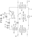
Fig. 6] Fig. 6 is a diagram schematically showing a configuration of a generator device according to one of other embodiments of the present invention. - [
Fig.7] Fig. 7 is a diagram schematically showing a configuration of a conventional binary generator device. - Hereinafter, modes for carrying out the present invention will be described in detail with reference to the drawings.
- A generator device 1 according to a first embodiment is a power generation system in which the Rankine cycle is utilized, and includes a condenser 6, a
circulation pump 8, aheater 10, and anexpander 14 as shown inFig. 1 . The condenser 6, thecirculation pump 8, theheater 10, and theexpander 14 are provided in acirculation flow passage 4 in this order. In the generator device 1 according to the present embodiment, a circulation circuit in which a working medium flows through theheater 10, theexpander 14, the condenser 6, and thecirculation pump 8 in order through thecirculation flow passage 4 is formed. A refrigerant having a lower boiling point than that of water is used as the working medium. - A
power generator 16 is connected to theexpander 14. By expanding the gaseous working medium in theexpander 14, force to drive thepower generator 16 can be taken out. - The condenser 6 is to condense and make the gaseous working medium discharged from the expander 14 a liquid working medium. The condenser 6 has a working
medium flow passage 6a through which the gaseous working medium flows, and a coolingmedium flow passage 6b through which a cooling medium such as cooking water flows. The coolingmedium flow passage 6b is connected to acooling circuit 61. Through the coolingmedium flow passage 6b, the cooling medium such as cooling water supplied from thiscooling circuit 61 flows. The working medium flowing through the workingmedium flow passage 6a is condensed by heat exchange with the cooling medium flowing through the coolingmedium flow passage 6b. - The
circulation pump 8 is provided on the downstream side of the condenser 6 (between theheater 10 and the condenser 6) in thecirculation flow passage 4, to circulate the working medium in thecirculation flow passage 4. Thecirculation pump 8 pressurizes the liquid working medium condensed in the condenser 6 up to predetermined pressure and feeds the working medium to theheater 10. As thecirculation pump 8, a centrifugal pump including an impeller as a rotor, a gear pump whose rotor includes a pair of gears, and the like are used. - The
heater 10 is provided on the downstream side of the circulation pump 8 (between thecirculation pump 8 and the expander 14) in thecirculation flow passage 4. Theheater 10 has a workingmedium flow passage 10a through which the working medium flows, and a heat sourcemedium flow passage 10b through which a heat source medium flows. The heat sourcemedium flow passage 10b is connected to a heatsource medium circuit 62. Through this heat sourcemedium flow passage 10b, a heat source medium supplied from an external heat source flows. The working medium flowing through the workingmedium flow passage 10a is evaporated by heat exchange with the heat source medium flowing through the heat sourcemedium flow passage 10b. The heat source medium includes, for example, hot water and water vapor. - In the
circulation flow passage 4, a shutoff valve (on-off valve) 21 is provided between theheater 10 and theexpander 14. Theshutoff valve 21 is usually opened but closed at the time of stopping theexpander 14 and the like, for example at the time of abnormality of theexpander 14. - In the
circulation flow passage 4, a bypass means 23 and a cooling means 25 are provided. The bypass means 23 has abypass passage 23a bypassing theexpander 14, and an on-offvalve 23b provided in thebypass passage 23a. The on-offvalve 23b is usually closed but opened at the time of stopping theexpander 14 and the like, for example at the time of rotation abnormality of theexpander 14. By opening the on-offvalve 23b, the working medium flowing out from theheater 10 is introduced into the condenser 6 without being introduced into theexpander 14. - The cooling means 25 is to cool the gaseous working medium evaporated in the heater 10 (that is, to draw sensible heat from the working medium), and has a
cooling passage 25a, and a cooling valve (on-off valve) 25b provided in thecooling passage 25a. A one end part of thecooling passage 25a is connected to a part between thecirculation pump 8 and theheater 10 in thecirculation flow passage 4. Therefore, the liquid working medium flows into thecooling passage 25a. The other end part of thecooling passage 25a is connected to a part between theheater 10 and the expander 14 in thecirculation flow passage 4. Therefore, the liquid working medium flowing through thecooling passage 25a is united with the gaseous working medium flowing out from theheater 10. - The
cooling passage 25a is formed by a pipe thinner than a pipe forming thecirculation flow passage 4. Therefore, through thecooling passage 25a, the working medium flows at a sufficiently small flow rate in comparison to the working medium flowing through thecirculation flow passage 4. It should be noted that a throttle or a capillary tube (not shown) may be alternatively provided in thecooling passage 25a. - The
cooling valve 25b is usually closed but opened when a command is received from acontroller 30 to be described later. - In the
circulation flow passage 4, atemperature sensor 32 and apressure sensor 34 are provided between a part to which a downstream end of thecooling passage 25a is connected and theexpander 14. Thetemperature sensor 32 detects a temperature of the working medium flowing out from theheater 10 to be introduced into theshutoff valve 21 and theexpander 14. Thepressure sensor 34 detects pressure of the working medium flowing out from theheater 10 to be introduced into theshutoff valve 21 and theexpander 14. - In the generator device 1, the
controller 30 that performs drive control of thecirculation pump 8, and open/close control of the on-offvalves controller 30 include a pump control means 30a and a cooling control means 30b. - The pump control means 30a is a means for controlling the rotation number of the
circulation pump 8, and performs the drive control of thecirculation pump 8 in such a manner that an overheat level of the working medium derived from detection values of thetemperature sensor 32 and thepressure sensor 34 is held within a preliminarily set range. - The cooling control means 30b is a means for controlling open/close of the cooling
valve 25b, and executes the open/close control of the coolingvalve 25b based on the temperature of the working medium flowing out from theheater 10. That is, the cooling control means 30b outputs a command for opening thecooling valve 25b in a case where the working medium on the downstream side of theheater 10 is judged to be in an overheat state from the detection values of thetemperature sensor 32 and thepressure sensor 34, and when the detection value of thetemperature sensor 32 is judged to be a preliminarily fixed temperature (reference temperature) or higher. As this reference temperature, a temperature that does not damage a packing or the like (not shown) provided in a connection part of theshutoff valve 21 is set. That is, the temperature of the working medium at an outlet of theheater 10 is controlled in such a manner that the packing is not damaged by heat received from the working medium even in a case where the packing is not made of a heat-resistant material. - The cooling control means 30b also executes the close control of the cooling
valve 25b in such a manner that cooling is made within a range where the temperature of the working medium on the downstream side of theheater 10 is maintained to be a saturation temperature or higher. That is, in order to maintain the temperature of the working medium to be introduced into theexpander 14 to be the saturation temperature or higher, the cooling control means 30b outputs a command for closing thecooling valve 25b when a preliminarily fixed closing condition is met. This closing condition includes, for example, the fact that the overheat level of the working medium obtained from the detection values of thetemperature sensor 32 and thepressure sensor 34 is a predetermined temperature or higher. It should be noted that the temperature of the working medium at this time is a temperature lower than the above reference temperature. - Hereinafter, operation actions of the power generation system according to the first embodiment will be described. At the time of normal operation, the
shutoff valve 21 is opened, whereas the on-offvalve 23b of thebypass passage 23a and the coolingvalve 25b are closed. - When the
circulation pump 8 is driven, the liquid working medium fed out from thecirculation pump 8 flows into the workingmedium flow passage 10a of theheater 10. This working medium is heated and evaporated by the heat source medium flowing through the heat sourcemedium flow passage 10b. The working medium evaporated in theheater 10 is introduced into theexpander 14. By introducing the working medium into theexpander 14, theexpander 14 is driven and rotated, and thereby thepower generator 16 is driven to generate electric power. The working medium expanded from theexpander 14 is discharged to thecirculation flow passage 4. The gaseous working medium discharged from theexpander 14 is introduced into the workingmedium flow passage 6a of the condenser 6. In the condenser 6, the working medium is cooled and condensed by the cooling medium flowing through the coolingmedium flow passage 6b. This liquid working medium flows through thecirculation flow passage 4 and is suctioned into thecirculation pump 8. In thecirculation flow passage 4, such circulation is repeated and the electric power is generated in thepower generator 16. - At the time of operation of the generator device 1, the rotation number of the
circulation pump 8 is controlled in such a manner that the overheat level of the working medium on the downstream side of theheater 10 is held within a predetermined range. That is, as shown inFig. 2 , the detection values P1, T1 of thepressure sensor 34 and thetemperature sensor 32 are inputted to the controller 30 (Step ST1), and the pump control means 30a controls thecirculation pump 8 based on the detections values P1, T1 in such a manner that the overheat level of the working medium is held within a preliminarily fixed range (Step ST2). - After confirming whether or not the working medium is in an overheat state based on the detection values P1, T1 of the
pressure sensor 34 and thetemperature sensor 32, the cooling control means 30b judges whether or not the detection value T1 of thetemperature sensor 32 is a preliminarily set reference temperature (upper limit value) Tr or lower (Steps ST3, ST4). It should be noted that an overheat state indicates a state where the temperature detection value T1 is higher than the saturation temperature of the working medium with the pressure detection value P1. In a case where the working medium is in an overheat state, and in a case where the detection value T1 of thetemperature sensor 32 is judged to exceed the reference temperature Tr, the coolingvalve 25b is opened (Step ST5). Such a situation occurs for example in a case where an increase in the rotation number of thecirculation pump 8 cannot deal with a radical increase in the temperature of the heat source medium to be introduced into theheater 10, or the like. - When the cooling
valve 25b is opened, part of the liquid working medium emitted from thecirculation pump 8 is split into thecooling passage 25a. The liquid working medium flowing through thecooling passage 25a is united with the working medium in an overheat state in thecirculation flow passage 4. Therefore, the gaseous working medium flowing out from theheater 10 toward theshutoff valve 21 and theexpander 14 through thecirculation flow passage 4 is cooled by gasifying the united liquid working medium. The liquid working medium introduced from thecooling passage 25a into a part on the downstream of theheater 10 in thecirculation flow passage 4 only needs to lower the temperature of the gaseous working medium in thecirculation flow passage 4 flowing out from theheater 10, that is, only needs to draw sensible heat. Thus, a large heat amount is not required in comparison to a case where latent heat is to be drawn. Therefore, the above liquid working medium only needs to be a small amount. - It should be noted that since the
cooling passage 25a is formed by a thin pipe in comparison to thecirculation flow passage 4, a flow of a large amount of the working medium through thecooling passage 25a is prevented. Therefore, an amount of the working medium to flow into theheater 10 through thecirculation flow passage 4 is not reduced enough to influence an amount of the working medium caught in theheater 10, and the overheat level is hardly further increased. - In a state where the cooling
valve 25b is opened, it is judged whether or not the overheat level SH calculated from the detection values T1, P1 of thetemperature sensor 32 and thepressure sensor 34 is a reference overheat level (lower limit value) SHr or higher (Step ST6). When the overheat level SH becomes lower than the reference overheat level SHr, the coolingvalve 25b is closed (Step ST7). Thereby, the operation is returned to the normal operation in which the working medium emitted from thecirculation pump 8 is introduced into theheater 10 without being split into thecooling passage 25a. - As described above, in the first embodiment, the cooling means 25 cools the working medium in an overheat state where the temperature on the downstream side of the
heater 10 is a preliminarily fixed value or higher. Therefore, the temperature of the working medium flowing out from theheater 10 to flow into theexpander 14 can be suppressed. Thus, even in a case where the temperature of the heat source medium is radically increased, or the like, an increase in the temperature of the working medium can be effectively suppressed. Consequently, there is no need for making the packing or the like of a flange that exists in a route running from theheater 10 to theexpander 14 of a heat-resistant material. There is also no need for a measure of making a class of an insulating material used in thepower generator 16 higher, or the like. - In the first embodiment, the cooling means 25 cools the working medium by uniting the working medium split from the downstream side of the pump and the upstream side of the
heater 10 into thecirculation flow passage 4. Therefore, a configuration as the generator device 1 can be suppressed from being complicated, and the working medium can be more effectively cooled. - In the first embodiment, the working medium on the downstream side of the
heater 10 is maintained to be the saturation temperature or higher. Thus, the liquid working medium can be prevented from being introduced into theexpander 14. Therefore, power generation efficiency can be prevented from lowering. - In the first embodiment, the working medium in an overheat state is cooled by utilizing vaporization heat of the working medium. Thus, the working medium can be more effectively cooled. That is, the working medium in an overheat state can be cooled with a tiny amount of the cooling medium. In particular, since the working medium split from the downstream side of the
circulation pump 8 is used as the cooling medium, an amount of the working medium fed from thecirculation pump 8 to theheater 10 is only slightly reduced. Therefore, even when the working medium is split from the working medium emitted from thecirculation pump 8, there is almost no influence. -
Fig. 3 shows a generator device 1 according to a second embodiment. In the generator device 1 according to the second embodiment, the cooling means 25 may have aheat exchanger 25f that cools a working medium in an overheat state with a heat medium introduced from an exterior such as vapor, high-temperature air, and hot water. For example, thisheat exchanger 25f is applied to a case where a heat sourcemedium circuit 62 connected to aheater 10 is formed by a flow passage through which the supercharged air to an engine (not shown) flows. Theheat exchanger 25f is provided on the downstream side of theheater 10 in acirculation flow passage 4. Into acooling flow passage 25e of theheat exchanger 25f, surplus vapor may be introduced from a steam system (not shown) provided in a vessel which is equipped with the engine. In a case where the engine is high-load operated, for example the supercharged air of about 150°C or higher is introduced into theheater 10. Therefore, the working medium flowing through a workingmedium flow passage 10a of theheater 10 is heated until a temperature of the working medium becomes about 150°C. In this case, by reducing an opening degree of a cooling valve (pressure reduction means) 25b provided in acooling passage 25a of a cooling means 25, pressure of the heat medium is reduced, and thereby a temperature of the heat medium is lowered. Thereby, the working medium in an overheat state flowing through a workingmedium flow passage 25d of theheat exchanger 25f can be cooled. It should be noted that in a case where the engine is low-load operated, the working medium may sometimes be insufficiently heated in theheater 10. Thus, at this time, theheat exchanger 25f can also function as a superheater that heats and brings the working medium into an overheat state. - As shown in
Fig. 4 , in a power generation system according to this embodiment, it is confirmed whether or not the working medium is in an overheat state based on detection values P1, T1 of apressure sensor 34 and a temperature sensor 32 (Step ST3). In a case where the working medium is in an overheat state, and in a case where the detection value T1 of thetemperature sensor 32 is judged to exceed a reference temperature Tr (Step ST4), a cooling control means 30b performs control of constricting the coolingvalve 25b (Step ST11). Thereby, the pressure of the heat medium is reduced, and the working medium is cooled in theheat exchanger 25f (sensible heat of the working medium is drawn). - In a state where the cooling
valve 25b is constricted, it is judged whether or not an overheat level SH calculated from the detection values T1, P1 of thetemperature sensor 32 and thepressure sensor 34 is a reference overheat level (lower limit value) SHr or higher (Step ST6). When the overheat level SH becomes lower than the reference overheat level SHr, the control of constricting the coolingvalve 25b is cancelled (Step ST7). At this time, in a case where the working medium is insufficiently heated, the working medium can be supplementarily heated, and the overheat level SH of the working medium can be increased. - It should be noted that the present invention is not limited to the above first and second embodiments but can be variously modified or improved within a range not departing from the gist thereof. For example, in the above first embodiment, the working medium split from the
circulation flow passage 4 is united with the working medium of thecirculation flow passage 4 again on the downstream side of theheater 10, and heat exchange is performed directly with the working medium. Alternatively, as shown inFig. 5 , heat exchange may be performed indirectly between the working medium split into thecooling passage 25a and the working medium of thecirculation flow passage 4. - Specifically, the cooling means 25 has a
cooling heat exchanger 25c arranged on the downstream side of theheater 10 in thecirculation flow passage 4. In thiscooling heat exchanger 25c, a workingmedium flow passage 25d connected to thecirculation flow passage 4 and acooling flow passage 25e connected to thecooling passage 25a are provided. - A one end part (upstream end part) of the
cooling passage 25a is connected to a part between thecirculation pump 8 and theheater 10 in thecirculation flow passage 4. The other end part (downstream end part) of thecooling passage 25a is connected to a part between theexpander 14 and the condenser 6 in thecirculation flow passage 4. Since the downstream end part of thecooling passage 25a is placed on the suction side of thecirculation pump 8 in thecirculation flow passage 4, the working medium split into thecooling passage 25a easily flows. - The liquid working medium split from the
circulation flow passage 4 to thecooling passage 25a is gasified while cooling the working medium of the workingmedium flow passage 25d in an overheat state in thecooling heat exchanger 25c. The gasified working medium is returned from thecooling passage 25a to the upstream side of the condenser 6 in thecirculation flow passage 4. - In the above first embodiment, the working medium in an overheat state is cooled by the liquid working medium. Alternatively, as shown in
Fig. 6 , the working medium in an overheat state may be cooled with a cooling medium (cooling water) of acooling circuit 61 passing through the condenser 6. Specifically, a one end part (upstream end part) of thecooling passage 25a is connected to a part on the downstream side of the condenser 6 in thecooling circuit 61. The cooling medium flowing through thecooling passage 25a is returned to thecooling circuit 61. With this configuration, the cooling medium in thecooling flow passage 25e cools the working medium of the workingmedium flow passage 25d in an overheat state in thecooling heat exchanger 25c. - In the above embodiments, a jacket covering part of a pipe part between the
heater 10 and theexpander 14 in thecirculation flow passage 4 may be provided, and the working medium flowing out from theheater 10 may be indirectly cooled by letting the working medium or the cooling medium in the jacket. - The cooling
valve 25a may be a valve whose opening degree is adjustable. - Hereinafter, outlines of the above embodiments will be described.
- In the above embodiment, the cooling means cools the working medium in an overheat state where the temperature on the downstream side of the heater is a preliminarily fixed value or higher. Therefore, the temperature of the working medium flowing out from the heater to flow into the expander can be suppressed. Thus, even in a case where the temperature of the heat source medium is radically increased, or the like, the increase in the temperature of the working medium can be effectively suppressed. Consequently, there is no need for making the packing or the like of the flange that exists in the route running from the heater to the expander of a heat-resistant material. There is also no need for a measure of making a class of the insulating material used in the power generator higher, or the like.
- The cooling means may cool the above working medium in an overheat state with the working medium split from the downstream side of the pump and the upstream side of the heater. In this mode, the working medium in an overheat state is cooled with the working medium emitted from the pump. Thus, the configuration as the generator device can be suppressed from being complicated.
- The cooling means may cool the above working medium in an overheat state by uniting the working medium split from the downstream side of the pump with the working medium on the downstream side of the heater. In this mode, the working medium is cooled by uniting the working medium split from the downstream side of the pump with the working medium in an overheat state. Therefore, the working medium can be more effectively cooled.
- The cooling means may cool within a range where the temperature of the working medium on the downstream side of the heater is maintained to be the saturation temperature or higher. In this mode, the liquid working medium can be prevented from being introduced into the expander. Therefore, the power generation efficiency can be prevented from lowering.
- The cooling means may cool the working medium in an overheat state by utilizing vaporization heat. In this mode, the working medium in an overheat state is cooled by utilizing vaporization heat. Thus, the working medium can be more effectively cooled. That is, the working medium in an overheat state can be cooled with a tiny amount of the cooling medium. In particular, in a case where the working medium split from the downstream side of the pump is used as the cooling medium, the amount of the working medium fed from the pump to the heater is only slightly reduced. Therefore, even when the working medium is split from the working medium emitted from the pump, there is almost no influence.
- The cooling means may have the working medium flow passage and the cooling flow passage, and have the heat exchanger arranged on the downstream side of the heater, and the pressure reduction means provided in a heat medium circuit which is connected to the cooling flow passage. The pressure reduction means may reduce the pressure of the heat medium in such a manner that when the working medium is in an overheat state where the working medium has a preliminarily fixed temperature or higher, the working medium is cooled in the heat exchanger.
- In this mode, when the working medium is in an overheat state where the working medium has a preliminarily fixed temperature or higher, in the heat exchanger, the pressure of the working medium flowing through the working medium flow passage is reduced by the pressure reduction means of the heat medium circuit and the working medium is cooled with the heat medium flowing through the cooling flow passage. Meanwhile, in a case where the working medium is insufficiently heated in the heater, the working medium is heated with the heat medium in the heat exchanger. Therefore, the heat exchanger can cool the working medium in a case where the working medium is excessively heated, and also supplementarily heat the working medium in a case where the working medium is insufficiently heated.
- As described above, according to the above embodiments, the increase in the temperature of the working medium on the outlet side of the heater can be suppressed in the generator device.
Claims (6)
- A generator device, comprising:an expander that expands a gaseous working medium;a condenser that condenses the working medium expanded in said expander;a pump that pressurizes the working medium condensed in said condenser;a heater that evaporates at least part of the working medium pressurized in said pump with heat of a heat source medium; anda cooling means that cools the working medium in an overheat state where the working medium has a preliminarily fixed temperature or higher on the downstream side of said heater.
- The generator device according to claim 1,
wherein said cooling means cools the working medium in an overheat state with a working medium split from the downstream side of said pump and the upstream side of said heater. - The generator device according to claim 2,
wherein said cooling means cools the working medium in an overheat state by uniting a working medium split from the downstream side of said pump with a working medium on the downstream side of said heater. - The generator device according to any one of claims 1 to 3,
wherein said cooling means cools within a range where a temperature of the working medium on the downstream side of said heater is maintained to be a saturation temperature or higher. - The generator device according to any one of claims 1 to 3,
wherein said cooling means cools the working medium in an overheat state by utilizing vaporization heat. - The generator device according to claim 1,
wherein said cooling means has a working medium flow passage and a cooling flow passage, and has a heat exchanger arranged on the downstream side of said heater, and a pressure reduction means provided in a heat medium circuit which is connected to said cooling flow passage, and
wherein said pressure reduction means reduces pressure of a heat medium in such a manner that when the working medium is in an overheat state where the working medium has a preliminarily fixed temperature or higher, the working medium is cooled in the heat exchanger.
Applications Claiming Priority (2)
| Application Number | Priority Date | Filing Date | Title |
|---|---|---|---|
| JP2014067540A JP6223886B2 (en) | 2014-03-28 | 2014-03-28 | Power generator |
| PCT/JP2015/054913 WO2015146403A1 (en) | 2014-03-28 | 2015-02-23 | Generator device |
Publications (2)
| Publication Number | Publication Date |
|---|---|
| EP3124755A1 true EP3124755A1 (en) | 2017-02-01 |
| EP3124755A4 EP3124755A4 (en) | 2017-12-13 |
Family
ID=54194938
Family Applications (1)
| Application Number | Title | Priority Date | Filing Date |
|---|---|---|---|
| EP15767732.9A Withdrawn EP3124755A4 (en) | 2014-03-28 | 2015-02-23 | Generator device |
Country Status (5)
| Country | Link |
|---|---|
| EP (1) | EP3124755A4 (en) |
| JP (1) | JP6223886B2 (en) |
| KR (1) | KR101790915B1 (en) |
| CN (1) | CN106460546B (en) |
| WO (1) | WO2015146403A1 (en) |
Cited By (2)
| Publication number | Priority date | Publication date | Assignee | Title |
|---|---|---|---|---|
| EP3521576A1 (en) * | 2018-01-31 | 2019-08-07 | Kabushiki Kaisha Kobe Seiko Sho (Kobe Steel, Ltd.) | Thermal energy recovery device |
| US10508569B2 (en) | 2017-02-09 | 2019-12-17 | Kabushiki Kaisha Kobe Seiko Sho (Kobe Steel, Ltd.) | Thermal energy recovery device |
Families Citing this family (4)
| Publication number | Priority date | Publication date | Assignee | Title |
|---|---|---|---|---|
| JP6761380B2 (en) * | 2017-06-22 | 2020-09-23 | 株式会社神戸製鋼所 | Thermal energy recovery system and ships equipped with it |
| JP2019015228A (en) * | 2017-07-06 | 2019-01-31 | いすゞ自動車株式会社 | Rankine cycle system and method for controlling Rankine cycle system |
| JP7009227B2 (en) * | 2018-01-18 | 2022-01-25 | 株式会社神戸製鋼所 | Thermal energy recovery device |
| CN116457556A (en) * | 2020-11-18 | 2023-07-18 | 大久保安彦 | Cooling roller device |
Family Cites Families (10)
| Publication number | Priority date | Publication date | Assignee | Title |
|---|---|---|---|---|
| JPS63194110A (en) * | 1987-02-06 | 1988-08-11 | 三菱重工業株式会社 | Once-through boiler |
| JPS6435002A (en) * | 1987-07-30 | 1989-02-06 | Toshiba Corp | Pressure and temperature reduction device for turbine bypass |
| JPS6441604A (en) * | 1987-08-10 | 1989-02-13 | Toshiba Corp | Thermal stress control device for steam turbine plant |
| JP2001193415A (en) * | 1999-11-05 | 2001-07-17 | Mitsui Eng & Shipbuild Co Ltd | Repowering method in power generation |
| DE102009048683A1 (en) * | 2009-10-07 | 2011-04-14 | Daimler Ag | Waste heat recovery device for motor vehicle, has expansion unit releasing condensed gaseous working medium under work delivery |
| JP5552986B2 (en) * | 2010-09-24 | 2014-07-16 | 株式会社豊田自動織機 | Rankine cycle equipment |
| JP2012067687A (en) * | 2010-09-24 | 2012-04-05 | Toyota Industries Corp | Rankine cycle device |
| JP5871661B2 (en) | 2012-02-29 | 2016-03-01 | 株式会社神戸製鋼所 | Binary power generator control method |
| CN102619641A (en) * | 2012-04-12 | 2012-08-01 | 北京工业大学 | Power generation system using exhausting and cooling waste heat in internal combustion engine at the same time and control method therefor |
| JP5851959B2 (en) * | 2012-08-29 | 2016-02-03 | 株式会社神戸製鋼所 | Power generation device and control method thereof |
-
2014
- 2014-03-28 JP JP2014067540A patent/JP6223886B2/en active Active
-
2015
- 2015-02-23 KR KR1020167026099A patent/KR101790915B1/en not_active Expired - Fee Related
- 2015-02-23 EP EP15767732.9A patent/EP3124755A4/en not_active Withdrawn
- 2015-02-23 WO PCT/JP2015/054913 patent/WO2015146403A1/en not_active Ceased
- 2015-02-23 CN CN201580017252.8A patent/CN106460546B/en not_active Expired - Fee Related
Non-Patent Citations (1)
| Title |
|---|
| See references of WO2015146403A1 * |
Cited By (2)
| Publication number | Priority date | Publication date | Assignee | Title |
|---|---|---|---|---|
| US10508569B2 (en) | 2017-02-09 | 2019-12-17 | Kabushiki Kaisha Kobe Seiko Sho (Kobe Steel, Ltd.) | Thermal energy recovery device |
| EP3521576A1 (en) * | 2018-01-31 | 2019-08-07 | Kabushiki Kaisha Kobe Seiko Sho (Kobe Steel, Ltd.) | Thermal energy recovery device |
Also Published As
| Publication number | Publication date |
|---|---|
| EP3124755A4 (en) | 2017-12-13 |
| JP6223886B2 (en) | 2017-11-01 |
| KR101790915B1 (en) | 2017-10-26 |
| JP2015190364A (en) | 2015-11-02 |
| CN106460546B (en) | 2018-09-21 |
| WO2015146403A1 (en) | 2015-10-01 |
| CN106460546A (en) | 2017-02-22 |
| KR20160127049A (en) | 2016-11-02 |
Similar Documents
| Publication | Publication Date | Title |
|---|---|---|
| EP3124755A1 (en) | Generator device | |
| CN108699999B (en) | Exhaust heat recovery device and dual-cycle power generation device | |
| JP6194274B2 (en) | Waste heat recovery system and waste heat recovery method | |
| KR102015689B1 (en) | Thermal energy recovery device and control method | |
| JP5787857B2 (en) | Control method for gas turbine cooling system, control device for executing the method, and gas turbine equipment equipped with the control device | |
| JP5621721B2 (en) | Rankine cycle | |
| KR101708109B1 (en) | Waste heat recovery apparatus and waste heat recovery method | |
| WO2013031121A1 (en) | Steam turbine plant and operation method therefor | |
| JP2015183536A (en) | Combined cycle plant, its controlling method and its control device | |
| CN107614837A (en) | Combined cycle complete set of equipments, its control device and startup method | |
| JP6188629B2 (en) | Binary power generator operation method | |
| JP2014194210A (en) | Binary power generator operation method and binary power generator | |
| US9702263B2 (en) | Rankine cycle device | |
| JP5946697B2 (en) | Gas turbine high temperature cooling system | |
| JP2013217200A (en) | Steam turbine plant | |
| JP5929464B2 (en) | Heat pump and heat pump activation method | |
| EP2926064B1 (en) | Pressure control for refrigerant system | |
| JP5880975B2 (en) | Control apparatus and control method for refrigeration apparatus, and refrigeration apparatus including the control apparatus | |
| JP2013044253A (en) | Waste heat regeneration system | |
| US10851678B2 (en) | Thermal energy recovery device and startup operation method for the same | |
| JP2022047232A (en) | Superheated steam treatment device | |
| JP2014114709A (en) | Steam turbine plant and its control method | |
| JP2020204283A (en) | Rankine cycle device | |
| JP2014125997A (en) | Waste heat utilization system | |
| JP2018141464A (en) | Combined cycle power generation facility |
Legal Events
| Date | Code | Title | Description |
|---|---|---|---|
| PUAI | Public reference made under article 153(3) epc to a published international application that has entered the european phase |
Free format text: ORIGINAL CODE: 0009012 |
|
| 17P | Request for examination filed |
Effective date: 20160912 |
|
| AK | Designated contracting states |
Kind code of ref document: A1 Designated state(s): AL AT BE BG CH CY CZ DE DK EE ES FI FR GB GR HR HU IE IS IT LI LT LU LV MC MK MT NL NO PL PT RO RS SE SI SK SM TR |
|
| AX | Request for extension of the european patent |
Extension state: BA ME |
|
| DAX | Request for extension of the european patent (deleted) | ||
| A4 | Supplementary search report drawn up and despatched |
Effective date: 20171114 |
|
| RIC1 | Information provided on ipc code assigned before grant |
Ipc: F01D 17/08 20060101AFI20171108BHEP Ipc: F01D 19/02 20060101ALI20171108BHEP |
|
| STAA | Information on the status of an ep patent application or granted ep patent |
Free format text: STATUS: THE APPLICATION HAS BEEN WITHDRAWN |
|
| 18W | Application withdrawn |
Effective date: 20200114 |