EP3124728B1 - Dishwasher and hinge assembly thereof - Google Patents
Dishwasher and hinge assembly thereof Download PDFInfo
- Publication number
- EP3124728B1 EP3124728B1 EP14887544.6A EP14887544A EP3124728B1 EP 3124728 B1 EP3124728 B1 EP 3124728B1 EP 14887544 A EP14887544 A EP 14887544A EP 3124728 B1 EP3124728 B1 EP 3124728B1
- Authority
- EP
- European Patent Office
- Prior art keywords
- snap
- hinge
- dishwasher
- hinge assembly
- fitted
- Prior art date
- Legal status (The legal status is an assumption and is not a legal conclusion. Google has not performed a legal analysis and makes no representation as to the accuracy of the status listed.)
- Active
Links
Images



Classifications
-
- E—FIXED CONSTRUCTIONS
- E05—LOCKS; KEYS; WINDOW OR DOOR FITTINGS; SAFES
- E05D—HINGES OR SUSPENSION DEVICES FOR DOORS, WINDOWS OR WINGS
- E05D5/00—Construction of single parts, e.g. the parts for attachment
- E05D5/02—Parts for attachment, e.g. flaps
-
- A—HUMAN NECESSITIES
- A47—FURNITURE; DOMESTIC ARTICLES OR APPLIANCES; COFFEE MILLS; SPICE MILLS; SUCTION CLEANERS IN GENERAL
- A47L—DOMESTIC WASHING OR CLEANING; SUCTION CLEANERS IN GENERAL
- A47L15/00—Washing or rinsing machines for crockery or tableware
- A47L15/42—Details
- A47L15/4251—Details of the casing
- A47L15/4257—Details of the loading door
- A47L15/4261—Connections of the door to the casing, e.g. door hinges
-
- E—FIXED CONSTRUCTIONS
- E05—LOCKS; KEYS; WINDOW OR DOOR FITTINGS; SAFES
- E05D—HINGES OR SUSPENSION DEVICES FOR DOORS, WINDOWS OR WINGS
- E05D11/00—Additional features or accessories of hinges
- E05D11/08—Friction devices between relatively-movable hinge parts
-
- E—FIXED CONSTRUCTIONS
- E05—LOCKS; KEYS; WINDOW OR DOOR FITTINGS; SAFES
- E05D—HINGES OR SUSPENSION DEVICES FOR DOORS, WINDOWS OR WINGS
- E05D5/00—Construction of single parts, e.g. the parts for attachment
- E05D5/10—Pins, sockets or sleeves; Removable pins
- E05D5/14—Construction of sockets or sleeves
- E05D5/16—Construction of sockets or sleeves to be secured without special attachment parts on the socket or sleeve
-
- E—FIXED CONSTRUCTIONS
- E05—LOCKS; KEYS; WINDOW OR DOOR FITTINGS; SAFES
- E05Y—INDEXING SCHEME ASSOCIATED WITH SUBCLASSES E05D AND E05F, RELATING TO CONSTRUCTION ELEMENTS, ELECTRIC CONTROL, POWER SUPPLY, POWER SIGNAL OR TRANSMISSION, USER INTERFACES, MOUNTING OR COUPLING, DETAILS, ACCESSORIES, AUXILIARY OPERATIONS NOT OTHERWISE PROVIDED FOR, APPLICATION THEREOF
- E05Y2900/00—Application of doors, windows, wings or fittings thereof
- E05Y2900/30—Application of doors, windows, wings or fittings thereof for domestic appliances
- E05Y2900/304—Application of doors, windows, wings or fittings thereof for domestic appliances for dishwashers
Definitions
- the present disclosure relates to a technical field of household appliances, especially to a hinge assembly for a dishwasher and a dishwasher having the same.
- US 2011187246 A1 discloses a dishwasher including a housing (1) having an opening in a front and a hinge shaft (43) for holding dishes to be washed therein, a door (2) rotatably mounted with the hinge shaft (43) for selective opening/closing of the opening in the housing (1), and a falling off preventive unit for preventing the door (2) from falling off the hinge shaft (43) in a case the door (2) rotates.
- CN 201416331 Y discloses a door hinge device of dishwasher, which includes a door hinge (1) and a rotating shaft (2); the door hinge (1) is hinged at the rotating shaft (2).
- a plastic gasket (3) is arranged between the door hinge (1) and the rotating shaft (2).
- the door hinge device of dishwasher adopts the structure that: the plastic gasket is arranged between the door hinge and the rotating shaft.
- the present disclosure aims to solve one of the technical problems in the related art to at least some extent.
- one objective of the present disclosure aims to provide a hinge assembly for a dishwasher, which is simple in structure and convenient to assemble, and has a high production efficiency.
- Another objective of the present disclosure is to provide a dishwasher having the hinge assembly mentioned above.
- the hinge assembly includes: a hinge friction sleeve having an inserting groove, in which the inserting groove extends along a length direction of the hinge friction sleeve and has a first end provided with a snap-fitting rod and a second end provided with a snap-fitting portion; and an L-shaped hinge having a horizontal limb fitted within the inserting groove, in which the horizontal limb has a first end snap-fitted with the snap-fitting rob and a second end provided with an open axial groove fitted with the snap-fitting portion, the snap-fitting portion is snap-fitted within the open axial groove to close an opening of the open axial groove, and an upper edge of the open axial groove is spaced apart from an upper edge of the snap-fitting portion at a predetermined distance.
- the first end of the horizontal limb of the L-shaped hinge is snap-fitted with the snap-fitting rod of the hinge friction sleeve
- the second end of the horizontal limb of the L-shaped hinge is snap-fitted with the snap-fitting portion of the hinge friction sleeve, which is simple in structure and convenient to assemble and disassemble, and has a high production efficiency.
- hinge assembly according to embodiments of the present disclosure may further have the additional technical features as followed.
- a left side wall of the open axial groove is provided with a first concave portion and a right side wall thereof is provided with a second concave portion
- the snap-fitting portion includes a left snapping leg having a first convex hook fitted with the first concave portion and a right snapping leg having a second convex hook fitted with the second concave portion
- the first convex hook has a first branch leg thereon and the second convex hook has a second branch leg thereon.
- respective upper edges of the first branch leg and the second branch leg are rounded off.
- the first end of the horizontal limb of the L-shaped hinge has a snap hook fitted with the snap-fitting rod.
- the snap hook is a U-shaped snap hook and a section of the snap-fitting rod is shaped as a semicircle or a circle.
- a front surface of the hinge friction sleeve has a convex rib thereon.
- a plurality of the convex ribs are provided and spaced apart evenly along the length direction of the hinge friction sleeve.
- a rear surface of the hinge friction sleeve has a supporting boss thereon.
- a dishwasher according to embodiments of the present disclosure includes the hinge assembly according to any one of the embodiments above.
- the hinge assembly 100 includes: a hinge friction sleeve 11 and an L-shaped hinge 12.
- the hinge friction sleeve 11 has an inserting groove 111 extending along a length direction of the hinge friction sleeve 11 (i.e. a direction indicated by the left and right arrow shown in Fig. 3 ).
- a first end (i.e. a left end of the inserting groove 111 shown in Fig. 3 ) of the inserting groove 111 is provided with a snap-fitting rod 112, and a second end (i.e. a right end of the inserting groove 111 shown in Fig. 3 ) of the inserting groove 111 is provided with a snap-fitting portion 113.
- the L-shaped hinge 12 has a horizontal limb 121 fitted within the inserting groove 111.
- the horizontal limb 121 of the L-shaped hinge 12 has a first end (i.e. a left end of the horizontal limb 121 shown in Fig. 2 ) snap-fitted with the snap-fitting rod 112 and a second end (i.e. a right end of the horizontal limb 121 shown in Fig. 2 ) provided with an open axial groove 1212 fitted with the snap-fitting portion 113.
- the snap-fitting portion 113 is snap-fitted within the open axial groove 1212 to close an opening of the open axial groove 1212.
- An upper edge of the open axial groove is spaced apart from an upper edge of the snap-fitting portion 113 at a predetermined distance to accommodate a rotating shaft of the dishwasher.
- the snap-fitting portion 113 includes a left snapping leg 1131 and a right snapping leg 1132.
- the left snapping leg 1131 has a first convex hook 1131a fitted with the first concave portion 1212a
- the right snapping leg 1132 has a second convex hook 1132a fitted with the second concave portion 1212b.That is, when the snap-fitting portion 113 is inserted into the open axial groove 1212, the first convex hook 1131a is snap-fitted within the first concave portion 1212a and the second convex hook 1132a is snap-fitted within the second concave portion 1212b.
- the first convex hook 1131a has a first branch leg 1131b thereon and the second convex hook 1132a has a second branch leg 1132b thereon. Further, respective upper edges of the first branch leg 1131b and the second branch leg 1132b are rounded off.
- the hinge assembly 100 for the dishwasher may rotate more flexibly.
- the first end of the horizontal limb 121 of the L-shaped hinge 12 has a snap hook 1211 fitted with the snap-fitting rod 112.
- the snap hook 1211 is a U-shaped snap hook and a section of the snap-fitting rod 112 is shaped as a semicircle or a circle.
- the snap fitting is firm.
- the hinge friction sleeve 11 and the L-shaped hinge 12 are provided. Firstly, the first end of the L-shaped hinge 12 passes through the inserting groove 111 of the hinge friction sleeve 11, and hence the snap hook 1211 is snap-fitted with the snap-fitting rod 112. Then, the hinge friction sleeve 11 is rotated around the snap-fitting rod 112 so as to make the snap-fitting portion 113 snap-fitted with the open axial groove 1212. Thus, the assembling of the hinge assembly 100 according to embodiments of the present disclosure is finished.
- a disassembling process of the hinge assembly 100 used for the dishwasher according to embodiments of the present disclosure is the reverse process of the assembling process, which will not be described herein.
- the first end of the horizontal limb of the L-shaped hinge is snap-fitted with the snap-fitting rod of the hinge friction sleeve
- the second end of the horizontal limb of the L-shaped hinge is snap-fitted with the snap-fitting portion of the hinge friction sleeve, which is simple in structure and convenient to assemble and disassemble, and has a high production efficiency.
- a front surface of the hinge friction sleeve 11 has a convex rib 114 thereon.
- a plurality of the convex ribs 114 are provided and spaced apart evenly along the length direction of the hinge friction sleeve 11.
- a rear surface of the hinge friction sleeve 11 has a supporting boss 115 thereon, to serve as a support for the other components of the dishwasher.
- the hinge friction sleeve may be integrally molded from modified poly butylene terephthalate (MPBT) or polyoxymethylene (POM), which is molded easily at a low cost.
- MPBT modified poly butylene terephthalate
- POM polyoxymethylene
- the dishwasher according to embodiments of the present disclosure includes an inner tank 200 provided with a dishwasher shaft 201, and the hinge assembly 100 used for the dishwasher according to embodiments of the present disclosure is pivotably mounted onto the dishwasher shaft 201.
- a door body 300 is mounted onto a vertical limb 122 of the L-shaped hinge 12 of the hinge assembly 100 according to embodiments of the present disclosure.
- the dishwasher shaft 201 is surrounded by the open axial groove 1212 and the snap-fitting portion 113.
- the hinge assembly 100 can rotate around the dishwasher shaft 201 for 90 degrees so as to implement actions of opening and closing the door.
- the hinge assembly 100 used for the dishwasher according to embodiments of the present disclosure is simple in structure, convenient and reliable to assemble and disassemble, which improves the production efficiency greatly and saves the cost.
Landscapes
- Engineering & Computer Science (AREA)
- Mechanical Engineering (AREA)
- Hinges (AREA)
- Washing And Drying Of Tableware (AREA)
Description
- The present disclosure relates to a technical field of household appliances, especially to a hinge assembly for a dishwasher and a dishwasher having the same.
- An action of opening or closing a door of a dishwasher is usually achieved through a hinge mechanism, which does a rotational movement via a defined rotating shaft. The hinge mechanism in the related art has a complex structure and many components, even more than five, resulting in a low efficiency in assembling and production.
US 2011187246 A1 discloses a dishwasher including a housing (1) having an opening in a front and a hinge shaft (43) for holding dishes to be washed therein, a door (2) rotatably mounted with the hinge shaft (43) for selective opening/closing of the opening in the housing (1), and a falling off preventive unit for preventing the door (2) from falling off the hinge shaft (43) in a case the door (2) rotates.
CN 201416331 Y discloses a door hinge device of dishwasher, which includes a door hinge (1) and a rotating shaft (2); the door hinge (1) is hinged at the rotating shaft (2). A plastic gasket (3) is arranged between the door hinge (1) and the rotating shaft (2). The door hinge device of dishwasher adopts the structure that: the plastic gasket is arranged between the door hinge and the rotating shaft. - The present disclosure aims to solve one of the technical problems in the related art to at least some extent.
- Accordingly, one objective of the present disclosure aims to provide a hinge assembly for a dishwasher, which is simple in structure and convenient to assemble, and has a high production efficiency.
- Another objective of the present disclosure is to provide a dishwasher having the hinge assembly mentioned above.
- The hinge assembly according to embodiments of the present disclosure includes: a hinge friction sleeve having an inserting groove, in which the inserting groove extends along a length direction of the hinge friction sleeve and has a first end provided with a snap-fitting rod and a second end provided with a snap-fitting portion; and an L-shaped hinge having a horizontal limb fitted within the inserting groove, in which the horizontal limb has a first end snap-fitted with the snap-fitting rob and a second end provided with an open axial groove fitted with the snap-fitting portion, the snap-fitting portion is snap-fitted within the open axial groove to close an opening of the open axial groove, and an upper edge of the open axial groove is spaced apart from an upper edge of the snap-fitting portion at a predetermined distance.
- In the hinge assembly according to embodiments of the present disclosure, the first end of the horizontal limb of the L-shaped hinge is snap-fitted with the snap-fitting rod of the hinge friction sleeve, and the second end of the horizontal limb of the L-shaped hinge is snap-fitted with the snap-fitting portion of the hinge friction sleeve, which is simple in structure and convenient to assemble and disassemble, and has a high production efficiency.
- In addition, the hinge assembly according to embodiments of the present disclosure may further have the additional technical features as followed.
- According to an embodiment of the present disclosure, a left side wall of the open axial groove is provided with a first concave portion and a right side wall thereof is provided with a second concave portion, and the snap-fitting portion includes a left snapping leg having a first convex hook fitted with the first concave portion and a right snapping leg having a second convex hook fitted with the second concave portion.
- According to an embodiment of the present disclosure, the first convex hook has a first branch leg thereon and the second convex hook has a second branch leg thereon.
- According to an embodiment of the present disclosure, respective upper edges of the first branch leg and the second branch leg are rounded off.
- According to an embodiment of the present disclosure, the first end of the horizontal limb of the L-shaped hinge has a snap hook fitted with the snap-fitting rod.
- According to an embodiment of the present disclosure, the snap hook is a U-shaped snap hook and a section of the snap-fitting rod is shaped as a semicircle or a circle.
- According to an embodiment of the present disclosure, a front surface of the hinge friction sleeve has a convex rib thereon.
- According to an embodiment of the present disclosure, a plurality of the convex ribs are provided and spaced apart evenly along the length direction of the hinge friction sleeve.
- According to an embodiment of the present disclosure, a rear surface of the hinge friction sleeve has a supporting boss thereon.
- A dishwasher according to embodiments of the present disclosure includes the hinge assembly according to any one of the embodiments above.
- Additional aspects and advantages of the present disclosure will be given in part in the following descriptions, become apparent in part from the following descriptions, or be learned from the practice of the present disclosure.
-
-
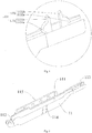
Fig. 1 is a schematic view of a hinge assembly for a dishwasher according to a first embodiment of the present disclosure; -
Fig. 2 is a schematic view of a hinge of the hinge assembly for a dishwasher according to the first embodiment of the present disclosure; -
Fig. 3 is a schematic view of a hinge friction sleeve of the hinge assembly for a dishwasher according to the first embodiment of the present disclosure; -
Fig. 4 is a partially enlarged view of portion "A" inFig. 3 ; -
Fig. 5 is another schematic view of the hinge friction sleeve of the hinge assembly for the dishwasher according to the first embodiment of the present disclosure; and -
Fig. 6 is a schematic view of a dishwasher according to an embodiment of the present disclosure. - Embodiments of the present disclosure will be described in detail. Examples of the embodiments are shown in the drawings. The same or similar elements and the elements having same or similar functions are denoted by like reference numerals throughout the descriptions. The embodiments described herein with reference to drawings are explanatory, and used to generally understand the present disclosure, and shall not be construed to limit the present disclosure.
- In the following, a
hinge assembly 100 for a dishwasher according to embodiments of the present disclosure will be described in detail with reference to the drawings. - As shown in
Figs. 1 to 6 , thehinge assembly 100 according to embodiments of the present disclosure includes: ahinge friction sleeve 11 and an L-shaped hinge 12. - Specifically, the
hinge friction sleeve 11 has aninserting groove 111 extending along a length direction of the hinge friction sleeve 11 (i.e. a direction indicated by the left and right arrow shown inFig. 3 ). A first end (i.e. a left end of theinserting groove 111 shown inFig. 3 ) of theinserting groove 111 is provided with a snap-fitting rod 112, and a second end (i.e. a right end of theinserting groove 111 shown inFig. 3 ) of theinserting groove 111 is provided with a snap-fitting portion 113. - As shown in
Fig. 2 , the L-shaped hinge 12 has ahorizontal limb 121 fitted within theinserting groove 111. Thehorizontal limb 121 of the L-shaped hinge 12 has a first end (i.e. a left end of thehorizontal limb 121 shown inFig. 2 ) snap-fitted with the snap-fitting rod 112 and a second end (i.e. a right end of thehorizontal limb 121 shown inFig. 2 ) provided with an openaxial groove 1212 fitted with the snap-fitting portion 113. The snap-fittingportion 113 is snap-fitted within the openaxial groove 1212 to close an opening of the openaxial groove 1212. An upper edge of the open axial groove is spaced apart from an upper edge of the snap-fittingportion 113 at a predetermined distance to accommodate a rotating shaft of the dishwasher. - More specifically, as shown in
Fig. 2 , according to an embodiment of the present disclosure, a left side wall of the openaxial groove 1212 is provided with a firstconcave portion 1212a and a right side wall of the openaxial groove 1212 is provided with a secondconcave portion 1212b. - As shown in
Fig. 4 , the snap-fitting portion 113 includes a left snapping leg 1131 and aright snapping leg 1132. The left snapping leg 1131 has a first convex hook 1131a fitted with the firstconcave portion 1212a, and theright snapping leg 1132 has asecond convex hook 1132a fitted with the second concave portion 1212b.That is, when the snap-fittingportion 113 is inserted into the openaxial groove 1212, the first convex hook 1131a is snap-fitted within the firstconcave portion 1212a and thesecond convex hook 1132a is snap-fitted within the secondconcave portion 1212b. - Advantageously, according to an embodiment of the present disclosure, the first convex hook 1131a has a first branch leg 1131b thereon and the
second convex hook 1132a has asecond branch leg 1132b thereon. Further, respective upper edges of the first branch leg 1131b and thesecond branch leg 1132b are rounded off. Thus, when the rotatingshaft 201 of the dishwasher is fitted within a space defined by the openaxial groove 1212 and the snap-fittingportion 113, thehinge assembly 100 for the dishwasher according to embodiments of the present disclosure may rotate more flexibly. - As shown in
Fig. 2 , according to an embodiment of the present disclosure, the first end of thehorizontal limb 121 of the L-shaped hinge 12 has asnap hook 1211 fitted with the snap-fitting rod 112. Advantageously, thesnap hook 1211 is a U-shaped snap hook and a section of the snap-fitting rod 112 is shaped as a semicircle or a circle. Thus, the snap fitting is firm. - An assembling process of the
hinge assembly 100 used for the dishwasher according to embodiments of the present disclosure will be simply introduced in the following. - The
hinge friction sleeve 11 and the L-shaped hinge 12 are provided. Firstly, the first end of the L-shaped hinge 12 passes through theinserting groove 111 of thehinge friction sleeve 11, and hence thesnap hook 1211 is snap-fitted with the snap-fitting rod 112. Then, thehinge friction sleeve 11 is rotated around the snap-fitting rod 112 so as to make the snap-fittingportion 113 snap-fitted with the openaxial groove 1212. Thus, the assembling of thehinge assembly 100 according to embodiments of the present disclosure is finished. - A disassembling process of the
hinge assembly 100 used for the dishwasher according to embodiments of the present disclosure is the reverse process of the assembling process, which will not be described herein. - In the hinge assembly according to embodiments of the present disclosure, the first end of the horizontal limb of the L-shaped hinge is snap-fitted with the snap-fitting rod of the hinge friction sleeve, and the second end of the horizontal limb of the L-shaped hinge is snap-fitted with the snap-fitting portion of the hinge friction sleeve, which is simple in structure and convenient to assemble and disassemble, and has a high production efficiency.
- As shown in
Fig. 3 , according to an embodiment of the present disclosure, a front surface of thehinge friction sleeve 11 has aconvex rib 114 thereon. Advantageously, a plurality of theconvex ribs 114 are provided and spaced apart evenly along the length direction of thehinge friction sleeve 11. Thus, thehinge assembly 100 according to embodiments of the present disclosure is in line contact with other components when rotating, which reduces a friction area. - As shown in
Fig. 5 , according to an embodiment of the present disclosure, a rear surface of thehinge friction sleeve 11 has a supportingboss 115 thereon, to serve as a support for the other components of the dishwasher. - It shall be noted that, the hinge friction sleeve may be integrally molded from modified poly butylene terephthalate (MPBT) or polyoxymethylene (POM), which is molded easily at a low cost.
- As shown in
Fig. 6 , the dishwasher according to embodiments of the present disclosure includes aninner tank 200 provided with adishwasher shaft 201, and thehinge assembly 100 used for the dishwasher according to embodiments of the present disclosure is pivotably mounted onto thedishwasher shaft 201. Adoor body 300 is mounted onto avertical limb 122 of the L-shapedhinge 12 of thehinge assembly 100 according to embodiments of the present disclosure. - Specifically, first the open
axial groove 1212 of the L-shapedhinge 12 is snapped onto thedishwasher shaft 201, then the first end of the L-shapedhinge 12 passes through the insertinggroove 111 of thehinge friction sleeve 11, and hence thesnap hook 1211 is snap-fitted with the snap-fittingrod 112. Finally, thehinge friction sleeve 11 is rotated around the snap-fittingrod 112 so as to make the snap-fitting portion 113 snap-fitted with the openaxial groove 1212. Consequently, thedishwasher shaft 201 is surrounded by the openaxial groove 1212 and the snap-fitting portion 113. - Based on the structure of the L-shaped
hinge 12, thehinge assembly 100 according to embodiments of the present disclosure can rotate around thedishwasher shaft 201 for 90 degrees so as to implement actions of opening and closing the door. - The
hinge assembly 100 used for the dishwasher according to embodiments of the present disclosure is simple in structure, convenient and reliable to assemble and disassemble, which improves the production efficiency greatly and saves the cost. - Although embodiments have been shown and described, it would be appreciated that the embodiments above are explanatory and cannot be construed to limit the present disclosure, and changes, alternatives, transformation and modifications to the embodiments above can be made by those skilled in the art in the scope of the apended claims.
Claims (10)
- A hinge assembly (100) for a dishwasher, the hinge assembly comprising:a hinge friction sleeve (11) having an inserting groove (111), wherein the inserting groove (111) extends along a length direction of the hinge friction sleeve (11) and has a first end provided with a snap-fitting rod (112) and a second end provided with a snap-fitting portion (113); andan L-shaped hinge (12) having a horizontal limb (121) fitted within the inserting groove (111), wherein the horizontal limb (121) has a first end snap-fitted with the snap-fitting rod (112) and a second end provided with an open axial groove (1212) fitted with the snap-fitting portion (113), the snap-fitting portion (113) is snap-fitted within the open axial groove (1212) to close an opening of the open axial groove (1212), and an upper edge of the open axial groove (1212) is spaced apart from an upper edge of the snap-fitting portion (113) at a predetermined distance;wherein the hinge friction sleeve (11) and the L-shaped hinge (12) are configured to be fixed to the dishwasher and the hinge assembly (100) is configured to be pivotably mounted onto a dishwasher shaft (201); a door body 300 of the dishwasher is configured to be mountable onto a vertical limb (122) of the L-shaped hinge (12), and the open axial groove (1212) of the L-shaped hinge (12) is snapped onto the dishwasher shaft (201) that is provided with an inner tank (200) of the dishwasher, such that the dishwasher shaft (201) is surrounded by the open axial groove (1212) and the snap-fitting portion (113).
- The hinge assembly (100) according to claim 1, wherein a left side wall of the open axial groove (1212) is provided with a first concave portion (1212a) and a right side wall thereof is provided with a second concave portion (1212b), and the snap-fitting portion (113) comprises a left snapping leg (1131) having a first convex hook (1131a) fitted with the first concave portion (1212a) and a right snapping leg (1132) having a second convex hook (1132a) fitted with the second concave portion (1212b).
- The hinge assembly (100) according to claim 2, wherein the first convex hook (1131a) has a first branch leg (1131b) thereon and the second convex hook (1132a) has a second branch leg (1132b) thereon.
- The hinge assembly (100) according to claim 3, wherein respective upper edges of the first branch leg (1131b) and the second branch leg (1132b) are rounded off.
- The hinge assembly (100) according to claim 1, wherein the first end of the horizontal limb (121) of the L-shaped hinge (12) has a snap hook (1211) fitted with the snap-fitting rod (112).
- The hinge assembly (100) according to claim 5, wherein the snap hook (1211) is a U-shaped snap hook, and a section of the snap-fitting rod (112) is shaped as a semicircle or a circle.
- The hinge assembly (100) according to claim 1, wherein a front surface of the hinge friction sleeve (11) has a convex rib (114) thereon.
- The hinge assembly (100) according to claim 7, wherein a plurality of the convex ribs (114) are provided and spaced apart evenly along the length direction of the hinge friction sleeve (11).
- The hinge assembly (100) according to claim 7, wherein a rear surface of the hinge friction sleeve (11) has a supporting boss (115) thereon.
- A dishwasher, characterized in that the dishwasher comprises a hinge assembly (100) for a dishwasher according to any one of claims 1-9.
Applications Claiming Priority (3)
| Application Number | Priority Date | Filing Date | Title |
|---|---|---|---|
| CN201410119695.5A CN104948049B (en) | 2014-03-27 | 2014-03-27 | Dish washing machine and hinge assembly thereof |
| CN201420144512.0U CN203755865U (en) | 2014-03-27 | 2014-03-27 | Dish washing machine and hinge component thereof |
| PCT/CN2014/092710 WO2015143889A1 (en) | 2014-03-27 | 2014-12-01 | Dishwasher and hinge assembly thereof |
Publications (3)
| Publication Number | Publication Date |
|---|---|
| EP3124728A1 EP3124728A1 (en) | 2017-02-01 |
| EP3124728A4 EP3124728A4 (en) | 2017-11-29 |
| EP3124728B1 true EP3124728B1 (en) | 2020-04-01 |
Family
ID=54193971
Family Applications (1)
| Application Number | Title | Priority Date | Filing Date |
|---|---|---|---|
| EP14887544.6A Active EP3124728B1 (en) | 2014-03-27 | 2014-12-01 | Dishwasher and hinge assembly thereof |
Country Status (4)
| Country | Link |
|---|---|
| US (1) | US9693671B2 (en) |
| EP (1) | EP3124728B1 (en) |
| ES (1) | ES2793937T3 (en) |
| WO (1) | WO2015143889A1 (en) |
Families Citing this family (2)
| Publication number | Priority date | Publication date | Assignee | Title |
|---|---|---|---|---|
| US10231595B2 (en) * | 2015-09-29 | 2019-03-19 | Haier Us Appliance Solutions, Inc. | Appliance with a pin retention feature |
| CN111721125B (en) * | 2020-07-01 | 2024-09-13 | 中国联合工程有限公司 | Industrial furnace and working method thereof |
Family Cites Families (25)
| Publication number | Priority date | Publication date | Assignee | Title |
|---|---|---|---|---|
| US3889654A (en) * | 1973-12-26 | 1975-06-17 | Kelvinator Inc | Self-locking oven door hinge |
| US4437529A (en) * | 1982-05-03 | 1984-03-20 | Ingersoll Equipment Co., Inc. | Detachable hinge assembly |
| US4731903A (en) * | 1986-10-27 | 1988-03-22 | White Consolidated Industries, Inc. | Self-latching hinge |
| US5040269A (en) * | 1990-03-08 | 1991-08-20 | The Bilco Company | Attachment mechanism with double lip lock |
| US5193308A (en) * | 1992-07-22 | 1993-03-16 | The Stanley Works | Snap-in hinge for doors with hollow metal frames |
| KR0169462B1 (en) * | 1996-10-08 | 1999-10-01 | 삼성전자주식회사 | Refrigerator |
| DE29621599U1 (en) * | 1996-12-12 | 1997-02-27 | BSH Bosch und Siemens Hausgeräte GmbH, 81669 München | Door hinge for front-loading household appliances |
| US6099097A (en) * | 1997-06-26 | 2000-08-08 | Sun Microsystems, Inc. | Snap-fit door hinge assembly and method |
| KR100267936B1 (en) * | 1997-11-22 | 2000-11-01 | 윤종용 | Refrigerator |
| US6311935B1 (en) * | 1999-07-07 | 2001-11-06 | Heyco Products, Inc. | Cable clamp |
| US6461026B1 (en) * | 2001-05-08 | 2002-10-08 | Hubbell Incorporated | Luminaire centering hinge |
| DE10259065B4 (en) * | 2002-12-17 | 2011-04-28 | BSH Bosch und Siemens Hausgeräte GmbH | Door hinge and bearing bush |
| US20040216274A1 (en) * | 2003-05-01 | 2004-11-04 | Morgan Charles E. | Releasable hinge clamp |
| US7346959B2 (en) * | 2004-02-27 | 2008-03-25 | Newell Operating Company | Hinge |
| KR100658851B1 (en) * | 2005-01-25 | 2006-12-15 | 엘지전자 주식회사 | Door assembly structure of the dishwasher |
| WO2007013953A1 (en) * | 2005-07-20 | 2007-02-01 | Newfrey Llc | Hinged clip having a retainer |
| US20110187246A1 (en) * | 2006-02-22 | 2011-08-04 | Shin Gap Su | Dish Washer |
| KR20070084898A (en) * | 2006-02-22 | 2007-08-27 | 엘지전자 주식회사 | Door hinge assembly of dishwasher |
| DE102007017270A1 (en) * | 2007-04-12 | 2008-10-30 | BSH Bosch und Siemens Hausgeräte GmbH | Household appliance i.e. dishwasher, has container and door connected together by hinge in pivotably movable manner, and hinge undetachably partially connected with appliance, where door and hinge lever are connected with each other |
| US8231738B2 (en) * | 2007-07-02 | 2012-07-31 | Electrolux Home Products, Inc. | Dishwasher tub having integral hinge support member, and dishwasher incorporating same |
| US8250707B2 (en) * | 2009-03-10 | 2012-08-28 | Electrolux Home Products, Inc. | Door hinge assembly with intermediate stop position |
| US8266765B2 (en) * | 2009-03-11 | 2012-09-18 | Electrolux Home Products, Inc. | Appliance door hinge |
| CN201416331Y (en) * | 2009-04-26 | 2010-03-03 | 美的集团有限公司 | Door hinge device of dish washer |
| US9267633B2 (en) * | 2013-03-12 | 2016-02-23 | Bsh Home Appliances Corporation | Hose lock with living hinge, home appliance including hose lock with living hinge and method of assembling home appliance including hose lock with living hinge |
| CN203755865U (en) * | 2014-03-27 | 2014-08-06 | 美的集团股份有限公司 | Dish washing machine and hinge component thereof |
-
2014
- 2014-12-01 EP EP14887544.6A patent/EP3124728B1/en active Active
- 2014-12-01 ES ES14887544T patent/ES2793937T3/en active Active
- 2014-12-01 US US15/129,491 patent/US9693671B2/en not_active Expired - Fee Related
- 2014-12-01 WO PCT/CN2014/092710 patent/WO2015143889A1/en not_active Ceased
Non-Patent Citations (1)
| Title |
|---|
| None * |
Also Published As
| Publication number | Publication date |
|---|---|
| US9693671B2 (en) | 2017-07-04 |
| WO2015143889A1 (en) | 2015-10-01 |
| EP3124728A1 (en) | 2017-02-01 |
| EP3124728A4 (en) | 2017-11-29 |
| ES2793937T3 (en) | 2020-11-17 |
| US20170105598A1 (en) | 2017-04-20 |
Similar Documents
| Publication | Publication Date | Title |
|---|---|---|
| EP2457489B1 (en) | Table top dishwasher | |
| US20110187246A1 (en) | Dish Washer | |
| CN203755865U (en) | Dish washing machine and hinge component thereof | |
| US7765643B2 (en) | Connection for hinge | |
| EP1894509B1 (en) | Built-in domestic appliance with decorative panel applied to the door | |
| EP3124728A1 (en) | Dishwasher and hinge assembly thereof | |
| CN203810556U (en) | Air conditioner indoor unit and air conditioner | |
| WO2018001509A1 (en) | Warming drawer with an improved sealing perfomance | |
| CN205037678U (en) | Refrigerator and refrigerator door pallet component thereof | |
| US10194494B2 (en) | Microwave cooking device | |
| CN111195113B (en) | Door hinge for dish washing machine and dish washing machine | |
| US20160037995A1 (en) | A household appliance comprising a lock | |
| CN104948049B (en) | Dish washing machine and hinge assembly thereof | |
| CN204683525U (en) | The assembly structure of panel and external door and dish-washing machine | |
| CN203518163U (en) | Panel opening mechanism and air conditioner with same | |
| CN210930933U (en) | Uncap structure and cooking utensil | |
| CN204060265U (en) | Hinge and home appliances | |
| CN203669626U (en) | Box door assembly structure | |
| CN217447447U (en) | Heating tube, oven subassembly and oven | |
| CN109691954B (en) | Dish-washing machine | |
| CN205351574U (en) | Automatically controlled box and air condensing units | |
| CN224107059U (en) | A door with a concealed door handle and a household appliance | |
| CN224085272U (en) | Linkage hinge | |
| CN215650596U (en) | Flip formula casing and domestic appliance | |
| CN211549257U (en) | Damping limiting type water tank door and cooking device |
Legal Events
| Date | Code | Title | Description |
|---|---|---|---|
| PUAI | Public reference made under article 153(3) epc to a published international application that has entered the european phase |
Free format text: ORIGINAL CODE: 0009012 |
|
| STAA | Information on the status of an ep patent application or granted ep patent |
Free format text: STATUS: REQUEST FOR EXAMINATION WAS MADE |
|
| 17P | Request for examination filed |
Effective date: 20160923 |
|
| AK | Designated contracting states |
Kind code of ref document: A1 Designated state(s): AL AT BE BG CH CY CZ DE DK EE ES FI FR GB GR HR HU IE IS IT LI LT LU LV MC MK MT NL NO PL PT RO RS SE SI SK SM TR |
|
| AX | Request for extension of the european patent |
Extension state: BA ME |
|
| DAX | Request for extension of the european patent (deleted) | ||
| A4 | Supplementary search report drawn up and despatched |
Effective date: 20171102 |
|
| RIC1 | Information provided on ipc code assigned before grant |
Ipc: E05D 11/08 20060101ALI20171025BHEP Ipc: E05D 5/16 20060101ALN20171025BHEP Ipc: E05D 5/02 20060101AFI20171025BHEP |
|
| STAA | Information on the status of an ep patent application or granted ep patent |
Free format text: STATUS: EXAMINATION IS IN PROGRESS |
|
| 17Q | First examination report despatched |
Effective date: 20181106 |
|
| GRAP | Despatch of communication of intention to grant a patent |
Free format text: ORIGINAL CODE: EPIDOSNIGR1 |
|
| RIC1 | Information provided on ipc code assigned before grant |
Ipc: E05D 5/02 20060101AFI20190926BHEP Ipc: E05D 11/08 20060101ALI20190926BHEP Ipc: E05D 5/16 20060101ALN20190926BHEP |
|
| STAA | Information on the status of an ep patent application or granted ep patent |
Free format text: STATUS: GRANT OF PATENT IS INTENDED |
|
| INTG | Intention to grant announced |
Effective date: 20191031 |
|
| GRAS | Grant fee paid |
Free format text: ORIGINAL CODE: EPIDOSNIGR3 |
|
| GRAA | (expected) grant |
Free format text: ORIGINAL CODE: 0009210 |
|
| STAA | Information on the status of an ep patent application or granted ep patent |
Free format text: STATUS: THE PATENT HAS BEEN GRANTED |
|
| AK | Designated contracting states |
Kind code of ref document: B1 Designated state(s): AL AT BE BG CH CY CZ DE DK EE ES FI FR GB GR HR HU IE IS IT LI LT LU LV MC MK MT NL NO PL PT RO RS SE SI SK SM TR |
|
| REG | Reference to a national code |
Ref country code: GB Ref legal event code: FG4D |
|
| REG | Reference to a national code |
Ref country code: AT Ref legal event code: REF Ref document number: 1251524 Country of ref document: AT Kind code of ref document: T Effective date: 20200415 Ref country code: CH Ref legal event code: EP |
|
| REG | Reference to a national code |
Ref country code: DE Ref legal event code: R096 Ref document number: 602014063338 Country of ref document: DE |
|
| REG | Reference to a national code |
Ref country code: IE Ref legal event code: FG4D |
|
| PG25 | Lapsed in a contracting state [announced via postgrant information from national office to epo] |
Ref country code: BG Free format text: LAPSE BECAUSE OF FAILURE TO SUBMIT A TRANSLATION OF THE DESCRIPTION OR TO PAY THE FEE WITHIN THE PRESCRIBED TIME-LIMIT Effective date: 20200701 |
|
| REG | Reference to a national code |
Ref country code: NL Ref legal event code: MP Effective date: 20200401 |
|
| REG | Reference to a national code |
Ref country code: LT Ref legal event code: MG4D |
|
| PG25 | Lapsed in a contracting state [announced via postgrant information from national office to epo] |
Ref country code: NO Free format text: LAPSE BECAUSE OF FAILURE TO SUBMIT A TRANSLATION OF THE DESCRIPTION OR TO PAY THE FEE WITHIN THE PRESCRIBED TIME-LIMIT Effective date: 20200701 Ref country code: GR Free format text: LAPSE BECAUSE OF FAILURE TO SUBMIT A TRANSLATION OF THE DESCRIPTION OR TO PAY THE FEE WITHIN THE PRESCRIBED TIME-LIMIT Effective date: 20200702 Ref country code: CZ Free format text: LAPSE BECAUSE OF FAILURE TO SUBMIT A TRANSLATION OF THE DESCRIPTION OR TO PAY THE FEE WITHIN THE PRESCRIBED TIME-LIMIT Effective date: 20200401 Ref country code: FI Free format text: LAPSE BECAUSE OF FAILURE TO SUBMIT A TRANSLATION OF THE DESCRIPTION OR TO PAY THE FEE WITHIN THE PRESCRIBED TIME-LIMIT Effective date: 20200401 Ref country code: IS Free format text: LAPSE BECAUSE OF FAILURE TO SUBMIT A TRANSLATION OF THE DESCRIPTION OR TO PAY THE FEE WITHIN THE PRESCRIBED TIME-LIMIT Effective date: 20200801 Ref country code: NL Free format text: LAPSE BECAUSE OF FAILURE TO SUBMIT A TRANSLATION OF THE DESCRIPTION OR TO PAY THE FEE WITHIN THE PRESCRIBED TIME-LIMIT Effective date: 20200401 Ref country code: PT Free format text: LAPSE BECAUSE OF FAILURE TO SUBMIT A TRANSLATION OF THE DESCRIPTION OR TO PAY THE FEE WITHIN THE PRESCRIBED TIME-LIMIT Effective date: 20200817 Ref country code: LT Free format text: LAPSE BECAUSE OF FAILURE TO SUBMIT A TRANSLATION OF THE DESCRIPTION OR TO PAY THE FEE WITHIN THE PRESCRIBED TIME-LIMIT Effective date: 20200401 Ref country code: SE Free format text: LAPSE BECAUSE OF FAILURE TO SUBMIT A TRANSLATION OF THE DESCRIPTION OR TO PAY THE FEE WITHIN THE PRESCRIBED TIME-LIMIT Effective date: 20200401 |
|
| REG | Reference to a national code |
Ref country code: AT Ref legal event code: MK05 Ref document number: 1251524 Country of ref document: AT Kind code of ref document: T Effective date: 20200401 |
|
| REG | Reference to a national code |
Ref country code: ES Ref legal event code: FG2A Ref document number: 2793937 Country of ref document: ES Kind code of ref document: T3 Effective date: 20201117 |
|
| PG25 | Lapsed in a contracting state [announced via postgrant information from national office to epo] |
Ref country code: HR Free format text: LAPSE BECAUSE OF FAILURE TO SUBMIT A TRANSLATION OF THE DESCRIPTION OR TO PAY THE FEE WITHIN THE PRESCRIBED TIME-LIMIT Effective date: 20200401 Ref country code: RS Free format text: LAPSE BECAUSE OF FAILURE TO SUBMIT A TRANSLATION OF THE DESCRIPTION OR TO PAY THE FEE WITHIN THE PRESCRIBED TIME-LIMIT Effective date: 20200401 Ref country code: LV Free format text: LAPSE BECAUSE OF FAILURE TO SUBMIT A TRANSLATION OF THE DESCRIPTION OR TO PAY THE FEE WITHIN THE PRESCRIBED TIME-LIMIT Effective date: 20200401 |
|
| PG25 | Lapsed in a contracting state [announced via postgrant information from national office to epo] |
Ref country code: AL Free format text: LAPSE BECAUSE OF FAILURE TO SUBMIT A TRANSLATION OF THE DESCRIPTION OR TO PAY THE FEE WITHIN THE PRESCRIBED TIME-LIMIT Effective date: 20200401 |
|
| REG | Reference to a national code |
Ref country code: DE Ref legal event code: R097 Ref document number: 602014063338 Country of ref document: DE Ref country code: DE Ref legal event code: R082 Ref document number: 602014063338 Country of ref document: DE Representative=s name: HL KEMPNER PATENTANWALT, RECHTSANWALT, SOLICIT, DE Ref country code: DE Ref legal event code: R082 Ref document number: 602014063338 Country of ref document: DE Representative=s name: HL KEMPNER PATENTANWAELTE, SOLICITORS (ENGLAND, DE Ref country code: DE Ref legal event code: R082 Ref document number: 602014063338 Country of ref document: DE Representative=s name: HL KEMPNER PARTG MBB, DE Ref country code: DE Ref legal event code: R082 Ref document number: 602014063338 Country of ref document: DE Representative=s name: MAUCHER JENKINS PATENTANWAELTE & RECHTSANWAELT, DE |
|
| PG25 | Lapsed in a contracting state [announced via postgrant information from national office to epo] |
Ref country code: DK Free format text: LAPSE BECAUSE OF FAILURE TO SUBMIT A TRANSLATION OF THE DESCRIPTION OR TO PAY THE FEE WITHIN THE PRESCRIBED TIME-LIMIT Effective date: 20200401 Ref country code: AT Free format text: LAPSE BECAUSE OF FAILURE TO SUBMIT A TRANSLATION OF THE DESCRIPTION OR TO PAY THE FEE WITHIN THE PRESCRIBED TIME-LIMIT Effective date: 20200401 Ref country code: EE Free format text: LAPSE BECAUSE OF FAILURE TO SUBMIT A TRANSLATION OF THE DESCRIPTION OR TO PAY THE FEE WITHIN THE PRESCRIBED TIME-LIMIT Effective date: 20200401 Ref country code: SM Free format text: LAPSE BECAUSE OF FAILURE TO SUBMIT A TRANSLATION OF THE DESCRIPTION OR TO PAY THE FEE WITHIN THE PRESCRIBED TIME-LIMIT Effective date: 20200401 Ref country code: RO Free format text: LAPSE BECAUSE OF FAILURE TO SUBMIT A TRANSLATION OF THE DESCRIPTION OR TO PAY THE FEE WITHIN THE PRESCRIBED TIME-LIMIT Effective date: 20200401 Ref country code: IT Free format text: LAPSE BECAUSE OF FAILURE TO SUBMIT A TRANSLATION OF THE DESCRIPTION OR TO PAY THE FEE WITHIN THE PRESCRIBED TIME-LIMIT Effective date: 20200401 |
|
| PLBE | No opposition filed within time limit |
Free format text: ORIGINAL CODE: 0009261 |
|
| STAA | Information on the status of an ep patent application or granted ep patent |
Free format text: STATUS: NO OPPOSITION FILED WITHIN TIME LIMIT |
|
| PG25 | Lapsed in a contracting state [announced via postgrant information from national office to epo] |
Ref country code: SK Free format text: LAPSE BECAUSE OF FAILURE TO SUBMIT A TRANSLATION OF THE DESCRIPTION OR TO PAY THE FEE WITHIN THE PRESCRIBED TIME-LIMIT Effective date: 20200401 Ref country code: PL Free format text: LAPSE BECAUSE OF FAILURE TO SUBMIT A TRANSLATION OF THE DESCRIPTION OR TO PAY THE FEE WITHIN THE PRESCRIBED TIME-LIMIT Effective date: 20200401 |
|
| 26N | No opposition filed |
Effective date: 20210112 |
|
| PG25 | Lapsed in a contracting state [announced via postgrant information from national office to epo] |
Ref country code: SI Free format text: LAPSE BECAUSE OF FAILURE TO SUBMIT A TRANSLATION OF THE DESCRIPTION OR TO PAY THE FEE WITHIN THE PRESCRIBED TIME-LIMIT Effective date: 20200401 |
|
| REG | Reference to a national code |
Ref country code: CH Ref legal event code: PL |
|
| PG25 | Lapsed in a contracting state [announced via postgrant information from national office to epo] |
Ref country code: MC Free format text: LAPSE BECAUSE OF FAILURE TO SUBMIT A TRANSLATION OF THE DESCRIPTION OR TO PAY THE FEE WITHIN THE PRESCRIBED TIME-LIMIT Effective date: 20200401 |
|
| REG | Reference to a national code |
Ref country code: BE Ref legal event code: MM Effective date: 20201231 |
|
| PG25 | Lapsed in a contracting state [announced via postgrant information from national office to epo] |
Ref country code: IE Free format text: LAPSE BECAUSE OF NON-PAYMENT OF DUE FEES Effective date: 20201201 Ref country code: LU Free format text: LAPSE BECAUSE OF NON-PAYMENT OF DUE FEES Effective date: 20201201 |
|
| PG25 | Lapsed in a contracting state [announced via postgrant information from national office to epo] |
Ref country code: CH Free format text: LAPSE BECAUSE OF NON-PAYMENT OF DUE FEES Effective date: 20201231 Ref country code: LI Free format text: LAPSE BECAUSE OF NON-PAYMENT OF DUE FEES Effective date: 20201231 |
|
| PGFP | Annual fee paid to national office [announced via postgrant information from national office to epo] |
Ref country code: GB Payment date: 20211111 Year of fee payment: 8 Ref country code: FR Payment date: 20211116 Year of fee payment: 8 |
|
| PG25 | Lapsed in a contracting state [announced via postgrant information from national office to epo] |
Ref country code: TR Free format text: LAPSE BECAUSE OF FAILURE TO SUBMIT A TRANSLATION OF THE DESCRIPTION OR TO PAY THE FEE WITHIN THE PRESCRIBED TIME-LIMIT Effective date: 20200401 Ref country code: MT Free format text: LAPSE BECAUSE OF FAILURE TO SUBMIT A TRANSLATION OF THE DESCRIPTION OR TO PAY THE FEE WITHIN THE PRESCRIBED TIME-LIMIT Effective date: 20200401 Ref country code: CY Free format text: LAPSE BECAUSE OF FAILURE TO SUBMIT A TRANSLATION OF THE DESCRIPTION OR TO PAY THE FEE WITHIN THE PRESCRIBED TIME-LIMIT Effective date: 20200401 |
|
| PGFP | Annual fee paid to national office [announced via postgrant information from national office to epo] |
Ref country code: ES Payment date: 20220105 Year of fee payment: 8 |
|
| PG25 | Lapsed in a contracting state [announced via postgrant information from national office to epo] |
Ref country code: MK Free format text: LAPSE BECAUSE OF FAILURE TO SUBMIT A TRANSLATION OF THE DESCRIPTION OR TO PAY THE FEE WITHIN THE PRESCRIBED TIME-LIMIT Effective date: 20200401 |
|
| PG25 | Lapsed in a contracting state [announced via postgrant information from national office to epo] |
Ref country code: BE Free format text: LAPSE BECAUSE OF NON-PAYMENT OF DUE FEES Effective date: 20201231 |
|
| P01 | Opt-out of the competence of the unified patent court (upc) registered |
Effective date: 20230526 |
|
| GBPC | Gb: european patent ceased through non-payment of renewal fee |
Effective date: 20221201 |
|
| PG25 | Lapsed in a contracting state [announced via postgrant information from national office to epo] |
Ref country code: GB Free format text: LAPSE BECAUSE OF NON-PAYMENT OF DUE FEES Effective date: 20221201 |
|
| PG25 | Lapsed in a contracting state [announced via postgrant information from national office to epo] |
Ref country code: FR Free format text: LAPSE BECAUSE OF NON-PAYMENT OF DUE FEES Effective date: 20221231 |
|
| REG | Reference to a national code |
Ref country code: ES Ref legal event code: FD2A Effective date: 20240126 |
|
| PG25 | Lapsed in a contracting state [announced via postgrant information from national office to epo] |
Ref country code: ES Free format text: LAPSE BECAUSE OF NON-PAYMENT OF DUE FEES Effective date: 20221202 |
|
| PG25 | Lapsed in a contracting state [announced via postgrant information from national office to epo] |
Ref country code: ES Free format text: LAPSE BECAUSE OF NON-PAYMENT OF DUE FEES Effective date: 20221202 |
|
| PGFP | Annual fee paid to national office [announced via postgrant information from national office to epo] |
Ref country code: DE Payment date: 20241216 Year of fee payment: 11 |
|
| REG | Reference to a national code |
Ref country code: DE Ref legal event code: R082 Ref document number: 602014063338 Country of ref document: DE Representative=s name: MAUCHER JENKINS PATENTANWAELTE & RECHTSANWAELT, DE |