EP3124725A1 - A window with an opening restrictor having an activation part - Google Patents
A window with an opening restrictor having an activation part Download PDFInfo
- Publication number
- EP3124725A1 EP3124725A1 EP16179681.8A EP16179681A EP3124725A1 EP 3124725 A1 EP3124725 A1 EP 3124725A1 EP 16179681 A EP16179681 A EP 16179681A EP 3124725 A1 EP3124725 A1 EP 3124725A1
- Authority
- EP
- European Patent Office
- Prior art keywords
- opening
- sash
- window
- arm
- window according
- Prior art date
- Legal status (The legal status is an assumption and is not a legal conclusion. Google has not performed a legal analysis and makes no representation as to the accuracy of the status listed.)
- Granted
Links
Images

Classifications
-
- E—FIXED CONSTRUCTIONS
- E05—LOCKS; KEYS; WINDOW OR DOOR FITTINGS; SAFES
- E05C—BOLTS OR FASTENING DEVICES FOR WINGS, SPECIALLY FOR DOORS OR WINDOWS
- E05C17/00—Devices for holding wings open; Devices for limiting opening of wings or for holding wings open by a movable member extending between frame and wing; Braking devices, stops or buffers, combined therewith
- E05C17/02—Devices for holding wings open; Devices for limiting opening of wings or for holding wings open by a movable member extending between frame and wing; Braking devices, stops or buffers, combined therewith by mechanical means
- E05C17/04—Devices for holding wings open; Devices for limiting opening of wings or for holding wings open by a movable member extending between frame and wing; Braking devices, stops or buffers, combined therewith by mechanical means with a movable bar or equivalent member extending between frame and wing
- E05C17/12—Devices for holding wings open; Devices for limiting opening of wings or for holding wings open by a movable member extending between frame and wing; Braking devices, stops or buffers, combined therewith by mechanical means with a movable bar or equivalent member extending between frame and wing consisting of a single rod
-
- E—FIXED CONSTRUCTIONS
- E05—LOCKS; KEYS; WINDOW OR DOOR FITTINGS; SAFES
- E05C—BOLTS OR FASTENING DEVICES FOR WINGS, SPECIALLY FOR DOORS OR WINDOWS
- E05C17/00—Devices for holding wings open; Devices for limiting opening of wings or for holding wings open by a movable member extending between frame and wing; Braking devices, stops or buffers, combined therewith
- E05C17/02—Devices for holding wings open; Devices for limiting opening of wings or for holding wings open by a movable member extending between frame and wing; Braking devices, stops or buffers, combined therewith by mechanical means
- E05C17/04—Devices for holding wings open; Devices for limiting opening of wings or for holding wings open by a movable member extending between frame and wing; Braking devices, stops or buffers, combined therewith by mechanical means with a movable bar or equivalent member extending between frame and wing
- E05C17/12—Devices for holding wings open; Devices for limiting opening of wings or for holding wings open by a movable member extending between frame and wing; Braking devices, stops or buffers, combined therewith by mechanical means with a movable bar or equivalent member extending between frame and wing consisting of a single rod
- E05C17/14—Hook and eye, or equivalent
-
- E—FIXED CONSTRUCTIONS
- E05—LOCKS; KEYS; WINDOW OR DOOR FITTINGS; SAFES
- E05B—LOCKS; ACCESSORIES THEREFOR; HANDCUFFS
- E05B35/00—Locks for use with special keys or a plurality of keys ; keys therefor
- E05B35/008—Locks for use with special keys or a plurality of keys ; keys therefor for simple tool-like keys
-
- E—FIXED CONSTRUCTIONS
- E05—LOCKS; KEYS; WINDOW OR DOOR FITTINGS; SAFES
- E05C—BOLTS OR FASTENING DEVICES FOR WINGS, SPECIALLY FOR DOORS OR WINDOWS
- E05C17/00—Devices for holding wings open; Devices for limiting opening of wings or for holding wings open by a movable member extending between frame and wing; Braking devices, stops or buffers, combined therewith
- E05C17/02—Devices for holding wings open; Devices for limiting opening of wings or for holding wings open by a movable member extending between frame and wing; Braking devices, stops or buffers, combined therewith by mechanical means
- E05C17/04—Devices for holding wings open; Devices for limiting opening of wings or for holding wings open by a movable member extending between frame and wing; Braking devices, stops or buffers, combined therewith by mechanical means with a movable bar or equivalent member extending between frame and wing
- E05C17/12—Devices for holding wings open; Devices for limiting opening of wings or for holding wings open by a movable member extending between frame and wing; Braking devices, stops or buffers, combined therewith by mechanical means with a movable bar or equivalent member extending between frame and wing consisting of a single rod
- E05C17/16—Devices for holding wings open; Devices for limiting opening of wings or for holding wings open by a movable member extending between frame and wing; Braking devices, stops or buffers, combined therewith by mechanical means with a movable bar or equivalent member extending between frame and wing consisting of a single rod pivoted only at one end and having an elongated slot
-
- E—FIXED CONSTRUCTIONS
- E05—LOCKS; KEYS; WINDOW OR DOOR FITTINGS; SAFES
- E05B—LOCKS; ACCESSORIES THEREFOR; HANDCUFFS
- E05B15/00—Other details of locks; Parts for engagement by bolts of fastening devices
- E05B15/04—Spring arrangements in locks
- E05B2015/0403—Wound springs
- E05B2015/0406—Wound springs wound in a cylindrical shape
- E05B2015/0413—Wound springs wound in a cylindrical shape loaded by compression
Definitions
- the present invention relates to a window configured to be installed in an inclined roof, said window comprising a frame and a sash each having a top member, a bottom member and two side members, the sash being pivotably connected to the frame, such that a pivotal movement of the sash in relation to the frame brings the sash from a closed position to an open position, and comprising an opening restrictor connected to the frame and configured to assume an engaged condition, where the opening restrictor engages an engagement element on the sash, restricting the opening of the sash, and a disengaged condition in which the opening restrictor is configured to be released from said engagement element allowing an opening of the sash.
- Opening restrictors of this kind are well known installations in windows where a limitation of the opening of the sash in relation to the frame is achieved.
- a limitation by an opening restrictor provides the possibility of locking the sash in for example a ventilation position leaving a free airflow into a room.
- conventional opening restrictors also provide for a child safety mechanism, preventing easy and unintended opening of the window.
- Known opening restrictors such as for example described in GB2414513 and GB 2190702 , are typically provided with a base element attached to either the sash of frame part of the window by attachment means. Further attached to the base element is an arm element comprising coupling means.
- the arm and the coupling means may be provided in many different ways and the attachment to the frame or sash, is also seen done in numerous ways.
- the general function of the opening restrictor is that the coupling mechanism of the arm element engages with an engagement element provided on the sash, so as to limit the opening angle of the window or preventing an opening at all.
- opening restrictors require mounting of the base part having the arm, to either a part of the sash or frame and a counterpart, i.e. the engagement element, mounted to the opposite sash or frame.
- This installation often requires the use of a number of mounting elements, such as screws for attaching the base element and/or the engagement element at their respective places on the sash and/or frame.
- the accuracy of the installation of the base element and engagement element in relation to each other is of importance.
- the installation thereof may be a somewhat complicated procedure for a manufacture and/or user installing the opening restrictor.
- screws used for attachment may also appear visible, whether in a closed or an open position of the window creating an unpleasant aesthetic appearance.
- Opening restrictors are thus preferably installed in a hidden position between the frame and sash, where their installation does not obstruct the finish of the frame and/or sash.
- the hidden opening restrictors may cause another drawback in that a disengagement of the opening restrictor, allowing a fully open window, could cause a user to get caught in the "hidden space", in order to disengage the opening restrictor.
- these "hidden" opening restrictors might cause the fingers of the user being caught in the opening restrictor.
- the window according to the present invention is characterised in that the opening restrictor comprises an arm having an activation part configured to, under influence from a pressure-activation of said activation part, activate a spring mechanism engaging said arm for rotation thereof.
- the opening restrictor By configuring the opening restrictor with an activation part, which through a pressure applied to the activation part activates a spring, an easy disengagement of the opening restrictor, is provided for, which at the same time provides for a child safety mechanism.
- the activation part is activated by a user applying a pressure to the activation part, which due to its configuration activates a spring mechanism engaging an arm of the opening restrictor. Due to bias provided by the spring mechanism a rotation of the arm, bringing the arm out of engagement with the engagement element on the sash, is provided for.
- an opening restrictor is provided for which is also easily installed prior to or after mounting of a window, which will become apparent in the following the description.
- said activation part is mounted to the side frame member at an aperture provided in a bottom part of said side frame member. This provides for an easily accessible installation and handling of the opening restrictor in the window.
- said arm comprises a first end and a second end, said first end being configured to engage with said engagement element which is provided on a side sash member, and said second end comprising said activation part is mounted to said side frame member.
- said aperture is preferably provided with a hollow insert, configured to receive said activation part in a mounted condition.
- said activation part comprises a body having a top part and a bottom part, said top part being configured to act upon said pressure-activated force applied to the top part, and influencing a spring connected to said bottom part.
- the spring is in one end is connected to said body, and in a second end, in a mounted condition, received in said hollow insert of said aperture.
- the top part comprises a tool-shaped surface, configured to receive a correspondingly shaped tool, said tool being configured to activate said activation part.
- the tool is a key, said key and the body part of said activation part forming a key and lock mechanism.
- the general structure of a window suitable to be configured with an opening restrictor comprises a stationary frame 4-1, 4-2, 4-3, 4-4 and a sash 4-5, 4-6, 4-7, 4-8, the latter supporting a pane of glass 4-16.
- the frame and the sash each comprises a horizontal bottom member 4-2, 4-6, a pair of parallel side members 4-3, 4-7; 4-4, 4-8 and a horizontal top member 4-1, 4-5 as illustrated in Fig. 8 .
- the frame and sash members are usually made from painted pinewood profiles or from plywood coated with polyurethane, but other embodiments such as all-plastic or aluminium profiles also occur. In most cases the window is openable.
- the sash is then connected with the frame by means of a set of hinge fittings 4-9 defining a hinge axis 4-10, which may be parallel to either the top and bottom members or to the side members.
- the hinge axis may be located closely to the frame and sash either at the top, the bottom or one of the sides, but in common type roof windows it is usually located substantially halfway between the top and bottom members as shown in Fig. 8 .
- the hinge axis may also be displaceable during opening e.g.
- Hinges normally comprise a first hinge part for fastening to the frame, and a second hinge part for fastening to the sash.
- vertical facade windows and top-hung roof windows comprise a handle positioned at a side sash member or at the bottom sash member depending on the location of the hinge axis.
- Said handle provides a locking action of the sash relative to the frame by way of a connected pawl engaging corresponding grooves in a keeper mounted on an adjacent frame member.
- Locking mechanisms of this type are commonly known as cremone bolts.
- Centrehung roof windows are opened and closed by means of an operator member, which is accessible from the inside of the window and usually arranged at the top sash member.
- the window may be equipped with an opening restrictor as the one disclosed herewith.
- each of the frame and sash members are shielded from the weather by means of a series of covering members usually made from thin metal sheeting.
- the covering usually comprises a hood-like upper covering cap (not shown) for covering the frame top member 4-1, a glazing profile 4-15 for covering the joint between the window pane 4-16 and the sash members 4-5, 4-6, 4-7, 4-8.
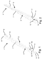
- FIGs 1 to 3 these figures are provided so as to illustrate schematically the different positions and the installation of an opening restrictor in a window according to the invention.
- An opening restrictor generally designated 10 is installed in a window having a general configuration as previously described, here a roof window 1 configured to be installed in an inclined roof and having a frame 2 and a sash 3 each comprising a top member 8, 9, a bottom member 4, 5 and two side members 6, 7.
- the top, bottom and side members 9, 5, 7 of the sash 3 together define a window plane in which a pane 20 is installed.
- the sash 3 is pivotably connected to the frame 2, such that a pivotal opening movement of the sash 3 in relation to the frame 2 brings the sash from a closed position to an open position. In the closed position, the window plane defined by the sash members is substantially parallel with a plane defined by the frame members.
- the pivotal opening movement may either take place about a hinge axis located at the top of the window 1 via a hinge connection (not shown) located at the top members 9, 8 of the sash 3 and frame 2, or about a centre axis via a set of hinges at the side members 7, 6 of the sash 3 and frame 2, or at a position between the top and centre.
- the opening restrictor 10 comprises an arm 11 which is rotatably connected to a bottom part of the side member 6 of the frame 2 via at least one point of rotation.
- a point of rotation is provided by an activation part 17 to be described in further detail below with particular reference to Fig. 7 .
- the opening restrictor 10 is configured to assume the engaged condition of Fig. 2 , where the opening restrictor 10 engages an engagement element 13 provided on the sash 3, thereby restricting the opening of the window, and the disengaged condition of Fig. 1 , in which the opening restrictor 10 is configured to be released from the engagement element 13 allowing a complete opening of the window.
- the opening restrictor 10 is configured so that the activation part 17 is mounted to the side frame member 6 at an aperture 61 provided in a bottom part of said side frame member 6.
- This aperture 61 should preferably be understood as being prefabricated so that it fits the specific dimension of the activation part of the opening restrictor. In this way unnecessary mounting holes, such as those provided by screws or similar tools, does not obstruct the finish of the surface of the frame. Furthermore, this aperture is normally applied for locking the window in a 180 degree cleaning position, why the aperture, at least in most VELUX type roof windows, is already existing. In the commercially available embodiment, there is therefore no need for adapting the fabrication procedures for creating this aperture for installing the opening restrictor of this invention. However, it is of course conceivable to provide such an opening in any suitable manner.
- the general concept of the opening restrictor 10 of the window according to the invention is to provide an opening restrictor which upon a pressure-activation of a spring mechanism 60 may be released from the engaged condition.
- the opening restrictor 10 is therefore furthermore provided with the arm 11 connected to the activation part 17 which is configured to, under influence from a pressure-activation of said activation part, activate spring mechanism 60 engaging the arm 11 for rotation thereof.
- the arm 11 of the opening restrictor 10 comprises a first end 11 a and a second end 11 b, said first end 11 a being configured to engage with the engagement element 13 provided on the side sash member 7, and the second end 11 b comprising the activation part 17 mounted to said side frame member 6.
- the activation part 17 comprises a body 63 having a top part 64 and a bottom part 65, said top part 64 being configured to act upon a pressure-activation, i.e. a force applied to the top part 64, and said bottom part 65 being connected to a spring 66 of the spring mechanism 60.
- the spring 66 is in one end connected to the body 63, and in a second end mounted in the hollow insert 62 of the aperture 61.
- the bottom part 65 is provided with an opening 66 to receive split pin 68 in the mounted condition of the opening restrictor 10.
- the spring 66 Upon applying a force to the top part 64 of the body 63, the spring 66 is activated so as to allow the head part 64 to engage the second end 11 b of the arm, thereby locking the head part 64 to the arm 11.
- the second end 11 b of the arm 11 and the side of the head part 64 facing the second end 11 b of the arm are provided with mutually cooperating engagement means such as counter flanges and/or grooves to engage each other.
- the spring 66 of the spring mechanism 60 is in the disengaged condition compressed due to the locking of the head part 64 to the end 11 b of the arm.
- Bringing the arm 11 back to the engaged condition is achieved by again applying a pressure to the head part 64, wherein the same mechanism of activating the spring 60 and engaging the head part 64 and arm 11 is achieved. As explained previously this allows the head part 64 to rotate the arm 11 back to its engaged condition.
- FIGs 4 to 6 showing different embodiments of a window comprising an opening restrictor
- the general concept of the opening restrictors are similar, i.e. especially the mounting of the restrictors in the aperture 61 and the activation thereof.
- the shape of the opening restrictors may vary and the specific shapes shown should not limit the scope of the invention. Elements having the same or analogous function are denoted by the same reference numerals to which 100, 200 and 300, respectively, have been added.
- opening restrictor according to the embodiments shown in Figs 4 to 6 are all installed in the previous mentioned aperture 61 provided in the side frame member 6.
- This aperture 61 is provided with a hollow insert 62, configured to receive the activation part 17 in a mounted condition, to be explained in more detail in the following.
- the opening restrictor 110 is as in the above-mentioned embodiment arranged in the hollow insert 62 provided in the aperture 61 of the side frame member.
- the arm 111 extends from the activation part 117, and engages engagement element 113 on the side sash member.
- the engagement element 113 is provided as a hollow structure, having an opening 115 intended to receive the arm 111.
- the hollow structure of the engagement element 113 is provided with two opposing walls 116, 117, wherein at least one of said walls 116 comprises a flange 118. As illustrated, the wall 117 and the flange 118 together define the opening 115.
- the walls 116, 117 extend from a bottom part 119 of the engagement element 113, where the bottom part 119 is configured as a mounting surface, for mounting of the engagement element 113 to the side sash member. Furthermore the flange 118 provides for guiding means of the arm 111 during an opening and/or closing of the window.
- the opening restrictor 210 of the embodiment in Fig. 5 comprises an arm 211 extending from the activation part 217.
- the arm 211 is in the engaged condition connected to an engagement element 213.
- the arm 211 has a U-shape, the closed bottom of the U-shape extending towards an interior of the room in which the window is installed and where one open end 211 b of the U connects with the activation part 217, and another end 211 a engages with the engagement element 213 in an engaged condition of the window.
- the engagement element 213 is in this specific embodiment shaped as a box having an opening intended for receiving the first open end 211 a of the arm 211.
- FIG. 6 A further embodiment is illustrated in Fig. 6 .
- the arm 311 is also connected to the aperture 61 of the side frame member 6 through the hollow insert 62.
- the arm 311 of the opening restrictor 310 is in turn connected to an arm 312 of the engagement element 313 to allow rotational movement.
- the activation part of the opening restrictor corresponding to that of Fig. 7
- the top part 64 comprises a tool-shaped surface, configured to receive a corresponding shaped tool, said tool being configured to activate said activation part.
- the tool could be in the shape of a key, wherein the key and the body part of the activation part forms a key and a lock mechanism.
- the key and lock mechanism is only illustrated in one specific embodiment, this should not limit the invention to this specific embodiment.
- the shape of the key-and-lock mechanism could be provided in many ways, such as a regular key-shape, a triangular shape, a rectangular shape or similar.
- the activation part could also be produced without incorporating a key and lock. In this case, a simple pressure on the surface of the top part would activate the opening restrictor.
- the opening restrictor of the present invention With the opening restrictor of the present invention, the risk of a user getting a finger caught in between the sash and frame of the window is minimized. This is due to the opening restrictor being installed on a part of the frame which is not in contact with the sash as such. The opening restrictor may thus be handled easily by a push and twist mechanism.
Landscapes
- Engineering & Computer Science (AREA)
- Mechanical Engineering (AREA)
- Wing Frames And Configurations (AREA)
Description
- The present invention relates to a window configured to be installed in an inclined roof, said window comprising a frame and a sash each having a top member, a bottom member and two side members, the sash being pivotably connected to the frame, such that a pivotal movement of the sash in relation to the frame brings the sash from a closed position to an open position, and comprising an opening restrictor connected to the frame and configured to assume an engaged condition, where the opening restrictor engages an engagement element on the sash, restricting the opening of the sash, and a disengaged condition in which the opening restrictor is configured to be released from said engagement element allowing an opening of the sash.
- Opening restrictors of this kind are well known installations in windows where a limitation of the opening of the sash in relation to the frame is achieved. Conventionally, such limitation by an opening restrictor provides the possibility of locking the sash in for example a ventilation position leaving a free airflow into a room. Furthermore, conventional opening restrictors also provide for a child safety mechanism, preventing easy and unintended opening of the window.
- Known opening restrictors, such as for example described in
GB2414513 GB 2190702 - The installation of such opening restrictors requires mounting of the base part having the arm, to either a part of the sash or frame and a counterpart, i.e. the engagement element, mounted to the opposite sash or frame. This installation often requires the use of a number of mounting elements, such as screws for attaching the base element and/or the engagement element at their respective places on the sash and/or frame. In order for the arm to correctly engage the engagement element, the accuracy of the installation of the base element and engagement element in relation to each other is of importance. Thus, the installation thereof may be a somewhat complicated procedure for a manufacture and/or user installing the opening restrictor. The risk of placing the base element incorrectly in relation to the engagement element easily occurs if even small inaccuracies in the mounted base element and/or engagement element are wrongly measured for. Thus, screw holes could easily be misaligned with each other causing most likely an erroneous installation of the opening restrictor, where the arm having the grip element does not align with the engagement element on the counterpart member, i.e. the sash and/or frame. This causes a potentially re-installation and possibly new screw holes, which complicates the installation process and furthermore provides the sash and/or frame with unintended screw holes, most likely visible from an interior space.
- Furthermore, the screws used for attachment may also appear visible, whether in a closed or an open position of the window creating an unpleasant aesthetic appearance.
- In case of dismounting of the opening restrictor, for example when a child safe installation of the window is no longer needed, the known opening restrictors most often leaves behind the mounting holes, also creating an unpleasant aesthetic appearance.
- Opening restrictors are thus preferably installed in a hidden position between the frame and sash, where their installation does not obstruct the finish of the frame and/or sash. However, the hidden opening restrictors may cause another drawback in that a disengagement of the opening restrictor, allowing a fully open window, could cause a user to get caught in the "hidden space", in order to disengage the opening restrictor. For example these "hidden" opening restrictors might cause the fingers of the user being caught in the opening restrictor.
- Therefore, in light of the above it is the object of the present invention to provide a window of the type mentioned in the introduction having an opening restrictor, which overcomes the above mentioned disadvantages.
- To meet this object the window according to the present invention is characterised in that the opening restrictor comprises an arm having an activation part configured to, under influence from a pressure-activation of said activation part, activate a spring mechanism engaging said arm for rotation thereof.
- By configuring the opening restrictor with an activation part, which through a pressure applied to the activation part activates a spring, an easy disengagement of the opening restrictor, is provided for, which at the same time provides for a child safety mechanism. According to the invention, the activation part is activated by a user applying a pressure to the activation part, which due to its configuration activates a spring mechanism engaging an arm of the opening restrictor. Due to bias provided by the spring mechanism a rotation of the arm, bringing the arm out of engagement with the engagement element on the sash, is provided for.
- Thus, an opening restrictor is provided for which is also easily installed prior to or after mounting of a window, which will become apparent in the following the description.
- In a presently preferred embodiment, said activation part is mounted to the side frame member at an aperture provided in a bottom part of said side frame member. This provides for an easily accessible installation and handling of the opening restrictor in the window.
- In a mechanically simple embodiment, said arm comprises a first end and a second end, said first end being configured to engage with said engagement element which is provided on a side sash member, and said second end comprising said activation part is mounted to said side frame member.
- To render in particular the installation of the opening restrictor easy, said aperture is preferably provided with a hollow insert, configured to receive said activation part in a mounted condition.
- In a presently preferred embodiment, said activation part comprises a body having a top part and a bottom part, said top part being configured to act upon said pressure-activated force applied to the top part, and influencing a spring connected to said bottom part.
- In a further development of the preferred embodiment, the spring is in one end is connected to said body, and in a second end, in a mounted condition, received in said hollow insert of said aperture.
- In an embodiment, which renders operation of the opening restrictor of the window particularly handy, the top part comprises a tool-shaped surface, configured to receive a correspondingly shaped tool, said tool being configured to activate said activation part. Preferably, the tool is a key, said key and the body part of said activation part forming a key and lock mechanism.
- In the following further advantages of the invention will be described in more detail by means of examples of embodiments, with reference to the schematic drawings in which
-
Figs 1 to 2 show schematic illustrations of the general concept of the window including an opening restrictor according to the invention,Fig 1 illustrating the disengaged condition andFig. 2 illustrating the engaged condition; -
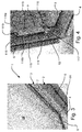
Fig. 3 shows a schematic partial perspective view of a window installed in an inclined roof in an embodiment of the present invention, without the opening restrictor so as to show the aperture provided for mounting of the opening restrictor in the frame of the window; -
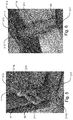
Figs 4 to 6 each shows a view corresponding toFig. 3 , of a window with installed opening restrictor in three embodiments of the invention; -
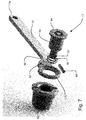
Fig. 7 shows an exploded perspective view of details of a window in a first embodiment of the invention, including components of the spring mechanism and the activation part of the opening restrictor; and -
Fig. 8 is a perspective view illustrating the general construction of a window, whether being top-hung, center-hung or installed in a façade or roof. - Referring initially to
Fig. 8 , the general structure of a window suitable to be configured with an opening restrictor according to the embodiments disclosed herewith comprises a stationary frame 4-1, 4-2, 4-3, 4-4 and a sash 4-5, 4-6, 4-7, 4-8, the latter supporting a pane of glass 4-16. The frame and the sash each comprises a horizontal bottom member 4-2, 4-6, a pair of parallel side members 4-3, 4-7; 4-4, 4-8 and a horizontal top member 4-1, 4-5 as illustrated inFig. 8 . - The frame and sash members are usually made from painted pinewood profiles or from plywood coated with polyurethane, but other embodiments such as all-plastic or aluminium profiles also occur. In most cases the window is openable. The sash is then connected with the frame by means of a set of hinge fittings 4-9 defining a hinge axis 4-10, which may be parallel to either the top and bottom members or to the side members. The hinge axis may be located closely to the frame and sash either at the top, the bottom or one of the sides, but in common type roof windows it is usually located substantially halfway between the top and bottom members as shown in
Fig. 8 . The hinge axis may also be displaceable during opening e.g. by providing the window with a pair of sash arms, which, displaces the centre of rotation e.g. from the top of the window to the centre during opening. Hinges normally comprise a first hinge part for fastening to the frame, and a second hinge part for fastening to the sash. - For opening and closing the window, vertical facade windows and top-hung roof windows comprise a handle positioned at a side sash member or at the bottom sash member depending on the location of the hinge axis. Said handle provides a locking action of the sash relative to the frame by way of a connected pawl engaging corresponding grooves in a keeper mounted on an adjacent frame member. Locking mechanisms of this type are commonly known as cremone bolts.
- Securing of the sash in relation to the frame is often possible in two distinct positions, namely, a closed position and a ventilation position. Centrehung roof windows are opened and closed by means of an operator member, which is accessible from the inside of the window and usually arranged at the top sash member. Furthermore, as will become apparent in the following the window may be equipped with an opening restrictor as the one disclosed herewith.
- On the exterior each of the frame and sash members are shielded from the weather by means of a series of covering members usually made from thin metal sheeting. The covering usually comprises a hood-like upper covering cap (not shown) for covering the frame top member 4-1, a glazing profile 4-15 for covering the joint between the window pane 4-16 and the sash members 4-5, 4-6, 4-7, 4-8.
- Referring now to
Figs 1 to 3 , these figures are provided so as to illustrate schematically the different positions and the installation of an opening restrictor in a window according to the invention. - An opening restrictor generally designated 10 is installed in a window having a general configuration as previously described, here a roof window 1 configured to be installed in an inclined roof and having a
frame 2 and asash 3 each comprising atop member bottom member side members side members sash 3 together define a window plane in which a pane 20 is installed. Thesash 3 is pivotably connected to theframe 2, such that a pivotal opening movement of thesash 3 in relation to theframe 2 brings the sash from a closed position to an open position. In the closed position, the window plane defined by the sash members is substantially parallel with a plane defined by the frame members. The pivotal opening movement may either take place about a hinge axis located at the top of the window 1 via a hinge connection (not shown) located at thetop members sash 3 andframe 2, or about a centre axis via a set of hinges at theside members sash 3 andframe 2, or at a position between the top and centre. - In the embodiment shown, the
opening restrictor 10 comprises anarm 11 which is rotatably connected to a bottom part of theside member 6 of theframe 2 via at least one point of rotation. Here, a point of rotation is provided by anactivation part 17 to be described in further detail below with particular reference toFig. 7 . Theopening restrictor 10 is configured to assume the engaged condition ofFig. 2 , where theopening restrictor 10 engages anengagement element 13 provided on thesash 3, thereby restricting the opening of the window, and the disengaged condition ofFig. 1 , in which theopening restrictor 10 is configured to be released from theengagement element 13 allowing a complete opening of the window. - The opening
restrictor 10 is configured so that theactivation part 17 is mounted to theside frame member 6 at anaperture 61 provided in a bottom part of saidside frame member 6. Thisaperture 61 should preferably be understood as being prefabricated so that it fits the specific dimension of the activation part of the opening restrictor. In this way unnecessary mounting holes, such as those provided by screws or similar tools, does not obstruct the finish of the surface of the frame. Furthermore, this aperture is normally applied for locking the window in a 180 degree cleaning position, why the aperture, at least in most VELUX type roof windows, is already existing. In the commercially available embodiment, there is therefore no need for adapting the fabrication procedures for creating this aperture for installing the opening restrictor of this invention. However, it is of course conceivable to provide such an opening in any suitable manner. - In more detail and referring now also to
Fig. 7 , the general concept of the openingrestrictor 10 of the window according to the invention is to provide an opening restrictor which upon a pressure-activation of aspring mechanism 60 may be released from the engaged condition. The openingrestrictor 10 is therefore furthermore provided with thearm 11 connected to theactivation part 17 which is configured to, under influence from a pressure-activation of said activation part, activatespring mechanism 60 engaging thearm 11 for rotation thereof. - The
arm 11 of the openingrestrictor 10 comprises afirst end 11 a and asecond end 11 b, saidfirst end 11 a being configured to engage with theengagement element 13 provided on theside sash member 7, and thesecond end 11 b comprising theactivation part 17 mounted to saidside frame member 6. As illustrated, theactivation part 17 comprises abody 63 having atop part 64 and abottom part 65, saidtop part 64 being configured to act upon a pressure-activation, i.e. a force applied to thetop part 64, and saidbottom part 65 being connected to aspring 66 of thespring mechanism 60. Thespring 66 is in one end connected to thebody 63, and in a second end mounted in thehollow insert 62 of theaperture 61. Thebottom part 65 is provided with anopening 66 to receivesplit pin 68 in the mounted condition of the openingrestrictor 10. - Upon applying a force to the
top part 64 of thebody 63, thespring 66 is activated so as to allow thehead part 64 to engage thesecond end 11 b of the arm, thereby locking thehead part 64 to thearm 11. Thesecond end 11 b of thearm 11 and the side of thehead part 64 facing thesecond end 11 b of the arm are provided with mutually cooperating engagement means such as counter flanges and/or grooves to engage each other. After the push activation resulting in the locking of thebody 63 to thearm 11, a subsequent rotation of thehead part 64 thus forces thearm 11 to rotate along with thehead part 64, thereby causing release of thearm 11 from theengagement element 13, when rotating thehead part 64. - The
spring 66 of thespring mechanism 60 is in the disengaged condition compressed due to the locking of thehead part 64 to theend 11 b of the arm. - Bringing the
arm 11 back to the engaged condition is achieved by again applying a pressure to thehead part 64, wherein the same mechanism of activating thespring 60 and engaging thehead part 64 andarm 11 is achieved. As explained previously this allows thehead part 64 to rotate thearm 11 back to its engaged condition. - Referring to
Figs 4 to 6 showing different embodiments of a window comprising an opening restrictor, it should be noticed that the general concept of the opening restrictors are similar, i.e. especially the mounting of the restrictors in theaperture 61 and the activation thereof. However as is evident, the shape of the opening restrictors may vary and the specific shapes shown should not limit the scope of the invention. Elements having the same or analogous function are denoted by the same reference numerals to which 100, 200 and 300, respectively, have been added. - Furthermore the opening restrictor according to the embodiments shown in
Figs 4 to 6 are all installed in the previous mentionedaperture 61 provided in theside frame member 6. Thisaperture 61 is provided with ahollow insert 62, configured to receive theactivation part 17 in a mounted condition, to be explained in more detail in the following. - Finally, the general configuration of the components of the
spring mechanism 60 andactivation part 17 used in the different embodiments described in the below correspond in substance to that of the embodiment ofFig. 7 . Differences will be described where appropriate. - In the embodiment of
Fig. 4 , theopening restrictor 110 is as in the above-mentioned embodiment arranged in thehollow insert 62 provided in theaperture 61 of the side frame member. Thearm 111 extends from theactivation part 117, and engagesengagement element 113 on the side sash member. In this embodiment, theengagement element 113 is provided as a hollow structure, having anopening 115 intended to receive thearm 111. Furthermore, the hollow structure of theengagement element 113 is provided with two opposingwalls 116, 117, wherein at least one of said walls 116 comprises aflange 118. As illustrated, thewall 117 and theflange 118 together define theopening 115. Thewalls 116, 117 extend from abottom part 119 of theengagement element 113, where thebottom part 119 is configured as a mounting surface, for mounting of theengagement element 113 to the side sash member. Furthermore theflange 118 provides for guiding means of thearm 111 during an opening and/or closing of the window. - In a similar manner as described for the previous embodiment, the
opening restrictor 210 of the embodiment inFig. 5 comprises anarm 211 extending from theactivation part 217. Thearm 211 is in the engaged condition connected to anengagement element 213. In this specific embodiment thearm 211 has a U-shape, the closed bottom of the U-shape extending towards an interior of the room in which the window is installed and where oneopen end 211 b of the U connects with theactivation part 217, and anotherend 211 a engages with theengagement element 213 in an engaged condition of the window. Theengagement element 213 is in this specific embodiment shaped as a box having an opening intended for receiving the firstopen end 211 a of thearm 211. - A further embodiment is illustrated in
Fig. 6 . Here thearm 311 is also connected to theaperture 61 of theside frame member 6 through thehollow insert 62. Thearm 311 of theopening restrictor 310 is in turn connected to anarm 312 of theengagement element 313 to allow rotational movement. - In one non-shown embodiment of the window, the activation part of the opening restrictor, corresponding to that of
Fig. 7 , thetop part 64 comprises a tool-shaped surface, configured to receive a corresponding shaped tool, said tool being configured to activate said activation part. As an example the tool could be in the shape of a key, wherein the key and the body part of the activation part forms a key and a lock mechanism. - Even though the key and lock mechanism is only illustrated in one specific embodiment, this should not limit the invention to this specific embodiment. The shape of the key-and-lock mechanism could be provided in many ways, such as a regular key-shape, a triangular shape, a rectangular shape or similar.
- Furthermore the activation part could also be produced without incorporating a key and lock. In this case, a simple pressure on the surface of the top part would activate the opening restrictor.
- With the opening restrictor of the present invention, the risk of a user getting a finger caught in between the sash and frame of the window is minimized. This is due to the opening restrictor being installed on a part of the frame which is not in contact with the sash as such. The opening restrictor may thus be handled easily by a push and twist mechanism.
- The invention should not be regarded as being limited to the embodiments described in the above, but various modifications may be carried out without departing from the scope of the appended claims.
Claims (13)
- A window (1) configured to be installed in an inclined roof, said window comprising a frame (2) and a sash (3) each having a top member (8, 9), a bottom member and two side members (6, 7), the sash (3) being pivotably connected to the frame (2), such that a pivotal opening movement of the sash (3) in relation to the frame (2) brings the sash from a closed position to an open position, and comprising an opening restrictor (10) connected to the frame (2) and configured to assume
an engaged condition where the opening restrictor (10) engages an engagement element (13) on the sash (3), restricting the opening of the sash,
and a disengaged condition in which the opening restrictor (10; 110; 210; 310) is configured to be released from said engagement element (13) allowing an opening of the sash, characterised in that
said opening restrictor (10; 110; 210; 310) comprising an arm (11) having an activation part (17) configured to, under influence from a pressure-activation of said activation part, activate a spring mechanism (60) engaging said arm (11) for rotation thereof. - A window according to claim 1, wherein said activation part (17) is mounted to the side frame member (6) at an aperture (61) provided in a bottom part of said side frame member (6).
- A window according to any one of the preceding claims, wherein said arm (11) comprises a first end (11 a) and a second end (11 b), said first end (11 a) being configured to engage with said engagement element (13) which is provided on a side sash member (7), and said second end (11 b) comprising said activation part (17) is mounted to said side frame member (6).
- A window according to any one of the preceding claims, wherein said aperture (61) is provided with a hollow insert (62), configured to receive said activation part (17) in a mounted condition.
- A window according to any one of the preceding claims, wherein the activation part (17) comprises a body (63) having a top part (64) and a bottom part (65), said top part (64) being configured to act upon said pressure-activated force applied to the top part (64), and influencing a spring (66) connected to said bottom part (65).
- A window according to claims 4 and 5, wherein said spring (66) is in one end connected to said body (63), and in a second end (11 b), in a mounted condition, received in said hollow insert (62) of said aperture (61).
- A window according to any one of claims 5 to 6, wherein said top part (64) comprises a tool-shaped surface, configured to receive a correspondingly shaped tool, said tool being configured to activate said activation part.
- A window according to claim 7, wherein said tool is a key, said key and the body part of said activation part forming a key and a lock mechanism.
- A window according to any one of the preceding claims, wherein the engagement element (113) is provided as a hollow structure, having an opening (115) intended to receive the arm (111).
- A window according to claim 9, wherein the hollow structure of the engagement element (113) is provided with two opposing walls (116, 117), wherein at least one of said walls (116) comprises a flange (118), the wall (117) and the flange (118) together defining the opening (115).
- A window according to any one of claims 1 to 8, wherein the arm (211) has a U-shape, the closed bottom of the U-shape being configured to extend towards an interior of the room in which the window is installed and wherein one open end (211 b) of the U connects with the activation part (217), and another end (211 a) engages with the engagement element 213 in an engaged condition of the window.
- A window according to any one of claims 1 to 8, wherein the arm (311) of the opening restrictor (310) is in turn connected to an arm (312) of the engagement member (313) to allow rotational movement.
- A window according to any one of the preceding claims, wherein one opening restrictor (10; 110; 210; 310) is provided at each side frame member (6) of the window.
Priority Applications (1)
| Application Number | Priority Date | Filing Date | Title |
|---|---|---|---|
| PL16179681T PL3124725T3 (en) | 2015-07-27 | 2016-07-15 | A window with an opening restrictor having an activation part |
Applications Claiming Priority (1)
| Application Number | Priority Date | Filing Date | Title |
|---|---|---|---|
| DKPA201570489A DK179611B1 (en) | 2015-07-27 | 2015-07-27 | A window with an opening restrictor having an activation part |
Publications (2)
| Publication Number | Publication Date |
|---|---|
| EP3124725A1 true EP3124725A1 (en) | 2017-02-01 |
| EP3124725B1 EP3124725B1 (en) | 2018-09-12 |
Family
ID=56550705
Family Applications (1)
| Application Number | Title | Priority Date | Filing Date |
|---|---|---|---|
| EP16179681.8A Active EP3124725B1 (en) | 2015-07-27 | 2016-07-15 | A window with an opening restrictor having an activation part |
Country Status (3)
| Country | Link |
|---|---|
| EP (1) | EP3124725B1 (en) |
| DK (1) | DK179611B1 (en) |
| PL (1) | PL3124725T3 (en) |
Cited By (1)
| Publication number | Priority date | Publication date | Assignee | Title |
|---|---|---|---|---|
| EP3872277A1 (en) * | 2020-02-28 | 2021-09-01 | VKR Holding A/S | A roof window with an opening restrictor for limiting the opening of a roof window |
Citations (5)
| Publication number | Priority date | Publication date | Assignee | Title |
|---|---|---|---|---|
| US1805169A (en) * | 1930-02-26 | 1931-05-12 | George L Fuller | Door holder |
| DE814856C (en) * | 1950-01-24 | 1951-09-27 | Friedrich Neuhoefer | Locking device for window or the like. |
| DE3004854A1 (en) * | 1980-02-09 | 1981-09-03 | Siegenia-Frank Kg, 5900 Siegen | Window wing fixture in ventilation position - involves spring for arm with recess moving in and out of locking lug path |
| JPS56130574U (en) * | 1980-03-06 | 1981-10-03 | ||
| GB2190702A (en) * | 1986-05-21 | 1987-11-25 | Hardware & Systems Patents Ltd | Stay |
Family Cites Families (4)
| Publication number | Priority date | Publication date | Assignee | Title |
|---|---|---|---|---|
| US4080758A (en) * | 1976-02-11 | 1978-03-28 | Kawneer Company, Inc. | Window safety system |
| GB2267728B (en) * | 1992-06-13 | 1995-06-07 | Hardware & Systems Patents Ltd | Restrictor device |
| CN201334819Y (en) * | 2008-12-19 | 2009-10-28 | 江苏捷诚车载电子信息工程有限公司 | Door and window locking catch |
| NZ596721A (en) * | 2011-11-28 | 2013-09-27 | Assa Abloy New Zealand Ltd | A restrictor device |
-
2015
- 2015-07-27 DK DKPA201570489A patent/DK179611B1/en not_active IP Right Cessation
-
2016
- 2016-07-15 EP EP16179681.8A patent/EP3124725B1/en active Active
- 2016-07-15 PL PL16179681T patent/PL3124725T3/en unknown
Patent Citations (5)
| Publication number | Priority date | Publication date | Assignee | Title |
|---|---|---|---|---|
| US1805169A (en) * | 1930-02-26 | 1931-05-12 | George L Fuller | Door holder |
| DE814856C (en) * | 1950-01-24 | 1951-09-27 | Friedrich Neuhoefer | Locking device for window or the like. |
| DE3004854A1 (en) * | 1980-02-09 | 1981-09-03 | Siegenia-Frank Kg, 5900 Siegen | Window wing fixture in ventilation position - involves spring for arm with recess moving in and out of locking lug path |
| JPS56130574U (en) * | 1980-03-06 | 1981-10-03 | ||
| GB2190702A (en) * | 1986-05-21 | 1987-11-25 | Hardware & Systems Patents Ltd | Stay |
Cited By (1)
| Publication number | Priority date | Publication date | Assignee | Title |
|---|---|---|---|---|
| EP3872277A1 (en) * | 2020-02-28 | 2021-09-01 | VKR Holding A/S | A roof window with an opening restrictor for limiting the opening of a roof window |
Also Published As
| Publication number | Publication date |
|---|---|
| DK201570489A1 (en) | 2017-02-13 |
| PL3124725T3 (en) | 2019-02-28 |
| EP3124725B1 (en) | 2018-09-12 |
| DK179611B1 (en) | 2019-02-27 |
Similar Documents
| Publication | Publication Date | Title |
|---|---|---|
| EP2762665B1 (en) | A pivot hinge fitting with engagement means and a roof window comprising a set of such pivot hinge fittings | |
| US7788954B2 (en) | Door panel integrated door stopper with operating mechanism integrated into the door lock housing | |
| US9016733B2 (en) | Falling latch locking device | |
| EP3124725B1 (en) | A window with an opening restrictor having an activation part | |
| EP3321458B1 (en) | A hinge arrangement, in particular a hidden hinge arrangement | |
| EP3872277B1 (en) | A roof window with an opening restrictor for limiting the opening of a roof window | |
| WO2010092398A1 (en) | A security window assembly | |
| EP0777030A1 (en) | Sliding door and handling jamb therefor | |
| EP2937496B1 (en) | Operating handle for a folding/sliding door | |
| US20110107692A1 (en) | Storm shutter assembly | |
| KR101502664B1 (en) | a locking device for window | |
| JP3165169U (en) | Sliding door locking device | |
| US4185859A (en) | Door opening system | |
| US5080407A (en) | Removable locking lever for a casement window | |
| WO2005028793A1 (en) | Window or door structure with a locking tap | |
| EP3124732B1 (en) | A window with an opening restrictor having a gripping mechanism | |
| US20050035606A1 (en) | Handle for opening and closing shoji | |
| EP2770148B1 (en) | A roof window having improved cleaning properties, and a method of cleaning such a roof window | |
| JP7195991B2 (en) | double doors | |
| AU2009217484B2 (en) | A Casement Window Closure System | |
| KR102555731B1 (en) | Turn locking device for system windows | |
| KR101296443B1 (en) | Sliding and Swivel Door Assembly | |
| AU2018271405B2 (en) | Window winder | |
| JP4601588B2 (en) | Sash with sub-block | |
| EP1457626A2 (en) | Method for locking a window's outer sash and a lock fitting |
Legal Events
| Date | Code | Title | Description |
|---|---|---|---|
| PUAI | Public reference made under article 153(3) epc to a published international application that has entered the european phase |
Free format text: ORIGINAL CODE: 0009012 |
|
| STAA | Information on the status of an ep patent application or granted ep patent |
Free format text: STATUS: THE APPLICATION HAS BEEN PUBLISHED |
|
| AK | Designated contracting states |
Kind code of ref document: A1 Designated state(s): AL AT BE BG CH CY CZ DE DK EE ES FI FR GB GR HR HU IE IS IT LI LT LU LV MC MK MT NL NO PL PT RO RS SE SI SK SM TR |
|
| AX | Request for extension of the european patent |
Extension state: BA ME |
|
| STAA | Information on the status of an ep patent application or granted ep patent |
Free format text: STATUS: REQUEST FOR EXAMINATION WAS MADE |
|
| 17P | Request for examination filed |
Effective date: 20170714 |
|
| RBV | Designated contracting states (corrected) |
Designated state(s): AL AT BE BG CH CY CZ DE DK EE ES FI FR GB GR HR HU IE IS IT LI LT LU LV MC MK MT NL NO PL PT RO RS SE SI SK SM TR |
|
| GRAP | Despatch of communication of intention to grant a patent |
Free format text: ORIGINAL CODE: EPIDOSNIGR1 |
|
| RIC1 | Information provided on ipc code assigned before grant |
Ipc: E05B 35/00 20060101ALI20180319BHEP Ipc: E06B 3/00 20060101ALI20180319BHEP Ipc: E05C 17/14 20060101AFI20180319BHEP |
|
| STAA | Information on the status of an ep patent application or granted ep patent |
Free format text: STATUS: GRANT OF PATENT IS INTENDED |
|
| INTG | Intention to grant announced |
Effective date: 20180426 |
|
| GRAS | Grant fee paid |
Free format text: ORIGINAL CODE: EPIDOSNIGR3 |
|
| GRAA | (expected) grant |
Free format text: ORIGINAL CODE: 0009210 |
|
| STAA | Information on the status of an ep patent application or granted ep patent |
Free format text: STATUS: THE PATENT HAS BEEN GRANTED |
|
| AK | Designated contracting states |
Kind code of ref document: B1 Designated state(s): AL AT BE BG CH CY CZ DE DK EE ES FI FR GB GR HR HU IE IS IT LI LT LU LV MC MK MT NL NO PL PT RO RS SE SI SK SM TR |
|
| REG | Reference to a national code |
Ref country code: GB Ref legal event code: FG4D |
|
| REG | Reference to a national code |
Ref country code: CH Ref legal event code: EP |
|
| REG | Reference to a national code |
Ref country code: IE Ref legal event code: FG4D |
|
| REG | Reference to a national code |
Ref country code: DE Ref legal event code: R096 Ref document number: 602016005491 Country of ref document: DE |
|
| REG | Reference to a national code |
Ref country code: AT Ref legal event code: REF Ref document number: 1040778 Country of ref document: AT Kind code of ref document: T Effective date: 20181015 |
|
| REG | Reference to a national code |
Ref country code: NL Ref legal event code: MP Effective date: 20180912 |
|
| REG | Reference to a national code |
Ref country code: LT Ref legal event code: MG4D |
|
| PG25 | Lapsed in a contracting state [announced via postgrant information from national office to epo] |
Ref country code: RS Free format text: LAPSE BECAUSE OF FAILURE TO SUBMIT A TRANSLATION OF THE DESCRIPTION OR TO PAY THE FEE WITHIN THE PRESCRIBED TIME-LIMIT Effective date: 20180912 Ref country code: SE Free format text: LAPSE BECAUSE OF FAILURE TO SUBMIT A TRANSLATION OF THE DESCRIPTION OR TO PAY THE FEE WITHIN THE PRESCRIBED TIME-LIMIT Effective date: 20180912 Ref country code: BG Free format text: LAPSE BECAUSE OF FAILURE TO SUBMIT A TRANSLATION OF THE DESCRIPTION OR TO PAY THE FEE WITHIN THE PRESCRIBED TIME-LIMIT Effective date: 20181212 Ref country code: LT Free format text: LAPSE BECAUSE OF FAILURE TO SUBMIT A TRANSLATION OF THE DESCRIPTION OR TO PAY THE FEE WITHIN THE PRESCRIBED TIME-LIMIT Effective date: 20180912 Ref country code: FI Free format text: LAPSE BECAUSE OF FAILURE TO SUBMIT A TRANSLATION OF THE DESCRIPTION OR TO PAY THE FEE WITHIN THE PRESCRIBED TIME-LIMIT Effective date: 20180912 Ref country code: GR Free format text: LAPSE BECAUSE OF FAILURE TO SUBMIT A TRANSLATION OF THE DESCRIPTION OR TO PAY THE FEE WITHIN THE PRESCRIBED TIME-LIMIT Effective date: 20181213 Ref country code: NO Free format text: LAPSE BECAUSE OF FAILURE TO SUBMIT A TRANSLATION OF THE DESCRIPTION OR TO PAY THE FEE WITHIN THE PRESCRIBED TIME-LIMIT Effective date: 20181212 |
|
| PG25 | Lapsed in a contracting state [announced via postgrant information from national office to epo] |
Ref country code: HR Free format text: LAPSE BECAUSE OF FAILURE TO SUBMIT A TRANSLATION OF THE DESCRIPTION OR TO PAY THE FEE WITHIN THE PRESCRIBED TIME-LIMIT Effective date: 20180912 Ref country code: LV Free format text: LAPSE BECAUSE OF FAILURE TO SUBMIT A TRANSLATION OF THE DESCRIPTION OR TO PAY THE FEE WITHIN THE PRESCRIBED TIME-LIMIT Effective date: 20180912 Ref country code: AL Free format text: LAPSE BECAUSE OF FAILURE TO SUBMIT A TRANSLATION OF THE DESCRIPTION OR TO PAY THE FEE WITHIN THE PRESCRIBED TIME-LIMIT Effective date: 20180912 |
|
| REG | Reference to a national code |
Ref country code: AT Ref legal event code: MK05 Ref document number: 1040778 Country of ref document: AT Kind code of ref document: T Effective date: 20180912 |
|
| PG25 | Lapsed in a contracting state [announced via postgrant information from national office to epo] |
Ref country code: RO Free format text: LAPSE BECAUSE OF FAILURE TO SUBMIT A TRANSLATION OF THE DESCRIPTION OR TO PAY THE FEE WITHIN THE PRESCRIBED TIME-LIMIT Effective date: 20180912 Ref country code: IT Free format text: LAPSE BECAUSE OF FAILURE TO SUBMIT A TRANSLATION OF THE DESCRIPTION OR TO PAY THE FEE WITHIN THE PRESCRIBED TIME-LIMIT Effective date: 20180912 Ref country code: CZ Free format text: LAPSE BECAUSE OF FAILURE TO SUBMIT A TRANSLATION OF THE DESCRIPTION OR TO PAY THE FEE WITHIN THE PRESCRIBED TIME-LIMIT Effective date: 20180912 Ref country code: EE Free format text: LAPSE BECAUSE OF FAILURE TO SUBMIT A TRANSLATION OF THE DESCRIPTION OR TO PAY THE FEE WITHIN THE PRESCRIBED TIME-LIMIT Effective date: 20180912 Ref country code: IS Free format text: LAPSE BECAUSE OF FAILURE TO SUBMIT A TRANSLATION OF THE DESCRIPTION OR TO PAY THE FEE WITHIN THE PRESCRIBED TIME-LIMIT Effective date: 20190112 Ref country code: NL Free format text: LAPSE BECAUSE OF FAILURE TO SUBMIT A TRANSLATION OF THE DESCRIPTION OR TO PAY THE FEE WITHIN THE PRESCRIBED TIME-LIMIT Effective date: 20180912 Ref country code: AT Free format text: LAPSE BECAUSE OF FAILURE TO SUBMIT A TRANSLATION OF THE DESCRIPTION OR TO PAY THE FEE WITHIN THE PRESCRIBED TIME-LIMIT Effective date: 20180912 Ref country code: ES Free format text: LAPSE BECAUSE OF FAILURE TO SUBMIT A TRANSLATION OF THE DESCRIPTION OR TO PAY THE FEE WITHIN THE PRESCRIBED TIME-LIMIT Effective date: 20180912 |
|
| PG25 | Lapsed in a contracting state [announced via postgrant information from national office to epo] |
Ref country code: SK Free format text: LAPSE BECAUSE OF FAILURE TO SUBMIT A TRANSLATION OF THE DESCRIPTION OR TO PAY THE FEE WITHIN THE PRESCRIBED TIME-LIMIT Effective date: 20180912 Ref country code: SM Free format text: LAPSE BECAUSE OF FAILURE TO SUBMIT A TRANSLATION OF THE DESCRIPTION OR TO PAY THE FEE WITHIN THE PRESCRIBED TIME-LIMIT Effective date: 20180912 Ref country code: PT Free format text: LAPSE BECAUSE OF FAILURE TO SUBMIT A TRANSLATION OF THE DESCRIPTION OR TO PAY THE FEE WITHIN THE PRESCRIBED TIME-LIMIT Effective date: 20190112 |
|
| REG | Reference to a national code |
Ref country code: DE Ref legal event code: R097 Ref document number: 602016005491 Country of ref document: DE |
|
| PLBE | No opposition filed within time limit |
Free format text: ORIGINAL CODE: 0009261 |
|
| STAA | Information on the status of an ep patent application or granted ep patent |
Free format text: STATUS: NO OPPOSITION FILED WITHIN TIME LIMIT |
|
| PG25 | Lapsed in a contracting state [announced via postgrant information from national office to epo] |
Ref country code: DK Free format text: LAPSE BECAUSE OF FAILURE TO SUBMIT A TRANSLATION OF THE DESCRIPTION OR TO PAY THE FEE WITHIN THE PRESCRIBED TIME-LIMIT Effective date: 20180912 |
|
| 26N | No opposition filed |
Effective date: 20190613 |
|
| PG25 | Lapsed in a contracting state [announced via postgrant information from national office to epo] |
Ref country code: SI Free format text: LAPSE BECAUSE OF FAILURE TO SUBMIT A TRANSLATION OF THE DESCRIPTION OR TO PAY THE FEE WITHIN THE PRESCRIBED TIME-LIMIT Effective date: 20180912 |
|
| PG25 | Lapsed in a contracting state [announced via postgrant information from national office to epo] |
Ref country code: MC Free format text: LAPSE BECAUSE OF FAILURE TO SUBMIT A TRANSLATION OF THE DESCRIPTION OR TO PAY THE FEE WITHIN THE PRESCRIBED TIME-LIMIT Effective date: 20180912 |
|
| REG | Reference to a national code |
Ref country code: CH Ref legal event code: PL |
|
| PG25 | Lapsed in a contracting state [announced via postgrant information from national office to epo] |
Ref country code: TR Free format text: LAPSE BECAUSE OF FAILURE TO SUBMIT A TRANSLATION OF THE DESCRIPTION OR TO PAY THE FEE WITHIN THE PRESCRIBED TIME-LIMIT Effective date: 20180912 |
|
| REG | Reference to a national code |
Ref country code: BE Ref legal event code: MM Effective date: 20190731 |
|
| PG25 | Lapsed in a contracting state [announced via postgrant information from national office to epo] |
Ref country code: CH Free format text: LAPSE BECAUSE OF NON-PAYMENT OF DUE FEES Effective date: 20190731 Ref country code: LI Free format text: LAPSE BECAUSE OF NON-PAYMENT OF DUE FEES Effective date: 20190731 Ref country code: LU Free format text: LAPSE BECAUSE OF NON-PAYMENT OF DUE FEES Effective date: 20190715 Ref country code: BE Free format text: LAPSE BECAUSE OF NON-PAYMENT OF DUE FEES Effective date: 20190731 |
|
| PG25 | Lapsed in a contracting state [announced via postgrant information from national office to epo] |
Ref country code: IE Free format text: LAPSE BECAUSE OF NON-PAYMENT OF DUE FEES Effective date: 20190715 |
|
| PG25 | Lapsed in a contracting state [announced via postgrant information from national office to epo] |
Ref country code: CY Free format text: LAPSE BECAUSE OF FAILURE TO SUBMIT A TRANSLATION OF THE DESCRIPTION OR TO PAY THE FEE WITHIN THE PRESCRIBED TIME-LIMIT Effective date: 20180912 |
|
| PG25 | Lapsed in a contracting state [announced via postgrant information from national office to epo] |
Ref country code: HU Free format text: LAPSE BECAUSE OF FAILURE TO SUBMIT A TRANSLATION OF THE DESCRIPTION OR TO PAY THE FEE WITHIN THE PRESCRIBED TIME-LIMIT; INVALID AB INITIO Effective date: 20160715 Ref country code: MT Free format text: LAPSE BECAUSE OF FAILURE TO SUBMIT A TRANSLATION OF THE DESCRIPTION OR TO PAY THE FEE WITHIN THE PRESCRIBED TIME-LIMIT Effective date: 20180912 |
|
| PG25 | Lapsed in a contracting state [announced via postgrant information from national office to epo] |
Ref country code: MK Free format text: LAPSE BECAUSE OF FAILURE TO SUBMIT A TRANSLATION OF THE DESCRIPTION OR TO PAY THE FEE WITHIN THE PRESCRIBED TIME-LIMIT Effective date: 20180912 |
|
| PGFP | Annual fee paid to national office [announced via postgrant information from national office to epo] |
Ref country code: FR Payment date: 20230622 Year of fee payment: 8 |
|
| PGFP | Annual fee paid to national office [announced via postgrant information from national office to epo] |
Ref country code: GB Payment date: 20230601 Year of fee payment: 8 |
|
| GBPC | Gb: european patent ceased through non-payment of renewal fee |
Effective date: 20240715 |
|
| PG25 | Lapsed in a contracting state [announced via postgrant information from national office to epo] |
Ref country code: FR Free format text: LAPSE BECAUSE OF NON-PAYMENT OF DUE FEES Effective date: 20240731 |
|
| PG25 | Lapsed in a contracting state [announced via postgrant information from national office to epo] |
Ref country code: GB Free format text: LAPSE BECAUSE OF NON-PAYMENT OF DUE FEES Effective date: 20240715 |
|
| PGFP | Annual fee paid to national office [announced via postgrant information from national office to epo] |
Ref country code: PL Payment date: 20250612 Year of fee payment: 10 |
|
| PGFP | Annual fee paid to national office [announced via postgrant information from national office to epo] |
Ref country code: DE Payment date: 20250604 Year of fee payment: 10 |