EP3124419A1 - Elevator recovery car - Google Patents
Elevator recovery car Download PDFInfo
- Publication number
- EP3124419A1 EP3124419A1 EP16182264.8A EP16182264A EP3124419A1 EP 3124419 A1 EP3124419 A1 EP 3124419A1 EP 16182264 A EP16182264 A EP 16182264A EP 3124419 A1 EP3124419 A1 EP 3124419A1
- Authority
- EP
- European Patent Office
- Prior art keywords
- car
- recovery
- recovery car
- motor
- hoistway
- Prior art date
- Legal status (The legal status is an assumption and is not a legal conclusion. Google has not performed a legal analysis and makes no representation as to the accuracy of the status listed.)
- Withdrawn
Links
Images



Classifications
-
- B—PERFORMING OPERATIONS; TRANSPORTING
- B66—HOISTING; LIFTING; HAULING
- B66B—ELEVATORS; ESCALATORS OR MOVING WALKWAYS
- B66B5/00—Applications of checking, fault-correcting, or safety devices in elevators
- B66B5/0087—Devices facilitating maintenance, repair or inspection tasks
-
- B—PERFORMING OPERATIONS; TRANSPORTING
- B66—HOISTING; LIFTING; HAULING
- B66B—ELEVATORS; ESCALATORS OR MOVING WALKWAYS
- B66B11/00—Main component parts of lifts in, or associated with, buildings or other structures
- B66B11/02—Cages, i.e. cars
- B66B11/0226—Constructional features, e.g. walls assembly, decorative panels, comfort equipment, thermal or sound insulation
-
- B—PERFORMING OPERATIONS; TRANSPORTING
- B66—HOISTING; LIFTING; HAULING
- B66B—ELEVATORS; ESCALATORS OR MOVING WALKWAYS
- B66B11/00—Main component parts of lifts in, or associated with, buildings or other structures
- B66B11/04—Driving gear ; Details thereof, e.g. seals
- B66B11/0407—Driving gear ; Details thereof, e.g. seals actuated by an electrical linear motor
-
- B—PERFORMING OPERATIONS; TRANSPORTING
- B66—HOISTING; LIFTING; HAULING
- B66B—ELEVATORS; ESCALATORS OR MOVING WALKWAYS
- B66B5/00—Applications of checking, fault-correcting, or safety devices in elevators
- B66B5/02—Applications of checking, fault-correcting, or safety devices in elevators responsive to abnormal operating conditions
- B66B5/027—Applications of checking, fault-correcting, or safety devices in elevators responsive to abnormal operating conditions to permit passengers to leave an elevator car in case of failure, e.g. moving the car to a reference floor or unlocking the door
Definitions
- the subject matter disclosed herein relates generally to the field of elevators, and more particularly to a multicar, ropeless elevator system.
- Ropeless elevator systems also referred to as self-propelled elevator systems, are useful in certain applications (e.g., high rise buildings) where the mass of the ropes for a roped system is prohibitive, roped elevator core space can become too large, and there is a desire for multiple elevator cars to travel in a single lane.
- a recovery car to recover a car in a hoistway of an elevator system includes a motor to transport the recovery car within the hoistway, and an attachment device to engage the car in the hoistway.
- further embodiments could include a buffer to contact the car.
- further embodiments could include a communication device to communicate with the car.
- further embodiments could include a hatch to remove at least one occupant of the car.
- further embodiments could include a shroud to retain the at least one occupant between the car and the recovery car.
- further embodiments could include a recovery car controller to disengage a brake of the car.
- further embodiments could include that the recovery car controller tests a motor capability of the motor of the car.
- a method to recover a car in a hoistway of an elevator system includes providing a recovery car to travel in the hoistway via a motor, and engaging the car via an attachment device of the recovery car.
- further embodiments could include contacting the car with the recovery car via a buffer of the recovery car.
- further embodiments could include communicating with the car via a communication device of the recovery car.
- further embodiments could include removing at least one occupant of the car via a hatch of the recovery car.
- further embodiments could include providing a ladder to the at least one occupant of the car.
- further embodiments could include retaining the at least one occupant between the car and the recovery car via a shroud.
- further embodiments could include providing at least one replacement component for the car via the recovery car.
- further embodiments could include disengaging a brake of the car via a recovery car controller.
- further embodiments could include testing a motor capability of the motor of the car via the recovery car controller.
- the recovery car includes a motor to transport the recovery car within the hoistway, and an attachment device to engage the car in the hoistway
- FIG. 1 depicts a multicar, ropeless elevator system 10 in an illustrated embodiment.
- Elevator system 10 includes a hoistway 11 having a plurality of lanes 13, 15 and 17.
- elevator system 10 includes modular components that can be associated to form an elevator system. Modular components include, but are not limited to a landing floor hoistway, a shuttle floor hoistway, a transfer station, a carriage, a parking area, a disengaging mechanism, etc. While three lanes are shown in FIG. 1 , it is understood that embodiments may be used with multicar, ropeless elevator systems have any number of lanes. In each lane 13, 15, 17, cars 14 travel in mostly in one direction, i.e., up or down. For example, in FIG.
- cars 14 in lanes 13 and 17 travel up and cars 14 in lane 15 travel down.
- cars 14 may travel in a single lane 13, 15, and 17.
- cars 14 can move bi-directionally within lanes 13, 15, 17.
- lanes 13, 15, 17 can support shuttle functionality during certain times of the day, such as peak hours, allowing unidirectional, selective stopping, or switchable directionality as required.
- lanes 13, 15, 17 can include localized directionality, wherein certain areas of lanes 13, 15, 17 and hoistway 11 are assigned to various functions and building portions.
- cars 14 can circulate in a limited area of hoistway 11.
- cars 14 can operate at a reduced velocity to reduce operating and equipment costs.
- hoistways 11 and lanes 13, 15, 17 can operate in a mixed mode operation wherein portions of hoistway 11 and lanes 13, 15, 17 operate normally (unidirectional or bidirectional) and other portions operate in another manner, including but not limited to, unidirectional, bidirectional, or in a parking mode.
- parked cars 14a can be parked in lanes 13, 15, 17 when lanes are designated for parking.
- upper transfer station 30 to impart horizontal motion to elevator cars 14 to move elevator cars 14 between lanes 13, 15 and 17.
- upper transfer station 30 and lower transfer station 32 in addition to other transfer stations can be disposed at any suitable location. It is understood that upper transfer station 30 may be located at the top floor, rather than above the top floor. Below the first floor is a lower transfer station 32 to impart horizontal motion to elevator cars 14 to move elevator cars 14 between lanes 13, 15 and 17. It is understood that lower transfer station 32 may be located at the first floor, rather than below the first floor.
- Cars 14 are propelled using, for example, a linear motor system having a primary, fixed portion 16 and a secondary, moving portion 18. One or more fixed portions 16 are mounted in lanes 13, 15 and 17. One or more moving portions 18 are mounted on cars 14. One of the motor portions is supplied with drive signals to control movement of cars 14 in their respective lanes. In certain embodiments, lanes of hoistway 11 can be shut down or restricted based on operator input or elevator system conditions.
- the elevator system 10 can include at least one recovery car 50.
- the recovery car 50 can be utilized to rescue or recover occupants from within immobilized cars 14. During the course of operation, the cars 14 may experience mechanical malfunctions, electrical malfunctions, environmental conditions, or other conditions that cause the cars 14 to be immobilized or otherwise unsuitable for use while within the hoistway 11.
- the recovery car 50 can be utilized to remove occupants from these cars 14, service the cars 14, or move the cars 14 to a service location within the elevator system 10.
- the elevator system 10 can include multiple recovery cars 50 disposed at any suitable location.
- a recovery car 50 is shown.
- the recovery car 50 includes an attachment point 52, a motor 54, and a hatch 56.
- the recovery car 50 can allow a technician within the recovery car 50 to control the car 14 or allow remote operation of the car 14.
- any suitable car 14 can be designated or converted to be used as a recovery car 50.
- the recovery car 50 can be utilized with localized directionality functions described herein.
- the recovery car 50 includes an attachment point 52.
- the cars 14 can include a similar attachment point 52 to allow the recovery car 50 to interface with the car 14.
- the attachment point 52 can attach to the car 14 via any suitable feature.
- the attachment point 52 attaches to car 14 via friction.
- the attachment point 52 can utilize clips, or any other suitable attachment method to attach to the car 14.
- the attachment point 52 is suitable to tow the car 14.
- the use of the attachment point 52 allows for the recovery car 50 to be coupled to the car 14 for repair, occupant recovery, and car 14 recovery operations.
- the attachment point 52 can be disposed on an upper extent or a lower extent of the recovery car 50.
- the recovery car 50 can include a buffer 51 to prevent damage in the event of contact between the recovery car 50 and the car 14.
- the buffer 51 can be an elastomeric material, an inflatable material, or any other suitable construction to prevent damage in the event of contact. The use of buffer 51 can further reduce the noise of contact between the car 14 and the recovery car 50.
- the recovery car 50 includes a motor 54 to allow the recovery car 50 to travel within the hoistway 11.
- the motor 54 can be any suitable motor, such as a linear motor 54 suitable for use within the elevator system 10.
- the motor 54 of the recovery car 50 is a more powerful motor 54 compared to the motor of the car 14 to enable the recovery car 50 to move heavier loads, such as a load required by a recovery car 50 carrying additional components, or to tow, push, or pull a car 14 that is immobilized.
- the motor 54 of the recovery car 50 is designed to move at a slower speed, while allowing for a higher load capability.
- the linear motor 54 can communicate with a longer portion of a motor primary to allow for a higher load capability.
- the recovery car 50 can include a braking mechanism 55.
- the braking mechanism 55 may be larger than standard braking mechanisms of cars 14 to support the braking demands of carrying additional components, or to tow, push, or pull a car 14 that is immobilized.
- the recovery car 50 includes a controller 53.
- the controller 53 can control several operations of the recovery car 50 and an attached car 14.
- the controller 53 can utilize a wired connection or a wireless connection to communicate with the car 14 to release the brakes of the car 14 to initiate a towing procedure.
- the wired connection can be provided via the connection of the attachment point 52 to the car 14.
- the controller 53 can further evaluate the motor 54 performance to determine or test if the motor 54 has sufficient capacity to tow the car 14.
- the controller 53 can analyze characteristics of the connected car 14 to determine a desired safety or motion profile, the car 14 weight, and desired motor 54 performance.
- a car 14 can be towed to another location within the elevator system.
- the car 14 can removed from the active lanes of the elevator system.
- a car 14 can be replaced by a spare or replacement car while the car 14 is serviced.
- the controller 53 can receive diagnostic and service information from the car 14. Similarly, this information can be provided via a wired connection or a wireless connection to the car 14. In the illustrated embodiment, the controller 53 in conjunction with a wired or wireless connection to car 14 can provide inter-car communication to occupants within the car 14. In certain embodiments, the controller 53 can override the controls of car 14 to open and close the doors of the car 14 as well as receive signals from on board video cameras to perform remote video inspection. In certain embodiments, the controller 53 can override and control any suitable parameter of the car 14. In certain embodiments, the recovery car 50 can include a self-contained power source to energize the recovery car 50 and/or the car 14.
- a hatch 56 can allow technician access and occupant egress from the car 14.
- the hatch 56 allows for access to the car 14 if the doors of the car 14 are not able to open.
- the car 14 includes a similar hatch to allow access out of the car 14.
- the hatch 56 allows for occupants to exit the car 14.
- the technician can utilize the hatch 56 to perform inspection, replacement of components, and repairs upon the car 14.
- replacement components are stored within the recovery car 50.
- the hatch 56 allows for access to a car 14 below the recovery car 50.
- the hatch 56 allows for access to a car 14 that is disposed above the recovery car 50. The hatch 56 may be latched as necessary during travel.
- the recovery car 50 can include a ladder 58.
- the ladder 58 can allow occupants to exit the car 14 and enter the recovery car 50 and further allow technicians to enter the car 14 from the recovery car 50.
- a shroud 59 can be deployed when the hatch 56 is open. The shroud can prevent the technician or occupants from being exposed to the hoistway 11, and further retains the technicians and occupants therein.
- the shroud 59 may be permanently affixed to the recovery car 50 or can be deployed as needed.
- a method to recover occupants and an elevator car within an elevator system is shown.
- a recovery car is provided to travel in the hoistway via a motor.
- the motor of the recovery car is a more powerful motor compared to the motor of the car to enable the recovery car to move heavier loads, such as a load required by a recovery car carrying additional components, or to tow, push, or pull a car that is immobilized.
- the car is engaged to the recovery car via an attachment device of the recovery car.
- the attachment point attaches to car via friction.
- the attachment point can utilize clips, or any other suitable attachment method to attach to car.
- the attachment point is suitable to tow car.
- the car contacts with the recovery car via a buffer of the recovery car.
- the buffer can be an elastomeric material, an inflatable material, or any other suitable construction to prevent damage in the event of contact.
- the car can communicate with the recovery car via a communication device of the recovery car.
- the controller in conjunction with a wired or wireless connection to car can provide inter-car communication to occupants within the car.
- a technician can determine if the car can be repaired or if it necessary to move the car within the hoistway. If the car can be repaired, operation 312 can be performed. If the car must be moved, operation 314 can be performed.
- At least one replacement component for the car is provided via the recovery car.
- passengers may either remain within the car or be removed from the car depending on a technician's or other qualified personnel's safety assessment.
- a technician or other qualified personnel may first assess the safety and risk of elevator occupants. In many scenarios, qualified personnel may determine that it is safer to keep occupants within an elevator car during recovery procedures. In other critical situations, qualified personnel may determine that occupants should be removed from the elevator car. In certain embodiments, critical sitautions can include elevator cars that cannot be towed or other dangerous situations.
- At least one occupant of the car is removed via a hatch of the recovery car.
- a ladder is provided to the at least one occupant of the car. The ladder can allow occupants to exit the car and enter the recovery car.
- At least one occupant is retained between the car and the recovery car via a shroud.
- the shroud can prevent the technician or occupants from being exposed to the hoistway, and further retains the technicians and occupants therein.
- the motor capability of the motor of the car is tested via the recovery car controller.
- the controller can evaluate the motor performance to determine or test if the motor has sufficient capacity to tow the car.
- a brake of the car is disengaged via a recovery car controller.
- the controller can utilize a wired connection or a wireless connection to communicate with the car to release the brakes of the car to initiate a towing procedure.
- the car is towed via the recovery car.
- the car can be towed to any suitable location, such as a predetermined service location within the elevator system.
Landscapes
- Engineering & Computer Science (AREA)
- Civil Engineering (AREA)
- Mechanical Engineering (AREA)
- Structural Engineering (AREA)
- Cage And Drive Apparatuses For Elevators (AREA)
Abstract
Description
- The subject matter disclosed herein relates generally to the field of elevators, and more particularly to a multicar, ropeless elevator system.
- Ropeless elevator systems, also referred to as self-propelled elevator systems, are useful in certain applications (e.g., high rise buildings) where the mass of the ropes for a roped system is prohibitive, roped elevator core space can become too large, and there is a desire for multiple elevator cars to travel in a single lane. There exist ropeless elevator systems with multiple lanes in which some lanes are designated for upward traveling elevator cars and some lanes are designated for downward traveling elevator cars. Transfer stations at various locations in the hoistway are used to move cars horizontally between these various upward and downward moving lanes.
- Over the course of operation of the elevator system, cars may become immobilized due to operating conditions or component malfunctions. During such events, occupants may remain within the immobilized cars. A system and method that can recover occupants and immobilized cars is desired to optimize occupant safety and elevator system performance.
- According to an embodiment, a recovery car to recover a car in a hoistway of an elevator system, the recovery car includes a motor to transport the recovery car within the hoistway, and an attachment device to engage the car in the hoistway.
- In addition to one or more of the features described above, or as an alternative, further embodiments could include a buffer to contact the car.
- In addition to one or more of the features described above, or as an alternative, further embodiments could include a communication device to communicate with the car.
- In addition to one or more of the features described above, or as an alternative, further embodiments could include a hatch to remove at least one occupant of the car.
- In addition to one or more of the features described above, or as an alternative, further embodiments could include a ladder to provide access to the car.
- In addition to one or more of the features described above, or as an alternative, further embodiments could include a shroud to retain the at least one occupant between the car and the recovery car.
- In addition to one or more of the features described above, or as an alternative, further embodiments could include that the recovery car tows the car via the attachment device.
- In addition to one or more of the features described above, or as an alternative, further embodiments could include that the recovery car is disposed above or below the car.
- In addition to one or more of the features described above, or as an alternative, further embodiments could include a recovery car controller to disengage a brake of the car.
- In addition to one or more of the features described above, or as an alternative, further embodiments could include that the recovery car controller tests a motor capability of the motor of the car.
- According to an embodiment, a method to recover a car in a hoistway of an elevator system includes providing a recovery car to travel in the hoistway via a motor, and engaging the car via an attachment device of the recovery car.
- In addition to one or more of the features described above, or as an alternative, further embodiments could include contacting the car with the recovery car via a buffer of the recovery car.
- In addition to one or more of the features described above, or as an alternative, further embodiments could include communicating with the car via a communication device of the recovery car.
- In addition to one or more of the features described above, or as an alternative, further embodiments could include removing at least one occupant of the car via a hatch of the recovery car.
- In addition to one or more of the features described above, or as an alternative, further embodiments could include providing a ladder to the at least one occupant of the car.
- In addition to one or more of the features described above, or as an alternative, further embodiments could include retaining the at least one occupant between the car and the recovery car via a shroud.
- In addition to one or more of the features described above, or as an alternative, further embodiments could include providing at least one replacement component for the car via the recovery car.
- In addition to one or more of the features described above, or as an alternative, further embodiments could include towing the car via the recovery car.
- In addition to one or more of the features described above, or as an alternative, further embodiments could include disengaging a brake of the car via a recovery car controller.
- In addition to one or more of the features described above, or as an alternative, further embodiments could include testing a motor capability of the motor of the car via the recovery car controller.
- Technical function of the embodiments described above includes that the recovery car includes a motor to transport the recovery car within the hoistway, and an attachment device to engage the car in the hoistway
- Other aspects, features, and techniques of the embodiments will become more apparent from the following description taken in conjunction with the drawings.
- The subject matter is particularly pointed out and distinctly claimed in the claims at the conclusion of the specification. The foregoing and other features, and advantages of the embodiments are apparent from the following detailed description taken in conjunction with the accompanying drawings in which like elements are numbered alike in the several FIGURES:
-
FIG. 1 depicts a multicar elevator system in an illustrated embodiment; -
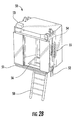
FIG. 2A shows a recovery car for use in a multicar elevator system, such as the system depicted inFIG. 1 ; -
FIG. 2B shows another view of the recovery car; -
FIG. 2C shows another view of the recovery car; and -
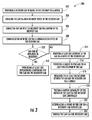
FIG. 3 shows a method for recovering a car within a multicar elevator system. -
FIG. 1 depicts a multicar,ropeless elevator system 10 in an illustrated embodiment.Elevator system 10 includes ahoistway 11 having a plurality oflanes elevator system 10 includes modular components that can be associated to form an elevator system. Modular components include, but are not limited to a landing floor hoistway, a shuttle floor hoistway, a transfer station, a carriage, a parking area, a disengaging mechanism, etc. While three lanes are shown inFIG. 1 , it is understood that embodiments may be used with multicar, ropeless elevator systems have any number of lanes. In eachlane cars 14 travel in mostly in one direction, i.e., up or down. For example, inFIG. 1 cars 14 inlanes cars 14 inlane 15 travel down. One ormore cars 14 may travel in asingle lane cars 14 can move bi-directionally withinlanes lanes lanes lanes hoistway 11 are assigned to various functions and building portions. In certain embodiments,cars 14 can circulate in a limited area ofhoistway 11. In certain embodiments,cars 14 can operate at a reduced velocity to reduce operating and equipment costs. In other embodiments,hoistways 11 andlanes hoistway 11 andlanes lanes - An
upper transfer station 30 to impart horizontal motion toelevator cars 14 to moveelevator cars 14 betweenlanes upper transfer station 30 andlower transfer station 32 in addition to other transfer stations can be disposed at any suitable location. It is understood thatupper transfer station 30 may be located at the top floor, rather than above the top floor. Below the first floor is alower transfer station 32 to impart horizontal motion toelevator cars 14 to moveelevator cars 14 betweenlanes lower transfer station 32 may be located at the first floor, rather than below the first floor.Cars 14 are propelled using, for example, a linear motor system having a primary, fixedportion 16 and a secondary, movingportion 18. One or more fixedportions 16 are mounted inlanes portions 18 are mounted oncars 14. One of the motor portions is supplied with drive signals to control movement ofcars 14 in their respective lanes. In certain embodiments, lanes ofhoistway 11 can be shut down or restricted based on operator input or elevator system conditions. - In the illustrated embodiment, the
elevator system 10 can include at least onerecovery car 50. Therecovery car 50 can be utilized to rescue or recover occupants from within immobilizedcars 14. During the course of operation, thecars 14 may experience mechanical malfunctions, electrical malfunctions, environmental conditions, or other conditions that cause thecars 14 to be immobilized or otherwise unsuitable for use while within thehoistway 11. Advantageously, therecovery car 50 can be utilized to remove occupants from thesecars 14, service thecars 14, or move thecars 14 to a service location within theelevator system 10. In certain embodiments, theelevator system 10 can includemultiple recovery cars 50 disposed at any suitable location. - Referring to
FIGS. 2A-2C , arecovery car 50 is shown. In the illustrated embodiment, therecovery car 50 includes anattachment point 52, amotor 54, and ahatch 56. In certain embodiments, therecovery car 50 can allow a technician within therecovery car 50 to control thecar 14 or allow remote operation of thecar 14. In certain embodiments, anysuitable car 14 can be designated or converted to be used as arecovery car 50. Further, in certain embodiments, therecovery car 50 can be utilized with localized directionality functions described herein. - In the illustrated embodiment, the
recovery car 50 includes anattachment point 52. In certain embodiments, thecars 14 can include asimilar attachment point 52 to allow therecovery car 50 to interface with thecar 14. In other embodiments, theattachment point 52 can attach to thecar 14 via any suitable feature. In the illustrated embodiment, theattachment point 52 attaches tocar 14 via friction. In certain embodiments, theattachment point 52 can utilize clips, or any other suitable attachment method to attach to thecar 14. In the illustrated embodiment, theattachment point 52 is suitable to tow thecar 14. Advantageously, the use of theattachment point 52 allows for therecovery car 50 to be coupled to thecar 14 for repair, occupant recovery, andcar 14 recovery operations. Theattachment point 52 can be disposed on an upper extent or a lower extent of therecovery car 50. - In order to dispose the
recovery car 50 adjacent to thecar 14, therecovery car 50 can include abuffer 51 to prevent damage in the event of contact between therecovery car 50 and thecar 14. Thebuffer 51 can be an elastomeric material, an inflatable material, or any other suitable construction to prevent damage in the event of contact. The use ofbuffer 51 can further reduce the noise of contact between thecar 14 and therecovery car 50. - In the illustrated embodiment, the
recovery car 50 includes amotor 54 to allow therecovery car 50 to travel within thehoistway 11. Themotor 54 can be any suitable motor, such as alinear motor 54 suitable for use within theelevator system 10. In certain embodiments, themotor 54 of therecovery car 50 is a morepowerful motor 54 compared to the motor of thecar 14 to enable therecovery car 50 to move heavier loads, such as a load required by arecovery car 50 carrying additional components, or to tow, push, or pull acar 14 that is immobilized. In certain embodiments, themotor 54 of therecovery car 50 is designed to move at a slower speed, while allowing for a higher load capability. In certain embodiments, thelinear motor 54 can communicate with a longer portion of a motor primary to allow for a higher load capability. - In certain embodiments, the
recovery car 50 can include abraking mechanism 55. In the illustrated embodiment, thebraking mechanism 55 may be larger than standard braking mechanisms ofcars 14 to support the braking demands of carrying additional components, or to tow, push, or pull acar 14 that is immobilized. - In the illustrated embodiment, the
recovery car 50 includes acontroller 53. In the illustrated embodiment, thecontroller 53 can control several operations of therecovery car 50 and an attachedcar 14. During a towing operation, wherein therecovery car 50 is attached to thecar 14, thecontroller 53 can utilize a wired connection or a wireless connection to communicate with thecar 14 to release the brakes of thecar 14 to initiate a towing procedure. In certain embodiments, the wired connection can be provided via the connection of theattachment point 52 to thecar 14. In the illustrated embodiment, thecontroller 53 can further evaluate themotor 54 performance to determine or test if themotor 54 has sufficient capacity to tow thecar 14. In certain embodiments, thecontroller 53 can analyze characteristics of the connectedcar 14 to determine a desired safety or motion profile, thecar 14 weight, and desiredmotor 54 performance. In certain embdoiments, acar 14 can be towed to another location within the elevator system. In certain embodiments, thecar 14 can removed from the active lanes of the elevator system. In other embodiments acar 14 can be replaced by a spare or replacement car while thecar 14 is serviced. - Further, in certain embodiments, the
controller 53 can receive diagnostic and service information from thecar 14. Similarly, this information can be provided via a wired connection or a wireless connection to thecar 14. In the illustrated embodiment, thecontroller 53 in conjunction with a wired or wireless connection tocar 14 can provide inter-car communication to occupants within thecar 14. In certain embodiments, thecontroller 53 can override the controls ofcar 14 to open and close the doors of thecar 14 as well as receive signals from on board video cameras to perform remote video inspection. In certain embodiments, thecontroller 53 can override and control any suitable parameter of thecar 14. In certain embodiments, therecovery car 50 can include a self-contained power source to energize therecovery car 50 and/or thecar 14. - In the illustrated embodiment, a
hatch 56 can allow technician access and occupant egress from thecar 14. Advantageously, thehatch 56 allows for access to thecar 14 if the doors of thecar 14 are not able to open. In the illustrated embodiment, thecar 14 includes a similar hatch to allow access out of thecar 14. In certain embodiments, thehatch 56 allows for occupants to exit thecar 14. In other embodiments, the technician can utilize thehatch 56 to perform inspection, replacement of components, and repairs upon thecar 14. In certain embodiments, replacement components are stored within therecovery car 50. In the illustrated embodiment, thehatch 56 allows for access to acar 14 below therecovery car 50. In other embodiments, thehatch 56 allows for access to acar 14 that is disposed above therecovery car 50. Thehatch 56 may be latched as necessary during travel. - To facilitate access between the
recovery car 50 and thecar 14, therecovery car 50 can include aladder 58. Theladder 58 can allow occupants to exit thecar 14 and enter therecovery car 50 and further allow technicians to enter thecar 14 from therecovery car 50. In certain embodiments, ashroud 59 can be deployed when thehatch 56 is open. The shroud can prevent the technician or occupants from being exposed to thehoistway 11, and further retains the technicians and occupants therein. Theshroud 59 may be permanently affixed to therecovery car 50 or can be deployed as needed. - Referring to
FIG. 3 a method to recover occupants and an elevator car within an elevator system is shown. Inoperation 302, a recovery car is provided to travel in the hoistway via a motor. In certain embodiments, the motor of the recovery car is a more powerful motor compared to the motor of the car to enable the recovery car to move heavier loads, such as a load required by a recovery car carrying additional components, or to tow, push, or pull a car that is immobilized. - In
operation 304, the car is engaged to the recovery car via an attachment device of the recovery car. In the illustrated embodiment, the attachment point attaches to car via friction. In certain embodiments, the attachment point can utilize clips, or any other suitable attachment method to attach to car. In the illustrated embodiment, the attachment point is suitable to tow car. - In
operation 306, the car contacts with the recovery car via a buffer of the recovery car. The buffer can be an elastomeric material, an inflatable material, or any other suitable construction to prevent damage in the event of contact. - In
operation 308, the car can communicate with the recovery car via a communication device of the recovery car. In the illustrated embodiment, the controller in conjunction with a wired or wireless connection to car can provide inter-car communication to occupants within the car. - In
operation 310, a technician can determine if the car can be repaired or if it necessary to move the car within the hoistway. If the car can be repaired,operation 312 can be performed. If the car must be moved,operation 314 can be performed. - If a repair is possible, in
operation 312, at least one replacement component for the car is provided via the recovery car. In certain scenarios, passengers may either remain within the car or be removed from the car depending on a technician's or other qualified personnel's safety assessment. - If it is desired to move the car, a technician or other qualified personnel may first assess the safety and risk of elevator occupants. In many scenarios, qualified personnel may determine that it is safer to keep occupants within an elevator car during recovery procedures. In other critical situations, qualified personnel may determine that occupants should be removed from the elevator car. In certain embodiments, critical sitautions can include elevator cars that cannot be towed or other dangerous situations.
- In
operation 310, at least one occupant of the car is removed via a hatch of the recovery car. Inoperation 312, a ladder is provided to the at least one occupant of the car. The ladder can allow occupants to exit the car and enter the recovery car. - In
operation 314, at least one occupant is retained between the car and the recovery car via a shroud. The shroud can prevent the technician or occupants from being exposed to the hoistway, and further retains the technicians and occupants therein. - If it is desired to move the car, in
operation 320, the motor capability of the motor of the car is tested via the recovery car controller. In the illustrated embodiment, the controller can evaluate the motor performance to determine or test if the motor has sufficient capacity to tow the car. - In
operation 322, a brake of the car is disengaged via a recovery car controller. During a towing operation, wherein the recovery car is attached to the car, the controller can utilize a wired connection or a wireless connection to communicate with the car to release the brakes of the car to initiate a towing procedure. - In
operation 324, the car is towed via the recovery car. The car can be towed to any suitable location, such as a predetermined service location within the elevator system. - The terminology used herein is for the purpose of describing particular embodiments only and is not intended to be limiting of the embodiments. While the description of the present embodiments has been presented for purposes of illustration and description, it is not intended to be exhaustive or limited to the embodiments in the form disclosed. Many modifications, variations, alterations, substitutions or equivalent arrangement not hereto described will be apparent to those of ordinary skill in the art without departing from the scope and spirit of the embodiments. Additionally, while various embodiments have been described, it is to be understood that aspects may include only some of the described embodiments. Accordingly, the embodiments are not to be seen as limited by the foregoing description, but are only limited by the scope of the appended claims.
Claims (15)
- A recovery car to recover a car in a hoistway of an elevator system, the recovery car comprising:a motor to transport the recovery car within the hoistway; andan attachment device to engage the car in the hoistway.
- The recovery car of claim 1, further comprising a buffer to contact the car.
- The recovery car of claim 1 or 2, further comprising a communication device to communicate with the car.
- The recovery car of claim 1, 2 or 3, further comprising a hatch to remove at least one occupant of the car.
- The recovery car of any preceding claim, further comprising a ladder to provide access to the car.
- The recovery car of any preceding claim, further comprising a shroud to retain the at least one occupant between the car and the recovery car.
- The recovery car of any preceding claim, wherein the recovery car tows the car via the attachment device.
- The recovery car of any preceding claim, wherein the recovery car is disposed above or below the car.
- The recovery car of any preceding claim, further comprising a recovery car controller to disengage a brake of the car.
- The recovery car of any preceding claim, wherein the recovery car controller tests a motor capability of the motor of the car.
- A method to recover a car in a hoistway of an elevator system comprising:providing a recovery car to travel in the hoistway via a motor; andengaging the car via an attachment device of the recovery car.
- The method of claim 11, further comprising contacting the car with the recovery car via a buffer of the recovery car.
- The method of claim 11 or 12, further comprising communicating with the car via a communication device of the recovery car.
- The method of claim 11, 12 or 13, further comprising removing at least one occupant of the car via a hatch of the recovery car.
- The method of any of claims 11-14, further comprising providing at least one replacement component for the car via the recovery car.
Applications Claiming Priority (1)
| Application Number | Priority Date | Filing Date | Title |
|---|---|---|---|
| US201562199543P | 2015-07-31 | 2015-07-31 |
Publications (1)
| Publication Number | Publication Date |
|---|---|
| EP3124419A1 true EP3124419A1 (en) | 2017-02-01 |
Family
ID=56561270
Family Applications (1)
| Application Number | Title | Priority Date | Filing Date |
|---|---|---|---|
| EP16182264.8A Withdrawn EP3124419A1 (en) | 2015-07-31 | 2016-08-01 | Elevator recovery car |
Country Status (3)
| Country | Link |
|---|---|
| US (1) | US10294074B2 (en) |
| EP (1) | EP3124419A1 (en) |
| CN (1) | CN106395568B (en) |
Cited By (1)
| Publication number | Priority date | Publication date | Assignee | Title |
|---|---|---|---|---|
| EP3964470A1 (en) | 2020-09-07 | 2022-03-09 | KONE Corporation | A multicar elevator system |
Families Citing this family (5)
| Publication number | Priority date | Publication date | Assignee | Title |
|---|---|---|---|---|
| EP2994406B1 (en) * | 2013-05-07 | 2018-01-10 | Otis Elevator Company | Connecting cars in a multicar elevator system |
| US20180237269A1 (en) * | 2017-02-17 | 2018-08-23 | Otis Elevator Company | Ropeless elevator system modular installation |
| EP3406556A1 (en) | 2017-05-23 | 2018-11-28 | Otis Elevator Company | Elevator doorway display systems for elevator cars |
| EP3632831B1 (en) * | 2018-10-03 | 2024-08-14 | KONE Corporation | Movable maintenance robot system, method for providing maintenance to an elevator car of an elevator and elevator |
| CN114436088A (en) * | 2020-11-02 | 2022-05-06 | 奥的斯电梯公司 | A safety exit subassembly and elevator system for elevator car |
Citations (4)
| Publication number | Priority date | Publication date | Assignee | Title |
|---|---|---|---|---|
| JPH03102085A (en) * | 1989-09-14 | 1991-04-26 | Mitsubishi Electric Corp | Emergency escape device for elevator |
| EP0499254A1 (en) * | 1991-02-14 | 1992-08-19 | Kabushiki Kaisha Toshiba | Self running type elevator system using linear motors |
| JPH05201642A (en) * | 1992-01-29 | 1993-08-10 | Mitsubishi Electric Corp | Ropeless linear motor elevator |
| WO2013076866A1 (en) * | 2011-11-25 | 2013-05-30 | 三菱電機株式会社 | Elevator system |
Family Cites Families (27)
| Publication number | Priority date | Publication date | Assignee | Title |
|---|---|---|---|---|
| US627257A (en) * | 1899-06-20 | Elevator-cage escape | ||
| US837826A (en) * | 1906-07-02 | 1906-12-04 | Alexander H Handlan Jr | Elevator. |
| US4511017A (en) | 1983-09-20 | 1985-04-16 | Westinghouse Electric Corp. | Elevator system |
| EP0586190A1 (en) | 1992-08-31 | 1994-03-09 | Otis Elevator Company | Rescue operation for an elevator system |
| FI111934B (en) * | 1992-12-22 | 2003-10-15 | Kone Corp | Remote control system in elevator devices |
| JP3324179B2 (en) | 1993-03-10 | 2002-09-17 | 三菱電機株式会社 | Low-press elevator equipment |
| US5816368A (en) | 1997-03-20 | 1998-10-06 | Otis Elevator Company | Elevator cars switch hoistways while traveling vertically |
| US6196355B1 (en) * | 1999-03-26 | 2001-03-06 | Otis Elevator Company | Elevator rescue system |
| JP2000344447A (en) * | 1999-05-07 | 2000-12-12 | Inventio Ag | Device for performing operation within elevator shaft |
| JP2001171932A (en) | 1999-12-17 | 2001-06-26 | Hitachi Building Systems Co Ltd | Elevator rescue device |
| ES2208293T3 (en) * | 2000-04-20 | 2004-06-16 | Inventio Ag | DEVICE FOR THE EXECUTION OF WORK IN AN ELEVATOR BOX. |
| US6364066B1 (en) * | 2000-04-24 | 2002-04-02 | Otis Elevator Company | Remote rescue of trapped elevator passengers |
| JP2004002020A (en) * | 2002-05-27 | 2004-01-08 | Inventio Ag | Elevator facility provided with several self-travelling cars and at least three adjacently arranged elevator hoistways |
| US20050224299A1 (en) * | 2004-04-13 | 2005-10-13 | Soemardjan San A | Elevator recessed car top for refuge area |
| WO2006009542A1 (en) | 2004-06-21 | 2006-01-26 | Otis Elevator Company | Elevator system including multiple cars in a hoistway |
| JP4543868B2 (en) | 2004-10-15 | 2010-09-15 | 株式会社日立製作所 | Multi car elevator |
| CN100584724C (en) | 2004-12-16 | 2010-01-27 | 奥蒂斯电梯公司 | Elevator system having multiple cars in hoistway |
| WO2007091292A1 (en) * | 2006-02-06 | 2007-08-16 | Mitsubishi Denki Kabushiki Kaisha | Elevator car rescue device |
| JPWO2007125595A1 (en) * | 2006-04-28 | 2009-09-10 | 三菱電機株式会社 | Elevator equipment |
| EP1935829A1 (en) | 2006-12-21 | 2008-06-25 | Inventio Ag | Elevator comprising two elevator cars in a shaft |
| JP4539682B2 (en) | 2007-06-12 | 2010-09-08 | 株式会社日立製作所 | Multi car elevator |
| JP5224933B2 (en) * | 2008-06-25 | 2013-07-03 | 株式会社日立製作所 | Elevator restoration operation method and apparatus |
| US20120006626A1 (en) | 2009-04-29 | 2012-01-12 | Otis Elevator Company | Elevator system including multiple cars within a single hoistway |
| US8430210B2 (en) | 2011-01-19 | 2013-04-30 | Smart Lifts, Llc | System having multiple cabs in an elevator shaft |
| EP2766290A4 (en) * | 2011-10-14 | 2015-06-24 | Otis Elevator Co | Elevator system with messaging for automated maintenance |
| US10118799B2 (en) | 2013-03-25 | 2018-11-06 | Otis Elevator Company | Multicar self-propelled elevator system |
| IT201700020206A1 (en) | 2017-02-22 | 2018-08-22 | New Optic Italia S R L | FRAME FOR GLASSES IN TWO PIECES WITH LOCKING DEVICE FOR A PAIR OF LENSES |
-
2016
- 2016-07-29 CN CN201610619446.1A patent/CN106395568B/en active Active
- 2016-08-01 EP EP16182264.8A patent/EP3124419A1/en not_active Withdrawn
- 2016-08-01 US US15/225,325 patent/US10294074B2/en active Active
Patent Citations (4)
| Publication number | Priority date | Publication date | Assignee | Title |
|---|---|---|---|---|
| JPH03102085A (en) * | 1989-09-14 | 1991-04-26 | Mitsubishi Electric Corp | Emergency escape device for elevator |
| EP0499254A1 (en) * | 1991-02-14 | 1992-08-19 | Kabushiki Kaisha Toshiba | Self running type elevator system using linear motors |
| JPH05201642A (en) * | 1992-01-29 | 1993-08-10 | Mitsubishi Electric Corp | Ropeless linear motor elevator |
| WO2013076866A1 (en) * | 2011-11-25 | 2013-05-30 | 三菱電機株式会社 | Elevator system |
Cited By (1)
| Publication number | Priority date | Publication date | Assignee | Title |
|---|---|---|---|---|
| EP3964470A1 (en) | 2020-09-07 | 2022-03-09 | KONE Corporation | A multicar elevator system |
Also Published As
| Publication number | Publication date |
|---|---|
| CN106395568B (en) | 2020-05-05 |
| US10294074B2 (en) | 2019-05-21 |
| US20170029245A1 (en) | 2017-02-02 |
| CN106395568A (en) | 2017-02-15 |
Similar Documents
| Publication | Publication Date | Title |
|---|---|---|
| US10294074B2 (en) | Elevator recovery car | |
| US10865072B2 (en) | Intermediate transfer station | |
| US9016438B2 (en) | Carrying device for relocating a car of an elevator | |
| CN107108150B (en) | Configurable multi-car elevator system | |
| EP3436384B1 (en) | Method for operating a lift system and lift system designed for carrying out the method | |
| EP3489184A1 (en) | Hoistway inspection device | |
| CN106553948B (en) | Braking system for a hoisted structure and method of controlling braking of a hoisted structure | |
| CN107434196B (en) | Electronic safety device with power assembly | |
| US20210147183A1 (en) | Elevator system | |
| CN112955397A (en) | Elevator installation and method for operating an elevator installation with an auxiliary device | |
| JP2016044078A (en) | Elevator door closing method and mechanism | |
| CN109798005A (en) | Transportation system and method for haulage vehicle | |
| CN106477416B (en) | Method for moving an elevator car and elevator | |
| CN116081413B (en) | System for monitoring hall activity to determine whether to cancel elevator service | |
| US20170355562A1 (en) | Fire service sequence for multicar elevator systems | |
| CN107207195A (en) | Component for activating elevator car brake | |
| US20170240380A1 (en) | Evacuation concept for elevator systems | |
| WO2018054927A1 (en) | Elevator system having a car comprising a catching device | |
| KR102464079B1 (en) | Transportation system for building and method for controlling the same | |
| US11542123B2 (en) | Elevator system including a motorized module | |
| JP2018193138A (en) | Elevator monitoring device and elevator monitoring method | |
| DE112017004022T5 (en) | LIFT SYSTEM | |
| JPH03102085A (en) | Emergency escape device for elevator | |
| CN122055315A (en) | Elevator safety controller, elevator system and method for emergency stopping elevator car | |
| CN114314229A (en) | Elevator system and method for operating an elevator system |
Legal Events
| Date | Code | Title | Description |
|---|---|---|---|
| PUAI | Public reference made under article 153(3) epc to a published international application that has entered the european phase |
Free format text: ORIGINAL CODE: 0009012 |
|
| STAA | Information on the status of an ep patent application or granted ep patent |
Free format text: STATUS: THE APPLICATION HAS BEEN PUBLISHED |
|
| AK | Designated contracting states |
Kind code of ref document: A1 Designated state(s): AL AT BE BG CH CY CZ DE DK EE ES FI FR GB GR HR HU IE IS IT LI LT LU LV MC MK MT NL NO PL PT RO RS SE SI SK SM TR |
|
| AX | Request for extension of the european patent |
Extension state: BA ME |
|
| STAA | Information on the status of an ep patent application or granted ep patent |
Free format text: STATUS: REQUEST FOR EXAMINATION WAS MADE |
|
| 17P | Request for examination filed |
Effective date: 20170801 |
|
| RAP1 | Party data changed (applicant data changed or rights of an application transferred) |
Owner name: OTIS ELEVATOR COMPANY |
|
| RBV | Designated contracting states (corrected) |
Designated state(s): AL AT BE BG CH CY CZ DE DK EE ES FI FR GB GR HR HU IE IS IT LI LT LU LV MC MK MT NL NO PL PT RO RS SE SI SK SM TR |
|
| STAA | Information on the status of an ep patent application or granted ep patent |
Free format text: STATUS: THE APPLICATION IS DEEMED TO BE WITHDRAWN |
|
| 18D | Application deemed to be withdrawn |
Effective date: 20200303 |