EP3124339A1 - Device for washing of vehicles in self-service facilities - Google Patents
Device for washing of vehicles in self-service facilities Download PDFInfo
- Publication number
- EP3124339A1 EP3124339A1 EP16176861.9A EP16176861A EP3124339A1 EP 3124339 A1 EP3124339 A1 EP 3124339A1 EP 16176861 A EP16176861 A EP 16176861A EP 3124339 A1 EP3124339 A1 EP 3124339A1
- Authority
- EP
- European Patent Office
- Prior art keywords
- boom
- section
- rail
- self
- flexible hose
- Prior art date
- Legal status (The legal status is an assumption and is not a legal conclusion. Google has not performed a legal analysis and makes no representation as to the accuracy of the status listed.)
- Withdrawn
Links
- 238000005406 washing Methods 0.000 title claims abstract description 20
- 238000004140 cleaning Methods 0.000 claims abstract description 8
- 239000007788 liquid Substances 0.000 description 2
- XLYOFNOQVPJJNP-UHFFFAOYSA-N water Substances O XLYOFNOQVPJJNP-UHFFFAOYSA-N 0.000 description 2
- 238000005452 bending Methods 0.000 description 1
- 230000008878 coupling Effects 0.000 description 1
- 238000010168 coupling process Methods 0.000 description 1
- 238000005859 coupling reaction Methods 0.000 description 1
- 238000005516 engineering process Methods 0.000 description 1
- 230000002452 interceptive effect Effects 0.000 description 1
Images
Classifications
-
- B—PERFORMING OPERATIONS; TRANSPORTING
- B60—VEHICLES IN GENERAL
- B60S—SERVICING, CLEANING, REPAIRING, SUPPORTING, LIFTING, OR MANOEUVRING OF VEHICLES, NOT OTHERWISE PROVIDED FOR
- B60S3/00—Vehicle cleaning apparatus not integral with vehicles
- B60S3/04—Vehicle cleaning apparatus not integral with vehicles for exteriors of land vehicles
- B60S3/044—Hand-held cleaning arrangements with liquid or gas distributing means
Definitions
- This invention refers to a device applicable to vehicle washing facilities, the purpose of which is to allow the use of washing elements, such as pressure guns, brushes and other elements connected to the end of a hose.
- the device is installed through the ceiling of the facility or, at least, through an area above the vehicle to be washed, facilitating the movement or rotation thereof without interfering with each other when at least two of these devices are used or installed.
- These devices are known in the language of the sector as booms.
- One of the principal objectives of the technology used in self-service vehicle washing facilities is to prevent the hose with pressure guns from becoming tangled with each other or blocked when used.
- devices formed by a rail are used; these are positioned on a higher level than the vehicle, normally in the ceiling of the facility. Attached to this rail by means of a joint is a rotating arm, which is known as a boom in the sector.
- the boom is connected on the joint side to a hydraulic connection which supplies water.
- the other end is connected to a flexible hose incorporating the pressure gun for washing the vehicle, a brush or any other cleaning element.
- the boom can rotate and even move along the rail to access the different sides of the vehicle.
- the booms which exist in the current state of the art are formed of several parts with special shapes, through which the liquid conduit passes.
- a variety of connections is used as far as the upper joint fixing the boom, where a connection with the fixed conduit of the facility is established again.
- Document ES-1045290_U is an example of one of these facilities.
- This document describes a device for self-service vehicle washing facilities formed of a rail, which serves as support for the coupling of rotating arms or booms by means of a joint which, in addition to allowing the booms to rotate, also allows them to move along the rail.
- the rail is located in the upper part of the facility, crosswise to the position of the vehicle.
- a hydraulic connection supplies water to the boom entrance in the area of each joint.
- a flexible hose or tube is coupled, which ends in a pressure gun for washing of the vehicle.
- This invention describes a device that prevents the aforementioned problem by incorporating a single flexible hose which removes the need for all kinds of connections from the end to the fixed conduit of the facility.
- This invention describes a device for washing of vehicles in self-service facilities.
- the device comprises a boom with a rigid section connected to a rail by means of an element which can move along the rail.
- This element can be a rotating joint or a shaft in a crosswise position to the rail that comprises rotating joints at its ends.
- the rigid section of the boom comprises a straight section, a curved section and a flexible section, which connects the straight section with the curved section and is sloping with regard to the horizontal, so that if there is more than one boom, they do not interfere with each other.
- the invention presents a continuous flexible hose, which runs along the whole boom in such a way that one end of the flexible hose extends from the free end of the straight section to connect to a fixed hydraulic conduit in the facility by means of a joint, and the other end of the flexible hose extends from the free end of the curved section of the boom to connect to a cleaning element which may be, for example, a pressure gun, a lance or a brush.
- a cleaning element which may be, for example, a pressure gun, a lance or a brush.
- the free end of the curved section is bellmouthed, to prevent rubbing which might jeopardise the useful life of the flexible hose.
- This invention refers to a device for washing of vehicles in self-service facilities.
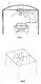
- Figure 1 represents a washing facility comprising a tunnel which incorporates in the ceiling a rail (8) along which two booms (1) move. Although it has not been represented in this embodiment, the facility may comprise just one boom (1) without affecting the invention.
- the rail (8) is positioned crosswise to the direction in which the vehicle moves.
- Each of the booms (1) is fixed to the rail (8) by means of a rotating joint (5) which allows the end of the boom (1), which is where the cleaning element is located, to reach any part of the vehicle being washed.
- Figure 2 represents a second embodiment in which one of the joints (5) is replaced by a shaft (9) positioned crosswise to the rail (8).
- the shaft (9) incorporates a joint (5) at each of its ends, by means of which a boom (1) is fixed.
- this embodiment incorporates a device with three booms (1).
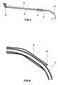
- FIG. 3 represents in detail a boom (1) of the device in this invention. It may be observed that the boom (1) comprises a straight section (2), a curved section (3) and a flexible section (4) which connects the straight section (2) to the curved section (3).
- a flexible hose (7) is positioned inside the different sections (2, 3, 4) of the boom (1), emerging from both ends.
- the flexible section (4) is a section with a spiral configuration that leaves free an internal diameter of sufficient dimensions to house the flexible hose (7). This flexible section (4) makes the boom (1) more agile, allowing the curved section to rotate independently of the straight section (2).
- the free end of the straight section (2) of the boom (1) is attached to a rotating joint (5).
- the joint (5) is fixed on a rail (8) along which it can move.
- the flexible hose (7) is attached to the fixed hydraulic conduit of the facility.
- the curved section (3) ends in a mouth (6) through which the flexible hose emerges (7).
- This detail is represented more clearly in figure 4 .
- the mouth (6) at the end is bellmouthed. This ensures that, when the boom (1) rotates, the flexible hose (7) suffers less when bending.
- the washing element is installed, normally a pressure gun, but it may also be a brush, a lance or any other component for cleaning the vehicle.
- the use of two booms (1) in the same facility means that the straight sections (2) of the booms (1) are rotated at a downward angle to the horizontal. This angle is sufficiently large to ensure that a boom (1) does not interfere with a second boom (1) and sufficiently small not to interfere with vehicles which are higher than normal.
- the fixed hydraulic conduit in the facility incorporates a means to absorb the necessary increase in length caused by the movement of the booms (1) along the rail (8). Normally this is achieved by incorporating in the fixed conduit of the facility a rolled flexible hose that incorporates an automatic retraction system such as, for example, a mechanism with a spring.
Landscapes
- Engineering & Computer Science (AREA)
- Mechanical Engineering (AREA)
- Cleaning In General (AREA)
- Vehicle Cleaning, Maintenance, Repair, Refitting, And Outriggers (AREA)
Abstract
Device for washing of vehicles in self-service facilities, which comprises a boom (1) with a rigid section attached to a rail (8) by means of an element which moves along the rail (8). The rigid section is formed of a straight section (2), an intermediate flexible section (4) and a curved section (3). A continuous flexible hose (7) runs along all the sections (2, 3, 4) of the boom (1) such that one end of the flexible hose (7) extends from the free end of the straight section (2) to connect to a fixed hydraulic conduit in the facilities by means of a joint (5), and the other end of the flexible hose (7) extends from the free end of the curved section (3) of the boom (1) to connect to a cleaning element.
Description
- This invention refers to a device applicable to vehicle washing facilities, the purpose of which is to allow the use of washing elements, such as pressure guns, brushes and other elements connected to the end of a hose. The device is installed through the ceiling of the facility or, at least, through an area above the vehicle to be washed, facilitating the movement or rotation thereof without interfering with each other when at least two of these devices are used or installed. These devices are known in the language of the sector as booms.
- One of the principal objectives of the technology used in self-service vehicle washing facilities is to prevent the hose with pressure guns from becoming tangled with each other or blocked when used. To prevent this, devices formed by a rail are used; these are positioned on a higher level than the vehicle, normally in the ceiling of the facility. Attached to this rail by means of a joint is a rotating arm, which is known as a boom in the sector. The boom is connected on the joint side to a hydraulic connection which supplies water. The other end is connected to a flexible hose incorporating the pressure gun for washing the vehicle, a brush or any other cleaning element. The boom can rotate and even move along the rail to access the different sides of the vehicle.
- The booms which exist in the current state of the art are formed of several parts with special shapes, through which the liquid conduit passes. For this purpose, a variety of connections is used as far as the upper joint fixing the boom, where a connection with the fixed conduit of the facility is established again.
- Document
ES-1045290_U - However, there is a recurring problem with these devices, which is the need to include various connecting areas that may cause leaks of liquid, as well as being critical points, which jeopardise the smooth operation when the vehicle is being washed.
- This invention describes a device that prevents the aforementioned problem by incorporating a single flexible hose which removes the need for all kinds of connections from the end to the fixed conduit of the facility.
- This invention describes a device for washing of vehicles in self-service facilities. The device comprises a boom with a rigid section connected to a rail by means of an element which can move along the rail. This element can be a rotating joint or a shaft in a crosswise position to the rail that comprises rotating joints at its ends.
- The rigid section of the boom comprises a straight section, a curved section and a flexible section, which connects the straight section with the curved section and is sloping with regard to the horizontal, so that if there is more than one boom, they do not interfere with each other.
- The invention presents a continuous flexible hose, which runs along the whole boom in such a way that one end of the flexible hose extends from the free end of the straight section to connect to a fixed hydraulic conduit in the facility by means of a joint, and the other end of the flexible hose extends from the free end of the curved section of the boom to connect to a cleaning element which may be, for example, a pressure gun, a lance or a brush.
- To ensure better performance of the flexible hose, the free end of the curved section is bellmouthed, to prevent rubbing which might jeopardise the useful life of the flexible hose.
- To complete the invention being described, and in order to help with better understanding of the characteristics of the invention, according to a preferred embodiment thereof, it is accompanied by a set of drawings in which the figures described below have been represented, for purely illustrative purposes and should not be construed as limiting:
-
Figure 1 represents a rear view of the washing facility. -
Figure 2 represents a facility incorporating three booms. -
Figure 3 represents a side view of a complete boom. -
Figure 4 represents an enlarged view of the mouth of the boom through which the flexible hose emerges to be attached to a cleaning element. - Provided below is a list of the references used in the figures:
- 1. Boom
- 2. Straight section of the boom.
- 3. Curved section of the boom.
- 4. Flexible section of the boom.
- 5. Joint.
- 6. End mouth of the boom.
- 7. Flexible hose.
- 8. Rail.
- 9. Shaft.
- This invention refers to a device for washing of vehicles in self-service facilities.
-
Figure 1 represents a washing facility comprising a tunnel which incorporates in the ceiling a rail (8) along which two booms (1) move. Although it has not been represented in this embodiment, the facility may comprise just one boom (1) without affecting the invention. The rail (8) is positioned crosswise to the direction in which the vehicle moves. Each of the booms (1) is fixed to the rail (8) by means of a rotating joint (5) which allows the end of the boom (1), which is where the cleaning element is located, to reach any part of the vehicle being washed. -
Figure 2 represents a second embodiment in which one of the joints (5) is replaced by a shaft (9) positioned crosswise to the rail (8). The shaft (9) incorporates a joint (5) at each of its ends, by means of which a boom (1) is fixed. Thus, this embodiment incorporates a device with three booms (1). -
Figure 3 represents in detail a boom (1) of the device in this invention. It may be observed that the boom (1) comprises a straight section (2), a curved section (3) and a flexible section (4) which connects the straight section (2) to the curved section (3). A flexible hose (7) is positioned inside the different sections (2, 3, 4) of the boom (1), emerging from both ends. The flexible section (4) is a section with a spiral configuration that leaves free an internal diameter of sufficient dimensions to house the flexible hose (7). This flexible section (4) makes the boom (1) more agile, allowing the curved section to rotate independently of the straight section (2). - The free end of the straight section (2) of the boom (1) is attached to a rotating joint (5). The joint (5) is fixed on a rail (8) along which it can move. At this end of the boom (1), the flexible hose (7) is attached to the fixed hydraulic conduit of the facility.
- At the other end of the boom (1), the curved section (3) ends in a mouth (6) through which the flexible hose emerges (7). This detail is represented more clearly in
figure 4 . Because of the continuous movements experienced by the boom (1) during a washing process, the mouth (6) at the end is bellmouthed. This ensures that, when the boom (1) rotates, the flexible hose (7) suffers less when bending. At this end of the flexible hose (7), the washing element is installed, normally a pressure gun, but it may also be a brush, a lance or any other component for cleaning the vehicle. - The use of two booms (1) in the same facility means that the straight sections (2) of the booms (1) are rotated at a downward angle to the horizontal. This angle is sufficiently large to ensure that a boom (1) does not interfere with a second boom (1) and sufficiently small not to interfere with vehicles which are higher than normal.
- The fixed hydraulic conduit in the facility incorporates a means to absorb the necessary increase in length caused by the movement of the booms (1) along the rail (8). Normally this is achieved by incorporating in the fixed conduit of the facility a rolled flexible hose that incorporates an automatic retraction system such as, for example, a mechanism with a spring.
- The present invention is not limited by the embodiment disclosed herein. Other embodiments may be carried out by persons skilled in the art in light of this description. In consequence, the scope of the invention is defined by the following claims.
Claims (6)
- Device for washing vehicles in self-service facilities which comprises a boom (1) with a rigid section attached to a rail (8) by means of an element which can move along the rail (8), in which said device is characterised in that the rigid section of the boom (1) comprises:- a straight section (2),- a flexible section (4) attached, at one of its ends, to the straight section (2),- a curved section (3) attached, at one of its ends, to the free end of the flexible section (4),wherein a continuous flexible hose (7) runs along all the sections (2, 3, 4) of the boom (1), in such a way that:- one end of the flexible hose (7) emerges from the free end of the straight section (2) to connect to a fixed hydraulic conduit in the facility by means of the joint (5), and- the other end of the flexible hose (7) emerges from the free end of the curved section (3) of the boom (1) to connect to a cleaning element.
- Device for washing vehicles in self-service facilities, according to claim 1, characterised in that the element which can move along the rail (8) is a rotating joint (5).
- Device for washing vehicles in self-service facilities, according to claim 1, characterised in that the element which can move along the rail (8) is a shaft (9) positioned crosswise to the rail (8) which comprises rotating joints (5) at its ends.
- Device for washing vehicles in self-service facilities, according to any of the claims 1 to 3, characterised in that the end of the curved section (3) is bellmouthed.
- Device for washing vehicles in self-service facilities, according to any of the previous claims, characterised in that the straight section (2) of the boom (1) is inclined with regard to the horizontal.
- Device for washing vehicles in self-service facilities, according to any of the previous claims, characterised in that the cleaning element is to be selected among a pressure gun, a lance and a brush.
Applications Claiming Priority (1)
| Application Number | Priority Date | Filing Date | Title |
|---|---|---|---|
| ES201530904U ES1142609Y (en) | 2015-07-31 | 2015-07-31 | DEVICE FOR WASHING VEHICLES IN SELF-SERVICE FACILITIES |
Publications (1)
| Publication Number | Publication Date |
|---|---|
| EP3124339A1 true EP3124339A1 (en) | 2017-02-01 |
Family
ID=53871671
Family Applications (1)
| Application Number | Title | Priority Date | Filing Date |
|---|---|---|---|
| EP16176861.9A Withdrawn EP3124339A1 (en) | 2015-07-31 | 2016-06-29 | Device for washing of vehicles in self-service facilities |
Country Status (2)
| Country | Link |
|---|---|
| EP (1) | EP3124339A1 (en) |
| ES (1) | ES1142609Y (en) |
Citations (4)
| Publication number | Priority date | Publication date | Assignee | Title |
|---|---|---|---|---|
| FR2754746A3 (en) * | 1996-10-17 | 1998-04-24 | Mosmatic Ag | ROTARY CEILING ELEMENT FOR SELF-SERVICE WASHING FACILITIES |
| ES1045290U (en) | 2000-01-20 | 2000-08-16 | Istobal Sa | Device and swivel arms for hanging washing facilities self-service motor vehicles. (Machine-translation by Google Translate, not legally binding) |
| DE29623972U1 (en) * | 1996-04-13 | 2000-11-23 | Wap Reinigungssysteme Gmbh & Co, 89287 Bellenberg | Folding swivel gyro for self-service car washes |
| DE202012101872U1 (en) * | 2012-05-22 | 2012-07-02 | Syntecs Gmbh Reinigungssysteme | Ceiling gyro of a cleaning plant |
-
2015
- 2015-07-31 ES ES201530904U patent/ES1142609Y/en not_active Expired - Fee Related
-
2016
- 2016-06-29 EP EP16176861.9A patent/EP3124339A1/en not_active Withdrawn
Patent Citations (4)
| Publication number | Priority date | Publication date | Assignee | Title |
|---|---|---|---|---|
| DE29623972U1 (en) * | 1996-04-13 | 2000-11-23 | Wap Reinigungssysteme Gmbh & Co, 89287 Bellenberg | Folding swivel gyro for self-service car washes |
| FR2754746A3 (en) * | 1996-10-17 | 1998-04-24 | Mosmatic Ag | ROTARY CEILING ELEMENT FOR SELF-SERVICE WASHING FACILITIES |
| ES1045290U (en) | 2000-01-20 | 2000-08-16 | Istobal Sa | Device and swivel arms for hanging washing facilities self-service motor vehicles. (Machine-translation by Google Translate, not legally binding) |
| DE202012101872U1 (en) * | 2012-05-22 | 2012-07-02 | Syntecs Gmbh Reinigungssysteme | Ceiling gyro of a cleaning plant |
Also Published As
| Publication number | Publication date |
|---|---|
| ES1142609Y (en) | 2015-11-18 |
| ES1142609U (en) | 2015-08-24 |
Similar Documents
| Publication | Publication Date | Title |
|---|---|---|
| RU2435696C2 (en) | Device for end connection of deformable pipeline intended for fluid transportation to immobile pipeline such as ship header pipe | |
| RU2455224C2 (en) | System to transfer natural liquefied gas from inshore tanker to floating or stationary storage | |
| CN102460871B (en) | A guidance chain for guiding cables or other lines in a medical diagnostic apparatus | |
| CA2760097C (en) | Apparatus for insertion in a tank and method thereof | |
| CN102333622B (en) | Robot, particularly spray robot | |
| CN106077001A (en) | A kind of product oil internal floating roof tank cleaning robot | |
| WO2020010142A1 (en) | Systems and methods for cleaning and maintenance of tanks | |
| EP2287988B1 (en) | Article conveying robot device | |
| WO2010061341A2 (en) | Device for routing wire | |
| EP3124339A1 (en) | Device for washing of vehicles in self-service facilities | |
| US9616858B2 (en) | Jointed car wash gravity hose boom | |
| EP2716369A1 (en) | Misting apparatus and sprinkling device thereof | |
| SE1850702A1 (en) | Support arm arrangement for a local gas extractor, and a local gas extractor with such a support arm arrangement | |
| CN104922839A (en) | Hydraulic arm structure mounted in high-rise buildings | |
| CN114738594B (en) | Pipeline Robots and Systems | |
| CN213588222U (en) | Controllable angle detection device of endoscope | |
| KR101690596B1 (en) | Boom system of cleaning device for vehicle | |
| RU2668116C1 (en) | Cutter-loader cable layer holder | |
| JP2690934B2 (en) | Endoscope | |
| CN212947895U (en) | Plant is with equipment of decontaminating | |
| JP7213748B2 (en) | slide boom | |
| CN209241081U (en) | A kind of dedicated armed lever and loading water structure of train water robot | |
| KR200422266Y1 (en) | Piping device for fluid transfer using flexible piping structure | |
| SU1076031A1 (en) | Apparatus for intake and supply of water to sprinklers on movement | |
| DE102023116834B3 (en) | Device for sewer pipe inspection and/or renovation of a connecting pipe branching off from a main sewer |
Legal Events
| Date | Code | Title | Description |
|---|---|---|---|
| PUAI | Public reference made under article 153(3) epc to a published international application that has entered the european phase |
Free format text: ORIGINAL CODE: 0009012 |
|
| AK | Designated contracting states |
Kind code of ref document: A1 Designated state(s): AL AT BE BG CH CY CZ DE DK EE ES FI FR GB GR HR HU IE IS IT LI LT LU LV MC MK MT NL NO PL PT RO RS SE SI SK SM TR |
|
| AX | Request for extension of the european patent |
Extension state: BA ME |
|
| STAA | Information on the status of an ep patent application or granted ep patent |
Free format text: STATUS: THE APPLICATION IS DEEMED TO BE WITHDRAWN |
|
| 18D | Application deemed to be withdrawn |
Effective date: 20170802 |