EP3124092A1 - Filter for hydraulic fluids for hydraulic circuits and process of making the same - Google Patents
Filter for hydraulic fluids for hydraulic circuits and process of making the same Download PDFInfo
- Publication number
- EP3124092A1 EP3124092A1 EP16181725.9A EP16181725A EP3124092A1 EP 3124092 A1 EP3124092 A1 EP 3124092A1 EP 16181725 A EP16181725 A EP 16181725A EP 3124092 A1 EP3124092 A1 EP 3124092A1
- Authority
- EP
- European Patent Office
- Prior art keywords
- container
- cartridge
- filtering cartridge
- collar
- coupling surface
- Prior art date
- Legal status (The legal status is an assumption and is not a legal conclusion. Google has not performed a legal analysis and makes no representation as to the accuracy of the status listed.)
- Granted
Links
- 239000012530 fluid Substances 0.000 title claims abstract description 63
- 238000000034 method Methods 0.000 title claims description 27
- 238000001914 filtration Methods 0.000 claims abstract description 189
- 230000008878 coupling Effects 0.000 claims abstract description 164
- 238000010168 coupling process Methods 0.000 claims abstract description 164
- 238000005859 coupling reaction Methods 0.000 claims abstract description 164
- 230000001747 exhibiting effect Effects 0.000 claims abstract description 53
- 238000000638 solvent extraction Methods 0.000 claims abstract description 3
- 238000011161 development Methods 0.000 claims description 49
- 230000000903 blocking effect Effects 0.000 claims description 48
- 239000012528 membrane Substances 0.000 claims description 26
- 239000000463 material Substances 0.000 description 37
- 239000004033 plastic Substances 0.000 description 30
- 239000004677 Nylon Substances 0.000 description 19
- 229920001778 nylon Polymers 0.000 description 19
- 239000007769 metal material Substances 0.000 description 16
- 229910052782 aluminium Inorganic materials 0.000 description 15
- XAGFODPZIPBFFR-UHFFFAOYSA-N aluminium Chemical compound [Al] XAGFODPZIPBFFR-UHFFFAOYSA-N 0.000 description 15
- 229910000831 Steel Inorganic materials 0.000 description 12
- 239000010959 steel Substances 0.000 description 12
- 238000000465 moulding Methods 0.000 description 11
- 229910001018 Cast iron Inorganic materials 0.000 description 8
- 239000000356 contaminant Substances 0.000 description 5
- 230000002441 reversible effect Effects 0.000 description 4
- 238000007789 sealing Methods 0.000 description 4
- 238000006073 displacement reaction Methods 0.000 description 3
- 239000013536 elastomeric material Substances 0.000 description 3
- 239000007789 gas Substances 0.000 description 3
- 238000004519 manufacturing process Methods 0.000 description 3
- 239000007787 solid Substances 0.000 description 3
- 238000004026 adhesive bonding Methods 0.000 description 2
- 238000010276 construction Methods 0.000 description 2
- 230000007797 corrosion Effects 0.000 description 2
- 238000005260 corrosion Methods 0.000 description 2
- 238000001125 extrusion Methods 0.000 description 2
- 239000007788 liquid Substances 0.000 description 2
- 238000005461 lubrication Methods 0.000 description 2
- 238000002844 melting Methods 0.000 description 2
- 230000008018 melting Effects 0.000 description 2
- 229910052751 metal Inorganic materials 0.000 description 2
- 239000002184 metal Substances 0.000 description 2
- 238000003860 storage Methods 0.000 description 2
- 239000000126 substance Substances 0.000 description 2
- 238000003490 calendering Methods 0.000 description 1
- 238000004891 communication Methods 0.000 description 1
- 230000006835 compression Effects 0.000 description 1
- 238000007906 compression Methods 0.000 description 1
- 230000001010 compromised effect Effects 0.000 description 1
- 238000013461 design Methods 0.000 description 1
- 238000007599 discharging Methods 0.000 description 1
- 238000005265 energy consumption Methods 0.000 description 1
- 230000008595 infiltration Effects 0.000 description 1
- 238000001764 infiltration Methods 0.000 description 1
- 238000003780 insertion Methods 0.000 description 1
- 230000037431 insertion Effects 0.000 description 1
- 230000001050 lubricating effect Effects 0.000 description 1
- 239000002245 particle Substances 0.000 description 1
- 238000005192 partition Methods 0.000 description 1
- 239000002699 waste material Substances 0.000 description 1
- XLYOFNOQVPJJNP-UHFFFAOYSA-N water Substances O XLYOFNOQVPJJNP-UHFFFAOYSA-N 0.000 description 1
- 238000003466 welding Methods 0.000 description 1
Images


Classifications
-
- B—PERFORMING OPERATIONS; TRANSPORTING
- B01—PHYSICAL OR CHEMICAL PROCESSES OR APPARATUS IN GENERAL
- B01D—SEPARATION
- B01D35/00—Filtering devices having features not specifically covered by groups B01D24/00 - B01D33/00, or for applications not specifically covered by groups B01D24/00 - B01D33/00; Auxiliary devices for filtration; Filter housing constructions
- B01D35/30—Filter housing constructions
- B01D35/306—Filter mounting adapter
-
- F—MECHANICAL ENGINEERING; LIGHTING; HEATING; WEAPONS; BLASTING
- F15—FLUID-PRESSURE ACTUATORS; HYDRAULICS OR PNEUMATICS IN GENERAL
- F15B—SYSTEMS ACTING BY MEANS OF FLUIDS IN GENERAL; FLUID-PRESSURE ACTUATORS, e.g. SERVOMOTORS; DETAILS OF FLUID-PRESSURE SYSTEMS, NOT OTHERWISE PROVIDED FOR
- F15B21/00—Common features of fluid actuator systems; Fluid-pressure actuator systems or details thereof, not covered by any other group of this subclass
- F15B21/04—Special measures taken in connection with the properties of the fluid
- F15B21/041—Removal or measurement of solid or liquid contamination, e.g. filtering
-
- B—PERFORMING OPERATIONS; TRANSPORTING
- B01—PHYSICAL OR CHEMICAL PROCESSES OR APPARATUS IN GENERAL
- B01D—SEPARATION
- B01D29/00—Filters with filtering elements stationary during filtration, e.g. pressure or suction filters, not covered by groups B01D24/00 - B01D27/00; Filtering elements therefor
- B01D29/11—Filters with filtering elements stationary during filtration, e.g. pressure or suction filters, not covered by groups B01D24/00 - B01D27/00; Filtering elements therefor with bag, cage, hose, tube, sleeve or like filtering elements
- B01D29/13—Supported filter elements
-
- B—PERFORMING OPERATIONS; TRANSPORTING
- B01—PHYSICAL OR CHEMICAL PROCESSES OR APPARATUS IN GENERAL
- B01D—SEPARATION
- B01D35/00—Filtering devices having features not specifically covered by groups B01D24/00 - B01D33/00, or for applications not specifically covered by groups B01D24/00 - B01D33/00; Auxiliary devices for filtration; Filter housing constructions
- B01D35/02—Filters adapted for location in special places, e.g. pipe-lines, pumps, stop-cocks
-
- B—PERFORMING OPERATIONS; TRANSPORTING
- B01—PHYSICAL OR CHEMICAL PROCESSES OR APPARATUS IN GENERAL
- B01D—SEPARATION
- B01D2201/00—Details relating to filtering apparatus
- B01D2201/29—Filter cartridge constructions
-
- B—PERFORMING OPERATIONS; TRANSPORTING
- B01—PHYSICAL OR CHEMICAL PROCESSES OR APPARATUS IN GENERAL
- B01D—SEPARATION
- B01D2201/00—Details relating to filtering apparatus
- B01D2201/29—Filter cartridge constructions
- B01D2201/291—End caps
- B01D2201/296—Other than having a circular shape
-
- B—PERFORMING OPERATIONS; TRANSPORTING
- B01—PHYSICAL OR CHEMICAL PROCESSES OR APPARATUS IN GENERAL
- B01D—SEPARATION
- B01D2201/00—Details relating to filtering apparatus
- B01D2201/40—Special measures for connecting different parts of the filter
- B01D2201/4046—Means for avoiding false mounting of different parts
- B01D2201/4061—Means for avoiding false mounting of different parts between a cartridge and a filter head or manifold
-
- B—PERFORMING OPERATIONS; TRANSPORTING
- B01—PHYSICAL OR CHEMICAL PROCESSES OR APPARATUS IN GENERAL
- B01D—SEPARATION
- B01D2201/00—Details relating to filtering apparatus
- B01D2201/40—Special measures for connecting different parts of the filter
- B01D2201/4076—Anti-rotational means
Definitions
- the inner lateral surface of the collar (9a) of the filtering cartridge (6) exhibits a perimetral cavity (12) extending all around said collar (9a) for defining a closed outline, the seal (11) being stably engaged at least partially inside said perimetral cavity (12), the seal (11) being configured for contacting the outer lateral surface of the engagement portion (7) of the container (2) defining at least partially the outer coupling surface (8) of this latter.
- the seal (11) comprises a body countershaped to the inner coupling surface (10) of the filtering cartridge (6), particularly exhibiting a polygonal shape, still more particularly a hexagonal shape.
- the seal is engaged around the collar (9a) of the filtering cartridge (6).
- a filter for hydraulic fluids for hydraulic circuits has been generally indicated by 1.
- the filter 1 can find an advantageous application, generally, in all the hydraulic circuits, inside which it is required to supply a clean oil, in other words devoid of solid, liquid and gas type contaminant substances.
- the filter 1, object of the present invention can be used in industrial plants, construction machines, agricultural machines, hoisting and transporting vehicles.
- the container 2 comprises at least one main body 17 and head 18 removably engageable with the body 17.
- the main body 17 exhibits a tubular shape and substantially defines the compartment adapted to receive and house the cartridge 6.
- the inlet 4 of the filter 1 is defined, in a non limiting way, on the head 18; the outlet 5 instead can be defined on the main body 17 (see Figures 1 , 20 and 24 for example) or on the same head 18 (see Figure 16 , for example).
- the second blocking element 22 besides defining the lower fixing element of the membrane 20, is configured for defining the engagement element of the cartridge 6 to the container 2 (see Figures 6 , 12 and 25 , for example).
- the second blocking element 22 comprises a respective engagement portion 9 defining a respective collar 9a extending along a prevalent development direction which, in an engagement condition between the container 2 and cartridge 6, is parallel to the prevalent development direction D of the container 2.
- the directions are parallel and coincident to each other (the prevalent development direction is the same).
- the prevalent development direction of the engagement portion 9a of the filtering cartridge 6 extends along a prevalent development direction which, under an engagement condition between the container 2 and cartridge 6, is parallel to the prevalent development direction of the outer coupling surface 8 of the container 2.
- the engagement portion 39 defined on the first blocking element exhibits a structure identical to the one of the engagement portion 7 wherein the same is defined by the first and second bodies (elements 13 and 14) constrained to each other, particularly in a reversible way, for defining said coupling surface 36.
- the cartridge 6 is also made of metal or plastic material.
- the cartridge 6 is substantially completely made of plastic material, particularly of nylon, except for the membrane 20.
- the supporting element 19 is made of a plastic and/or metal materials; specifically, the supporting element 19 can be made of at least one of the following materials: nylon, aluminum, steel, cast iron.
- the supporting element 19 of plastic material is obtainable for example by extrusion or moulding while the supporting element 19 of metal material is obtainable, for example, by calendering and welding.
- the present invention brings relevant advantages with respect to the filters belonging to the state of the art.
- the filter 1 exhibits the coupling surfaces 8, 10 having a polygonal shape, which prevent the relative rotation between the container and cartridge.
- the presence of the coupling surfaces 8, 10 having respective polygonal cross-sections and particularly a hexagonal one enables to define a highly stable coupling between the container 2 and cartridge 6, by advantageously evenly distributing the stresses.
- providing the coupling surfaces 8, 10 having respective polygonal cross-sections enables to define different engagement positions (operative positions) of the cartridge to the container, in order to enable a fast and simplified assembly of the filter 1.
Abstract
Description
- The present invention refers to a filter for hydraulic fluids for hydraulic circuits and a process of making the same. Particularly, the filter object of the present invention, finds application in lubricating systems or filtering systems of the submersible, semi-submersible or pressurized type. For example, the filter object of the present invention can be used in industrial plants, construction machines, agricultural machines, transport and lifting vehicles.
- As it is known, the hydraulic filters are widely used in the lubrication and/or collecting circuits for substantially defining the means for intercepting and blocking residuals present in working fluids. De facto, the main cause of the anomalies which can be found in hydraulic systems is often attributable to the presence of contaminant elements in the fluid: the oil is contaminated by the presence of a gas (for example air mixed with the fluid) by the infiltration of water, or by the presence of solid particles. The proper operation of the hydraulic filters is fundamental because enables to better exploit the industrial plants and/or the operative machines in terms of performance, energy consumptions and pollution. A correct oil filtering can de facto ensure high performances, reduced consumptions and pollution. Further, a suitable filtering enables to keep constant over time the design requirements in order to define an effectively controllable system having low operating costs. Such characteristics can be obtained by using filtering systems minimizing or even eliminating the presence of contaminants in the hydraulic system. It is particularly interesting for the present discussion the hydraulic filters on a return line; such filters are placed on return lines of a circuit and are used as safety filters having the object of protecting the working devices, for example motors and pumps, from possible contaminants present in the fluid. Generally, the oil circuits are provided with storage reservoirs connected to motors and/or pumps: the reservoir substantially defines the oil storage unit which enables the pump and/or motor to use the desired fluid quantity. For ensuring the proper operation of the elements active on the reservoir the oil inside this latter is required to be "pure", in other words substantially devoid of solid, liquid and gas type contaminants. Therefore, it is known to use for such objects semi-submersible type filters configured for being inserted at least partially in the reservoir. The semi-submersible filters consist in an elongated generally cylindrically-shaped container substantially defining the outer shell and the element engaging the filter to the reservoir. The container exhibits a fixing portion placed at the top of the filter, which enables to stably engage the same to the reservoir and to partially submerge this latter in the working fluid. The container exhibits, also at the top of the filter, an inlet configured for enabling to introduce the working fluid; oppositely to the inlet, in other words at the bottom of the container, an outlet for emitting the filtered fluid is provided. The container defines inside a housing compartment adapted to house a filtering cartridge which is interposed between the working fluid inlet and outlet: the cartridge is the real filtering element adapted to enable a fluid to selectively flow. For ensuring to correctly filter the oil, the cartridge must be engaged inside the container in a stable tight condition so that the oil can flow out the container itself by only flowing through the cartridge.
- For example, hydraulic filters exhibiting a container having, at the outlet, an engagement portion having a circular cross-section, belong to the state of the art; the cartridge comprises a respective engagement portion countershaped to the engagement portion of the container and therefore having also a cross-section having a circular shape: such engagement portions are configured for cooperating with each other for defining the constrain between the container and cartridge. Between said engagement portions, there is a seal which represents the effective sealing element adapted to prevent the unfiltered fluid from flowing from the outlet.
- Although the cited filters enable to filter the working fluid, the Applicant has observed that these latter are not clear of some disadvantages and are improvable under several aspects. It is useful to note that the circular shape of the portions coupling the container and cartridge, enables to displace the cartridge itself inside the container: the cylindrical shape does not prevent the cartridge from rotating with respect to the container. The displacement leads to an increase of the flow resistance and consequently a substantial power waste of the plant or operative machine equipped with the filter. Moreover, rotating the cartridge inside the container could determine some gaps which could enable the flow of unfiltered oil. A further disadvantage causable by continuously reciprocally displacing the cartridge and container, refers to a possible damage, for example by wear or tear, of the seal which in turn compromises the seal.
- A further example of a filter for hydraulic circuits is described in the U.S. patent application
US 2012/0223006 A1 , such application describes a filter exhibiting a container which, at the outlet, comprises an engagement portion defined by a projection having a substantially "T" cross-section (symmetrical about a plane); the cartridge comprises a respective engagement portion defined by a seat countershaped to a portion engaging the container, and therefore having also a "T" cross-section: such engagement portions are configured for cooperating with each other for defining the constrain between the container and cartridge. - Between said engagement portions is present a seal which represents the effective sealing element adapted to prevent the unfiltered fluid from flowing from the outlet.
- The filter described in the U.S. application is an improvement with respect to the above described filters (circular engagement portions) because it exhibits "T" coupling portions preventing the relative rotation between the container and cartridge: under such condition, it is possible to prevent an increase of the flow resistance in the circuit. Moreover, avoiding relative displacements between the cartridge and container enables to avoid to damage by wear the seal. Despite the filter described in the U.S. application is an improvement with respect to the above described filters, the Applicant has found that also this latter however is not devoid of some inconveniences and is improvable under several aspects.
- Providing a projection engagement portion on the container and a seat engagement portion on the cartridge makes quite troublesome coupling the two elements to each other; particularly, it is highly difficult to provide a seal between the two elements and assembling the filter without displacing and/or damaging the seal. Therefore, an inadequate assembly could compromise the functionality of the overall filter.
- Therefore, it is an object of the present invention to substantially solve one of the inconveniences and/or limitations of the preceding solutions.
- A first object of the invention consists of providing a filter adapted to ensure an efficient filtering designed to prevent the passage of unfiltered oil. A further main object of the invention consists of providing a filter exhibiting elements stably engaged with each other in order to prevent wears and damages of the filtering elements. Particularly, it is an object of the invention to prevent relative displacements between the container and cartridge which could damage the filter sealing elements. Moreover, it is an object of the present invention to provide a simply manufacturable filter which is easily and correctly assemblable; such features further enable to define a filter for hydraulic fluids having a high quality and which is at the same time economical (having low manufacturing and assembling costs). Then, it is an object of the invention to provide a process of making a filter for hydraulic fluids particularly simplified and ready which prevents, during the assembly step, the filtering and hydraulic sealing elements from being damaged. One or more of the above described objects which will be more evident over the following description are substantially met by a filter for hydraulic fluids according to one or more of the attached claims and/or to the present description.
- The aspects of the invention are described in the following.
- In a 1 st aspect it is provided a filter (1) for hydraulic fluids for hydraulic circuits comprising:
- a container (2) exhibiting inside at least one housing compartment (3) fluidically communicating with at least one inlet (4) and at least one outlet (5) associated to said container (2),
- at least one filtering cartridge (6) engageable with the container (2) inside the housing compartment (3), the filtering cartridge (6) partitioning the housing compartment (3) in a first chamber (3a) fluidically communicating with the inlet (4) and a second chamber (3b) fluidically communicating with the outlet (5), the cartridge (6) being configured and positioned for determining the filtering of the hydraulic fluid from the inlet (4) and flowing from the first to the second chambers (3a, 3b),
- In a 2nd aspect according to the
aspect 1, the inner coupling surface (10) of the filtering cartridge (6) is completely countershaped to the outer coupling surface (8) of the container (2). - In a 3rd aspect according to anyone of the preceding aspects, the inner coupling surface (10) of the engagement portion (9) of the filtering cartridge (6) exhibits, along a cross-section, a polygonal shape.
- In a 4th aspect according to anyone of the preceding aspects, wherein the collar (7a) of the engagement portion (7) comprises a projection emerging inside the housing compartment (3) of the container (2) and outwardly delimited by the outer coupling surface (8), the inner coupling surface (10) of the collar (9a) of the filtering cartridge (6) being configured for engaging outside the coupling surface (8) of the container (2).
- In a 5th aspect according to anyone of the preceding aspects, the outer coupling surface (8) of the engagement portion (7) of the container (2) exhibits, along a cross-section, a simple polygonal shape, particularly a polygonal shape exhibiting a number of sides equal to or greater than 4, still more particularly comprised between 4 and 8.
- In a 6th aspect according to anyone of the preceding aspects, the inner coupling surface (10) of engagement portion (9) of the filtering cartridge (6) exhibits, along a cross-section, a simple polygonal shape, particularly a polygonal shaped exhibiting a number of sides equal to or greater than 4, still more particularly comprised between 4 and 8.
- In a 7th aspect according to anyone of the preceding aspects, the outer coupling surface (8) of the engagement portion (7) of the container (2) exhibits, along a cross-section, a regular polygonal shape, particularly a hexagonal shape.
- In an 8th aspect according to anyone of the preceding aspects, the inner coupling surface (10) of the engagement portion (9) of the filtering cartridge (6) exhibits, along a cross-section, a regular polygonal shape, particularly a hexagonal shape.
- In a 9th aspect according to the preceding aspect, the projection defined by the collar (9a) of the filtering cartridge (6) is laterally delimited by an outer lateral surface and an inner lateral surface, the inner coupling surface (10) of the filtering cartridge (6) is at least partially defined by the inner lateral surface of the collar (9a) of said filtering cartridge (6).
- In a 10th aspect according to anyone of the preceding aspects, the collar (9a) of the filtering cartridge (6) comprises a projection exhibiting a through opening defining said inner coupling surface (10), the collar (9a) of the filtering cartridge (6) is configured for engaging outside a projection defined by the collar (7a) of the engagement portion (7) of the container (2).
- In an 11th aspect according to the preceding aspect, the projection defined by the collar (9a) of the filtering cartridge (6) is laterally delimited by an outer lateral surface and an inner lateral surface, the coupling surface (10) of the filtering cartridge (6) is defined at least partially by the inner lateral surface of the collar (9a) of said filtering cartridge (6).
- In a 12th aspect according to anyone of the preceding aspects, the filter comprises at least one seal (11) interposed between the engagement portions (7, 9) respectively of the container (2) and filtering cartridge (6).
- In a 13th aspect according to the preceding aspect, the seal (11) comprises a closed perimetral element configured for defining the fluid tightness between the filtering cartridge (6) and container (2).
- In a 14th aspect according to the
aspect - In a 15th aspect according to anyone of the aspects from 12 to 14, the inner lateral surface of the collar (9a) of the filtering cartridge (6) exhibits a perimetral cavity (12) extending all around said collar (9a) for defining a closed outline, the seal (11) being stably engaged at least partially inside said perimetral cavity (12), the seal (11) being configured for contacting the outer lateral surface of the engagement portion (7) of the container (2) defining at least partially the outer coupling surface (8) of this latter.
- In a 16th aspect according to anyone of the aspects from 12 to 15, the seal (11) comprises a body countershaped to the inner coupling surface (10) of the filtering cartridge (6), particularly exhibiting a polygonal shape, still more particularly a hexagonal shape.
- In a 17th aspect according to anyone of the aspects from 12 to 16, the seal (11), according to a cross-section, exhibits a circular or elliptical outline.
- In an 18th aspect according to anyone of the aspects from 11 to 17, the seal (11) is made of plastic material.
- In a 19th aspect according to anyone of the preceding aspects, at least the collar (9a) of the filtering cartridge (6) is made of plastic material and is obtained by moulding.
- In a 20th aspect according to the preceding aspect, the seal is engaged around the collar (9a) of the filtering cartridge (6).
- In a 21 st aspect according to anyone of the aspects from 15 to 20, the perimetral cavity (12) develops between a first and second longitudinal end portions of the inner lateral wall of the collar (9a).
- In a 22nd aspect according to anyone of the preceding aspects, the collar (9a) of the engagement portion (9) of the cartridge (6) comprises at least one first and one second bodies (13, 14) engageable with each other, particularly reversibly, along an axial direction parallel to an extension direction of the inner coupling surface (10) of the engagement portion (9) of the filtering cartridge (6) itself.
- In a 23rd aspect according to the preceding aspect, the first body (13) comprising a through opening defining, on the first body itself, part of the inner coupling surface (10) of the filtering cartridge (6).
- In a 24th aspect according to the
aspect - In a 25th aspect according to the
aspect - In a 26th aspect according to anyone of the aspects from 22 to 25, at least the first and/or second bodies (13, 14) of the collar (9a) of the filtering cartridge (6) comprises a groove configured for defining, under the reciprocal coupling condition of the first and second bodies (13, 14), the perimetral cavity (12) of the collar (9a) of the filtering cartridge (6) itself.
- In a 27th aspect according to anyone of the preceding aspects, the container (2) exhibits an elongated shape, particularly a cylindrical shape, extending along a prevalent development direction (D) between a first and second ends (2a, 2b), the inlet (4) of the container (2) being substantially disposed at the first end (2a), the outlet (5) can be disposed at the inlet (4), particularly disposed at the first end (2a) of the container (2), or opposite to the inlet (4), particularly disposed at the second end (2b).
- In a 28th aspect according to the preceding aspect, the engagement portion (7) of the container (2) is disposed at the first and/or second ends (2b) of the container (2).
- In a 29th aspect according to the
aspect - In a 30th aspect according to the preceding aspect, the outer coupling surface (8) of the collar (7a) of the container (2) exhibits a first segment extending inside the cartridge (6) parallelly to the prevalent development direction (D) of the container (2), the outer coupling surface (8) of the collar (7a) of the container (2) exhibiting a second segment extending inside the filtering cartridge (6) without interruption with respect to the first segment.
- In a 31st aspect according to the preceding aspect, the outer coupling surface (8) of the second segment being sloped with respect to the prevalent development direction (D) of the container (2) and converging according to a direction entering the filtering cartridge (6).
- In a 32nd aspect according to the preceding aspect, the outer coupling surface (8) of the collar (7a) of the container (2) is sloped with respect to the prevalent development direction (D) of the container (2) with an angle comprised between 1° and 5°, particularly comprised between 1° and 3°.
- In a 33rd aspect according to anyone of the preceding aspects, the container (2) comprises at least one tubular shape main body (17), particularly exhibiting the outlet (5), the container (2) further comprising at least one head (8) exhibiting the inlet (4) and removably engaged with the main body (17).
- In a 34th aspect according to the preceding aspect, the filtering element (6) exhibits a tubular shape and is inserted inside the main body (17), particularly the filtering element (6) being substantially countershaped to the main body (17). In a 35th aspect according to anyone of the preceding aspects, the container (2) and filtering cartridge (6) extend along a same prevalent development axis.
- In a 36th aspect according to anyone of the aspects from 33 to 35, the portion of the main body (17) wherein the filtering cartridge (6) is housed, exhibits a substantially circular cross-section, and wherein the filtering cartridge (6) comprises a substantially circular cross-section.
- In a 37th aspect according to anyone of the aspects from 33 to 36, at least the main body (17) of the container (2) and the filtering cartridge (6) have respective cylindrical symmetries around a same axis.
- In a 38th aspect according to the preceding aspect, the outer coupling surface (8) of the container (2) exhibits a cylindrical symmetry around the cylindrical symmetry axis of the filtering cartridge (6).
- In a 39th aspect according to the
aspect - In a 40th aspect according to anyone of the preceding aspects, wherein the filtering cartridge (6) and container (2) are aligned along a same symmetry axis. In a 41st aspect according to anyone of the preceding aspect, the filtering cartridge (6) comprises:
- at least one tubular supporting element (19) extending between a first and second ends (19a, 19b) and exhibiting a lateral wall supporting a plurality of through holes,
- at least one filtering membrane (20) engaged around the lateral wall of the supporting element (19) and configured for enabling a fluid selective passage through the membrane itself,
- at least one first and one second blocking elements (21, 22) respectively engaged at the first and second ends of the supporting element (19).
- In a 42nd aspect according to the preceding aspect, the first and/or second blocking elements (21, 22) of the filtering cartridge (6) comprises the respective engagement portion (9) supporting the respective collar (9a).
- In a 43rd aspect according to the
aspect - In a 44th aspect according to the
aspect - In a 45th aspect according to anyone of the preceding aspects, the container (2) is made of plastic and/or metal material, particularly the container (2) being made at least partially of one comprised in the group of the following materials: aluminum, nylon, steel, cast iron.
- In a 46th aspect according to anyone of the preceding aspects, the collar (9a) of the filtering cartridge (6) is made at least partially, particularly completely, of plastic and/or metal material, optionally the collar (9a) of the filtering cartridge (6) being made at least of one comprised in the group of the following materials: nylon, aluminum, steel.
- In a 47th aspect according to anyone of the aspects from 12 to 46, the seal (11) is made at least partially, particularly completely, of a plastic material, particularly, of an elastomeric material, for example is made at least partially of nylon.
- In a 48th aspect according to anyone of the preceding aspects, the first chamber (3a) of the container (2) directly communicates with the inlet (4).
- In a 49th aspect according to anyone of the preceding aspects, the second chamber (3b) of the container (2) directly communicates with the outlet (5).
- In a 50th aspect according to anyone of the preceding aspects, the outer coupling surface (8) of the container (2) extends along a prevalent development direction, the polygonal transversal section is made along a plane transversal, particularly normal, to the prevalent development direction of said outer coupling surface (8).
- In a 51st aspect according to anyone of the preceding aspects, the inner coupling surface (10) of the filtering cartridge (6) extends along a prevalent development direction, the polygonal cross-section is made along a plane transversal, particularly normal, to the prevalent development direction of said inner coupling surface (10).
- In a 52nd aspect a process of making a filter (1) for hydraulic fluids for hydraulic circuits according to anyone of the preceding aspects is provided.
- In a 53rd aspect according to the preceding aspect, the process comprises at least the following steps:
- providing the container (2) which exhibits at least one engagement portion (7) projecting inside the housing compartment and defining at least one collar (7a) having an outer coupling later surface (8),
- providing the filtering cartridge (6) which exhibits a respective engagement portion (9) defining a respective collar (9a) exhibiting an inner lateral coupling surface (10) configured for tightly engaging outside the outer coupling surface (8) of the container (2),
- In a 54th aspect according to the preceding aspect, the process comprises at least one step of engaging the container (2) and filtering cartridge (6) adapted to engage the outer and inner coupling surfaces (8, 10) of the container (2) and filtering cartridge (6).
- In a 55th aspect according to the aspect 53 or 54, the outer coupling surface (8) of the container (2) exhibits, along a cross-section, a simple polygonal shape, particularly a regular polygonal shape, still more particularly a hexagonal shape.
- In a 56th aspect according to anyone of the preceding aspects of process, the inner coupling surface (10) of the filtering cartridge (6) is countershaped to the outer coupling surface of the container (2).
- In a 57th aspect according to anyone of the preceding aspects of process, the inner coupling surface (10) of the engagement portion (9) of the filtering cartridge (6) exhibits, along a cross-section, a simple polygonal shape, particularly a regular polygonal shape, still more particularly a hexagonal shape.
- In a 58th aspect according to anyone of the preceding aspects of process, the step of providing the engagement portion (7) of the container (2) provides forming the respective collar (7a) defined by the tubular projections, and wherein the step of providing the respective engagement portion (9) of the filtering cartridge (6) provides forming the respective collar (9a) defined by a projection configured for engaging outside the projection defined by the collar (7a) of the container (2).
- In a 59th aspect according to the preceding aspect, the projection defined by the collar (9a) of the filtering cartridge (6) is laterally delimited by an outer lateral surface and an inner lateral surface, the inner coupling surface (10) of the filtering cartridge (6) is defined by at least part of the inner lateral surface of the collar (9a) of said filtering cartridge (6).
- In a 60th aspect according to the aspect 58 or 59, the projection defined by the collar (7a) of the container (2) is laterally delimited by an outer lateral surface and an inner lateral surface, the outer coupling surface (8) of the container (2) is defined by at least part of the outer lateral surface of the collar (7) of said container (2).
- In a 61st aspect according to anyone of the preceding aspects of process, wherein said process further comprises at least the following steps:
- forming at least one seal (11),
- engaging said seal (11) between the engagement portions (7, 9) respectively of the container (2) and cartridge (6), the seal (11) comprising a closed perimetral element configured for defining the fluid tightness between the filtering cartridge (6) and container (2).
- In a 62nd aspect according to the preceding aspect, the seal (11) is stably supported by the collar (9a) of the filtering cartridge (6) and is interposed between the outer and inner coupling surfaces (8, 10) respectively of the container (2) and filtering cartridge (6).
- In a 63rd aspect according to the aspect 61 or 62, the inner lateral surface of the collar (9a) of the filtering cartridge (6) exhibits a perimetral cavity (12) extending all around said collar (9a) for defining a closed outline, the seal (11) being stably engaged at least partially inside said perimetral cavity (12), the seal (11) being configured for contacting at least part of the coupling surface (8) of this latter.
- In a 64th aspect according to anyone of the aspects from 61 to 63, the seal (11) comprises a body countershaped to the inner coupling surface (10) of the filtering cartridge (6), particularly exhibiting a polygonal shape, optionally a hexagonal shape.
- In a 65th aspect according to anyone of the aspects from 61 to 64, the seal (11), according to a cross-section, exhibits a circular or elliptical outline.
- In a 66th aspect according to anyone of the aspects from 61 to 65, the step of providing the filtering cartridge (6) comprises at least the following steps:
- forming the first body (13) of the collar (9a) of the engagement portion (9) exhibiting a through opening,
- forming the second body (14) of the collar (9a) of the engagement portion (9) exhibiting a respective through opening,
- defining on the first and/or on the second bodies, a perimetral groove configured for receiving at least part of the seal (11),
- providing the seal (11) inside the groove of the first and/or of the second bodies (13, 14),
- engaging the first and second bodies (13, 14) so that the respective openings are aligned to define the inner coupling surface (10) of the collar (9a) of the filtering cartridge (6), following the engagement between the first and second bodies, the seal (11) being interposed between these latter.
- In a 67th aspect according to anyone of the aspects from 61 to 66, the seal (11) is made at least partially of a plastic material, particularly the seal (11) being made at least partially of an elastomeric material, optionally of nylon.
- In a 68th aspect according to anyone of the aspects from 53 to 67, the container (2) exhibits an elongated shape, particularly a cylindrical one, extending along a prevalent development direction (D) between a first and second ends (2a, 2b), the inlet (4) of the container (2) being disposed substantially at the first end (2a) while the outlet (5) is disposed at the inlet (4), particularly disposed at the first end (2a), or is disposed oppositely to the inlet, particularly is disposed at the second end (2b).
- In a 69th aspect according to the preceding aspect, the engagement portion (7) of the container (2) is disposed at the first and/or second ends (2b) of the container (2).
- In a 70th aspect according to anyone of the aspects from 53 to 69, the step of providing the container (2) comprises the following sub-steps:
- forming a tubular shape main body (17), particularly having at least one outlet (5),
- forming at least one head (18) having the inlet (4), removably engageable with the main body (17) oppositely to the outlet (5),
- In a 71st aspect according to the preceding aspect, the process comprises at least the following steps:
- separately providing the main body (17) and head (18) of the container (2),
- following the step of separately providing the main body (17) and head (18), inserting and engaging the filtering cartridge (6) inside the main body (17),
- engaging the head (18) with the main body (17) in order to close the container (2) and stably hold the filtering cartridge (6) inside said container (2).
- In a 72nd aspect according to anyone of the aspects from 53 to 71, the step of providing the filtering cartridge (6) comprises at least the following sub-steps:
- forming at least one tubular supporting element (19) extending between a first and second ends (19a, 19b) and exhibiting a lateral wall having a plurality of through holes,
- forming at least one filtering membrane (20) engaged around the lateral wall of the supporting element (19) and configured for enabling a selective passage of a fluid through the membrane itself,
- forming at least one first and one second blocking elements (21, 22) respectively engaged at the first and second ends of the supporting element (19), said blocking elements (21, 22) being configured for stably blocking the filtering membrane (20) around the supporting element (19).
- In a 73rd aspect according to the preceding aspect, the first and/or second blocking elements (21, 22) of the filtering cartridge (6) comprise the respective engagement portion (9) supporting the respective collar (9a).
- In a 74th aspect according to the aspect 72 or 73, the first blocking element (21) is made at least partially of a plastic and/or metal material, particularly the first blocking element (21) is made at least partially of at least one selected in the group of the following materials: aluminum, nylon, steel.
- In a 75th aspect according to the aspect 72 or 73 or 74, the second blocking element (22) is made at least partially of a plastic and/or metal material, particularly the second blocking element (22) is made at least partially of at least one selected in the group of the following materials: aluminum, nylon, steel.
- In a 76th aspect according to anyone of the aspects from 53 to 75, the container (2) is made of a plastic and/or metal material, particularly the container (2) being made of at least one comprised in the group of the following materials: aluminum, nylon, steel, cast iron.
- In a 77th aspect according to anyone of the aspects from 53 to 76, the collar (9a) of the filtering cartridge (6) is made at least partially, particularly completely, of a plastic and/or metal material, optionally the collar (9a) of the filtering cartridge (6) being made of at least one selected in the group of the following materials: nylon, aluminum, steel.
- In a 78th aspect, it is provided a filtering cartridge (6), particularly for hydraulic filters for hydraulic circuits, said filtering cartridge (6) comprising:
- at least one tubular supporting element (19) extending along a prevalent development direction between a first and second ends (19a, 19b) and exhibiting a lateral wall having a plurality of through holes,
- at least one filtering membrane (20) engaged around the lateral wall of the supporting element (19) and configured for enabling a selective passage of a fluid through the membrane itself,
- at least one first and one second blocking elements (21, 22) respectively engaged at the first and second ends (19a, 19b) of the supporting element (19), and wherein at least one between the first and second blocking elements (21, 22) of the filtering cartridge (6) comprises an engagement portion (9) defining a collar (9a) substantially extending parallelly to the prevalent development direction of the supporting element (19), said collar (9a) exhibiting a coupling lateral surface (10) configured for tightly engaging inside or outside a coupling surface (8) of a container (2) of a filter (1) for hydraulic fluids,
- In a 79th aspect according to the preceding aspect, the coupling surface (10) of the coupling portion (9) of the filtering cartridge (6) exhibits, along a section transversal to the prevalent development direction of the collar (9a) of the engagement portion itself, a simple polygonal shape, particularly a polygonal shape exhibiting a number of sides equal to or greater than 4, still more particularly comprised between 4 and 8.
- In an 80th aspect according to the aspect 78 or 79, the coupling surface (10) of the engagement portion (9) of the filtering cartridge (6) exhibits, along a section transversal to the prevalent development direction of the collar (9a) of the engagement portion itself, a regular polygonal shape, particularly a hexagonal one.
- In an 81st aspect, it is provided a use of the filtering cartridge (6) according to anyone of the aspects from 78 to 80 as a filtering element of a filter for hydraulic fluids for hydraulic circuits, particularly for filters of the submersible, semi-submersible or pressurized types.
- Some embodiments and some aspects of the invention will be described in the following with reference to the attached drawings, given only in an illustrative and therefore non limiting way, wherein:
-
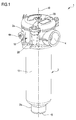
Figure 1 is a perspective view of a filter according to the present invention; -
Figure 2 is a partially exploded perspective view of the filter ofFigure 1 ; -
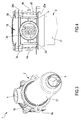
Figure 3 is a bottom perspective view of a filter according to the present invention; -
Figure 4 is a side view of a portion of the filter according to the present invention; -
Figure 5 is a perspective view of a container according to the filter object of the present invention; -
Figure 6 is a perspective view of the filtering cartridge according to the filter object of the present invention; -
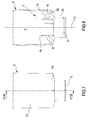
Figure 7 is a front view of a portion of the container; -
Figure 8 is a cross-section view, along the line VII-VII, of the container inFigure 7 ; -
Figure 9 is a detailed view of a portion of the container; -
Figure 10 is a detailed view of a portion of the filtering cartridge; -
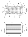
Figure 11 is a front view of a filtering cartridge of the filter object of the present invention; -
Figure 12 is a cross-section view, along the line XII-XII, of the filtering cartridge inFigure 11 ; -
Figure 13 is a detailed view of the filtering cartridge ofFigure 12 ; -
Figure 14 is an exploded view of a portion of the filtering cartridge of the filter object of the present invention; -
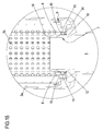
Figure 15 is a detail of a cross-section view of the filter object of the present invention; -
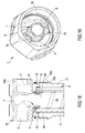
Figure 16 is a perspective view of an embodiment variant of a filter according to the present invention; -
Figure 17 is a cross-section view of the filter inFigure 16 ; -
Figure 18 is a detailed view of the cross-section view inFigure 17 ; -
Figure 19 is a detailed perspective view of a particular of the filter inFigure 16 ; -
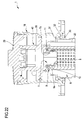
Figure 20 is a perspective view of an embodiment variant of a filter according to the present invention; -
Figure 21 is a cross-section view of the filter inFigure 20 ; -
Figure 22 is a detailed view of the cross-section view inFigure 21 ; -
Figure 23 is a detailed exploded view of the filter inFigure 20 ; -
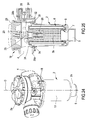
Figure 24 is a perspective view of an embodiment variant of a filter according to the present invention; -
Figure 25 is a cross-section view of the filter inFigure 24 . - A filter for hydraulic fluids for hydraulic circuits has been generally indicated by 1. The
filter 1 can find an advantageous application, generally, in all the hydraulic circuits, inside which it is required to supply a clean oil, in other words devoid of solid, liquid and gas type contaminant substances. For example, thefilter 1, object of the present invention, can be used in industrial plants, construction machines, agricultural machines, hoisting and transporting vehicles. - Particularly, the
filter 1, object of the present invention, can find application in lubrication or filtering systems of the submersible, semi-submersible or pressurized type. - As it is visible in
Figures 1-4 ,16, 20, 24 , for example, thefilter 1 comprises acontainer 2 defining inside at least one housing compartment 3 fluidically communicating with at least oneinlet 4 and at least oneoutlet 5 associated to saidcontainer 2. More particularly, thecontainer 2 exhibits a tubular shape extending between a first andsecond ends container 2 exhibiting, in a non limiting way, a substantially cylindrical shape; however, it is possible to provide acontainer 2 having for example a prismatic shape (this condition is not illustrated). Advantageously, thecontainer 2 has an elongated shape, in other words extending along a prevalent development direction D: thecontainer 2 develops between the first andsecond ends inlet 4 andoutlet 5 of thecontainer 2 can be disposed in proximity with each other (seeFigure 16 , for example) or can be disposed oppositely to each other as illustrated inFigures 1 ,20 and24 for example. - Specifically, in the embodiment in
Figure 16 , theinlet 4 andoutlet 5 are both disposed at thefirst end 2a of thefilter 1. Viceversa, inFigures 1 ,20 and24 , theinlet 4 is disposed at thefirst end 2a while theoutlet 5 is opposite to theinlet 4 and particularly is disposed at thesecond end 2b. In this latter configuration, thefirst end 2a is substantially the top of thefilter 1 on which theinlet 4 is located: moreover, theinlet 4 can be disposed on a lateral wall of the container (facing laterally as illustrated in the attached figures) or can be disposed on the top (this condition is not illustrated in the attached figures). - The attached figures illustrate a preferred but non limiting embodiment of the
filter 1, which exhibits only oneinlet 4 located at thefirst end 2a of thecontainer 2. However, it is possible to provide acontainer 2 exhibiting a plurality of inlets 4 (this condition is not illustrated in the attached figures) or only onemain inlet 4 and one or moreauxiliary inlets 4a (Figures from 1 to 4). Oppositely to the inlet 4 (Figures 1 ,20 and24 ) or at the inlet (Figure 16 ), thecontainer 2 exhibits at least oneoutlet 5 configured for enabling to emit the filtered hydraulic fluid. - As it is visible in
Figure 2 , for example, thecontainer 2 is configured for engaging inside (inside the housing compartment 3) at least onefiltering cartridge 6 configured and positioned for determining the filtering of the hydraulic fluid from theinlet 4; thefiltering cartridge 6 will be better described in the following. - Therefore, for being able to better insert and then engage the
cartridge 6 inside the compartment 3, thecontainer 2 comprises at least onemain body 17 andhead 18 removably engageable with thebody 17. Themain body 17 exhibits a tubular shape and substantially defines the compartment adapted to receive and house thecartridge 6. In the embodiments illustrated in the attached figures, theinlet 4 of thefilter 1 is defined, in a non limiting way, on thehead 18; theoutlet 5 instead can be defined on the main body 17 (seeFigures 1 ,20 and24 for example) or on the same head 18 (seeFigure 16 , for example). Thehead 18 is configured for substantially defining a closure element (lid) of the main body 17 (the attached figures illustrate, in a non limiting way, a configuration of thehead 18 having aninlet 4 and a plurality ofauxiliary inlets 4a - seeFigure 4 , for example). - The possibility of providing two elements removably engageable with each other (the
main body 17 and head 18) enables to insert and then engage thecartridge 6 inside themain body 17 when thehead 18 is separated from this latter; upon engaging thecartridge 6, it is possible to close thecontainer 2 by engaging thehead 18 with thebody 17. - In the embodiments illustrated in
figures 1 ,20 ,24 for example, thehead 18 comprises alower body 28 having a substantially cylindrical tubular shape: thelower body 28 extends between a first andsecond ends Figure 2 , for example). In the arrangements illustrated in the attached Figures, thelower body 28 of thehead 18, carries at the cylindrical lateral wall, a kind of manifold emerging outside the lateral wall of thebody 28 and defining theinlet 4 of the filter configured for enabling to introduce fluids inside this latter. As it is visible, thehead 18 further comprises an upper body orlid 29 tightly engaged with the lower body 28: thelower body 28 is interposed between theupper body 29 of thehead 18 and themain body 17 of thecontainer 2. - More particularly and as it is visible in
Figures 22 and25 for example, thelower body 28 of thehead 18 comprises anabutment portion 30 defined by a circular crown emerging inside thebody 18 itself from the lateral wall; theabutment portion 30 of thehead 18 is configured for abutting against arespective abutment portion 31 of themain body 17 located at a longitudinal end emerging outside the lateral wall of the same. Aseal 32 is interposed between saidabutment portions main body 17 into the head 18 (theabutment portions upper body 29 is engaged with thelower body 28 which is configured for axially constraining thehead 18 andmain body 17. - Advantageously, the
filter 1 further comprises at least one thrusting element 23 - for example a spring - engaged inside the compartment 3 and configured for contacting, on one side, thehead 18 of thecontainer 2 and, on the other side, thefiltering cartridge 6. Particularly, the pushingelement 23 is interposed between theupper body 29 of thehead 18 and thefiltering cartridge 6. The thrustingelement 23 is configured for exerting, during the closed condition of thecontainer 2, a force acting on thecartridge 6 for maintaining this latter stably engaged inside themain body 17. The thrustingelement 23 can advantageously comprise a spring adapted to work, under compression, between thehead 18 andcartridge 6. Advantageously, thehead 18 andcartridge 6 comprise respective centeringportions 24 adapted to grip the spring and guide it during the closing step of thecontainer 2 and during the thrusting step. - In the just described embodiment of the head (engagement between the head and main body by the
abutment portions 30 and 31), theupper body 29 can reversibly engage thebody 28 to the head by means of screws (seeFigure 2 , for example) or theupper body 29 can be screwed on thebody 28 of the head (seeFigures 22 and25 for example). - In a further embodiment illustrated in Figures from 16 to 19, the
lower body 28 comprises, at thefirst end 28a, a threadedportion 33, particularly an inner thread of thehead 18, configured for cooperating with the threadedportions 33a, particularly an outer thread, of themain body 17 of the container 2: the threads ensure the reversible engagement between themain body 17 andhead 18 for consequently blocking thecartridge 6 as it will be better described in the following. - More particularly, it is possible to observe that the
container 2 further comprises at least oneengagement portion 7 projecting inside the housing compartment 3, particularly along a prevalent development direction parallelly to the prevalent development direction of the main body 17: theengagement portion 7 is configured for engagingly receiving thefiltering cartridge 6. - In the embodiment illustrated in Figures from 1 to 15 and 25, the
engagement portion 7 of thecontainer 2 is located at thesecond end 2b of thecontainer 2 and particularly at the outlet 5: under such arrangement, theengagement portion 7 exhibits an open passage which directly fluidically communicates with theoutlet 5. Advantageously, theengagement portion 7 is stably supported, particularly is formed in one piece (in a single body) with themain body 17. - In a further embodiment variant, the
engagement portion 7 of thecontainer 2 is defined at thefirst end 2a and particularly at theinlet 4 of the container 2 (see -
Figures 18 and22 ). More particularly, in this last described configuration, theengagement portion 7 is defined on thehead 18 of thecontainer 2 and emerges for approaching themain body 7. In this last described configuration, theengagement portion 7 can exhibit a through opening fluidically directly communicating with the outlet or can define a blind body devoid of apertures as for example illustrated inFigure 19 . - The
engagement portion 7 of thecontainer 2 defines at least onecollar 7a having an outer lateral coupling surface 8 (seeFigures 8 ,15 ,18 ,22 and25 , for example). Thecollar 7a extends also along the prevalent development direction D of the container 2: theouter coupling surface 8 is, for at least one segment of the development of the same, substantially parallel to the direction D. - Particularly, the
collar 7a extends from a base orbottom portion 34 of thecontainer 2 towards the filteringcartridge 6 to a free edge 16 (seeFigure 9 , for example). De facto, thecollar 7a exhibits an extension, defined by the minimum distance, measured between thebase portion 34 to thefree edge 16, equal to or greater than 5 mm, particularly comprised between 5 and 100 mm, still more particularly between 7 and 25 mm, optionally about 12 mm. Theouter coupling surface 18 defines at least partially saidcollar 7a and exhibits an extension equal to or greater than 5 mm, particularly comprised between 5 and 100 mm, still more particularly between 7 and 25 mm, optionally about 12 mm. - As it is visible in
Figure 9 , theouter coupling surface 8 of thecollar 7a exhibits, along a section normal to the prevalent development direction of thecollar 7a itself, a polygonal type shape. More specifically, theouter coupling surface 8 exhibits a cross-section defining a closed outline having a simple polygonal shape, and particularly a regular shape. In a preferred but non limiting embodiment of the invention, thecoupling surface 8 exhibits, along a section normal to the prevalent development direction of thecollar 7a itself, a hexagonal shape. The cross-section extends along a plane transversal, particularly normal, to the extension direction of theouter surface 8 itself, optionally normal to the prevalent development direction D of thecontainer 2. Advantageously, thecollar 7a of theengagement portion 7 comprises a projection configured for receiving anengagement portion 9 of thefiltering cartridge 6 as it will be better described in the following. - In the embodiments of the
filter 1 outlined inFigures 2 ,17 and25 for example, thecontainer 2 comprises only oneengagement portion 7. In such configuration and as it will be better described in the following, thefiltering cartridge 6 is engaged between theportions 7 of thecontainer 2 and the thrusting element 23 (seeFigure 25 for example). Alternatively, as illustrated inFigure 17 , in the presence of thesingle engagement portion 7, thecartridge 6 can be engaged between theengagement portion 7 and the bottom of themain body 17 of thecontainer 2. - However, in a further embodiment variant, the
container 2 can comprise a further engagement portion 35 (Figure 21 ) projecting inside the housing compartment 3 oppositely theengagement portion 7 and which is configured for engagingly receiving thefiltering cartridge 6. - The
further engagement portion 35 of thecontainer 2 is located at thesecond end 2b of thecontainer 2 and particularly at the outlet 5: in such configuration, thefurther engagement portion 35 exhibits an open passage directly fluidically communicating with theoutlet 5. - The
further engagement portion 35 of thecontainer 2 defines also acollar 35a having an outer coupling lateral surface 36 (seeFigure 21 , for example). Thecollar 35a extends also along the prevalent development direction D of the container 2: theouter coupling surface 36 is, for at least a segment of the development thereof, substantially parallel to the direction D and particularly parallel to theouter coupling surface 8 of theengagement portion 7. Particularly, thecollar 35a extends from a base orbottom portion 37 of thecontainer 2 towards the filteringcartridge 6 to a free edge 38 (seeFigure 21 , for example). - De facto, the
collar 35a exhibits an extension defined by the minimum distance measured between thebase portion 37 to thefree edge 38, equal to or greater than 5 mm, particularly comprised between 5 and 100 mm, still more particularly between 7 and 25 mm, optionally about 12 mm. Theouter coupling surface 36 defines at least part of saidcollar 35a and exhibits an extension equal to or greater than 5 mm, particularly comprised between 5 and 100, still more particularly between 7 and 25 mm, optionally about 12 mm. - The
outer coupling surface 36 of thecollar 35a can provide, according to a section normal to the prevalent development direction of the collar itself, a shape having at least two symmetry axes. Particularly, theouter coupling surface 36 can exhibit a polygonal shape (for example a hexagonal one substantially identical in shape and/or size to the shape of the engagement portion 7), a cylindrical or elliptical shape. - As for the
engagement portion 7, also thecollar 35a can comprise a projection configured for receiving outside an engagement portion of thefiltering cartridge 6 as it will be better described in the following. In such configuration, thefiltering cartridge 6 is engaged between theengagement portion 7 and thefurther engagement portion 35. - From the point of view of the materials, the
container 2 can be made at least partially of a plastic or metal material; for example, at least of a material selected in the group comprising: aluminum, nylon, steel, cast iron. For example, themain body 17 andhead 18 can be made of the same material or of distinct materials, for example of aluminum, nylon, steel, cast iron. In a preferred but non limiting embodiment of the invention, themain body 17 of thecontainer 2 is made at least partially of nylon, while thehead 18 is made at least partially of aluminum; such selection can be advantageous for defining semi-submersible filters, in which the submerged part, represented by themain body 17, is made of a plastic material (for example nylon) resistant to corrosion, while the head 18 (element which is not submerged) represents the part destined to fix the filter 1 (for example for fixing it to a circuit or reservoir) and is therefore advantageously made of a material adapted to provide good structural characteristics, for example, of aluminum. Obviously, it is not excluded the possibility of making, for some applications, for example for submerged filters or pressurized filters, amain body 17 and the associatedhead 18 completely of a structural material, for example of aluminum, or completely of a corrosion-resistant material, for example of plastic. - As hereinbefore briefly discussed, the
filter 1 further comprises at least onefiltering cartridge 6 representing the element configured for performing the filtering operation and therefore for enabling a selective passage of the hydraulic fluid. Thecartridge 6 is engageable inside thecontainer 2 and partitions the housing compartment 3 into afirst chamber 3a fluidically communicating with theinlet 4, and asecond chamber 3b fluidically communicating with theoutlet 5. More particularly, thefirst chamber 3a directly fluidically communicates with theinlet 4 and is configured for receiving, at the inlet, the fluid to be treated; thesecond chamber 3b directly fluidically communicates with theoutlet 5 and is configured for receiving the treated fluid. Thecartridge 6 is configured and positioned for determining the filtering of the hydraulic fluid from theinlet 4 which flows from the first to thesecond chambers cartridge 6 is configured for being inserted inside themain body 17 and engaging theengagement portion 7 of thecontainer 2. In the configuration illustrated inFigure 25 for example, thefiltering cartridge 6 is stably engageable between theengagement portion 7 of thecontainer 2 and the thrustingelement 23 which partially acts on thecartridge 6 and partially on thehead 18. In the configuration of thecontainer 2 supporting theportions filtering cartridge 6 is engaged between thecollars engagement portions - Moreover, the
head 18 can further comprise an intermediate body 40 (seeFigure 23 ) configured for being engaged inside thelower body 28. In an assembled condition of thehead 18, theintermediate body 40 is closed at the top by the upper body 29 (seeFigure 22 ). Theintermediate body 40 comprises a disk-shapedportion 41 from which emerges a top portion provided with one ormore apertures 42 for discharging the fluid from theintermediate body 40. Preferably but in a non limiting way, theintermediate body 40 supports theengagement portion 7. Theengagement portion 7 develops oppositely to the top portion. - The
intermediate body 40 is configured for defining, in cooperation with thehead 18, a first compartment fluidically communicating with theinlet 4 and a second compartment fluidically communicating with theoutlet 5. In the operative conditions of thefilter 1, the fluid enters from theinlet 4, flows into the first compartment defined between theintermediate body 40 andlower body 28, then flows into thefirst chamber 3a by flowing down thecontainer 2, crosses the filtering cartridge 6 (therefore is filtered) and flows up inside thesecond chamber 3b. By flowing up inside thecontainer 2, the filtered fluid is conveyed inside theengagement portion 7 and therefore inside theintermediate body 40. The fluid exits therefore from theintermediate body 40 through theapertures 42, through the second compartment between theintermediate body 40 andlower body 28 and exits the filter from theoutlet 5. - Advantageously, the
filtering cartridge 6 exhibits, in a non limiting way, a shape substantially countershaped to thecontainer 2; the attached figures schematically show acartridge 6 having a substantially cylindrical shape and at least partially countershaped to themain body 17. More particularly, thecartridge 6 comprises at least one tubular supportingelement 19 extending between a first andsecond ends element 19 advantageously exhibits a hollow cylindrical shape extending along a prevalent development direction; during the engagement condition between thecartridge 6 andcontainer 2, this latter extends along respective prevalent development directions parallel to each other, optionally along parallel and coincident directions. Moreover, thecartridge 6 comprises at least onefiltering membrane 20 configured for enabling a fluid to selectively pass through the membrane itself; themembrane 20 is adapted to laterally cover the supportingelement 19. Themembrane 20 covers the holes of the supportingelement 19 and controls the selective passage of the working fluid so that said holes are only crossed by a filtered (purified) fluid. Themembrane 20 is engaged around the supportingelement 19 in order to define at least one pleated layer. Themembrane 20 can comprise only one layer or can comprise a plurality of layers overlappingly wrapped on each other for increasing the filtering capacity of thecartridge 6. - As it is visible in
Figures 6 ,12 ,17 ,21 and25 for example, thecartridge 6 further comprises at least one first and onesecond blocking elements second ends elements cartridge 6. Thefirst blocking element 21 substantially comprises a lid adapted to stably engage the supportingelement 19 at thefirst end 19a and to temporarily block the membrane 20: the membrane is fixed, for example by gluing, to thefirst blocking element 21 which in turn is stably constrained to theelement 19. - In a first embodiment of the
cartridge 6 illustrated inFigures 6 ,12 ,17 and25 for example, thefirst blocking element 21 substantially comprises a plug which can exhibit at least one centeringportion 24 emerging oppositely to theelement 22 and which is configured for engaging the thrusting element 23 (Figure 5 ). - Advantageously, the
first blocking element 21 further comprises at least one throughopening 25 fluidically communicating with an inner volume of the supportingelement 19 and in correspondence of which abypass valve 26 can be positioned. Thebypass valve 26 is configured for being placed, under a normally closed condition, in which prevents the fluid communication between the inlet 4 (between thefirst chamber 3a) and the inner volume of the supporting element 19 (second chamber 3b): under such condition, the fluid entering thefilter 1 is "constrained" to flow through themembrane 20. Further, thebypass valve 26 is configured for being placed in a passage condition wherein it enables the fluid to flow between the inlet 4 (between thefirst chamber 3a) and the inner volume of the supporting element 19 (second chamber 3b). Switching from the normally closed condition to the passage condition is automatically managed by thevalve 26 as the pressure of the hydraulic fluid inside thefirst chamber 3a increases: indeed, above a determined pressure threshold, the bypass valve opens for enabling the fluid to flow (vent) through the opening 25: an overlapping condition could verify in case the filtering capacity of themembrane 20 is compromised. Thebypass valve 26 is, in a non limiting way, positioned inside the supportingelement 19 and can comprise a check valve adapted to only enable a fluid passage entering the supportingelement 19. - Still considering this latter embodiment of the
cartridge 6, oppositely to thefirst blocking element 21, thecartridge 6 comprises thesecond blocking element 22 also adapted to substantially define a lid stably engaged to the supportingelement 19 at thesecond end 19b and configured at least for blocking the membrane 20: therefore themembrane 20 is fixed at the ends, for example by gluing, to the first andsecond blocking elements element 19. However, in such configuration, thesecond blocking element 22, unlike thefirst blocking element 21, comprises a through opening always directly fluidically communicating with thefirst chamber 3a of the compartment 3 and therefore with the inner volume of the supportingelement 19. Thesecond blocking element 22, besides defining the lower fixing element of themembrane 20, is configured for defining the engagement element of thecartridge 6 to the container 2 (seeFigures 6 ,12 and25 , for example). De facto, thesecond blocking element 22 comprises arespective engagement portion 9 defining arespective collar 9a extending along a prevalent development direction which, in an engagement condition between thecontainer 2 andcartridge 6, is parallel to the prevalent development direction D of thecontainer 2. Particularly, the directions are parallel and coincident to each other (the prevalent development direction is the same). More particularly, the prevalent development direction of theengagement portion 9a of thefiltering cartridge 6 extends along a prevalent development direction which, under an engagement condition between thecontainer 2 andcartridge 6, is parallel to the prevalent development direction of theouter coupling surface 8 of thecontainer 2. - As it is visible in the attached figures, the
collar 9a of theengagement portion 9 of thecartridge 6 comprises an innerlateral coupling surface 10 configured for engaging outside theouter coupling surface 8 of thecontainer 2; more particularly, theinner coupling surface 10 of theengagement portion 9 of thecartridge 6 is countershaped to theouter coupling surface 8 of thecontainer 2, particularly exhibiting a cross-section having a polygonal shape. More specifically, theinner coupling surface 10 of thefiltering cartridge 6 can exhibit, along a section transversal to the prevalent development direction of thecollar 9a, a simple polygonal section, particularly a regular polygonal one. In a preferred but non limiting embodiment of the invention, theinner coupling surface 10 exhibits a hexagonal shape. - De facto, also the
inner coupling surface 10 of thecollar 9a extends along a respective prevalent development direction which, at least during the engagement condition between thecollars outer coupling surface 8, optionally parallel to the prevalent development direction D of thecontainer 2. Still more particularly, theinner coupling surface 10 of thefiltering cartridge 6 is countershaped to theouter coupling surface 8 of thecontainer 2. As for the previous surfaces, the cross-section is the one along a plane transversal, particularly normal, to the extension direction of theinner coupling surface 10 itself and therefore transversal, optionally normal, to the prevalent development direction D of thecontainer 2. - It is evident that the polygonal configuration, particularly the hexagonal one, of the coupling surfaces 8, 10 respectively of the
container 2 andcartridge 6, prevents these latter from reciprocally rotate around an axis parallel to the extension direction of said surfaces. With reference to possible axial movements, these are prevented due to the presence of the thrustingelement 23 or a further engagement portion 35 (the embodiment ofFigures 2 and25 ) which exerts a force adapted to hold theengagement portions cartridge 6 is prevented from sliding inside themain body 17 of thecontainer 2 at least in the presence of thehead 18. - Advantageously but in non a limiting way, the
collar 9a of thefiltering cartridge 6 comprises a projection emerging from thesecond blocking portion 22 configured for receiving inside thecollar 7a of thecontainer 2. As it is visible for example inFigures 10 ,12 and13 , the projection defined by thecollar 9a is laterally delimited by an outer lateral surface and an inner lateral surface: thecoupling surface 10 of thefiltering cartridge 6 is defined by at least part of the inner lateral surface of thecollar 9a of saidfiltering cartridge 6. De facto, the projection of thecollar 9a extends along a direction parallel to the extension direction of thecollar 7a and consequently parallel to the prevalent development direction D of thecontainer 2. Advantageously, thecollar 9a develops from a root of thesecond blocking element 22 to a free edge. - Preferably but in a non limiting way, the
collar 9a comprises a first andsecond bodies coupling surface 10 and at least one groove configured for housing aseal 11, as it will be better described in the following. Particularly, the first andsecond bodies inner coupling surface 10 of theengagement portion 9 of thefiltering cartridge 6 itself. Thefirst body 13 comprises a through opening defining, on the first body itself, part of theinner coupling surface 10 of thefiltering cartridge 6. In turn, thesecond body 14 comprises a respective opening defining, on the second body itself, part of theinner coupling surface 10 of the filtering cartridge. The first andsecond bodies filtering cartridge 6 for defining thecoupling surface 10 of thecollar 9a of thefiltering cartridge 6 itself. Preferably, at least one between the first andsecond bodies collar 9a of thefiltering cartridge 6 comprises a groove configured for defining, under the reciprocal coupling condition of the first andsecond bodies perimetral cavity 12 of thecollar 9a of thefiltering cartridge 6 itself. - In a further configuration of the
filtering cartridge 6 illustrated inFigure 2 for example, also thefirst blocking element 21 comprises anengagement portion 39 substantially similar to theengagement portion 9 of the cartridge itself. De facto, theengagement portion 39 of the first blocking element can be identical to theopposite engagement portion 9; unlike theengagement portion 9, theportion 39 of thefirst blocking element 21 can exhibit an inner coupling surface having a circular shape. - The
engagement portion 39 of thefirst blocking element 21 is configured for engaging thefurther engagement portion 35 of thecontainer 2. Specifically, theouter coupling surface 36 of thefurther engagement portion 35 is configured for engaging the inner coupling surface of theengagement portion 39 of the first blocking element 21: theportion 39 is outwardly constrained to theouter coupling surface 36 of theengagement portion 35 of the container. De facto, under the configuration illustrated inFigure 21 , the filter comprises twoengagement portions engagement portions filtering cartridge 6. - In a preferred but non limiting embodiment of the invention, also the
engagement portion 39 defined on the first blocking element exhibits a structure identical to the one of theengagement portion 7 wherein the same is defined by the first and second bodies (elements 13 and 14) constrained to each other, particularly in a reversible way, for defining saidcoupling surface 36. - As it is visible in
Figures 10 ,12 ,13 and17 for example, thefilter 1 further comprises at least oneseal 11 interposed between theengagement portions container 2 and the filtering cartridge 6: theseal 11 forms a closed perimetral element, interposed between the coupling surfaces 8 and 10, configured for defining the fluid tightness between thefiltering cartridge 6 andcontainer 2. The attached figures illustrate a non limiting configuration of thefilter 1, exhibiting only oneseal 11; however, it is possible to provide afilter 11 having two or more seals 11. - Advantageously, the
seal 11 is stably supported by thecollar 3a of thefiltering cartridge 6, particularly is supported by the inner lateral surface of thecollar 9a (theseal 11 is interposed between the coupling surfaces 8, 10). De facto, the inner lateral surface of thecollar 9a of thefiltering cartridge 6 exhibits a perimetral cavity 12 (Figure 13 ) extending all around saidcollar 9a for defining a closed outline having a substantially "C" shape having the concavity facing thecoupling surface 10 itself; theseal 11 is stably engaged at least partially inside saidperimetral cavity 12 and partially emerges for contacting theouter coupling surface 8 of thecontainer 2. As it is visible in the attached figures, theseal 11 comprises a body having a shape as the coupling surfaces 8, 10, particularly a polygonal one, specifically countershaped to theinner coupling surface 10 of thecollar 9a. Instead, with reference to the cross-section of the seal, this is defined by a circular or elliptical shape. - From the point of view of the materials, the
cartridge 6 is also made of metal or plastic material. However, preferentially thecartridge 6 is substantially completely made of plastic material, particularly of nylon, except for themembrane 20. De facto, almost all the components of thecartridge 6 are adapted to contact the working fluid; therefore, it is advantageous that the material of which thecartridge 6 is made, can resist to the chemical attacks of the fluid. Advantageously, the supportingelement 19 is made of a plastic and/or metal materials; specifically, the supportingelement 19 can be made of at least one of the following materials: nylon, aluminum, steel, cast iron. The supportingelement 19 of plastic material is obtainable for example by extrusion or moulding while the supportingelement 19 of metal material is obtainable, for example, by calendering and welding. The blockingelements second element 22, is made of plastic material, for example of nylon. Viceversa, thebypass valve 26 could be made at least partially of a plastic and/or metal materials. With reference to the material of theseal 11, this latter is at least made partially, particularly completely, of a plastic material and is obtained by moulding; optionally theseal 11 is made of an elastomeric material, for example at least partially of nylon. anyway, the preferred but non limiting configuration of thecartridge 6 is the one which provides blockingelements - Moreover, the invention refers to a process for making the above described
filter 1 for hydraulic fluids for hydraulic circuits. Firstly, the process comprises providing thecontainer 2 which can be made by moulding or extruding a metal or plastic material. During the step of providing thecontainer 2, it is formed theengagement portion 7 exhibiting anouter coupling surface 8 having a polygonal cross-section, particularly a simple polygonal one, still more particularly a regular polygonal one, optionally a hexagonal shape. In the preferred but non limiting embodiment of the invention, themain body 17 is made of plastic material and obtained by moulding: during such step, it is obtained theengagement portion 7 as hereinbefore described. Also thehead 18 of thecontainer 2 can be made of plastic of metal material therefore, and is obtainable by moulding or melting respectively. Themain body 17 andbody 18 are anyway separately made and engaged afterwards for enabling to insert thecartridge 6. - Moreover, the process provides making the
cartridge 6 which comprises the step of making the supportingelement 19 which, as hereinbefore described, can be made of plastic or metal material and is obtained by moulding or extrusion. Providing thecartridge 6 comprises forming theengagement portion 9 exhibiting aninner coupling surface 10 at least partially countershaped to thecoupling surface 8 of thecontainer 2. As previously discussed, theinner coupling surface 10 can have a cross-section having a simple polygonal shape, particularly a regular polygonal shape, still more particularly a hexagonal one. Providing thecartridge 6 further comprises providing a first andsecond bodies collar 9a of the engagement portion 9 (seeFigure 14 ) as hereinbefore described. The first andsecond bodies seal 11 is defined on one of the twobodies - Providing the
cartridge 6 further comprises forming the blockingelement elements opening 25 and the centeringportion 24 for thesecond element 21 and theengagement portion 9 for thesecond blocking element 22 are formed. Moreover, the process provides a step of forming theseal 11 of the above described type; particularly, theseal 11 has a polygonal type closed outline and is countershaped to theinner coupling surface 10 of the filtering cartridge. Preferably, theseal 11 exhibits a circular cross-section. - Moreover, providing the
cartridge 6 comprises engaging themembrane 20 around the supportingelement 19; such step consists of positioning themembrane 20 around the lateral wall of theelement 19 so that this latter is pleated around this latter. Then, theelements element 19 and themembrane 20 is glued to saidelements - The process then provides the step of assembling the
filter 1, which provides to insert the cartridge inside themain body 17, thesecond blocking element 22 facing theoutlet 5. Upon centering thecartridge 6, this latter is further thrusted inside thebody 17 in order to define the engagement between theportions container 2 and cartridge 6: the step of coupling thesurfaces seal 11 between theengagement portions seal 11 is engaged inside the groove of the first and/orsecond bodies second bodies inner coupling surface 10 of thecollar 9a of thefiltering cartridge 6. The step of centering the cartridge enables to orient thecollar 9a so that, for engaging theportions cartridge 6, the process provides to position the thrustingelement 23 between thecartridge 6 andhead 18 and then to fix this latter to themain body 17. The step of fixing thehead 18 thrusts theelement 23 against the cartridge which is therefore axially blocked against theengagement portion 7 of thecontainer 2; then, therefore fixing thehead 18 to thebody 17 prevents any relative (both axial and rotative) movement of thecontainer 2 andcartridge 6. - The present invention brings relevant advantages with respect to the filters belonging to the state of the art. The
filter 1 exhibits the coupling surfaces 8, 10 having a polygonal shape, which prevent the relative rotation between the container and cartridge. Moreover, the presence of the coupling surfaces 8, 10 having respective polygonal cross-sections and particularly a hexagonal one, enables to define a highly stable coupling between thecontainer 2 andcartridge 6, by advantageously evenly distributing the stresses. Moreover, providing the coupling surfaces 8, 10 having respective polygonal cross-sections enables to define different engagement positions (operative positions) of the cartridge to the container, in order to enable a fast and simplified assembly of thefilter 1. A further advantage is defined by the simple manufacture of thefilter 1 which therefore is readily assemblable; the structure of all the components ensures to correctly position theseal 11 between the coupling surfaces 8 and 10 so that a correct tightness and consequently an efficient filtering are ensured. Simplifying the assembly step makes particularly easy the step of making the same and possibly to disassemble it, which in turn reduces at the minimum the cost for manufacturing thefilter 1.
the filtering cartridge (6) exhibiting a respective engagement portion (9) defining a respective collar (9a) exhibiting an inner coupling lateral surface (10) configured for tightly engaging outside the outer coupling surface (8) of the container (2),
the outer coupling surface (8) of the engagement portion (7) of the container (2) exhibiting, along a cross-section, a polygonal shape, the inner coupling surface (10) of the engagement portion (9) of the cartridge (6) being at least partially countershaped to the outer coupling surface (8) of the container (2), said outer and inner coupling surfaces (8, 10) being configured for cooperating with each other to define a removable engagement between the filtering cartridge (6) and container (2).
and wherein the step of providing the filtering cartridge (6) provides forming a respective engagement portion (9) exhibiting an inner coupling surface (10) at least partially countershaped to the outer coupling surface (8) of the container (2).
Claims (14)
- Filter (1) for hydraulic fluids for hydraulic circuits, comprising:- a container (2) exhibiting inside at least one housing compartment fluidically communicating with at least one inlet (4) and at least one outlet (5) associated to said container (2),- at least one filtering cartridge (6) engageable with the container (2) inside the housing compartment (3), the filtering cartridge (6) partitioning the housing compartment (3) in a first chamber (3a) fluidically communicating with the inlet (4) and a second chamber (3b) fluidically communicating with the outlet (5), the filtering cartridge (6) being configured and positioned for determining the filtering of the hydraulic fluid from the inlet (4) and passing from the first to the second chambers (3a, 3b),the container (2) exhibiting at least one engagement portion (7) projecting inside the housing compartment and defining at least one collar (7a) having an outer coupling lateral surface (8),
the filtering cartridge (6) exhibiting a respective engagement portion (9) defining a respective collar (9a) exhibiting an inner coupling lateral surface (10) configured for tightly engaging outside the outer coupling surface (8) of the container (2);
the outer coupling surface (8) of the engagement portion (7) of the container (2) exhibiting, along a cross-section, a polygonal shape, the inner coupling surface (10) of the engagement portion (9) of the cartridge (6) being at least partially countershaped to the outer coupling surface (8) of the container (2), said outer and inner coupling surfaces (8, 10) being configured for cooperating with each other to define a removable engagement between the filtering cartridge (6) and container (2). - Filter according to the preceding claim, wherein the inner coupling surface (10) of the filtering cartridge (6) is totally countershaped to the outer coupling surface (8) of the container (2), particularly the inner coupling surface (10) of the engagement portion (9) of the filtering cartridge (6) exhibits, along a cross-section, a polygonal shape.
- Filter according to anyone of the preceding claims, wherein the outer coupling surface (8) of the engagement portion (7) of the container (2) exhibits, along a cross-section, a simple polygonal shape, particularly a polygonal shape exhibiting a number of sides equal to or greater than 4, still more particularly comprised between 4 and 8,
and wherein the inner coupling surface (10) of the coupling portion (9) of the filtering cartridge (6) exhibits, according to a cross-section, a simple polygonal shape particularly a polygonal shape exhibiting a number of sides equal to or greater than 4, still more particularly comprised between 4 and 8. - Filter according to anyone of the preceding claims, wherein the outer coupling surface (8) of the engagement portion (7) of the container (2) exhibits, along a cross-section, a regular polygonal shape, particularly a hexagonal shape,
and wherein the inner coupling surface (10) of the engagement portion (9) of the filtering cartridge (6) exhibits, along a cross-section, a regular polygonal shape, particularly a hexagonal shape. - Filter according to anyone of the preceding claims, comprising at least one seal (11) interposed between the engagement portions (7, 9) of the container (2) and filtering cartridge (6), respectively, the seal (11) comprising a closed perimetral element configured for defining the fluid tightness between the filtering cartridge (6) and the container (2), particularly between the engagement portions (7, 9) of the container (2) and filtering cartridge (6), respectively, optionally wherein the seal (11) is stably supported by the collar (9a) of the filtering cartridge (6) and is interposed between the outer and inner coupling surfaces (8, 10) of the container (2) and the filtering cartridge (6), respectively.
- Filter according to the preceding claim, wherein the collar (9a) of the cartridge (6) comprises an inner lateral wall delimiting inside said collar (9a), at least part of the inner lateral wall of the collar (9a) of the cartridge (6) defining the inner coupling surface (10) of the collar (9a) of the cartridge (6), the inner lateral wall of the collar (9a) of the filtering cartridge (6) comprising a perimetral cavity (12) extending all around said collar (9a) to define a closed outline, the seal (11) being stably engaged at least partially inside said perimetral cavity (12), the seal (11) being configured for contacting the outer coupling surface (8) of the container (2) engagement portion (7).
- Filter according to anyone of the preceding claims, wherein the filtering cartridge (6) comprises:- at least one tubular supporting element (19) extending between a first and second ends (19a, 19b) and exhibiting a lateral wall exhibiting a plurality of through holes,- at least one filtering membrane (20) engaged around the lateral wall of the supporting element (19) and configured for enabling the selective passage of a fluid through the membrane itself,- at least one first and one second blocking elements (21, 22) respectively engaged at the first and second ends (19a, 19b) of the supporting element (19), and wherein at least one of the first and second blocking elements (21, 22) of the filtering cartridge (6) comprises the respective engagement portion (9) supporting the respective collar (9a).
- Filter according to anyone of the preceding claims, wherein the collar (9a) of the engagement portion (9) of the cartridge (6) comprises at least one first and one second bodies (13, 14) engageable with each other, particularly reversibly, along an axial direction parallel to an extension direction of the inner coupling surface (10) of the engagement portion (9) of the filtering cartridge (6) itself,
the first body (13) comprising a through opening defining, on the first body itself, part of the inner coupling surface (10) of the filtering cartridge (6),
the second body (14) comprising a respective opening defining on the second body itself, part of the inner coupling surface (10) of the filtering cartridge (6), the first and second bodies being configured for engaging, particularly reversibly, with each other along an axial direction parallel to a prevalent development direction of the filtering cartridge (6) for defining the coupling surface (10) of the collar (9a) of the filtering cartridge (6) itself. - Filter according to the preceding claim, wherein at least the first and/or second bodies (13, 14) of the collar (9a) of the filtering cartridge (6) comprise a groove configured for defining, under the reciprocal coupling of the first and second bodies (13, 14), the perimetral cavity (12) of the collar (9a) of the filtering cartridge (6) itself.
- Filter according to anyone of the preceding claims, wherein the container (2) exhibits a substantially elongated shape, particularly a cylindrical one, extending along a prevalent development direction (D) between a first and second ends (2a, 2b), the engagement portion (7) of the container (2) extends, from a base, parallelly to the prevalent development direction (D) of the container (2) itself, inwardly the filtering cartridge (6), the outer coupling surface (8) of the collar (7a) of the container (2) exhibiting a first section extending inside the cartridge (6) parallelly to the prevalent development direction (D) of the container (2), the outer coupling surface (8) of the container (2) exhibiting a second section extending inside the cartridge, without interruption, with respect to the first section,
the outer coupling surface (8) of the second section being sloped with respect to the prevalent development direction (D) of the container (2) and converging according to a direction entering the filtering cartridge (6), optionally the outer coupling surface (8) of the collar (7a) of the container (2) being sloped with respect to the prevalent development direction (D) of the container (2) with an angle comprised between 1° and 5°, particularly comprised between 1° and 3°. - Process of making a filter (1) for hydraulic fluids for hydraulic circuits according to anyone of the preceding claims, said process comprising at least the following steps:- providing the container (2) exhibiting at least one engagement portion (7) projecting inside the housing compartment and defining at least one collar (7a) having an outer coupling lateral surface (8),- providing the filtering cartridge (6) exhibiting a respective engagement portion (9) defining a respective collar (9a) exhibiting an inner coupling lateral surface (10) configured for tightly engaging outside the outer coupling surface (8) of the container (2),and wherein the step of providing the container (2) provides to form an engagement portion (7) exhibiting an outer coupling surface (8) having a polygonal cross-section,
and wherein the step of providing the filtering cartridge (6) provides to form a respective engagement portion (9) exhibiting an inner coupling surface (10) at least partially countershaped to the container (2) coupling surface (8). - Process according to the preceding claim, wherein the step of forming the engagement portion of the filtering cartridge (6) provides to form an inner coupling surface (10) having a simple polygonal shape cross-section, particularly a regular polygonal shape, still more particularly a hexagonal shape,
the process comprises at least one step of engaging the container (2) and filtering cartridge (6) adapted to engage the outer and inner coupling portions (8, 10) respectively of the container (2) and filtering cartridge (6). - Process according to claim 11 or 12 comprising at least the following steps:- forming at least one closed outline seal (11) of the polygonal type countershaped to the inner coupling surface (10) of the filtering cartridge and having a circular cross-section,- engaging said seal (11) between the engagement portions (7, 9) of the container (2) and cartridge (6), respectively,the seal (11) comprising a closed perimetral element configured for defining the fluid tightness between the filtering cartridge (6) and container (2), particularly, the seal (11) is stably supported by the collar (9a) of the filtering cartridge (6) and is interposed between the coupling surfaces (8, 10) of the container (2) and filtering cartridge (6), respectively.
- Process according to anyone of claims from 11 to 13, wherein the step of providing the filtering cartridge (6) comprises at least the following steps:- forming the first body (13) of the collar (9a) of the engagement portion (9) exhibiting a through opening,- forming the second body (14) of the collar (9a) of the engagement portion (9) exhibiting a respective through opening,- defining on the first and/or second bodies a perimetral groove configured for receiving at least part of the seal (11),- providing the seal (11) inside the groove of the first and/or second bodies (13,14),- engaging the first and second bodies (13, 14) so that the respective openings are aligned to define the inner coupling surface (10) of the collar (9a) of the filtering cartridge (6), following the engagement between the first and second bodies, the seal (11) being interposed between these latter.
Priority Applications (1)
| Application Number | Priority Date | Filing Date | Title |
|---|---|---|---|
| PL16181725T PL3124092T3 (en) | 2015-07-30 | 2016-07-28 | Filter for hydraulic fluids for hydraulic circuits and process of making the same |
Applications Claiming Priority (1)
| Application Number | Priority Date | Filing Date | Title |
|---|---|---|---|
| ITUB2015A002615A ITUB20152615A1 (en) | 2015-07-30 | 2015-07-30 | HYDRAULIC FLUID FILTER FOR HYDRAULIC CIRCUITS AND PROCEDURE FOR THE REALIZATION OF THE SAME |
Publications (2)
| Publication Number | Publication Date |
|---|---|
| EP3124092A1 true EP3124092A1 (en) | 2017-02-01 |
| EP3124092B1 EP3124092B1 (en) | 2021-05-12 |
Family
ID=54329968
Family Applications (1)
| Application Number | Title | Priority Date | Filing Date |
|---|---|---|---|
| EP16181725.9A Active EP3124092B1 (en) | 2015-07-30 | 2016-07-28 | Filter for hydraulic fluids for hydraulic circuits and process of making the same |
Country Status (10)
| Country | Link |
|---|---|
| US (1) | US11215205B2 (en) |
| EP (1) | EP3124092B1 (en) |
| CA (1) | CA2937258C (en) |
| DK (1) | DK3124092T3 (en) |
| ES (1) | ES2879992T3 (en) |
| HU (1) | HUE055513T2 (en) |
| IT (1) | ITUB20152615A1 (en) |
| LT (1) | LT3124092T (en) |
| MA (1) | MA41589B1 (en) |
| PL (1) | PL3124092T3 (en) |
Cited By (2)
| Publication number | Priority date | Publication date | Assignee | Title |
|---|---|---|---|---|
| WO2018197149A1 (en) * | 2017-04-27 | 2018-11-01 | Rt-Filtertechnik Gmbh | Filter device |
| US10589203B1 (en) | 2018-11-07 | 2020-03-17 | Hydac Technology Corporation | Filter device |
Families Citing this family (7)
| Publication number | Priority date | Publication date | Assignee | Title |
|---|---|---|---|---|
| DE202017102087U1 (en) * | 2017-04-07 | 2018-07-11 | Boll & Kirch Filterbau Gmbh | Filter element and filter assembly with fluid filter and filter element |
| WO2018237252A1 (en) * | 2017-06-23 | 2018-12-27 | Sogefi Air & Cooling Usa, Inc. | Serviceable oil filter assembly |
| USD954914S1 (en) * | 2019-02-26 | 2022-06-14 | Adey Holdings (2008) Limited | Body and canister for magnetic filter |
| USD963813S1 (en) * | 2019-03-07 | 2022-09-13 | Adey Holdings (2008) Limited | Canister and connector |
| USD947316S1 (en) * | 2019-03-07 | 2022-03-29 | Adey Holdings (2008) Limited | Canister |
| US11607629B2 (en) | 2020-12-31 | 2023-03-21 | Sogefi Air & Cooling Usa, Inc. | Indexed filter element for spin on rechargeable filter and related method of use |
| US11577187B2 (en) | 2020-12-31 | 2023-02-14 | Sogefi Air & Cooling Usa, Inc. | Reinforced spin on rechargeable filter and related method of manufacture |
Citations (6)
| Publication number | Priority date | Publication date | Assignee | Title |
|---|---|---|---|---|
| WO2002045819A2 (en) * | 2000-12-04 | 2002-06-13 | Donaldson Company, Inc. | Air filter |
| US20060254229A1 (en) * | 2005-05-03 | 2006-11-16 | Kevin Schrage | Air cleaner; air filter cartridge and method of manufacturing |
| US20090071111A1 (en) * | 2007-06-14 | 2009-03-19 | Donaldson Company, Inc | Crankcase ventilation filter arrangments; components; and, methods |
| DE102009050587A1 (en) * | 2009-10-24 | 2011-04-28 | Hydac Filtertechnik Gmbh | Filter device and filter element for use in such a filter device |
| US20130228504A1 (en) * | 2012-03-01 | 2013-09-05 | Caterpillar Inc. | Filter element |
| WO2015173777A1 (en) * | 2014-05-15 | 2015-11-19 | Mp Filtri S.P.A. | Filter for hydraulic fluids for hydraulic circuits and process for making the same filter |
Family Cites Families (19)
| Publication number | Priority date | Publication date | Assignee | Title |
|---|---|---|---|---|
| DE19916824A1 (en) | 1999-04-14 | 2000-11-02 | Hydac Filtertechnik Gmbh | Coupling device for a quick connection of tubular or tubular lines with a connector body |
| DE19946940A1 (en) | 1999-09-30 | 2001-04-05 | Hydac Filtertechnik Gmbh | Filter device with at least two filter chambers |
| US7604738B2 (en) | 2002-02-08 | 2009-10-20 | Schroeder Industries Llc | Connecting end cap for a filter |
| US7252759B2 (en) | 2003-04-10 | 2007-08-07 | Schroeder Industries, Llc | In-tank return line filter element and hydraulic reservoir with same |
| US8182569B2 (en) | 2003-11-17 | 2012-05-22 | Donaldson Company, Inc. | Separator arrangement for gas/liquid separation; apparatus; and, methods |
| DE102004026862A1 (en) | 2004-06-02 | 2005-12-29 | Hydac Filtertechnik Gmbh | filter element |
| DE102004029641B4 (en) | 2004-06-18 | 2007-02-08 | Hydac Process Technology Gmbh | Device for filtering fluids |
| DE102005013659B3 (en) | 2005-03-24 | 2006-08-24 | Hydac Filtertechnik Gmbh | Venting device for e.g. tank, has labyrinth like seal system with side by side lying seal passages for sealing air/fluid guiding connection against passage of penetration media, where passages are formed in venting chamber |
| CN102228754B (en) * | 2005-07-11 | 2013-09-18 | 安格斯公司 | Filtration module |
| DE102005062245A1 (en) | 2005-12-24 | 2007-06-28 | Hydac Process Technology Gmbh | Gas cleaning system for dehumidifying gases comprises a unit for pre-dehumidifying the gas arranged upstream of a filtering unit |
| US8245851B2 (en) | 2007-11-27 | 2012-08-21 | Cummins Filtration Ip, Inc. | Noncircular replaceable fuel filter elements and systems including the same |
| USD634398S1 (en) | 2008-10-03 | 2011-03-15 | Schroeder Industries, Llc | Coupling bushing for a replaceable filter |
| DE102009013070A1 (en) | 2009-03-13 | 2010-09-23 | Hydac Filtertechnik Gmbh | Filter device, in particular return-suction filter, and filter element for use in such a filter device |
| DE102010045500A1 (en) | 2010-09-15 | 2012-03-15 | Rt-Filtertechnik Gmbh | Filter surface part |
| US8916044B2 (en) | 2011-01-18 | 2014-12-23 | Parker-Hannifin Corporation | Filter element wave gland seal |
| DE102011105555A1 (en) | 2011-06-25 | 2012-12-27 | Hydac Filtertechnik Gmbh | filter means |
| US9581245B2 (en) * | 2012-04-02 | 2017-02-28 | Hermes Microvision, Inc. | Metal seal for ultra high vacuum system |
| US11779864B2 (en) * | 2014-06-13 | 2023-10-10 | Danfoss Power Solutions Gmbh & Co Ohg | Screen for hydraulic fluid |
| US10512859B2 (en) * | 2014-12-18 | 2019-12-24 | Donaldson Company, Inc. | Housing for filter element; filter element; methods of use and making |
-
2015
- 2015-07-30 IT ITUB2015A002615A patent/ITUB20152615A1/en unknown
-
2016
- 2016-07-27 CA CA2937258A patent/CA2937258C/en active Active
- 2016-07-28 DK DK16181725.9T patent/DK3124092T3/en active
- 2016-07-28 EP EP16181725.9A patent/EP3124092B1/en active Active
- 2016-07-28 ES ES16181725T patent/ES2879992T3/en active Active
- 2016-07-28 HU HUE16181725A patent/HUE055513T2/en unknown
- 2016-07-28 LT LTEP16181725.9T patent/LT3124092T/en unknown
- 2016-07-28 PL PL16181725T patent/PL3124092T3/en unknown
- 2016-07-28 MA MA41589A patent/MA41589B1/en unknown
- 2016-07-29 US US15/224,337 patent/US11215205B2/en active Active
Patent Citations (7)
| Publication number | Priority date | Publication date | Assignee | Title |
|---|---|---|---|---|
| WO2002045819A2 (en) * | 2000-12-04 | 2002-06-13 | Donaldson Company, Inc. | Air filter |
| US20060254229A1 (en) * | 2005-05-03 | 2006-11-16 | Kevin Schrage | Air cleaner; air filter cartridge and method of manufacturing |
| US20090071111A1 (en) * | 2007-06-14 | 2009-03-19 | Donaldson Company, Inc | Crankcase ventilation filter arrangments; components; and, methods |
| DE102009050587A1 (en) * | 2009-10-24 | 2011-04-28 | Hydac Filtertechnik Gmbh | Filter device and filter element for use in such a filter device |
| US20120223006A1 (en) | 2009-10-24 | 2012-09-06 | Norbert Sann | Filter device and filter element for use with such a filter device |
| US20130228504A1 (en) * | 2012-03-01 | 2013-09-05 | Caterpillar Inc. | Filter element |
| WO2015173777A1 (en) * | 2014-05-15 | 2015-11-19 | Mp Filtri S.P.A. | Filter for hydraulic fluids for hydraulic circuits and process for making the same filter |
Cited By (5)
| Publication number | Priority date | Publication date | Assignee | Title |
|---|---|---|---|---|
| WO2018197149A1 (en) * | 2017-04-27 | 2018-11-01 | Rt-Filtertechnik Gmbh | Filter device |
| US11135531B2 (en) | 2017-04-27 | 2021-10-05 | Rt-Filtertechnik Gmbh | Filter device |
| US11642611B2 (en) | 2017-04-27 | 2023-05-09 | Rt-Filtertechnik Gmbh | Filter element |
| US10589203B1 (en) | 2018-11-07 | 2020-03-17 | Hydac Technology Corporation | Filter device |
| EP3650099A1 (en) | 2018-11-07 | 2020-05-13 | Hydac Technology Corporation | Filter device |
Also Published As
| Publication number | Publication date |
|---|---|
| EP3124092B1 (en) | 2021-05-12 |
| US20170030384A1 (en) | 2017-02-02 |
| US11215205B2 (en) | 2022-01-04 |
| PL3124092T3 (en) | 2021-10-25 |
| CA2937258C (en) | 2020-04-14 |
| HUE055513T2 (en) | 2021-12-28 |
| CA2937258A1 (en) | 2017-01-30 |
| LT3124092T (en) | 2021-07-26 |
| DK3124092T3 (en) | 2021-07-12 |
| MA41589B1 (en) | 2021-07-29 |
| ES2879992T3 (en) | 2021-11-23 |
| ITUB20152615A1 (en) | 2017-01-30 |
Similar Documents
| Publication | Publication Date | Title |
|---|---|---|
| CA2937258C (en) | Filter for hydraulic fluids for hydraulic circuits and process of making the same | |
| US5154821A (en) | Pool pump primer | |
| CN100545494C (en) | Water purifier valve in jar | |
| US20030233942A1 (en) | Fluid tank | |
| MX2009007332A (en) | Filter arrangement and methods. | |
| US20150202552A1 (en) | Liquid filter drain with integral air vent | |
| US7815054B2 (en) | Filter device | |
| CN106413841A (en) | Filter element having end cap seal and filter assembly | |
| ES2813850T3 (en) | Fluid system | |
| US9815009B2 (en) | Filter device | |
| WO2015173777A1 (en) | Filter for hydraulic fluids for hydraulic circuits and process for making the same filter | |
| JP6595174B2 (en) | Fluid filter with multiple parallel filter elements and associated method | |
| US11560896B2 (en) | Device for protecting an electric pump against overpressures | |
| US10066652B2 (en) | Filter device | |
| JP7350724B2 (en) | Piston rod sealing system for reciprocating machines and methods of sealing such piston rods | |
| CN106457092B (en) | Washer with integrated outlet | |
| CN106413838A (en) | Filter element having vent tube and filter assembly | |
| KR100198062B1 (en) | Float valve for pump | |
| KR101970613B1 (en) | Nipple of an oil leakage drainport with an air vent for a power lathe | |
| CN206175379U (en) | Hydro -cylinder lid unloads oil pipe way, injection molding machine hydro -cylinder lid and injection molding machine hydro -cylinder | |
| JP4063589B2 (en) | Bubble removal device | |
| KR100551274B1 (en) | Bubble eliminator used in pump | |
| CN213808251U (en) | Oil tank | |
| AU2021101403A4 (en) | A filter system for a pool | |
| CN201991881U (en) | Combined device for automatically storing impurity particles filtered by oil filter |
Legal Events
| Date | Code | Title | Description |
|---|---|---|---|
| PUAI | Public reference made under article 153(3) epc to a published international application that has entered the european phase |
Free format text: ORIGINAL CODE: 0009012 |
|
| STAA | Information on the status of an ep patent application or granted ep patent |
Free format text: STATUS: THE APPLICATION HAS BEEN PUBLISHED |
|
| AK | Designated contracting states |
Kind code of ref document: A1 Designated state(s): AL AT BE BG CH CY CZ DE DK EE ES FI FR GB GR HR HU IE IS IT LI LT LU LV MC MK MT NL NO PL PT RO RS SE SI SK SM TR |
|
| AX | Request for extension of the european patent |
Extension state: BA ME |
|
| STAA | Information on the status of an ep patent application or granted ep patent |
Free format text: STATUS: REQUEST FOR EXAMINATION WAS MADE |
|
| 17P | Request for examination filed |
Effective date: 20170712 |
|
| RAV | Requested validation state of the european patent: fee paid |
Extension state: MD Effective date: 20170712 Extension state: MA Effective date: 20170712 |
|
| RAX | Requested extension states of the european patent have changed |
Extension state: BA Payment date: 20170712 Extension state: ME Payment date: 20170712 |
|
| RBV | Designated contracting states (corrected) |
Designated state(s): AL AT BE BG CH CY CZ DE DK EE ES FI FR GB GR HR HU IE IS IT LI LT LU LV MC MK MT NL NO PL PT RO RS SE SI SK SM TR |
|
| STAA | Information on the status of an ep patent application or granted ep patent |
Free format text: STATUS: EXAMINATION IS IN PROGRESS |
|
| 17Q | First examination report despatched |
Effective date: 20181220 |
|
| GRAP | Despatch of communication of intention to grant a patent |
Free format text: ORIGINAL CODE: EPIDOSNIGR1 |
|
| STAA | Information on the status of an ep patent application or granted ep patent |
Free format text: STATUS: GRANT OF PATENT IS INTENDED |
|
| INTG | Intention to grant announced |
Effective date: 20201204 |
|
| RAP1 | Party data changed (applicant data changed or rights of an application transferred) |
Owner name: MP FILTRI S.P.A. |
|
| RIN1 | Information on inventor provided before grant (corrected) |
Inventor name: PASTORI, CLAUDIO |
|
| GRAS | Grant fee paid |
Free format text: ORIGINAL CODE: EPIDOSNIGR3 |
|
| GRAA | (expected) grant |
Free format text: ORIGINAL CODE: 0009210 |
|
| STAA | Information on the status of an ep patent application or granted ep patent |
Free format text: STATUS: THE PATENT HAS BEEN GRANTED |
|
| AK | Designated contracting states |
Kind code of ref document: B1 Designated state(s): AL AT BE BG CH CY CZ DE DK EE ES FI FR GB GR HR HU IE IS IT LI LT LU LV MC MK MT NL NO PL PT RO RS SE SI SK SM TR |
|
| REG | Reference to a national code |
Ref country code: GB Ref legal event code: FG4D |
|
| REG | Reference to a national code |
Ref country code: CH Ref legal event code: EP |
|
| REG | Reference to a national code |
Ref country code: DE Ref legal event code: R096 Ref document number: 602016057686 Country of ref document: DE |
|
| REG | Reference to a national code |
Ref country code: IE Ref legal event code: FG4D |
|
| REG | Reference to a national code |
Ref country code: AT Ref legal event code: REF Ref document number: 1391796 Country of ref document: AT Kind code of ref document: T Effective date: 20210615 |
|
| REG | Reference to a national code |
Ref country code: FI Ref legal event code: FGE |
|
| REG | Reference to a national code |
Ref country code: RO Ref legal event code: EPE |
|
| REG | Reference to a national code |
Ref country code: DK Ref legal event code: T3 Effective date: 20210708 |
|
| REG | Reference to a national code |
Ref country code: NL Ref legal event code: FP |
|
| REG | Reference to a national code |
Ref country code: SE Ref legal event code: TRGR |
|
| REG | Reference to a national code |
Ref country code: MA Ref legal event code: VAGR Ref document number: 41589 Country of ref document: MA Kind code of ref document: B1 |
|
| REG | Reference to a national code |
Ref country code: EE Ref legal event code: FG4A Ref document number: E021108 Country of ref document: EE Effective date: 20210709 |
|
| REG | Reference to a national code |
Ref country code: SK Ref legal event code: T3 Ref document number: E 37595 Country of ref document: SK |
|
| PG25 | Lapsed in a contracting state [announced via postgrant information from national office to epo] |
Ref country code: HR Free format text: LAPSE BECAUSE OF FAILURE TO SUBMIT A TRANSLATION OF THE DESCRIPTION OR TO PAY THE FEE WITHIN THE PRESCRIBED TIME-LIMIT Effective date: 20210512 Ref country code: BG Free format text: LAPSE BECAUSE OF FAILURE TO SUBMIT A TRANSLATION OF THE DESCRIPTION OR TO PAY THE FEE WITHIN THE PRESCRIBED TIME-LIMIT Effective date: 20210812 |
|
| REG | Reference to a national code |
Ref country code: ES Ref legal event code: FG2A Ref document number: 2879992 Country of ref document: ES Kind code of ref document: T3 Effective date: 20211123 |
|
| PG25 | Lapsed in a contracting state [announced via postgrant information from national office to epo] |
Ref country code: RS Free format text: LAPSE BECAUSE OF FAILURE TO SUBMIT A TRANSLATION OF THE DESCRIPTION OR TO PAY THE FEE WITHIN THE PRESCRIBED TIME-LIMIT Effective date: 20210512 Ref country code: PT Free format text: LAPSE BECAUSE OF FAILURE TO SUBMIT A TRANSLATION OF THE DESCRIPTION OR TO PAY THE FEE WITHIN THE PRESCRIBED TIME-LIMIT Effective date: 20210913 Ref country code: NO Free format text: LAPSE BECAUSE OF FAILURE TO SUBMIT A TRANSLATION OF THE DESCRIPTION OR TO PAY THE FEE WITHIN THE PRESCRIBED TIME-LIMIT Effective date: 20210812 Ref country code: IS Free format text: LAPSE BECAUSE OF FAILURE TO SUBMIT A TRANSLATION OF THE DESCRIPTION OR TO PAY THE FEE WITHIN THE PRESCRIBED TIME-LIMIT Effective date: 20210912 Ref country code: GR Free format text: LAPSE BECAUSE OF FAILURE TO SUBMIT A TRANSLATION OF THE DESCRIPTION OR TO PAY THE FEE WITHIN THE PRESCRIBED TIME-LIMIT Effective date: 20210813 |
|
| REG | Reference to a national code |
Ref country code: HU Ref legal event code: AG4A Ref document number: E055513 Country of ref document: HU |
|
| PG25 | Lapsed in a contracting state [announced via postgrant information from national office to epo] |
Ref country code: SM Free format text: LAPSE BECAUSE OF FAILURE TO SUBMIT A TRANSLATION OF THE DESCRIPTION OR TO PAY THE FEE WITHIN THE PRESCRIBED TIME-LIMIT Effective date: 20210512 |
|
| REG | Reference to a national code |
Ref country code: DE Ref legal event code: R097 Ref document number: 602016057686 Country of ref document: DE |
|
| VS25 | Lapsed in a validation state [announced via postgrant information from nat. office to epo] |
Ref country code: MD Free format text: LAPSE BECAUSE OF FAILURE TO SUBMIT A TRANSLATION OF THE DESCRIPTION OR TO PAY THE FEE WITHIN THE PRESCRIBED TIME-LIMIT Effective date: 20210512 |
|
| PLBE | No opposition filed within time limit |
Free format text: ORIGINAL CODE: 0009261 |
|
| STAA | Information on the status of an ep patent application or granted ep patent |
Free format text: STATUS: NO OPPOSITION FILED WITHIN TIME LIMIT |
|
| PG25 | Lapsed in a contracting state [announced via postgrant information from national office to epo] |
Ref country code: MC Free format text: LAPSE BECAUSE OF FAILURE TO SUBMIT A TRANSLATION OF THE DESCRIPTION OR TO PAY THE FEE WITHIN THE PRESCRIBED TIME-LIMIT Effective date: 20210512 |
|
| 26N | No opposition filed |
Effective date: 20220215 |
|
| PG25 | Lapsed in a contracting state [announced via postgrant information from national office to epo] |
Ref country code: IS Free format text: LAPSE BECAUSE OF FAILURE TO SUBMIT A TRANSLATION OF THE DESCRIPTION OR TO PAY THE FEE WITHIN THE PRESCRIBED TIME-LIMIT Effective date: 20210912 Ref country code: LU Free format text: LAPSE BECAUSE OF NON-PAYMENT OF DUE FEES Effective date: 20210728 Ref country code: AL Free format text: LAPSE BECAUSE OF FAILURE TO SUBMIT A TRANSLATION OF THE DESCRIPTION OR TO PAY THE FEE WITHIN THE PRESCRIBED TIME-LIMIT Effective date: 20210512 |
|
| REG | Reference to a national code |
Ref country code: AT Ref legal event code: UEP Ref document number: 1391796 Country of ref document: AT Kind code of ref document: T Effective date: 20210512 |
|
| PG25 | Lapsed in a contracting state [announced via postgrant information from national office to epo] |
Ref country code: CY Free format text: LAPSE BECAUSE OF FAILURE TO SUBMIT A TRANSLATION OF THE DESCRIPTION OR TO PAY THE FEE WITHIN THE PRESCRIBED TIME-LIMIT Effective date: 20210512 |
|
| PGFP | Annual fee paid to national office [announced via postgrant information from national office to epo] |
Ref country code: IT Payment date: 20230606 Year of fee payment: 8 |
|
| PGFP | Annual fee paid to national office [announced via postgrant information from national office to epo] |
Ref country code: NL Payment date: 20230726 Year of fee payment: 8 |
|
| PGFP | Annual fee paid to national office [announced via postgrant information from national office to epo] |
Ref country code: TR Payment date: 20230707 Year of fee payment: 8 Ref country code: RO Payment date: 20230707 Year of fee payment: 8 Ref country code: IE Payment date: 20230727 Year of fee payment: 8 Ref country code: GB Payment date: 20230727 Year of fee payment: 8 Ref country code: FI Payment date: 20230725 Year of fee payment: 8 Ref country code: ES Payment date: 20230804 Year of fee payment: 8 Ref country code: EE Payment date: 20230703 Year of fee payment: 8 Ref country code: CZ Payment date: 20230713 Year of fee payment: 8 Ref country code: CH Payment date: 20230802 Year of fee payment: 8 Ref country code: AT Payment date: 20230705 Year of fee payment: 8 |
|
| PGFP | Annual fee paid to national office [announced via postgrant information from national office to epo] |
Ref country code: SK Payment date: 20230703 Year of fee payment: 8 Ref country code: SE Payment date: 20230727 Year of fee payment: 8 Ref country code: PL Payment date: 20230706 Year of fee payment: 8 Ref country code: HU Payment date: 20230713 Year of fee payment: 8 Ref country code: FR Payment date: 20230725 Year of fee payment: 8 Ref country code: DK Payment date: 20230727 Year of fee payment: 8 Ref country code: DE Payment date: 20230727 Year of fee payment: 8 Ref country code: BE Payment date: 20230727 Year of fee payment: 8 |
|
| PGFP | Annual fee paid to national office [announced via postgrant information from national office to epo] |
Ref country code: LV Payment date: 20230712 Year of fee payment: 8 Ref country code: LT Payment date: 20230703 Year of fee payment: 8 |