EP3123904A1 - Vitrine - Google Patents
Vitrine Download PDFInfo
- Publication number
- EP3123904A1 EP3123904A1 EP16163404.3A EP16163404A EP3123904A1 EP 3123904 A1 EP3123904 A1 EP 3123904A1 EP 16163404 A EP16163404 A EP 16163404A EP 3123904 A1 EP3123904 A1 EP 3123904A1
- Authority
- EP
- European Patent Office
- Prior art keywords
- guide plate
- light
- showcase
- light guide
- light source
- Prior art date
- Legal status (The legal status is an assumption and is not a legal conclusion. Google has not performed a legal analysis and makes no representation as to the accuracy of the status listed.)
- Withdrawn
Links
Images


Classifications
-
- G—PHYSICS
- G02—OPTICS
- G02B—OPTICAL ELEMENTS, SYSTEMS OR APPARATUS
- G02B6/00—Light guides; Structural details of arrangements comprising light guides and other optical elements, e.g. couplings
- G02B6/0001—Light guides; Structural details of arrangements comprising light guides and other optical elements, e.g. couplings specially adapted for lighting devices or systems
- G02B6/0011—Light guides; Structural details of arrangements comprising light guides and other optical elements, e.g. couplings specially adapted for lighting devices or systems the light guides being planar or of plate-like form
- G02B6/0033—Means for improving the coupling-out of light from the light guide
- G02B6/0035—Means for improving the coupling-out of light from the light guide provided on the surface of the light guide or in the bulk of it
- G02B6/0036—2-D arrangement of prisms, protrusions, indentations or roughened surfaces
-
- A—HUMAN NECESSITIES
- A47—FURNITURE; DOMESTIC ARTICLES OR APPLIANCES; COFFEE MILLS; SPICE MILLS; SUCTION CLEANERS IN GENERAL
- A47F—SPECIAL FURNITURE, FITTINGS, OR ACCESSORIES FOR SHOPS, STOREHOUSES, BARS, RESTAURANTS OR THE LIKE; PAYING COUNTERS
- A47F3/00—Show cases or show cabinets
- A47F3/001—Devices for lighting, humidifying, heating, ventilation
-
- A—HUMAN NECESSITIES
- A47—FURNITURE; DOMESTIC ARTICLES OR APPLIANCES; COFFEE MILLS; SPICE MILLS; SUCTION CLEANERS IN GENERAL
- A47F—SPECIAL FURNITURE, FITTINGS, OR ACCESSORIES FOR SHOPS, STOREHOUSES, BARS, RESTAURANTS OR THE LIKE; PAYING COUNTERS
- A47F11/00—Arrangements in shop windows, shop floors or show cases
- A47F11/06—Means for bringing about special optical effects
- A47F11/10—Arrangements of light sources
-
- A—HUMAN NECESSITIES
- A47—FURNITURE; DOMESTIC ARTICLES OR APPLIANCES; COFFEE MILLS; SPICE MILLS; SUCTION CLEANERS IN GENERAL
- A47F—SPECIAL FURNITURE, FITTINGS, OR ACCESSORIES FOR SHOPS, STOREHOUSES, BARS, RESTAURANTS OR THE LIKE; PAYING COUNTERS
- A47F3/00—Show cases or show cabinets
- A47F3/005—Show cases or show cabinets with glass panels
-
- G—PHYSICS
- G02—OPTICS
- G02B—OPTICAL ELEMENTS, SYSTEMS OR APPARATUS
- G02B6/00—Light guides; Structural details of arrangements comprising light guides and other optical elements, e.g. couplings
- G02B6/0001—Light guides; Structural details of arrangements comprising light guides and other optical elements, e.g. couplings specially adapted for lighting devices or systems
- G02B6/0011—Light guides; Structural details of arrangements comprising light guides and other optical elements, e.g. couplings specially adapted for lighting devices or systems the light guides being planar or of plate-like form
- G02B6/0033—Means for improving the coupling-out of light from the light guide
- G02B6/0058—Means for improving the coupling-out of light from the light guide varying in density, size, shape or depth along the light guide
- G02B6/0061—Means for improving the coupling-out of light from the light guide varying in density, size, shape or depth along the light guide to provide homogeneous light output intensity
-
- G—PHYSICS
- G02—OPTICS
- G02B—OPTICAL ELEMENTS, SYSTEMS OR APPARATUS
- G02B6/00—Light guides; Structural details of arrangements comprising light guides and other optical elements, e.g. couplings
- G02B6/0001—Light guides; Structural details of arrangements comprising light guides and other optical elements, e.g. couplings specially adapted for lighting devices or systems
- G02B6/0011—Light guides; Structural details of arrangements comprising light guides and other optical elements, e.g. couplings specially adapted for lighting devices or systems the light guides being planar or of plate-like form
- G02B6/0066—Light guides; Structural details of arrangements comprising light guides and other optical elements, e.g. couplings specially adapted for lighting devices or systems the light guides being planar or of plate-like form characterised by the light source being coupled to the light guide
- G02B6/0068—Arrangements of plural sources, e.g. multi-colour light sources
-
- G—PHYSICS
- G02—OPTICS
- G02B—OPTICAL ELEMENTS, SYSTEMS OR APPARATUS
- G02B6/00—Light guides; Structural details of arrangements comprising light guides and other optical elements, e.g. couplings
- G02B6/0001—Light guides; Structural details of arrangements comprising light guides and other optical elements, e.g. couplings specially adapted for lighting devices or systems
- G02B6/0011—Light guides; Structural details of arrangements comprising light guides and other optical elements, e.g. couplings specially adapted for lighting devices or systems the light guides being planar or of plate-like form
- G02B6/0081—Mechanical or electrical aspects of the light guide and light source in the lighting device peculiar to the adaptation to planar light guides, e.g. concerning packaging
- G02B6/0095—Light guides as housings, housing portions, shelves, doors, tiles, windows, or the like
-
- A—HUMAN NECESSITIES
- A47—FURNITURE; DOMESTIC ARTICLES OR APPLIANCES; COFFEE MILLS; SPICE MILLS; SUCTION CLEANERS IN GENERAL
- A47B—TABLES; DESKS; OFFICE FURNITURE; CABINETS; DRAWERS; GENERAL DETAILS OF FURNITURE
- A47B2220/00—General furniture construction, e.g. fittings
- A47B2220/0075—Lighting
- A47B2220/0077—Lighting for furniture, e.g. cupboards and racks
Definitions
- the present invention relates to a showcase used to display a product.
- showcases are used to display various objects for exhibition.
- the showcase includes a housing in which an object is displayed, a transparent plate, such as a tempered glass, configured to cover a front of the housing, and a light source for generating light.
- the showcase is used to protect the object from the external environment as well as illuminate the object with light to improve viewing of the object within the showcase
- a showcase having a display panel, such as a liquid crystal display (LCD) panel, arranged in place of the transparent plate to display an image.
- LCD liquid crystal display
- a showcase including a display module and a housing.
- the display module includes a light guide plate comprising a plurality of prism grooves having triangular shape disposed on the front surface of the light guide plate and a light source configured to emit light into the light guide plate.
- the housing includes a reflector. At least a portion of light generated by the light source is reflected by the prism grooves to emit through a rear surface of the light guide plate to the showing space and the portion of light is reflected back to the light guide plate by the reflector.
- the display module comprises a pair of light sources corresponding to the left and right sides of the light guide plate, and each of the prism grooves has a form of an isosceles triangle, and two oblique sides of the isosceles triangle correspond to the left and right sides of the light guide plate.
- Each of the prism grooves may have a vertical angle ranged from 80 to 140 degrees.
- the oblique sides of the prism groove may be formed to be about 50 ⁇ m or less long.
- the light source may include a substrate extending to correspond to a side of the light guide plate, and a plurality of light emitting diodes (LEDs) arranged on the substrate. Sizes of the prism grooves increase with the distance from the light source.
- LEDs light emitting diodes
- Quantity of the prism grooves increase with the distance from the light source.
- the showcase may further include a display panel arranged in front of the light guide plate.
- the portion of the light reflected back to the light guiding plate illuminates the display panel.
- the display module may include a middle mold configured to support the display panel, a front chassis combined onto the front side of the middle mold configured to support the display panel installed in the middle mold, and a rear chassis combined onto the rear side of the middle mold configured to maintain the light guide plate and the light source, and the middle mold, front chassis, and rear chassis may each be formed in the form of a rectangular ring to pass light.
- the showcase may further include a stand, located inside the showing space, configured to support an object to be displayed.
- a display module including a light guide plate comprising a plurality of prism grooves having triangular shape disposed on the front surface of the light guide plate; and a light source configured to emit light into the light guide plate; wherein at least a portion of light generated by the light source is reflected by the prism grooves to emit through a rear surface of the light guide plate.
- the display module may further include a display panel positioned in front of the light guiding plate.
- At least another portion of light generated by the light source emits through the front surface of the light guiding plate to illuminate the display panel.
- FIG. 1 is a perspective view of a showcase, according to an exemplary embodiment.
- FIG. 2 is a cross-sectional view of a showcase, according to an exemplary embodiment.
- a showcase in accordance with an exemplary embodiment is a device for accommodating an object P for display and irradiating light onto the object P to improve viewing of the object.
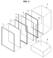
- FIG. 3 is an exploded view of a showcase, according to an exemplary embodiment.
- FIG. 4 is a cross-sectional view of a display module of a showcase, according to an exemplary embodiment.
- the showcase includes a display module 10 for displaying an image, a housing 20 coupled onto the rear side of the display module 10 to form a display space 20a that accommodates the object P, and a stand 30 coupled onto the bottom of the display module 10 and the housing 20 such that the display module 10 and the housing 20 supported on top of the stand 30.
- the display module 10 includes a display panel 11, a light guide plate 12 arranged behind the display panel 11 for guiding light, and two light sources 13 arranged toward the left and right sides of the light guide plate 12 for supplying light toward the left side and the right side of the light guide plate 12.
- a middle mold 14 arranged between the display panel 11 and the light guide plate 12 supports the display panel 11, a front chassis 15 maintains the display panel 11 installed in the middle mold 14 by supporting the outer side of a front portion of the display panel 11, and a rear chassis 16 coupled onto the rear portion of the middle mold 14 to supports the light guide plate 12 and the light source 13 therein.
- the display panel 11 may be formed of a liquid crystal panel in the form of a rectangular plate for receiving light supplied through the light guide plate 12 to display an image.
- the light guide plate 12 may be formed by a transparent material to pass light with a form of a rectangular plate corresponding to the display panel 11.
- FIG. 5 shows cross-sectional views of a display guide plate and a light source of a showcase, according to an exemplary embodiment.
- FIG. 6 is a cross-sectional view of a display guide plate and a light source of a showcase, according to an exemplary embodiment.
- the reflection patterns are formed by concaved prism grooves 12a having a triangular cross section, as shown in FIG. 5 .
- Each of the prism grooves 12a is formed such that the base is located opposite to the display panel 11 while the two oblique sides correspond to both sides of the light guide plate 12 on which the light sources 13 are arranged.
- each of the prism grooves 12a is formed as an isosceles triangle with the two oblique sides having the same length, which may be 50 ⁇ m or less. Furthermore, the vertical angle of the prism grooves 12a is formed to be in a range from 80 to 140 degrees, such that most of light entering into the light guide plate 12 through both sides of the light guide plate 12 may be reflected backward by the two oblique sides of each of the prism grooves 12a.
- the light sources 13 each include a substrate 13a in the form of a bar vertically extending to correspond to the left side or the right side of the light guide plate 12, and light emitting diodes (LEDs) 13b arranged on a side of the substrate 13a corresponding to a side of the light guide plate 12 for irradiating light toward the side of the light guide plate 12.
- the LEDs 13b are arranged at a distance from one another on the side of the substrate 13a.
- Each of the middle mold 14, the front chassis 15, and the rear chassis 16 has the form of a rectangular ring.
- the structure of the middle mold 14, the front chassis 15, and the rear chassis 16 supports the outer sides of the display panel 11 and light guide plate 12 while enabling the light that passes the light guide plate 12 to be delivered forward to the display panel 11 or backward to the housing 20.
- the housing 20 is in the form of the hull with an open front such that the interior of the housing 20 constitutes the display space 20a to accommodate the object P for display. Inside the display space 20a, there may be a white reflector having about 80% of reflectivity.
- the stand 30 is arranged under the display module 10 and housing 20 to provide support and contains various substrates 13a to drive the display module 10.
- the stand 30 allows the object P to be placed at a certain height or higher, thereby allowing a viewer to more conveniently view the object P in the display room 20a.
- the object P placed in the display space 20a light is generated from the LEDs 13b of the two light sources 13.
- the light generated from the LEDs 13b enters the light guide plate 12 through the left and right sides of the light guide plate 12. Most of the light entering the light guide plate 12 travels along the light guide plate 12 and is reflected backward by the oblique sides of the prism grooves 12a arranged on the front of the light guide plate 12. The reflected light is output backward through the rear of the light guide plate 12 and delivered into the display space 20a formed inside the housing 20, illuminating the display space 20a and the object P.
- the white reflector formed on the inner surfaces of the housing 20 that constitutes the display space 20a With the white reflector formed on the inner surfaces of the housing 20 that constitutes the display space 20a, the light is reflected at the inner wall of the display room 20 to enter back into the light guide plate 12 through the rear of the light guide plate 12. The light entering into the light guide plate 12 through the rear passes through the light guide plate 12 and is supplied to the display panel 11.
- the reflective structure of the showcase reduces the need for additional separate light sources for illuminating the object P, thereby allowing the showcase to have a thin compact profile.
- the size and arrangement are not limited thereto and it is also possible that some prism grooves 12a-1 located adjacent to the light sources 13 may be formed smaller in size than those 12a-1 located distant from the light sources 13, as shown in FIG. 6 . In other words, it is possible that the farther the prism grooves are located from the light source 13, the larger they are formed in size.
- the prism grooves 12a-1 formed of different sizes less reflection of light may occur at the prism grooves 12a-1 having a smaller size located in a region adjacent to the light source 13, which a relatively large amount of light reaches. On the contrary, more reflection of light may occur at the prism grooves 12a-1 having a larger size located in a region distant from the light source 13 that a relatively small amount of light reaches. Accordingly, light may be uniformly reflected by the prism grooves 12a-1 across the front of the light guide plate 12.
- FIG. 7 is a cross-sectional view of a display guide plate and a light source of a showcase, according to an exemplary embodiment.
- the prism grooves 12a-2 may be formed to have the same size, but the gaps between the prism grooves 12a-2 are relatively wide in the region adjacent to the light source 13 while being relatively narrow in the region distant from the light source 13. In other words, it is possible that the quantity of prism grooves increases with the distance from the light source.
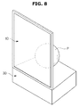
- FIG. 8 is a perspective view of a showcase, according to an exemplary embodiment. While the showcase includes the housing 20 to accommodate the object P in FIG. 7 , it is not limited thereto and is also possible to provide a showcase to allow the object P to be rested on the top of the stand 30 without a configuration corresponding to the housing, as shown in FIG. 8 .
- the showcase has the display panel 11 arranged in front of the light guide plate 12 for displaying an image in this embodiment
- the showcase is not limited thereto and may be configured without the display panel, which may instead be replaced by a transparent member, such as tempered glass.
- the two light sources 13 may be arranged toward the top and bottom sides of the light guide plate 12, or there may be four light sources respectively arranged toward the four sides, i.e., the top, bottom, left, and right sides of the light guide plate.
- the light source 13 includes the substrate 13a and the LEDs 13b in this embodiment, the light source 13 may employ point sources as LEDs or line sources that extend to correspond to the sides of the light guide plate.
- a showcase includes a light guide plate and a light source corresponding to a side of the light guide plate.
- Prism grooves are formed on the front of the light guide plate, by which most of the light entering into the light guide plate from the light source travels across a display space located behind and is reflected back in the forward direction, thereby enabling illumination of the display space with the light source used for a display panel, which eliminates a need for an additional light source to illuminate the object in the display space, and thus allows the showcase to have a thin profile.
Landscapes
- Physics & Mathematics (AREA)
- General Physics & Mathematics (AREA)
- Optics & Photonics (AREA)
- Freezers Or Refrigerated Showcases (AREA)
- Planar Illumination Modules (AREA)
- Devices That Are Associated With Refrigeration Equipment (AREA)
Applications Claiming Priority (2)
| Application Number | Priority Date | Filing Date | Title |
|---|---|---|---|
| US201562199373P | 2015-07-31 | 2015-07-31 | |
| KR1020150120221A KR20170015037A (ko) | 2015-07-31 | 2015-08-26 | 쇼 케이스 |
Publications (1)
| Publication Number | Publication Date |
|---|---|
| EP3123904A1 true EP3123904A1 (fr) | 2017-02-01 |
Family
ID=55646465
Family Applications (1)
| Application Number | Title | Priority Date | Filing Date |
|---|---|---|---|
| EP16163404.3A Withdrawn EP3123904A1 (fr) | 2015-07-31 | 2016-03-31 | Vitrine |
Country Status (3)
| Country | Link |
|---|---|
| US (1) | US20170031081A1 (fr) |
| EP (1) | EP3123904A1 (fr) |
| CN (1) | CN106388426A (fr) |
Families Citing this family (4)
| Publication number | Priority date | Publication date | Assignee | Title |
|---|---|---|---|---|
| KR102627962B1 (ko) * | 2016-12-12 | 2024-01-23 | 엘지전자 주식회사 | 냉장고 |
| US10496311B2 (en) | 2017-01-19 | 2019-12-03 | International Business Machines Corporation | Run-time instrumentation of guarded storage event processing |
| JP7369939B2 (ja) * | 2019-04-04 | 2023-10-27 | パナソニックIpマネジメント株式会社 | 画像表示装置 |
| US11747671B1 (en) * | 2022-08-31 | 2023-09-05 | Higgstec Inc. | Display device enabling external objects to be shown therein |
Citations (3)
| Publication number | Priority date | Publication date | Assignee | Title |
|---|---|---|---|---|
| US6123431A (en) * | 1997-03-19 | 2000-09-26 | Sanyo Electric Co., Ltd | Backlight apparatus and light guide plate |
| US20090135623A1 (en) * | 2007-11-27 | 2009-05-28 | Minebea Co., Ltd. | Spread illuminating apparatus |
| US20130343036A1 (en) * | 2011-04-26 | 2013-12-26 | IntelLED Corporation | Product lighting refrigeration door |
-
2016
- 2016-03-31 EP EP16163404.3A patent/EP3123904A1/fr not_active Withdrawn
- 2016-04-20 US US15/133,304 patent/US20170031081A1/en not_active Abandoned
- 2016-05-17 CN CN201610325875.8A patent/CN106388426A/zh active Pending
Patent Citations (3)
| Publication number | Priority date | Publication date | Assignee | Title |
|---|---|---|---|---|
| US6123431A (en) * | 1997-03-19 | 2000-09-26 | Sanyo Electric Co., Ltd | Backlight apparatus and light guide plate |
| US20090135623A1 (en) * | 2007-11-27 | 2009-05-28 | Minebea Co., Ltd. | Spread illuminating apparatus |
| US20130343036A1 (en) * | 2011-04-26 | 2013-12-26 | IntelLED Corporation | Product lighting refrigeration door |
Also Published As
| Publication number | Publication date |
|---|---|
| CN106388426A (zh) | 2017-02-15 |
| US20170031081A1 (en) | 2017-02-02 |
Similar Documents
| Publication | Publication Date | Title |
|---|---|---|
| US10401555B2 (en) | Light guide plate, display device and game machine | |
| EP3123904A1 (fr) | Vitrine | |
| KR102034890B1 (ko) | 곡면 디스플레이 장치 | |
| JP6776140B2 (ja) | 照明装置 | |
| JP6906968B2 (ja) | 照明装置 | |
| JP2007127871A (ja) | 立体表示装置 | |
| KR20160067447A (ko) | 디스플레이 장치 | |
| US9310547B2 (en) | Backlight assembly and a display device using the same | |
| JP2019061128A (ja) | 表示装置およびヘッドアップ表示装置 | |
| JP2012157554A (ja) | ショーケース | |
| JP5342398B2 (ja) | 照明具及び商品陳列棚 | |
| KR101404813B1 (ko) | 진열장 | |
| KR20110046137A (ko) | 백라이트 어셈블리 및 이를 갖는 표시장치 | |
| JP2010277901A5 (fr) | ||
| US20150131022A1 (en) | Multiple display monitor | |
| KR20170002077U (ko) | 물품 전시를 위한 조립식 케이스 | |
| KR20170015037A (ko) | 쇼 케이스 | |
| US9618675B2 (en) | Backlight assembly and display device having the same | |
| JP5255489B2 (ja) | 陳列棚用パネル体及び商品陳列棚 | |
| TW200951349A (en) | Surface light source device and liquid crystal display | |
| JP2017069021A (ja) | 照明装置 | |
| US20230026590A1 (en) | Illumination device, luminaire and refrigerator | |
| US11041987B2 (en) | Backlight unit with gap-retaining member and display device comprising same | |
| JP2018049772A (ja) | 展示用照明装置及びショーケース | |
| CN116889327A (zh) | 显示装置以及陈列柜 |
Legal Events
| Date | Code | Title | Description |
|---|---|---|---|
| PUAI | Public reference made under article 153(3) epc to a published international application that has entered the european phase |
Free format text: ORIGINAL CODE: 0009012 |
|
| AK | Designated contracting states |
Kind code of ref document: A1 Designated state(s): AL AT BE BG CH CY CZ DE DK EE ES FI FR GB GR HR HU IE IS IT LI LT LU LV MC MK MT NL NO PL PT RO RS SE SI SK SM TR |
|
| AX | Request for extension of the european patent |
Extension state: BA ME |
|
| STAA | Information on the status of an ep patent application or granted ep patent |
Free format text: STATUS: THE APPLICATION IS DEEMED TO BE WITHDRAWN |
|
| 18D | Application deemed to be withdrawn |
Effective date: 20170802 |