EP3123858B1 - Agricultural system - Google Patents
Agricultural system Download PDFInfo
- Publication number
- EP3123858B1 EP3123858B1 EP16181689.7A EP16181689A EP3123858B1 EP 3123858 B1 EP3123858 B1 EP 3123858B1 EP 16181689 A EP16181689 A EP 16181689A EP 3123858 B1 EP3123858 B1 EP 3123858B1
- Authority
- EP
- European Patent Office
- Prior art keywords
- baler
- steering
- crop
- tractor
- track
- Prior art date
- Legal status (The legal status is an assumption and is not a legal conclusion. Google has not performed a legal analysis and makes no representation as to the accuracy of the status listed.)
- Active
Links
Images
Classifications
-
- A—HUMAN NECESSITIES
- A01—AGRICULTURE; FORESTRY; ANIMAL HUSBANDRY; HUNTING; TRAPPING; FISHING
- A01B—SOIL WORKING IN AGRICULTURE OR FORESTRY; PARTS, DETAILS, OR ACCESSORIES OF AGRICULTURAL MACHINES OR IMPLEMENTS, IN GENERAL
- A01B69/00—Steering of agricultural machines or implements; Guiding agricultural machines or implements on a desired track
- A01B69/003—Steering or guiding of machines or implements pushed or pulled by or mounted on agricultural vehicles such as tractors, e.g. by lateral shifting of the towing connection
- A01B69/004—Steering or guiding of machines or implements pushed or pulled by or mounted on agricultural vehicles such as tractors, e.g. by lateral shifting of the towing connection automatic
-
- A—HUMAN NECESSITIES
- A01—AGRICULTURE; FORESTRY; ANIMAL HUSBANDRY; HUNTING; TRAPPING; FISHING
- A01F—PROCESSING OF HARVESTED PRODUCE; HAY OR STRAW PRESSES; DEVICES FOR STORING AGRICULTURAL OR HORTICULTURAL PRODUCE
- A01F15/00—Baling presses for straw, hay or the like
- A01F15/08—Details
-
- A—HUMAN NECESSITIES
- A01—AGRICULTURE; FORESTRY; ANIMAL HUSBANDRY; HUNTING; TRAPPING; FISHING
- A01B—SOIL WORKING IN AGRICULTURE OR FORESTRY; PARTS, DETAILS, OR ACCESSORIES OF AGRICULTURAL MACHINES OR IMPLEMENTS, IN GENERAL
- A01B69/00—Steering of agricultural machines or implements; Guiding agricultural machines or implements on a desired track
- A01B69/001—Steering by means of optical assistance, e.g. television cameras
-
- A—HUMAN NECESSITIES
- A01—AGRICULTURE; FORESTRY; ANIMAL HUSBANDRY; HUNTING; TRAPPING; FISHING
- A01D—HARVESTING; MOWING
- A01D87/00—Loaders for hay or like field crops
- A01D87/0023—Coupling arrangements between tractors, loaders or vehicles
-
- A—HUMAN NECESSITIES
- A01—AGRICULTURE; FORESTRY; ANIMAL HUSBANDRY; HUNTING; TRAPPING; FISHING
- A01D—HARVESTING; MOWING
- A01D89/00—Pick-ups for loaders, chaff-cutters, balers, field-threshers, or the like, i.e. attachments for picking-up hay or the like field crops
-
- A—HUMAN NECESSITIES
- A01—AGRICULTURE; FORESTRY; ANIMAL HUSBANDRY; HUNTING; TRAPPING; FISHING
- A01F—PROCESSING OF HARVESTED PRODUCE; HAY OR STRAW PRESSES; DEVICES FOR STORING AGRICULTURAL OR HORTICULTURAL PRODUCE
- A01F15/00—Baling presses for straw, hay or the like
-
- A—HUMAN NECESSITIES
- A01—AGRICULTURE; FORESTRY; ANIMAL HUSBANDRY; HUNTING; TRAPPING; FISHING
- A01F—PROCESSING OF HARVESTED PRODUCE; HAY OR STRAW PRESSES; DEVICES FOR STORING AGRICULTURAL OR HORTICULTURAL PRODUCE
- A01F15/00—Baling presses for straw, hay or the like
- A01F15/08—Details
- A01F15/0825—Regulating or controlling density or shape of the bale
- A01F15/0833—Regulating or controlling density or shape of the bale for round balers
Definitions
- the invention is directed to an agricultural system according to claim 1
- the agricultural system in question has the purpose of baling crop from a longitudinally extending crop swath in a field.
- the baler is being towed by a tow tractor via a draft hitch arrangement.
- Such an agricultural system is known for example from US 8,200,399 B2 .
- the draft hitch arrangement allows the baler pickup track to be slightly adjusted in lateral direction with respect to the tractor driving track in order to ensure that the baler is positioned optimally for picking up the crop from the crop swath in the field.
- the tractor comprises a sensor arrangement that detects geometrical information about the crop swath, such that the baler pickup track may be adjusted based on this information.
- US 4 433 533 A relates to a tractor drawn baler for the formation of large diameter cylindrical or round bales according to the preamble of claim 1.
- One disadvantage of the known agricultural system is the fact that not only the baler, but also the tractor is driving directly over the crop swath. This means that in the case of any misalignment of the tractor, at least part of the crop swath may be undesirably compressed. It may also occur that the tractor pushes part of the crop swath ahead of itself leading to a build-up of crop in front of the tractor which in the end has to be removed manually by the operator.
- baler pickup track describes the area on the field being swept over by the pickup device of the baler during the baling process.
- tractor driving track describes the track on the field defined by the outermost wheels or, if so, crawler tracks of the tractor during the baling process.
- tilt tractor is to be understood in a broad sense and includes all kind of vehicles suitable to tow a baler, including wheeled vehicles and crawler type vehicles.
- the solution according to the invention is based on the general idea that providing the tractor driving track laterally spaced from the crop swath allows the baler to autonomously align its baler pickup track onto a crop swath with low constructional effort.
- the reason for this is that due to the resulting lateral offset between the tractor and the baler the area in front of the baler is free of the tractor.
- the baler With this it is possible to provide the baler with a sensor arrangement which detection range is located in front of the baler. Based on the detection of the sensor arrangement the baler may align itself to the crop swath autonomously, which means that such alignment may be performed without any additional external sensor information, for example sensor information coming from the tow tractor.
- the baler is being towed by the tow tractor via a draft hitch arrangement, which draft hitch arrangement allows the baler pickup track to be laterally offset from the tractor driving track.
- the baler pickup track is aligned onto the crop swath for picking up crop and the tractor driving track is laterally spaced from the crop swath, such that the baling process is optimized and particularly, such that the baling process is not impaired by the tractor running over the crop swath.
- the baler For autonomously aligning the baler pickup track onto the crop swath, the baler comprises a steering system.
- This steering system comprises a sensor arrangement for detecting the cross profile of the crop swath at a location in front of the baler.
- the steering system further comprises a steering control and a steering drive, which steering control continuously aligns the baler pickup track onto the crop swath via the steering drive based on a predefined steering strategy and based on the detected profile.
- the sensor arrangement is an optical sensor arrangement, in particular a camera sensor arrangement.
- a simple and at the same time effective steering strategy is to center the baler pickup track to the crop swath (claim 2). This is particularly advantageous since for most balers it is important that the crop is being picked up from the crop swath evenly across the width of the pickup device of the baler such that the compression of the crop inside the baler is evenly performed accordingly. This ensures that the resulting bales are of on and the same, reproducible geometry.
- the hitch of the bailer may be deflected into different hitch positions in order to align the baler pickup track to the crop swath as proposed.
- the steering drive preferably comprises a hydraulic adjust cylinder which is in driving engagement with the hitch according to the especially preferred claim 5.
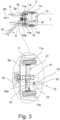
- the baler comprises a chassis with at least two steerable wheels according to claim 6.
- the wheels are steerable by the steering drive. While the deflection of the draft hitch arrangement by the steering drive is easy to realize in constructional view, steering the wheels of the baler by the steering drive leads to a particularly quick reaction on any drive movement of the steering drive.
- the steering system of the baler comprises a communication module to communicate with a drive control of the tow tractor.
- a communication module to communicate with a drive control of the tow tractor.
- the purpose of the proposed agricultural system 1 is to produce bales 2 using a baler 3 by picking up and compressing crop 4 from a crop swath 5 in a field.
- Such a crop swath 5 is being produced in a mowing process which precedes the baling process.
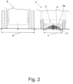
- the crop swath 5 normally extends along a line and comprises a certain cross profile.
- the cross profile goes back on the distribution of crop 4 across the crop swath 5. It is normally of overall convex shape as shown in fig. 2 .
- the baler 3 comprises a pickup device 3a picking up crop 4 from the field along a baler pickup track 7.
- the picked up crop 4 is then processed into bales 2 as is generally known.
- the bales 2 may be of different design such as cylindrical, cubical or the like. It is mostly of particular importance that the baler 3 picks up the crop 4 as evenly as possible across the width of the pickup device 3a of the baler 3 in order to guarantee the production of bales 2 with one and the same geometry.
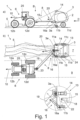
- the proposed agricultural system 1 also comprises a tow tractor 6, which tows the baler 3 via a draft hitch arrangement 8 of the baler 3.
- baler pickup track 7 may be laterally offset from the tractor driving track 9 with respect to the tractor driving direction 10. With this it is first of all possible, as shown in fig. 1b , that during baling the baler pickup track 7 is aligned to the crop swath 5 for picking up crop 4. With this alignment the above noted reproducibility regarding the generation of bales 2 can be guaranteed.
- the draft hitch arrangement 8 allows the tractor driving track 9 during baling to be laterally spaced from the crop swath 5 with respect to the tractor driving direction 10.
- fig. 1b shows that with this laterally spacing of the tow tractor 6 the crop swath 5 is never being driven over by the tow tractor 6 which prevents an undesired compression of the crop swath 5.
- the baler 3 here and preferably comprises wheels 11a-d for moving along with the towtractor 6.
- the tow tractor 6 normally comprises wheels 12a-d as well.
- the tow tractor 6 may just as well be of crawler type as noted above.
- the baler 3 itself comprises a steering system 13 for autonomously aligning the baler pickup track 7 onto the crop swath 5. This means that the baler 3 aligns itself to the crop swath 5 solely by its own steering system 13. This autonomous approach to steering the baler 3 makes it possible to the baler 3 to be combined with any kind of tow tractor 6.
- the steering system 13 comprises a sensor arrangement 14 for detecting geometrical information about the above noted cross profile 5a of the crop swath 5 at a location in front of the baler 3.
- This information is called “cross profile information” in the following.
- the expression “in front of” is to be understood with respect to the baler driving direction 20.
- the detection of cross profile information 5a may be performed in various levels of abstraction.
- the sensor arrangement 14 for example detects the outer contour of the crop swath 5 as the cross profile information 5a.
- the sensor arrangement 14 only detects the width of the crop swath 5 in a direction transverse to the longitudinal extension of the crop swath 5 as the cross profile information 5a.
- the steering system 13 also comprises a steering control 15 and a steering drive 16, as shown in fig. 1b as well.
- the steering control 15 continuously aligns the baler pickup track 7 onto the crop swath 5 via the steering drive 16 based on a predefined steering strategy and based on the detected cross profile information 5a.
- the alignment of the baler pickup track 7 to the crop swath 5 is being performed by a continuous adjustment of the steering of the baler 3 by the steering drive 16, while the baler 3 is being towed by the tow tractor 6.
- the sensor arrangement 14 of the baler 3 is an optical sensor arrangement, in particular a camera arrangement. It is further preferred that the camera arrangement is realized as a 3D camera arrangement. Other kinds of sensors may be applied for the sensor arrangement 14. Examples are laser scanners, ultrasonic sensors or the like.
- the sensor arrangement 14 comprises a camera. From the camera picture the outer contour of the crop swath 5 is being extracted as the cross profile information 5a, which the the alignment of the baler pickup track 7 onto the crop swath 5 is based on.
- the steering strategy is to center the baler pickup track 7 to the crop swath 5. Such centering is shown in fig. 2 as an example.
- the center of area of the crop swath 5 is calculated, which is depicted with reference numeral 17. According to this steering strategy the baler pickup track 7 is then being aligned exactly to the calculated center of area 17.
- the steering system 13 of the baler 3 comprises a memory 18 in which a number of steering strategies are stored for selection by the user. Accordingly it is possible for the user to choose one steering strategy out of a group of steering strategies, which group may preferably be extended if necessary.
- the draft hitch arrangement 8 of the baler 3 comprises a hitch 19 that may laterally be deflected with respect to the baler driving direction 20 by the steering drive 16 into different hitch positions. It becomes clear from fig. 1b that such deflection causes the baler 3 to change its orientation with respect to the tow tractor 6, which in the end leads to changing the baler driving direction 20. This may easily be realized by providing the steering drive 16 with at least one hydraulic adjust cylinder 16a which is in driving engagement with the hitch 19 of the draft hitch arrangement 8.
- baler 3 in order to reduce the reaction time between a drive movement of the steering drive 16 and a change in baler driving direction 20, it may be advantageous to provide the baler 3 with a chassis 21 with at least two steerable wheels 11a,b, which wheels 11a,b are steerable by the steering drive 16.
- the baler 3 may be advantageous to establish a communication between the baler 3 and the tow tractor 6 as will be described.
- An example for this is to provide the possibility for the baler 3 to adapt the tractor driving direction 10 in order to ensure that the baler 3 can actually perform its alignment in accordance with the selected steering strategy.
- the steering system 13 of the baler 3 comprises a communication module 22 to communicate with a drive control 23 of the tow tractor 6.
- This communication module 22 may establish a wire based communication with the drive control 23 of the tow tractor 6.
- the communication module 22 establishes a wireless communication with the drive control 23.
- the steering system 13 of the baler 3 controls the steering of the tow tractor 6 via the communication module 22. Further preferably, at least partly during baling, all steering actions of the tow tractor 6 are being remotely controlled by the steering system 13 of the baler 3 via the communication module 22.
- an out of bounds condition is defined in which the steering strategy requires a steering adjustment of the tow tractor 6 and that the steering system 13 of the baler 3 controls the steering adjustment of the tow tractor 6 via the communication module 22.
- the steering system 13 of the baler 3 only influences the steering of the tow tractor 6, if the above noted out of bounds condition is fulfilled.
- the communication module 22 may be used in different ways during the baling process.
- the communication module 22 is designed to transmit at least one of a hitch position, a request of steering adjustment of the tow tractor 6 and a user information. Other examples are possible.
- the communication module 22 may also be designed to receive information from the tow tractor 6.
- the communication module 22 is designed to receive at least one of a user input, a request to start autonomously aligning the baler pickup track 7, a request to stop autonomously aligning the baler pickup track 7, and a request to position the hitch 19 into a certain hitch position.
- the baler 3 comprises an input/output module 24 to interact with the user.
- the communication module 22 may allow to use an input/output module 25 of the tow tractor 6 in order to input or output baler relevant information, in particular to select an above noted steering strategy.
Landscapes
- Life Sciences & Earth Sciences (AREA)
- Environmental Sciences (AREA)
- Engineering & Computer Science (AREA)
- Mechanical Engineering (AREA)
- Soil Sciences (AREA)
- Guiding Agricultural Machines (AREA)
Description
- The invention is directed to an agricultural system according to
claim 1 - The agricultural system in question has the purpose of baling crop from a longitudinally extending crop swath in a field. The baler is being towed by a tow tractor via a draft hitch arrangement. Such an agricultural system is known for example from
US 8,200,399 B2 . - In the above noted known agricultural system the draft hitch arrangement allows the baler pickup track to be slightly adjusted in lateral direction with respect to the tractor driving track in order to ensure that the baler is positioned optimally for picking up the crop from the crop swath in the field. For this the tractor comprises a sensor arrangement that detects geometrical information about the crop swath, such that the baler pickup track may be adjusted based on this information.
US 4 433 533 A relates to a tractor drawn baler for the formation of large diameter cylindrical or round bales according to the preamble ofclaim 1. - One disadvantage of the known agricultural system is the fact that not only the baler, but also the tractor is driving directly over the crop swath. This means that in the case of any misalignment of the tractor, at least part of the crop swath may be undesirably compressed. It may also occur that the tractor pushes part of the crop swath ahead of itself leading to a build-up of crop in front of the tractor which in the end has to be removed manually by the operator.
- Both above noted disadvantages of the known agricultural system lead to a decrease of efficiency in the baling process.
- It is therefore an object of the invention to improve the known agricultural system such that the efficiency of the baling process is increased with low constructional effort.
- The above noted object is solved by an agricultural system according to
claim 1. - The proposed solution is generally based on the baler pickup track and the tractor driving track being laterally offset from each other with respect to the tractor driving direction. The expression "baler pickup track" describes the area on the field being swept over by the pickup device of the baler during the baling process. The expression "tractor driving track" describes the track on the field defined by the outermost wheels or, if so, crawler tracks of the tractor during the baling process. The expression "tow tractor" is to be understood in a broad sense and includes all kind of vehicles suitable to tow a baler, including wheeled vehicles and crawler type vehicles.
- The solution according to the invention is based on the general idea that providing the tractor driving track laterally spaced from the crop swath allows the baler to autonomously align its baler pickup track onto a crop swath with low constructional effort. The reason for this is that due to the resulting lateral offset between the tractor and the baler the area in front of the baler is free of the tractor. With this it is possible to provide the baler with a sensor arrangement which detection range is located in front of the baler. Based on the detection of the sensor arrangement the baler may align itself to the crop swath autonomously, which means that such alignment may be performed without any additional external sensor information, for example sensor information coming from the tow tractor.
- in detail it is proposed that the baler is being towed by the tow tractor via a draft hitch arrangement, which draft hitch arrangement allows the baler pickup track to be laterally offset from the tractor driving track. During baling, the baler pickup track is aligned onto the crop swath for picking up crop and the tractor driving track is laterally spaced from the crop swath, such that the baling process is optimized and particularly, such that the baling process is not impaired by the tractor running over the crop swath.
- For autonomously aligning the baler pickup track onto the crop swath, the baler comprises a steering system. This steering system comprises a sensor arrangement for detecting the cross profile of the crop swath at a location in front of the baler. The steering system further comprises a steering control and a steering drive, which steering control continuously aligns the baler pickup track onto the crop swath via the steering drive based on a predefined steering strategy and based on the detected profile.
- For realizing the sensor arrangement a number of advantages solutions are possible. Preferably the sensor arrangement is an optical sensor arrangement, in particular a camera sensor arrangement.
- According to the preferred solutions of
claims - According to the preferred embodiment of claim 4 the hitch of the bailer may be deflected into different hitch positions in order to align the baler pickup track to the crop swath as proposed. For this the steering drive preferably comprises a hydraulic adjust cylinder which is in driving engagement with the hitch according to the especially preferred
claim 5. - As an alternative it is possible that the baler comprises a chassis with at least two steerable wheels according to
claim 6. Here the wheels are steerable by the steering drive. While the deflection of the draft hitch arrangement by the steering drive is easy to realize in constructional view, steering the wheels of the baler by the steering drive leads to a particularly quick reaction on any drive movement of the steering drive. - In the preferred solutions according to
claims 7 to 11 the steering system of the baler comprises a communication module to communicate with a drive control of the tow tractor. This allows, for example, that the baler controls the steering of the tow tractor (claim 8), in particular if a steering adjustment of the tow tractor is required for the baler to autonomously align its baler pickup track to the crop swath (claim 9). This prevents the agricultural system to have to stop if the baler cannot perform the alignment due to the tractor driving track drifting too far away from the crop swath. - In the following the invention will be described based on examples with reference to the drawings. In the drawings show
- Fig. 1
- an agricultural system according to the invention a) in side view and b) in top view,
- Fig. 2
- the agricultural system according to
fig. 1 in view II and - Fig. 3
- the baler of the agricultural system of
fig. 1 with an alternative steering system. - The purpose of the proposed
agricultural system 1 is to producebales 2 using abaler 3 by picking up and compressing crop 4 from acrop swath 5 in a field. - Such a
crop swath 5 is being produced in a mowing process which precedes the baling process. Thecrop swath 5 normally extends along a line and comprises a certain cross profile. The cross profile goes back on the distribution of crop 4 across thecrop swath 5. It is normally of overall convex shape as shown infig. 2 . - The
baler 3 comprises apickup device 3a picking up crop 4 from the field along abaler pickup track 7. The picked up crop 4 is then processed intobales 2 as is generally known. Thebales 2 may be of different design such as cylindrical, cubical or the like. It is mostly of particular importance that thebaler 3 picks up the crop 4 as evenly as possible across the width of thepickup device 3a of thebaler 3 in order to guarantee the production ofbales 2 with one and the same geometry. - The proposed
agricultural system 1 also comprises atow tractor 6, which tows thebaler 3 via adraft hitch arrangement 8 of thebaler 3. - One specialty about the proposed
draft hitch arrangement 8 is its construction such that thebaler pickup track 7 may be laterally offset from thetractor driving track 9 with respect to thetractor driving direction 10. With this it is first of all possible, as shown infig. 1b , that during baling thebaler pickup track 7 is aligned to thecrop swath 5 for picking up crop 4. With this alignment the above noted reproducibility regarding the generation ofbales 2 can be guaranteed. At the same time thedraft hitch arrangement 8 allows thetractor driving track 9 during baling to be laterally spaced from thecrop swath 5 with respect to thetractor driving direction 10.fig. 1b shows that with this laterally spacing of thetow tractor 6 thecrop swath 5 is never being driven over by thetow tractor 6 which prevents an undesired compression of thecrop swath 5. - It is to be understood that the
baler 3 here and preferably compriseswheels 11a-d for moving along with thetowtractor 6. Thetow tractor 6 normally compriseswheels 12a-d as well. However, thetow tractor 6 may just as well be of crawler type as noted above. - The
baler 3 itself comprises asteering system 13 for autonomously aligning thebaler pickup track 7 onto thecrop swath 5. This means that thebaler 3 aligns itself to thecrop swath 5 solely by itsown steering system 13. This autonomous approach to steering thebaler 3 makes it possible to thebaler 3 to be combined with any kind oftow tractor 6. - The
steering system 13 comprises asensor arrangement 14 for detecting geometrical information about the abovenoted cross profile 5a of thecrop swath 5 at a location in front of thebaler 3. This information is called "cross profile information" in the following. The expression "in front of" is to be understood with respect to thebaler driving direction 20. The detection ofcross profile information 5a may be performed in various levels of abstraction. In one embodiment, thesensor arrangement 14 for example detects the outer contour of thecrop swath 5 as thecross profile information 5a. In another embodiment, thesensor arrangement 14 only detects the width of thecrop swath 5 in a direction transverse to the longitudinal extension of thecrop swath 5 as thecross profile information 5a. - The
steering system 13 also comprises asteering control 15 and asteering drive 16, as shown infig. 1b as well. During baling, thesteering control 15 continuously aligns thebaler pickup track 7 onto thecrop swath 5 via thesteering drive 16 based on a predefined steering strategy and based on the detectedcross profile information 5a. In other words, the alignment of thebaler pickup track 7 to thecrop swath 5 is being performed by a continuous adjustment of the steering of thebaler 3 by thesteering drive 16, while thebaler 3 is being towed by thetow tractor 6. - It becomes apparent from
fig. 1 that the location of thebaler 3 and thetow tractor 6 laterally offset to each other leads to the area in front of thebaler 3 to be completely free of thetow tractor 6, such that thesensor arrangement 14 of thebaler 3 may detect the geometrical profile of thecrop swath 5 without being impaired by thetow tractor 6. - Preferably, the
sensor arrangement 14 of thebaler 3 is an optical sensor arrangement, in particular a camera arrangement. It is further preferred that the camera arrangement is realized as a 3D camera arrangement. Other kinds of sensors may be applied for thesensor arrangement 14. Examples are laser scanners, ultrasonic sensors or the like. In the shown embodiments thesensor arrangement 14 comprises a camera. From the camera picture the outer contour of thecrop swath 5 is being extracted as thecross profile information 5a, which the the alignment of thebaler pickup track 7 onto thecrop swath 5 is based on. - Depending on the type of
baler 3 and the type ofcrop swath 5 different steering strategies may be advantageous. Here and preferably the steering strategy is to center thebaler pickup track 7 to thecrop swath 5. Such centering is shown infig. 2 as an example. Here and preferably, first the center of area of thecrop swath 5 is calculated, which is depicted withreference numeral 17. According to this steering strategy thebaler pickup track 7 is then being aligned exactly to the calculated center ofarea 17. - As an alternative steering strategy, especially if the
crop swath 5 is of uneven composition along its extension, it is proposed to optimize the alignment of thepickup track 7 onto thecrop swath 5 such that during baling the pickup rate of crop 4 is evenly distributed across thepickup device 7. This may be achieved, for example, by cyclically switching between two baler pickup tracks, which two baler pickup tracks are located oppositely off-center in view of the cross profile of 5a of thecrop swath 5. According to this steering strategy thebaler 3 is being toggled between the two baler pickup tracks in order to achieve an even loading process of thebaler 3. - Preferably, the
steering system 13 of thebaler 3 comprises amemory 18 in which a number of steering strategies are stored for selection by the user. Accordingly it is possible for the user to choose one steering strategy out of a group of steering strategies, which group may preferably be extended if necessary. - There are various possibilities to realize the steering of the
baler 3 in constructional view. - in the preferred embodiment shown in
fig. 1b thedraft hitch arrangement 8 of thebaler 3 comprises ahitch 19 that may laterally be deflected with respect to thebaler driving direction 20 by thesteering drive 16 into different hitch positions. It becomes clear fromfig. 1b that such deflection causes thebaler 3 to change its orientation with respect to thetow tractor 6, which in the end leads to changing thebaler driving direction 20. This may easily be realized by providing thesteering drive 16 with at least one hydraulic adjustcylinder 16a which is in driving engagement with thehitch 19 of thedraft hitch arrangement 8. - As an alternative, in order to reduce the reaction time between a drive movement of the
steering drive 16 and a change inbaler driving direction 20, it may be advantageous to provide thebaler 3 with achassis 21 with at least twosteerable wheels 11a,b, whichwheels 11a,b are steerable by thesteering drive 16. - Despite it being possible for the
baler 3 to generally work as a stand-alone system in terms of control, in particular without the necessity to communicate with thetow tractor 6, it may be advantageous to establish a communication between thebaler 3 and thetow tractor 6 as will be described. An example for this is to provide the possibility for thebaler 3 to adapt thetractor driving direction 10 in order to ensure that thebaler 3 can actually perform its alignment in accordance with the selected steering strategy. Therefore, preferably, thesteering system 13 of thebaler 3 comprises acommunication module 22 to communicate with adrive control 23 of thetow tractor 6. Thiscommunication module 22 may establish a wire based communication with thedrive control 23 of thetow tractor 6. However, here and preferably, thecommunication module 22 establishes a wireless communication with thedrive control 23. - As noted above, it is especially preferred that the
steering system 13 of thebaler 3 controls the steering of thetow tractor 6 via thecommunication module 22. Further preferably, at least partly during baling, all steering actions of thetow tractor 6 are being remotely controlled by thesteering system 13 of thebaler 3 via thecommunication module 22. - However, in order to reduce the transmission of data it is preferred that an out of bounds condition is defined in which the steering strategy requires a steering adjustment of the
tow tractor 6 and that thesteering system 13 of thebaler 3 controls the steering adjustment of thetow tractor 6 via thecommunication module 22. This means that thesteering system 13 of thebaler 3 only influences the steering of thetow tractor 6, if the above noted out of bounds condition is fulfilled. - The
communication module 22 may be used in different ways during the baling process. For example, thecommunication module 22 is designed to transmit at least one of a hitch position, a request of steering adjustment of thetow tractor 6 and a user information. Other examples are possible. - The
communication module 22 may also be designed to receive information from thetow tractor 6. Preferably, thecommunication module 22 is designed to receive at least one of a user input, a request to start autonomously aligning thebaler pickup track 7, a request to stop autonomously aligning thebaler pickup track 7, and a request to position thehitch 19 into a certain hitch position. - Preferably the
baler 3 comprises an input/output module 24 to interact with the user. In particular it may be possible to select an above noted steering strategy via the input/output module 24. In addition or as an alternative thecommunication module 22 may allow to use an input/output module 25 of thetow tractor 6 in order to input or output baler relevant information, in particular to select an above noted steering strategy. -
- 1
- agricultural system
- 2
- bales
- 3
- baler
- 3a
- pickup device
- 4
- crop
- 5
- crop swath
- 5a
- cross profile of crop swath
- 6
- tow tractor
- 7
- baler pickup track
- 8
- draft hitch arrangement
- 9
- tractor driving track
- 10
- tractor driving direction
- 11a-d
- wheel baler
- 12a-d
- wheel tractor
- 13
- baler steering system
- 14
- sensor arrangement
- 15
- baler steering control
- 16
- baler steering drive
- 16a
- cylinder of steering drive
- 17
- center of area
- 18
- memory
- 19
- hitch of draft hitch arrangement
- 20
- baler driving direction
- 21
- chassis baler
- 22
- communication module
- 23
- drive control tractor
- 24
- input/output-module baler
- 25
- input/output-module tractor
Claims (12)
- Agricultural system comprising a baler (3) for picking up and compressing crop (4) from a crop swath (5) in a field and comprising a tow tractor (6), wherein the baler (3) comprises a pickup device (3a) picking up crop (4) from the field along a baler pickup track (7), wherein the baler (3) is being towed by the tow tractor (6) via a draft hitch arrangement (8), which draft hitch arrangement (8) is constructed such that the baler pickup track (7) is laterally offset from a tractor driving track (9) with respect to a tractor driving direction (10), wherein, during baling, the baler pickup track (7) is aligned onto the crop swath (5) for picking up crop (4) and the tractor driving track (9) is laterally spaced from the crop swath (5) with respect to the tractor driving direction (10), wherein the baler (3) comprises a steering system (13) for autonomously aligning the baler pickup track (7) onto the crop swath (5), characterized in that the baler steering system (13) comprises a sensor arrangement (14) for detecting cross profile information (5a) of the crop swath (5) with respect to a longitudinal extension of the crop swath (5) at a location in front of the baler (3), wherein the baler steering system (13) comprises a baler steering control (15) and abaler steering drive (16), which baler steering control (15), during baling, continuously aligns the baler pickup track (7) onto the crop swath (5) via the baler steering drive (16) based on a predefined steering strategy and based on the cross profile information (5a) of the crop swath (5) detected by the sensor arrangement (14), wherein the baler steering system (13) comprises a memory (18) in which a number of steering strategies are stored for selection by a user.
- Agricultural system according to claim 1, characterized in that one steering strategy is to center the baler pickup track (7) to the crop swath (5).
- Agricultural system according to claim 1 or 2, characterized in that one steering strategy is to optimize the alignment of the pickup track (7) onto the crop swath (5) such that during baling the pickup rate of crop (4) is evenly distributed across the pickup device (7).
- Agricultural system according to any one of the preceding claims, characterized in that the draft hitch arrangement (8) comprises a hitch (19) that may laterally be deflected with respect to the baler driving direction (20) by the baler steering drive (16) into different hitch positions.
- Agricultural system according to any one of the preceding claims, characterized in that the baler steering drive (16) comprises at least one hydraulic adjust cylinder (16a) which is in driving engagement with the hitch (19).
- Agricultural system according to any one of the preceding claims, characterized in that the baler (3) comprises a chassis (21) with at least two steerable wheels (11a, 11b), which wheels (11a, 11b) are steerable by the baler steering drive (16).
- Agricultural system according to any one of the preceding claims, characterized in that the baler steering system (13) comprises a communication module (22) to communicate with a drive control (23) of the tow tractor (6).
- Agricultural system according to claim 7, characterized in that the baler steering system (13) controls the steering of the tow tractor (6) via the communication module (22).
- Agricultural system according to claim 7 or 8 , characterized in that an out of bounds condition is defined in which the steering strategy requires a steering adjustment of the tow tractor (6) and that the baler steering system (13) controls the steering adjustment of the tow tractor (6) via the communication module (22).
- Agricultural system according to any one of the claims 7 to 9, characterized in that the communication module (22) is designed to transmit at least one of hitch position, a request of steering adjustment of the tow tractor (6) and a user information.
- Agricultural system according to any one of the claims 7 to 10, characterized in that the communication module (22) is designed to receive at least one of a user input, a request to start autonomously aligning the baler pickup track (7), a request to stop autonomously aligning the baler pickup track (7), and a request to position the hitch (19) into a certain hitch position.
- Agricultural system according to any one of the preceding claims, characterized in that the baler (3) comprises an input/output module (24) to interact with the user.
Applications Claiming Priority (1)
| Application Number | Priority Date | Filing Date | Title |
|---|---|---|---|
| US14/812,156 US9706697B2 (en) | 2015-07-29 | 2015-07-29 | Agricultural system with a baler and tow tractor and a steering arrangement by which the baler is steered autonomously |
Publications (2)
| Publication Number | Publication Date |
|---|---|
| EP3123858A1 EP3123858A1 (en) | 2017-02-01 |
| EP3123858B1 true EP3123858B1 (en) | 2023-09-20 |
Family
ID=56800135
Family Applications (1)
| Application Number | Title | Priority Date | Filing Date |
|---|---|---|---|
| EP16181689.7A Active EP3123858B1 (en) | 2015-07-29 | 2016-07-28 | Agricultural system |
Country Status (2)
| Country | Link |
|---|---|
| US (1) | US9706697B2 (en) |
| EP (1) | EP3123858B1 (en) |
Cited By (1)
| Publication number | Priority date | Publication date | Assignee | Title |
|---|---|---|---|---|
| EP4635290A1 (en) | 2024-04-16 | 2025-10-22 | Kverneland Group Ravenna S.r.l. | A method of forming a bale by a baler, an agricultural system, and a baler |
Families Citing this family (25)
| Publication number | Priority date | Publication date | Assignee | Title |
|---|---|---|---|---|
| EP3008985B1 (en) * | 2014-10-15 | 2017-08-09 | Kverneland Group Ravenna S.r.l. | Towing apparatus for agricultural machines, of the type of balers, round balers and the like |
| CA3112021C (en) * | 2016-05-19 | 2024-10-08 | Vermeer Manufacturing Company | Autonomous bale moving system and method |
| JP6871569B2 (en) * | 2017-03-23 | 2021-05-12 | 株式会社タカキタ | Wrap machine |
| BE1024834B1 (en) * | 2017-05-09 | 2018-07-13 | Cnh Industrial Belgium Nv | AGRICULTURAL SYSTEM |
| BE1024801B1 (en) * | 2017-05-09 | 2018-07-03 | Cnh Industrial Belgium Nv | IMPROVEMENTS IN OR RELATING TO TRACTOR / TRAILER COMBINATIONS |
| BE1024928B1 (en) * | 2017-05-09 | 2018-08-13 | Cnh Industrial Belgium Nv | IMPROVEMENTS IN OR RELATING TO TRACTOR / BALER PRESS COMBINATIONS |
| CN107295862A (en) * | 2017-08-14 | 2017-10-27 | 宁夏新大众机械有限公司 | A kind of careless collecting machine of square bale |
| CN107960207B (en) * | 2017-11-28 | 2019-12-06 | 阜阳市四方秸秆能源利用有限公司 | Straw collection device |
| IT201800010737A1 (en) * | 2018-11-30 | 2020-05-30 | Volta Robots S R L | METHOD OF CONTROL OF A SOIL PROCESSING MEANS ON THE BASIS OF IMPROVED IMAGE PROCESSING AND RELATED SYSTEM |
| DE102019201333A1 (en) | 2019-02-01 | 2020-08-06 | Deere & Company | Agricultural implement, drawbar device and tractor-implement combination |
| DE102019201337A1 (en) | 2019-02-01 | 2020-08-06 | Deere & Company | Agricultural implement, drawbar device and tractor-implement combination |
| US11684015B2 (en) | 2019-08-07 | 2023-06-27 | Cnh Industrial America Llc | Agricultural baling system with controlled tractor steering to balance bale density |
| US11666002B2 (en) | 2019-12-16 | 2023-06-06 | Cnh Industrial America Llc | Electrically driven agricultural baler |
| EP3959964B1 (en) * | 2020-08-27 | 2026-03-04 | AGCO Corporation | Automated baler pickup control based on windrow detection |
| DE102020132332A1 (en) | 2020-12-04 | 2022-06-09 | 365Farmnet Group Kgaa Mbh & Co Kg | Method for controlling a cloud-based agricultural database system |
| JP7365103B2 (en) * | 2020-12-24 | 2023-10-19 | 株式会社クボタ | Farming support system, location information generation method, computer program and processing device |
| US12082515B2 (en) * | 2021-03-12 | 2024-09-10 | Deere & Company | Methods for controlling articulating tongue arrangements utilized in towing agricultural implements |
| US12048259B2 (en) | 2021-03-12 | 2024-07-30 | Deere & Company | Articulating tongue arrangements for towed agricultural implements |
| EP4104670B1 (en) * | 2021-06-16 | 2025-03-12 | CNH Industrial Belgium N.V. | Monitoring bale shape |
| US12510893B2 (en) | 2022-05-17 | 2025-12-30 | Cnh Industrial America Llc | Visual guidance system with machine learning for agricultural machines |
| US20240065166A1 (en) * | 2022-08-29 | 2024-02-29 | Deere & Company | Rake implement with moveable tongue |
| CA219269S (en) | 2022-09-16 | 2024-06-13 | Claas Kgaa Mbh | Baler |
| USD1069851S1 (en) | 2022-12-02 | 2025-04-08 | Vermeer Manufacturing Company | Bale mover |
| US12464968B2 (en) | 2022-12-14 | 2025-11-11 | Cnh Industrial America Llc | Position monitoring system for agricultural system |
| US20250287856A1 (en) * | 2024-03-18 | 2025-09-18 | Raven Industries, Inc. | Autonomous articulating agricultural implement controllers and methods for same |
Family Cites Families (27)
| Publication number | Priority date | Publication date | Assignee | Title |
|---|---|---|---|---|
| FR2254265A2 (en) * | 1973-08-14 | 1975-07-11 | Fahr Ag Maschf | Combine harvester automatic guidance system - has sensor head near rear steering wheel, pickups, travel stops, and program changeover |
| US4065914A (en) * | 1976-03-15 | 1978-01-03 | International Harvester Company | Offset baler with steerable control |
| US4224867A (en) * | 1979-03-21 | 1980-09-30 | Hesston Corporation | Crop loading monitor for rotary balers |
| DE2912715C2 (en) * | 1979-03-30 | 1983-08-04 | Klöckner-Humboldt-Deutz AG Zweigniederlassung Fahr, 7702 Gottmadingen | Pulled harvester |
| US4517795A (en) * | 1979-11-28 | 1985-05-21 | Deere & Company | Bale-shape gauge for baler for forming cylindrical bales |
| DE3166404D1 (en) * | 1981-03-25 | 1984-11-08 | Deere John | Baling press |
| US4702066A (en) * | 1986-07-25 | 1987-10-27 | Vermeer Manufacturing Company | Round baler with automatic steering system |
| US4748802A (en) * | 1987-05-07 | 1988-06-07 | New Holland Inc. | Apparatus and method for monitoring bale shape in round balers |
| US4850271A (en) * | 1987-09-29 | 1989-07-25 | Hesston Corporation | Round baler having simulated bale size and shape indicator |
| US5165332A (en) * | 1990-01-11 | 1992-11-24 | Gehl Company | Bale density monitoring apparatus and method |
| US5408817A (en) * | 1993-07-12 | 1995-04-25 | New Holland North America, Inc. | Bale shape monitoring method for round balers |
| US5444969A (en) * | 1993-07-12 | 1995-08-29 | New Holland North America, Inc. | Round baler apparatus for monitoring bale shape |
| DE19508941A1 (en) * | 1995-03-13 | 1996-09-19 | Claas Ohg | Locating device |
| DE19508942A1 (en) * | 1995-03-13 | 1996-09-19 | Claas Ohg | Reflex locator |
| US5615544A (en) * | 1996-02-13 | 1997-04-01 | New Holland North America, Inc. | System for monitoring the shape of round bales |
| US6000206A (en) * | 1996-10-04 | 1999-12-14 | Hay & Forage Industries | In-line rectangular baler selectively operable in centered or off-set positions |
| DE19719939A1 (en) * | 1997-05-13 | 1998-11-19 | Claas Ohg | Automatically steerable harvesting machine |
| US6199355B1 (en) * | 1998-03-09 | 2001-03-13 | New Holland North America, Inc. | Control apparatus for rotatable gearbox on crop harvester |
| DE10204702A1 (en) * | 2002-02-05 | 2003-08-14 | Claas Selbstfahr Erntemasch | Location system on self-propelled agricultural machines |
| UA91239C2 (en) | 2005-09-14 | 2010-07-12 | АГРОКОМ Фервальтунгс ГмбХ | Method for controlling operation of pickup baler and pickup baler |
| US7404355B2 (en) | 2006-01-31 | 2008-07-29 | Deere & Company | Tractor and baler combination with automatic baling and tractor halt control |
| DE102009002439A1 (en) | 2008-11-19 | 2010-05-20 | Deere & Company, Moline | Arrangement and method for wrapping a bale |
| US8234033B2 (en) * | 2009-06-12 | 2012-07-31 | Cnh America Llc | Guidance method for agricultural vehicle |
| DE102009047585A1 (en) * | 2009-12-07 | 2011-06-09 | Deere & Company, Moline | Combination of a towing vehicle and a device |
| DE102010041885A1 (en) * | 2010-10-01 | 2012-04-05 | Deere & Company | Combination of a towing vehicle and a device |
| US9791863B2 (en) * | 2013-11-11 | 2017-10-17 | Deere & Company | Location-based material gathering |
| DE102014105820A1 (en) * | 2014-04-25 | 2015-10-29 | Usines Claas France S.A.S. | Combination of a towing vehicle and a harvester pulled by it |
-
2015
- 2015-07-29 US US14/812,156 patent/US9706697B2/en active Active
-
2016
- 2016-07-28 EP EP16181689.7A patent/EP3123858B1/en active Active
Cited By (2)
| Publication number | Priority date | Publication date | Assignee | Title |
|---|---|---|---|---|
| EP4635290A1 (en) | 2024-04-16 | 2025-10-22 | Kverneland Group Ravenna S.r.l. | A method of forming a bale by a baler, an agricultural system, and a baler |
| WO2025219872A1 (en) | 2024-04-16 | 2025-10-23 | Kverneland Group Ravenna S.R.L. | A method of forming a bale by a baler, an agricultural system, and a baler |
Also Published As
| Publication number | Publication date |
|---|---|
| US20170027101A1 (en) | 2017-02-02 |
| EP3123858A1 (en) | 2017-02-01 |
| US9706697B2 (en) | 2017-07-18 |
Similar Documents
| Publication | Publication Date | Title |
|---|---|---|
| EP3123858B1 (en) | Agricultural system | |
| EP3400768B1 (en) | Improvements in or relating to tractor-trailer combinations | |
| US20120240546A1 (en) | Tractor Implement Combination | |
| US9468147B2 (en) | Combination of a towing vehicle and a harvesting machine drawn thereby that operate in a harvesting configuration or a field-end configuration depending upon a situation in which harvesting machine is in | |
| US9807934B2 (en) | Unloading arrangement for agricultural harvesting vehicles | |
| US9791863B2 (en) | Location-based material gathering | |
| EP3837961B1 (en) | Combination of a towing vehicle and a device | |
| CN110740632B (en) | Improvements in or relating to tractor-baler combinations | |
| EP2267567B1 (en) | Guidance method for agricultural vehicle | |
| AU2019384008B2 (en) | Autonomous tractor and method to cultivate farmland using this tractor | |
| RU2738423C1 (en) | Combination of movable vehicle and trailer and method of controlling combination of vehicle and trailer | |
| EP1685759B2 (en) | System for uniform loading of working machines | |
| ATE540570T1 (en) | CONNECTION BETWEEN TRACTOR AND TOWING ARM OF A TOWED HARVESTING MACHINE | |
| EP4094568B1 (en) | Autonomous bale retrieval system | |
| US11950533B2 (en) | Mower combination | |
| US12082516B2 (en) | Automatic implement detection and management system | |
| US20180192575A1 (en) | Towed implement with auto center steering | |
| US20240389515A1 (en) | Method for operating a coupled unit | |
| US20250169387A1 (en) | Connection system | |
| US20220408626A1 (en) | Improved tractor-trailer combination, tractor and trailer thereof | |
| JPH07184408A (en) | Automatic working method for agricultural machinery | |
| JPS61285911A (en) | Turn controller of working vehicle | |
| JPS61128808A (en) | Travel control device for reaping harvester | |
| JPS61149002A (en) | Turn control apparatus of self-propelling working vehicle |
Legal Events
| Date | Code | Title | Description |
|---|---|---|---|
| PUAI | Public reference made under article 153(3) epc to a published international application that has entered the european phase |
Free format text: ORIGINAL CODE: 0009012 |
|
| STAA | Information on the status of an ep patent application or granted ep patent |
Free format text: STATUS: THE APPLICATION HAS BEEN PUBLISHED |
|
| AK | Designated contracting states |
Kind code of ref document: A1 Designated state(s): AL AT BE BG CH CY CZ DE DK EE ES FI FR GB GR HR HU IE IS IT LI LT LU LV MC MK MT NL NO PL PT RO RS SE SI SK SM TR |
|
| AX | Request for extension of the european patent |
Extension state: BA ME |
|
| STAA | Information on the status of an ep patent application or granted ep patent |
Free format text: STATUS: REQUEST FOR EXAMINATION WAS MADE |
|
| 17P | Request for examination filed |
Effective date: 20170801 |
|
| RBV | Designated contracting states (corrected) |
Designated state(s): AL AT BE BG CH CY CZ DE DK EE ES FI FR GB GR HR HU IE IS IT LI LT LU LV MC MK MT NL NO PL PT RO RS SE SI SK SM TR |
|
| STAA | Information on the status of an ep patent application or granted ep patent |
Free format text: STATUS: EXAMINATION IS IN PROGRESS |
|
| 17Q | First examination report despatched |
Effective date: 20201013 |
|
| GRAP | Despatch of communication of intention to grant a patent |
Free format text: ORIGINAL CODE: EPIDOSNIGR1 |
|
| STAA | Information on the status of an ep patent application or granted ep patent |
Free format text: STATUS: GRANT OF PATENT IS INTENDED |
|
| P01 | Opt-out of the competence of the unified patent court (upc) registered |
Effective date: 20230516 |
|
| RIC1 | Information provided on ipc code assigned before grant |
Ipc: A01B 69/00 20060101ALI20230602BHEP Ipc: A01F 15/08 20060101AFI20230602BHEP |
|
| INTG | Intention to grant announced |
Effective date: 20230620 |
|
| GRAS | Grant fee paid |
Free format text: ORIGINAL CODE: EPIDOSNIGR3 |
|
| GRAA | (expected) grant |
Free format text: ORIGINAL CODE: 0009210 |
|
| STAA | Information on the status of an ep patent application or granted ep patent |
Free format text: STATUS: THE PATENT HAS BEEN GRANTED |
|
| AK | Designated contracting states |
Kind code of ref document: B1 Designated state(s): AL AT BE BG CH CY CZ DE DK EE ES FI FR GB GR HR HU IE IS IT LI LT LU LV MC MK MT NL NO PL PT RO RS SE SI SK SM TR |
|
| REG | Reference to a national code |
Ref country code: GB Ref legal event code: FG4D |
|
| REG | Reference to a national code |
Ref country code: CH Ref legal event code: EP |
|
| REG | Reference to a national code |
Ref country code: DE Ref legal event code: R096 Ref document number: 602016082865 Country of ref document: DE |
|
| REG | Reference to a national code |
Ref country code: IE Ref legal event code: FG4D |
|
| REG | Reference to a national code |
Ref country code: LT Ref legal event code: MG9D |
|
| PG25 | Lapsed in a contracting state [announced via postgrant information from national office to epo] |
Ref country code: GR Free format text: LAPSE BECAUSE OF FAILURE TO SUBMIT A TRANSLATION OF THE DESCRIPTION OR TO PAY THE FEE WITHIN THE PRESCRIBED TIME-LIMIT Effective date: 20231221 |
|
| REG | Reference to a national code |
Ref country code: NL Ref legal event code: MP Effective date: 20230920 |
|
| PG25 | Lapsed in a contracting state [announced via postgrant information from national office to epo] |
Ref country code: SE Free format text: LAPSE BECAUSE OF FAILURE TO SUBMIT A TRANSLATION OF THE DESCRIPTION OR TO PAY THE FEE WITHIN THE PRESCRIBED TIME-LIMIT Effective date: 20230920 Ref country code: RS Free format text: LAPSE BECAUSE OF FAILURE TO SUBMIT A TRANSLATION OF THE DESCRIPTION OR TO PAY THE FEE WITHIN THE PRESCRIBED TIME-LIMIT Effective date: 20230920 Ref country code: NO Free format text: LAPSE BECAUSE OF FAILURE TO SUBMIT A TRANSLATION OF THE DESCRIPTION OR TO PAY THE FEE WITHIN THE PRESCRIBED TIME-LIMIT Effective date: 20231220 Ref country code: LV Free format text: LAPSE BECAUSE OF FAILURE TO SUBMIT A TRANSLATION OF THE DESCRIPTION OR TO PAY THE FEE WITHIN THE PRESCRIBED TIME-LIMIT Effective date: 20230920 Ref country code: LT Free format text: LAPSE BECAUSE OF FAILURE TO SUBMIT A TRANSLATION OF THE DESCRIPTION OR TO PAY THE FEE WITHIN THE PRESCRIBED TIME-LIMIT Effective date: 20230920 Ref country code: HR Free format text: LAPSE BECAUSE OF FAILURE TO SUBMIT A TRANSLATION OF THE DESCRIPTION OR TO PAY THE FEE WITHIN THE PRESCRIBED TIME-LIMIT Effective date: 20230920 Ref country code: GR Free format text: LAPSE BECAUSE OF FAILURE TO SUBMIT A TRANSLATION OF THE DESCRIPTION OR TO PAY THE FEE WITHIN THE PRESCRIBED TIME-LIMIT Effective date: 20231221 Ref country code: FI Free format text: LAPSE BECAUSE OF FAILURE TO SUBMIT A TRANSLATION OF THE DESCRIPTION OR TO PAY THE FEE WITHIN THE PRESCRIBED TIME-LIMIT Effective date: 20230920 |
|
| REG | Reference to a national code |
Ref country code: AT Ref legal event code: MK05 Ref document number: 1612652 Country of ref document: AT Kind code of ref document: T Effective date: 20230920 |
|
| PG25 | Lapsed in a contracting state [announced via postgrant information from national office to epo] |
Ref country code: NL Free format text: LAPSE BECAUSE OF FAILURE TO SUBMIT A TRANSLATION OF THE DESCRIPTION OR TO PAY THE FEE WITHIN THE PRESCRIBED TIME-LIMIT Effective date: 20230920 |
|
| PG25 | Lapsed in a contracting state [announced via postgrant information from national office to epo] |
Ref country code: IS Free format text: LAPSE BECAUSE OF FAILURE TO SUBMIT A TRANSLATION OF THE DESCRIPTION OR TO PAY THE FEE WITHIN THE PRESCRIBED TIME-LIMIT Effective date: 20240120 |
|
| PG25 | Lapsed in a contracting state [announced via postgrant information from national office to epo] |
Ref country code: AT Free format text: LAPSE BECAUSE OF FAILURE TO SUBMIT A TRANSLATION OF THE DESCRIPTION OR TO PAY THE FEE WITHIN THE PRESCRIBED TIME-LIMIT Effective date: 20230920 |
|
| PG25 | Lapsed in a contracting state [announced via postgrant information from national office to epo] |
Ref country code: ES Free format text: LAPSE BECAUSE OF FAILURE TO SUBMIT A TRANSLATION OF THE DESCRIPTION OR TO PAY THE FEE WITHIN THE PRESCRIBED TIME-LIMIT Effective date: 20230920 |
|
| PG25 | Lapsed in a contracting state [announced via postgrant information from national office to epo] |
Ref country code: SM Free format text: LAPSE BECAUSE OF FAILURE TO SUBMIT A TRANSLATION OF THE DESCRIPTION OR TO PAY THE FEE WITHIN THE PRESCRIBED TIME-LIMIT Effective date: 20230920 Ref country code: RO Free format text: LAPSE BECAUSE OF FAILURE TO SUBMIT A TRANSLATION OF THE DESCRIPTION OR TO PAY THE FEE WITHIN THE PRESCRIBED TIME-LIMIT Effective date: 20230920 Ref country code: IS Free format text: LAPSE BECAUSE OF FAILURE TO SUBMIT A TRANSLATION OF THE DESCRIPTION OR TO PAY THE FEE WITHIN THE PRESCRIBED TIME-LIMIT Effective date: 20240120 Ref country code: ES Free format text: LAPSE BECAUSE OF FAILURE TO SUBMIT A TRANSLATION OF THE DESCRIPTION OR TO PAY THE FEE WITHIN THE PRESCRIBED TIME-LIMIT Effective date: 20230920 Ref country code: EE Free format text: LAPSE BECAUSE OF FAILURE TO SUBMIT A TRANSLATION OF THE DESCRIPTION OR TO PAY THE FEE WITHIN THE PRESCRIBED TIME-LIMIT Effective date: 20230920 Ref country code: CZ Free format text: LAPSE BECAUSE OF FAILURE TO SUBMIT A TRANSLATION OF THE DESCRIPTION OR TO PAY THE FEE WITHIN THE PRESCRIBED TIME-LIMIT Effective date: 20230920 Ref country code: AT Free format text: LAPSE BECAUSE OF FAILURE TO SUBMIT A TRANSLATION OF THE DESCRIPTION OR TO PAY THE FEE WITHIN THE PRESCRIBED TIME-LIMIT Effective date: 20230920 Ref country code: PT Free format text: LAPSE BECAUSE OF FAILURE TO SUBMIT A TRANSLATION OF THE DESCRIPTION OR TO PAY THE FEE WITHIN THE PRESCRIBED TIME-LIMIT Effective date: 20240122 Ref country code: SK Free format text: LAPSE BECAUSE OF FAILURE TO SUBMIT A TRANSLATION OF THE DESCRIPTION OR TO PAY THE FEE WITHIN THE PRESCRIBED TIME-LIMIT Effective date: 20230920 |
|
| PG25 | Lapsed in a contracting state [announced via postgrant information from national office to epo] |
Ref country code: PL Free format text: LAPSE BECAUSE OF FAILURE TO SUBMIT A TRANSLATION OF THE DESCRIPTION OR TO PAY THE FEE WITHIN THE PRESCRIBED TIME-LIMIT Effective date: 20230920 Ref country code: IT Free format text: LAPSE BECAUSE OF FAILURE TO SUBMIT A TRANSLATION OF THE DESCRIPTION OR TO PAY THE FEE WITHIN THE PRESCRIBED TIME-LIMIT Effective date: 20230920 |
|
| REG | Reference to a national code |
Ref country code: DE Ref legal event code: R097 Ref document number: 602016082865 Country of ref document: DE |
|
| PG25 | Lapsed in a contracting state [announced via postgrant information from national office to epo] |
Ref country code: DK Free format text: LAPSE BECAUSE OF FAILURE TO SUBMIT A TRANSLATION OF THE DESCRIPTION OR TO PAY THE FEE WITHIN THE PRESCRIBED TIME-LIMIT Effective date: 20230920 |
|
| PLBE | No opposition filed within time limit |
Free format text: ORIGINAL CODE: 0009261 |
|
| STAA | Information on the status of an ep patent application or granted ep patent |
Free format text: STATUS: NO OPPOSITION FILED WITHIN TIME LIMIT |
|
| PG25 | Lapsed in a contracting state [announced via postgrant information from national office to epo] |
Ref country code: DK Free format text: LAPSE BECAUSE OF FAILURE TO SUBMIT A TRANSLATION OF THE DESCRIPTION OR TO PAY THE FEE WITHIN THE PRESCRIBED TIME-LIMIT Effective date: 20230920 |
|
| 26N | No opposition filed |
Effective date: 20240621 |
|
| PG25 | Lapsed in a contracting state [announced via postgrant information from national office to epo] |
Ref country code: SI Free format text: LAPSE BECAUSE OF FAILURE TO SUBMIT A TRANSLATION OF THE DESCRIPTION OR TO PAY THE FEE WITHIN THE PRESCRIBED TIME-LIMIT Effective date: 20230920 |
|
| PG25 | Lapsed in a contracting state [announced via postgrant information from national office to epo] |
Ref country code: SI Free format text: LAPSE BECAUSE OF FAILURE TO SUBMIT A TRANSLATION OF THE DESCRIPTION OR TO PAY THE FEE WITHIN THE PRESCRIBED TIME-LIMIT Effective date: 20230920 |
|
| PG25 | Lapsed in a contracting state [announced via postgrant information from national office to epo] |
Ref country code: BG Free format text: LAPSE BECAUSE OF FAILURE TO SUBMIT A TRANSLATION OF THE DESCRIPTION OR TO PAY THE FEE WITHIN THE PRESCRIBED TIME-LIMIT Effective date: 20230920 |
|
| PG25 | Lapsed in a contracting state [announced via postgrant information from national office to epo] |
Ref country code: BG Free format text: LAPSE BECAUSE OF FAILURE TO SUBMIT A TRANSLATION OF THE DESCRIPTION OR TO PAY THE FEE WITHIN THE PRESCRIBED TIME-LIMIT Effective date: 20230920 |
|
| PG25 | Lapsed in a contracting state [announced via postgrant information from national office to epo] |
Ref country code: MC Free format text: LAPSE BECAUSE OF FAILURE TO SUBMIT A TRANSLATION OF THE DESCRIPTION OR TO PAY THE FEE WITHIN THE PRESCRIBED TIME-LIMIT Effective date: 20230920 |
|
| REG | Reference to a national code |
Ref country code: CH Ref legal event code: PL |
|
| PG25 | Lapsed in a contracting state [announced via postgrant information from national office to epo] |
Ref country code: LU Free format text: LAPSE BECAUSE OF NON-PAYMENT OF DUE FEES Effective date: 20240728 |
|
| PG25 | Lapsed in a contracting state [announced via postgrant information from national office to epo] |
Ref country code: LU Free format text: LAPSE BECAUSE OF NON-PAYMENT OF DUE FEES Effective date: 20240728 |
|
| PG25 | Lapsed in a contracting state [announced via postgrant information from national office to epo] |
Ref country code: CH Free format text: LAPSE BECAUSE OF NON-PAYMENT OF DUE FEES Effective date: 20240731 Ref country code: BE Free format text: LAPSE BECAUSE OF NON-PAYMENT OF DUE FEES Effective date: 20240731 |
|
| REG | Reference to a national code |
Ref country code: BE Ref legal event code: MM Effective date: 20240731 |
|
| PG25 | Lapsed in a contracting state [announced via postgrant information from national office to epo] |
Ref country code: IE Free format text: LAPSE BECAUSE OF NON-PAYMENT OF DUE FEES Effective date: 20240728 |
|
| PGFP | Annual fee paid to national office [announced via postgrant information from national office to epo] |
Ref country code: DE Payment date: 20250722 Year of fee payment: 10 |
|
| PGFP | Annual fee paid to national office [announced via postgrant information from national office to epo] |
Ref country code: GB Payment date: 20250722 Year of fee payment: 10 |
|
| PGFP | Annual fee paid to national office [announced via postgrant information from national office to epo] |
Ref country code: FR Payment date: 20250725 Year of fee payment: 10 |
|
| PG25 | Lapsed in a contracting state [announced via postgrant information from national office to epo] |
Ref country code: CY Free format text: LAPSE BECAUSE OF FAILURE TO SUBMIT A TRANSLATION OF THE DESCRIPTION OR TO PAY THE FEE WITHIN THE PRESCRIBED TIME-LIMIT; INVALID AB INITIO Effective date: 20160728 |
|
| PG25 | Lapsed in a contracting state [announced via postgrant information from national office to epo] |
Ref country code: HU Free format text: LAPSE BECAUSE OF FAILURE TO SUBMIT A TRANSLATION OF THE DESCRIPTION OR TO PAY THE FEE WITHIN THE PRESCRIBED TIME-LIMIT; INVALID AB INITIO Effective date: 20160728 |