EP2267567A2 - Guidance method for agricultural vehicle - Google Patents
Guidance method for agricultural vehicle Download PDFInfo
- Publication number
- EP2267567A2 EP2267567A2 EP10165566A EP10165566A EP2267567A2 EP 2267567 A2 EP2267567 A2 EP 2267567A2 EP 10165566 A EP10165566 A EP 10165566A EP 10165566 A EP10165566 A EP 10165566A EP 2267567 A2 EP2267567 A2 EP 2267567A2
- Authority
- EP
- European Patent Office
- Prior art keywords
- path
- bale
- guidance system
- powered vehicle
- automatic guidance
- Prior art date
- Legal status (The legal status is an assumption and is not a legal conclusion. Google has not performed a legal analysis and makes no representation as to the accuracy of the status listed.)
- Granted
Links
- 238000000034 method Methods 0.000 title claims abstract description 27
- 239000000463 material Substances 0.000 claims abstract description 45
- 230000003534 oscillatory effect Effects 0.000 claims abstract description 31
- 230000004044 response Effects 0.000 claims abstract description 8
- 238000005056 compaction Methods 0.000 claims description 7
- 230000000052 comparative effect Effects 0.000 claims description 6
- 230000000737 periodic effect Effects 0.000 claims description 3
- 230000001419 dependent effect Effects 0.000 claims description 2
- 238000012544 monitoring process Methods 0.000 claims 1
- 238000010586 diagram Methods 0.000 description 4
- 238000003306 harvesting Methods 0.000 description 3
- 238000012545 processing Methods 0.000 description 3
- 230000002411 adverse Effects 0.000 description 2
- 230000000712 assembly Effects 0.000 description 2
- 238000000429 assembly Methods 0.000 description 2
- 239000006260 foam Substances 0.000 description 2
- 230000001788 irregular Effects 0.000 description 2
- 235000014698 Brassica juncea var multisecta Nutrition 0.000 description 1
- 235000006008 Brassica napus var napus Nutrition 0.000 description 1
- 240000000385 Brassica napus var. napus Species 0.000 description 1
- 235000006618 Brassica rapa subsp oleifera Nutrition 0.000 description 1
- 235000004977 Brassica sinapistrum Nutrition 0.000 description 1
- 238000013459 approach Methods 0.000 description 1
- 238000004891 communication Methods 0.000 description 1
- 239000000428 dust Substances 0.000 description 1
- 230000000694 effects Effects 0.000 description 1
- 238000009313 farming Methods 0.000 description 1
- 230000002706 hydrostatic effect Effects 0.000 description 1
- 238000012986 modification Methods 0.000 description 1
- 230000004048 modification Effects 0.000 description 1
- 230000010355 oscillation Effects 0.000 description 1
- 230000002093 peripheral effect Effects 0.000 description 1
- 238000003672 processing method Methods 0.000 description 1
- 238000009326 specialized farming Methods 0.000 description 1
- 238000005507 spraying Methods 0.000 description 1
- 238000012546 transfer Methods 0.000 description 1
- 230000001052 transient effect Effects 0.000 description 1
- 238000011144 upstream manufacturing Methods 0.000 description 1
Images


Classifications
-
- G—PHYSICS
- G05—CONTROLLING; REGULATING
- G05D—SYSTEMS FOR CONTROLLING OR REGULATING NON-ELECTRIC VARIABLES
- G05D1/00—Control of position, course or altitude of land, water, air, or space vehicles, e.g. automatic pilot
- G05D1/02—Control of position or course in two dimensions
- G05D1/021—Control of position or course in two dimensions specially adapted to land vehicles
- G05D1/0276—Control of position or course in two dimensions specially adapted to land vehicles using signals provided by a source external to the vehicle
- G05D1/0278—Control of position or course in two dimensions specially adapted to land vehicles using signals provided by a source external to the vehicle using satellite positioning signals, e.g. GPS
-
- A—HUMAN NECESSITIES
- A01—AGRICULTURE; FORESTRY; ANIMAL HUSBANDRY; HUNTING; TRAPPING; FISHING
- A01B—SOIL WORKING IN AGRICULTURE OR FORESTRY; PARTS, DETAILS, OR ACCESSORIES OF AGRICULTURAL MACHINES OR IMPLEMENTS, IN GENERAL
- A01B69/00—Steering of agricultural machines or implements; Guiding agricultural machines or implements on a desired track
- A01B69/007—Steering or guiding of agricultural vehicles, e.g. steering of the tractor to keep the plough in the furrow
- A01B69/008—Steering or guiding of agricultural vehicles, e.g. steering of the tractor to keep the plough in the furrow automatic
-
- A—HUMAN NECESSITIES
- A01—AGRICULTURE; FORESTRY; ANIMAL HUSBANDRY; HUNTING; TRAPPING; FISHING
- A01F—PROCESSING OF HARVESTED PRODUCE; HAY OR STRAW PRESSES; DEVICES FOR STORING AGRICULTURAL OR HORTICULTURAL PRODUCE
- A01F15/00—Baling presses for straw, hay or the like
- A01F15/08—Details
- A01F15/0825—Regulating or controlling density or shape of the bale
- A01F15/0833—Regulating or controlling density or shape of the bale for round balers
-
- G—PHYSICS
- G05—CONTROLLING; REGULATING
- G05D—SYSTEMS FOR CONTROLLING OR REGULATING NON-ELECTRIC VARIABLES
- G05D1/00—Control of position, course or altitude of land, water, air, or space vehicles, e.g. automatic pilot
- G05D1/02—Control of position or course in two dimensions
- G05D1/021—Control of position or course in two dimensions specially adapted to land vehicles
- G05D1/0268—Control of position or course in two dimensions specially adapted to land vehicles using internal positioning means
- G05D1/0274—Control of position or course in two dimensions specially adapted to land vehicles using internal positioning means using mapping information stored in a memory device
Definitions
- the present invention is directed to a method and system for guidance of an agricultural vehicle, and more specifically, to a method and system for automatically guiding a tractor and attached baler implement to provide even distribution and density of material in a round bale.
- Automatic steering systems for agricultural vehicles may include a guidance module with a Global Positioning System (GPS) receiver and a microprocessor adapted to process and store GPS data defining travel paths, or swath paths.
- GPS Global Positioning System
- the swath paths can be associated with a cultivated field in an agricultural vehicle application.
- An automatic steering module is connected to the guidance module to steer the vehicle, e.g., via a primary hydrostatic steering system.
- Accurate vehicle and specialized farming equipment guidance is used in agricultural applications, for example, tilling, planting, spraying, fertilizing, harvesting and other farming operations.
- Such implements may be operated and applied by repeatedly traversing cultivated fields.
- the equipment is guided through accurately-spaced passes or swaths, the spacing of which is determined by the swath width of the equipment. Gaps and overlaps in the swath paths may occur when operators deviate from the ideal guide paths, resulting in under-coverage and over-coverage respectively. Such gaps and overlaps may be a concern for certain agricultural operations, for example, by reducing crop yields.
- Previous systems for assisting with the guidance of agricultural equipment include foam markers, which deposit foam along the swath edges.
- a method for automatically guiding a powered vehicle towing an agricultural implement for producing an even distribution of crop material in a bale.
- the method includes the steps of generating and storing a map of information representative of a location of a first path in a field; receiving a location information representative of a position of the powered vehicle in the field; retrieving map data defining the first path; determining a second path that oscillates about the first path; generating a steering command based on at least one of the location information, the first path, or the second path; and executing the steering command by a steering system of the powered vehicle to steer the powered vehicle along a path that corresponds to the second path.
- the method further monitor a bale shape information by the auto guidance system from a plurality of bale sensors disposed in the agricultural implement, each of the bale sensors configured to generate an indicating signal representing the distribution of crop material in a bale chamber of the agricultural implement; and adjusting the second path in response to a plurality of the indicating signals indicating an imbalance of crop material in the bale chamber.
- a system for automatically guiding a powered vehicle towing an agricultural implement for producing an even distribution of a crop material in a bale.
- the system includes a powered vehicle, a rotary baler, a global positioning system and an automatic guidance system.
- the powered vehicle includes a global positioning system (GPS) sensor and an automatic guidance system.
- GPS global positioning system
- the GPS sensor is configured to receive information representative of a geographic location of the powered vehicle.
- the automatic guidance system includes a map stored in a data memory.
- the automatic guidance system is arranged to receive a location information representative of a position of the powered vehicle in the field; retrieve map data defining the first path; determine a second path that oscillates about the first path; generate a steering command based on at least one of the location information, the first path, or the second path; and execute the steering command by a steering system of the powered vehicle to steer the powered vehicle along a path that corresponds to the second path.
- FIG. 1 shows a schematic plan view of an exemplary agricultural vehicle with a baler attached
- FIG. 1A shows a cross-sectional view of the baler
- FIG. 2 shows an exemplary A-B line and an associated oscillatory path
- FIG. 3 shows an exemplary bale shape sensor in an extended position
- FIG. 4 shows a bale shape sensor of FIG. 3 in a retracted position:
- FIG. 5 shows an exemplary signal processing network for bale sensor signals and electrical system diagram
- FIG. 6 shows a flow diagram for one embodiment of the signal processing network
- FIG. 7 shows a flow diagram for an embodiment of a method associated with the signal processing method.
- an automated method and system includes an automatic guidance system (AGS) and swath pattern.
- AGS automatic guidance system
- the AGS steers a tractor in an "S", or oscillatory pattern around a predetermined approximate centerline of a swath path, is commonly referred to as an A-B line by those skilled in the art.
- the oscillatory pattern may be user defined.
- a windrow of material for example hay or canola, may be distributed into an even and optimal bale size and density by a baler.
- the automated method and system may further include modifying the characteristics of the oscillation pattern in response to bale chamber sensors that signal an imbalance or uneven distribution of baled material in adjacent chambers of the baler.
- the bale chamber sensors detect the amount of material present in, for example, the right baler chamber and the left baler chamber in a two-chamber baler arrangement.
- Information provided by the chamber sensors may be used to automatically modify the oscillatory pattern of the tractor guidance system in a manner that equalizes, or substantially equalizes, the amount of material in each of the baler chambers.
- Two or more baler chambers may be provided in the baler, preferably each baler chamber including a material sensor.
- a rotary baler 10 is towed by a powered vehicle 11 (e.g., a tractor) along a centerline 12 of a swath path 14 in which crop material 16 has been arranged into a pile, or a windrow 18.
- Baler 10 has a bale forming chamber 34 that includes a pickup 36 with tines 37 configured to lift crop material from the ground and deliver it rearward to baler chamber 34.
- a detailed description of an exemplary baler 10 is set forth in U.S. Patent No. 5,615,544 , incorporated by reference herein.
- Powered vehicle 11 is equipped with a global positioning system (GPS) sensor 20 and an automatic guidance system 24.
- GPS sensor 20 receives location information from GPS which is representative of vehicle 11 position in a field.
- Vehicle 11 is guided according to a map 26 that is stored in automatic guidance system 24, typically created while windrow 18 was formed.
- Map 26 may include information representative of the location of windrow 18 in a field 22.
- Map 26 may include information from GPS sensor 20 which is representative of baler 10 location.
- baler 10 Because it is not uncommon for windrows 18 of crop material 16 to be narrower than the width of the bale forming chamber 34, it is necessary for the operator or automatic guidance system 24 to steer baler 10 along a path that results in substantially uniform transverse distribution of hay to avoid poorly shaped bales. Previously, this approach relied on the experience and technique of the operator to determine when to shift the position of the baler relative to the windrow.
- an automatic guidance system 24 for a baler 10 is implemented in an open loop configuration.
- Automatic guidance system 24 references data provided by map 26 to determine an oscillatory path 30 along A-B line 12. Oscillatory path 30 is predetermined based on A-B line 12. Recognizing that powered vehicle 11 and baler 10 will generally provide an unevenly distributed or shaped bale by simply following A-B line 12, automatic guidance system 24 generates a set of data points 32 with reference to A-B line 12. Data points 32 connect to form oscillatory path 30.
- Automatic guidance system 24 steers powered vehicle 11 from one data point 32 to the next adjacent data point 32, such that powered vehicle 11 crosses A-B line 12 in a periodic pattern that is generally symmetrical about A-B line 12.
- Automatic guidance system 24 may apply an algorithm that takes into account the difference in the width of windrow 18 and baler 10 to calculate a characteristic frequency, or interval L versus time, and amplitude h, to steer powered vehicle 11 and baler 10 along a generally sinusoidal oscillatory path 30 with reference to A-B line 12, thus ensuring that crop material 16 is distributed evenly to bale forming chamber 34.
- A-B line 12 may have an irregular or non-uniform contour, as the contour of A-B line 12 may be dependent upon variations in elevation in field 22. Field may include hills and valleys and other naturally occurring contours, resulting in a line that is not straight. Even in a level field 22, A-B line 12 may deviate from a straight line due to irregular boundary lines that may prevent or inhibit straight line trajectories. Thus, oscillatory path 30 may not appear to be sinusoidal due to undulations or perturbances in the profile of A-B line 12.
- baler chamber 34 may cover a width extending from a first side 34a to an opposite, second side 34b, and amplitude h is equal to one-half of the width of chamber 34, so that each side 34a, 34b, traverses windrow 18 equally in one interval L.
- Different algorithms may also be applied, which, e.g., account for angle of repose.
- a bale sensor assembly 45 is mounted on either side wall 34a, 34b, shown in FIG. 1 .
- two sensor assemblies are shown and described, it should be understood that the disclosed method contemplates the use of multiple, e.g., left and right sensors, and in some embodiments, more than two sensors, , e.g., a middle section sensor or sensors.
- each sensor may be separately mounted on the inside of an associated opposing side wall of baler 10.
- a paired arrangement of this nature is disclosed in U.S. Pat. No. 5,444,969 , referred to above, which is hereby incorporated by reference.
- FIGS. 3 & 4 show a sensor assembly 45 mounted on side wall 34a or 34b, as shown in FIG. 1 .
- Another sensor assembly is similarly mounted on the opposing side wall 34b of baler 10, in a paired arrangement as mentioned above.
- assembly 45 will be described in detail but it is intended that like comments would apply to its counterpart assembly mounted on opposing side wall 34b.
- a mounting bracket 47 affixed to the outside of side wall 34a, 34b has mounted thereon a potentiometer 48 and a pivotally mounted sensor plate 50.
- a spring 51 engages plate 50 to urge it in a counter-clockwise direction about a bolt 52, at which bolt plate 50 is pivotally mounted to bracket 47.
- Spring 51 under tension holds plate 50 against the outside surface of wall 34a, 34b, at shoulder 49 in the empty chamber condition shown in FIG. 3 .
- An integral finger portion 53 of plate 50 extends through wall 34a, 34b via oval shaped aperture 54. Finger 53 is urged toward a leaf spring 55 secured to the inside of side wall 34a, 34b by conventional fasteners such as bolts, nuts, screws, and other similar devices.
- Leaf spring 55 is preset in the position and shape shown in FIG.
- a slot 58 in plate 50 accommodates an actuator rod 60 extending from a rocker arm 61.
- rod 60 traverses slot 58 and thereby moves rocker arm 61 between the position shown in FIG. 3 and the position shown in FIG. 4 , in which the position of the elements of sensor assembly 45 is shown under conditions where maximum crop compaction in the vicinity of sensor assembly 45 is sensed.
- Potentiometer 48 may be any commercially available potentiometer.
- An exemplary potentiometer 48 is manufactured by CTS Corporation, of Elkhart, Ind. Potentiometer 48 may be a sealed unit which enhances system integrity in the dust and debris laden environment under which rotary baler 10 typically operates. Potentiometer 48 is rotatable against a spring in a conventional manner. Potentiometer 48 is urged in a clockwise direction and thereby acts with spring 51 to urge rocker arm 61 in a counter-clockwise direction. The position of the potentiometer 48 is precisely maintained relative to rocker arm 61 and accordingly, leaf spring 55.
- An exemplary electrical system diagram of FIG. 5 comprises a signal input section to the left of line 81, a controller section, between lines 81 and 82, and an automatic guidance system 24 to the right of line 82.
- the sensors of the input section are mounted on the baler as discussed above, as is the controller, while automatic guidance system 24 is remotely located, e.g., in the control area of the tractor to which the round baler is coupled.
- potentiometers 48 and 48' introduce continuous analog signals into an analog-to-digital converter circuit 83, which produces digital values or signals representative of the analog inputs in a conventional manner.
- These digital values or signals are processed in a microprocessor 84 which is programmed to evaluate the incoming values, based on signals sensed by the potentiometers, and yield digital data corresponding to averaged levels of comparative degrees of compaction.
- This data is transferred via a serial link 85 interconnecting the controller and automatic guidance system 24 in data communication with a second microprocessor 86 programmed for decoding the digital data and producing signals in a conventional manner for input to automatic guidance system 24, and, optionally, for display in display unit 78.
- the data that is derived from signals at potentiometers 48 and 48' is processed on the round baler in the controller which permits it to be passed to automatic guidance system 24, via serial link 85, with attendant advantages of such data transfer in an adverse environment, which include the presence of various magnetic and electrical components that generate unwanted transient noise that could lead to adverse effects on analog data.
- Another advantage of the serial link system is the ability for the round baler and incorporated controller to be readily disconnected and recoupled to any tractor equipped with a compatible operator panel.
- bale material is picked up by pickup 23 and conveyed by tines to floor roll 19 which urges it against upwardly traveling course c of apron 33.
- the bale forming chamber is empty material begins to spiral in a clockwise direction until it engages the rollers of sledge assembly 21 which continue to coil it in a spiral fashion causing course c to expand until it reaches the full bale position.
- crop material adjacent the side walls in the peripheral portion of the cylindrical package being formed is in continuous contact with leaf spring 55 of opposing similar sensor assemblies 45 ( FIGS. 3 and 4 ).
- crop material traverses the leaf springs in a longitudinal fashion along a generally spiral path from the upstream end 79 to the downstream end 82.
- the position of potentiometer 48, 48' will vary based on the position of its associated leaf spring, which moves toward or away from the side wall in response to the force exerted by crop material passing thereover. This force is directly proportional to the degree of compactness of the crop material.
- the leaf springs in turn move the associated control arms of the potentiometers, thereby varying the voltage potential in direct relationship to the compactness of the crop material which is indicated by display unit 78 in the manner described above.
- the automatic guidance system 24 to modify the relative quantity of crop material being fed to the transverse regions of the bale forming chamber in response to left and right potentiometer 45 output voltages. For example, when a predetermined differential of levels is exceeded and the left end is low, the automatic guidance system 24 detects an imbalance in the voltage output of potentiometers. In this instance, the automatic guidance system 24 will steer the baler to fill the left side or adjust the length of internal L, i.e., frequency of the oscillatory path 30 until the left and right levels of compaction reach an acceptable relationship.
- the automatic guidance system 24 reacts by steering vehicle 11 to fill the right side with crop material 16 until the potentiometer 48 output voltages become balanced or attain an acceptable proportionate relationship.
- analog signals provided by potentiometers 48, 48' mounted on the opposing sidewalls are fed to a signal processing network 77 ( FIG. 5 ) and converted to digital values or signals that are processed to provide comparative signals. Signals may optionally be displayed to an operator by a display unit 78.
- the digital values are used to adjust oscillatory path 30 as computed by automatic guidance system 24. If one or more sensors 45 indicate an imbalance or asymmetric bale shape, automatic guidance system 24 may adjust the interval length L or the amplitude h of oscillatory path 30 based on the feedback provided by the comparative signals.
- automatic guidance system 24 may return to steering powered vehicle 11 along the originally computed oscillatory path 30, i.e., applying the original parameters for frequency and amplitude h for oscillatory path 30. In another embodiment, automatic guidance system 24 may substitute the adjusted oscillatory path 30' in place of the original oscillatory path 30.
- automatic guidance system 24 integrates bale shape information from bale shape sensors 45 to adjust amplitude h and/or interval L of oscillatory path 30, and transmits a corresponding steering command to a steering system of powered vehicle 11 to actuate steerable wheels of powered vehicle 11 along a desired path for evenly distributing crop material in rotary baler 10.
- a baler swath path 14 may be implemented.
- an automatic guidance system 24 is verified as operational, and at block 91 GPS coordinates information is received by automatic guidance system 24.
- system 24 proceeds to step 92 and obtains map data defining A-B lines 12.
- system 24 determines an oscillatory path 30 based on A-B lines 12.
- a steering command is determined by automatic guidance system 24 at step 94.
- the steering command is executed by the steering system of vehicle 11, to cause vehicle 11 to follow a path in the field that approximately corresponds to or substantially coincides with oscillatory path 30.
- step 96 as vehicle 11 traverses field 22, automatic guidance system 24 monitors information from bale sensors 45 and proceeds to decision step 97. If at step 97 bale sensors 45 indicate an imbalance of crop material 16 that forms the bale in bale chamber 34, automatic guidance system 24 proceeds to step 98 where automatic guidance system 24 determines an adjustment to oscillatory path 30, i.e., interval L and/or amplitude h. From step 98, automatic guidance system 24 returns to step 94 and resumes steering commands according to the recomputed oscillatory path. If at step 98 there is no imbalance of crop material 16 indicated by bale chamber sensors 45, then automatic guidance system 24 proceeds to step 99, and resumes original oscillatory path 30. Automatic guidance system 24 then returns to step 91.
- automatic guidance system 24 may implement an open loop steering configuration, i.e., without sensor feedback from bale chamber sensors 45.
- an automatic guidance system 24 is verified as operational, and at block 91 GPS information is received by automatic guidance system 24.
- system 24 proceeds to step 92 and obtains map data defining A-B lines 12.
- system 24 determines an oscillatory path 30 based on A-B line 12. Based on GPS information, A-B line 12 and oscillatory path 30, a steering command is determined by automatic guidance system 24 at step 94.
- the steering command is executed by the steering system of vehicle 11 and proceeds to decision step 89. If at step 89, vehicle 11 has traversed the length of windrow 18, then automatic guidance system 24 is ended at step 101.
Abstract
Description
- The present invention is directed to a method and system for guidance of an agricultural vehicle, and more specifically, to a method and system for automatically guiding a tractor and attached baler implement to provide even distribution and density of material in a round bale.
- Automatic steering systems for agricultural vehicles may include a guidance module with a Global Positioning System (GPS) receiver and a microprocessor adapted to process and store GPS data defining travel paths, or swath paths. The swath paths can be associated with a cultivated field in an agricultural vehicle application. An automatic steering module is connected to the guidance module to steer the vehicle, e.g., via a primary hydrostatic steering system.
- Accurate vehicle and specialized farming equipment guidance is used in agricultural applications, for example, tilling, planting, spraying, fertilizing, harvesting and other farming operations. Such implements may be operated and applied by repeatedly traversing cultivated fields. Ideally, the equipment is guided through accurately-spaced passes or swaths, the spacing of which is determined by the swath width of the equipment. Gaps and overlaps in the swath paths may occur when operators deviate from the ideal guide paths, resulting in under-coverage and over-coverage respectively. Such gaps and overlaps may be a concern for certain agricultural operations, for example, by reducing crop yields. Previous systems for assisting with the guidance of agricultural equipment include foam markers, which deposit foam along the swath edges.
- Currently automatic guidance systems on agricultural vehicles are preprogrammed with standardized guidance patterns, e.g., straight, curved, circular and spiral. Those existing standardized guidance patterns are inadequate to accommodate a swath path of a tractor and baler implement for harvesting narrow windrows. While harvesting windrows with a baler implement, operators must slowly maneuver the tractor back and forth in a windrow to maintain an even distribution of material in the chambers of the baler implement. Sensors for detecting the shape of a bale have been developed to give steering information to the operator, but the operator relies upon a manual steering operation to form evenly distributed material density and shapes of bales. By maintaining an even distribution of material in the baler implement, the resulting bales produced by the baler implement are of optimal size and density. GPS automatic guidance systems alone are not capable of maneuvering the tractor in a back and forth pattern along a windrow.
- Therefore there is a need for an automatically guided agricultural vehicle that can produce bales of evenly distributed material and density, and having a desired shape.
- In one embodiment, a method is disclosed for automatically guiding a powered vehicle towing an agricultural implement for producing an even distribution of crop material in a bale. The method includes the steps of generating and storing a map of information representative of a location of a first path in a field; receiving a location information representative of a position of the powered vehicle in the field; retrieving map data defining the first path; determining a second path that oscillates about the first path; generating a steering command based on at least one of the location information, the first path, or the second path; and executing the steering command by a steering system of the powered vehicle to steer the powered vehicle along a path that corresponds to the second path. Other features and advantages of the present invention will be apparent from the following more detailed description of the preferred embodiment, taken in conjunction with the accompanying drawings which illustrate, by way of example, the principles of the invention.
- The method further monitor a bale shape information by the auto guidance system from a plurality of bale sensors disposed in the agricultural implement, each of the bale sensors configured to generate an indicating signal representing the distribution of crop material in a bale chamber of the agricultural implement; and adjusting the second path in response to a plurality of the indicating signals indicating an imbalance of crop material in the bale chamber.
- In another embodiment, a system is disclosed for automatically guiding a powered vehicle towing an agricultural implement for producing an even distribution of a crop material in a bale. The system includes a powered vehicle, a rotary baler, a global positioning system and an automatic guidance system. The powered vehicle includes a global positioning system (GPS) sensor and an automatic guidance system. The GPS sensor is configured to receive information representative of a geographic location of the powered vehicle. The automatic guidance system includes a map stored in a data memory. The automatic guidance system is arranged to receive a location information representative of a position of the powered vehicle in the field; retrieve map data defining the first path; determine a second path that oscillates about the first path; generate a steering command based on at least one of the location information, the first path, or the second path; and execute the steering command by a steering system of the powered vehicle to steer the powered vehicle along a path that corresponds to the second path.
- The invention will now be described in further detail, by way of example, with reference to the accompanying drawings, in which:
FIG. 1 shows a schematic plan view of an exemplary agricultural vehicle with a baler attached; -
FIG. 1A shows a cross-sectional view of the baler; -
FIG. 2 shows an exemplary A-B line and an associated oscillatory path; -
FIG. 3 shows an exemplary bale shape sensor in an extended position; -
FIG. 4 shows a bale shape sensor ofFIG. 3 in a retracted position:; -
FIG. 5 shows an exemplary signal processing network for bale sensor signals and electrical system diagram; -
FIG. 6 shows a flow diagram for one embodiment of the signal processing network; and -
FIG. 7 shows a flow diagram for an embodiment of a method associated with the signal processing method. - In one aspect an automated method and system, described in detail below, includes an automatic guidance system (AGS) and swath pattern. The AGS steers a tractor in an "S", or oscillatory pattern around a predetermined approximate centerline of a swath path, is commonly referred to as an A-B line by those skilled in the art. In one embodiment the oscillatory pattern may be user defined. By steering the tractor in an oscillatory pattern referenced to the A-B line, a windrow of material, for example hay or canola, may be distributed into an even and optimal bale size and density by a baler.
- The automated method and system may further include modifying the characteristics of the oscillation pattern in response to bale chamber sensors that signal an imbalance or uneven distribution of baled material in adjacent chambers of the baler. The bale chamber sensors detect the amount of material present in, for example, the right baler chamber and the left baler chamber in a two-chamber baler arrangement. Information provided by the chamber sensors may be used to automatically modify the oscillatory pattern of the tractor guidance system in a manner that equalizes, or substantially equalizes, the amount of material in each of the baler chambers. Two or more baler chambers may be provided in the baler, preferably each baler chamber including a material sensor.
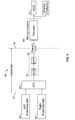
- Referring to
FIG. 1 , arotary baler 10 is towed by a powered vehicle 11 (e.g., a tractor) along acenterline 12 of aswath path 14 in whichcrop material 16 has been arranged into a pile, or awindrow 18. Baler 10 has abale forming chamber 34 that includes a pickup 36 withtines 37 configured to lift crop material from the ground and deliver it rearward tobaler chamber 34. A detailed description of anexemplary baler 10 is set forth inU.S. Patent No. 5,615,544 , incorporated by reference herein. - Powered
vehicle 11 is equipped with a global positioning system (GPS)sensor 20 and anautomatic guidance system 24.GPS sensor 20 receives location information from GPS which is representative ofvehicle 11 position in a field.Vehicle 11 is guided according to a map 26 that is stored inautomatic guidance system 24, typically created whilewindrow 18 was formed. Map 26 may include information representative of the location ofwindrow 18 in afield 22. For example, a centerline orA-B line 12 ofwindrow 18 may be approximately defined by a series ofline segments 13 defined by points 15 (Fig. 2 ) to form thecenterline 12. Map 26 may include information fromGPS sensor 20 which is representative ofbaler 10 location. Because it is not uncommon forwindrows 18 ofcrop material 16 to be narrower than the width of thebale forming chamber 34, it is necessary for the operator orautomatic guidance system 24 tosteer baler 10 along a path that results in substantially uniform transverse distribution of hay to avoid poorly shaped bales. Previously, this approach relied on the experience and technique of the operator to determine when to shift the position of the baler relative to the windrow. - Referring next to
FIG. 2 , in a first embodiment anautomatic guidance system 24 for abaler 10 is implemented in an open loop configuration.Automatic guidance system 24 references data provided by map 26 to determine anoscillatory path 30 alongA-B line 12.Oscillatory path 30 is predetermined based onA-B line 12. Recognizing that poweredvehicle 11 andbaler 10 will generally provide an unevenly distributed or shaped bale by simply following A-Bline 12,automatic guidance system 24 generates a set ofdata points 32 with reference toA-B line 12.Data points 32 connect to formoscillatory path 30.Automatic guidance system 24 steers poweredvehicle 11 from onedata point 32 to the nextadjacent data point 32, such thatpowered vehicle 11 crossesA-B line 12 in a periodic pattern that is generally symmetrical aboutA-B line 12.Automatic guidance system 24 may apply an algorithm that takes into account the difference in the width ofwindrow 18 andbaler 10 to calculate a characteristic frequency, or interval L versus time, and amplitude h, to steerpowered vehicle 11 andbaler 10 along a generally sinusoidaloscillatory path 30 with reference toA-B line 12, thus ensuring thatcrop material 16 is distributed evenly tobale forming chamber 34. - Automated steering systems are known in the art, for example, hydraulically actuated or electronically actuated steering wheels that adjust the direction of the wheels. While
Fig. 2 illustratedA-B line 12 as a straight line, it should be understood thatA-B line 12 may have an irregular or non-uniform contour, as the contour ofA-B line 12 may be dependent upon variations in elevation infield 22. Field may include hills and valleys and other naturally occurring contours, resulting in a line that is not straight. Even in alevel field 22,A-B line 12 may deviate from a straight line due to irregular boundary lines that may prevent or inhibit straight line trajectories. Thus,oscillatory path 30 may not appear to be sinusoidal due to undulations or perturbances in the profile ofA-B line 12. In one embodiment,baler chamber 34 may cover a width extending from afirst side 34a to an opposite,second side 34b, and amplitude h is equal to one-half of the width ofchamber 34, so that eachside windrow 18 equally in one interval L. Different algorithms may also be applied, which, e.g., account for angle of repose. - A
bale sensor assembly 45 is mounted on eitherside wall FIG. 1 . Although only two sensor assemblies are shown and described, it should be understood that the disclosed method contemplates the use of multiple, e.g., left and right sensors, and in some embodiments, more than two sensors, , e.g., a middle section sensor or sensors. In the two-sensor configuration, each sensor may be separately mounted on the inside of an associated opposing side wall ofbaler 10. A paired arrangement of this nature is disclosed inU.S. Pat. No. 5,444,969 , referred to above, which is hereby incorporated by reference. -
FIGS. 3 & 4 show asensor assembly 45 mounted onside wall FIG. 1 . Another sensor assembly is similarly mounted on the opposingside wall 34b ofbaler 10, in a paired arrangement as mentioned above. For the purposes of this description, only assembly 45 will be described in detail but it is intended that like comments would apply to its counterpart assembly mounted on opposingside wall 34b. - A mounting
bracket 47 affixed to the outside ofside wall potentiometer 48 and a pivotally mountedsensor plate 50. Aspring 51 engagesplate 50 to urge it in a counter-clockwise direction about abolt 52, at whichbolt plate 50 is pivotally mounted tobracket 47.Spring 51 under tension holdsplate 50 against the outside surface ofwall shoulder 49 in the empty chamber condition shown inFIG. 3 . Anintegral finger portion 53 ofplate 50 extends throughwall aperture 54.Finger 53 is urged toward aleaf spring 55 secured to the inside ofside wall Leaf spring 55 is preset in the position and shape shown inFIG. 3 under no load conditions.Spring 51 in such no load position provides force sufficient to maintainshoulder 49 in contact withwall finger portion 53 is in contact withleaf spring 55 but applies no force or a negligible force againstleaf spring 55. - A
slot 58 inplate 50 accommodates anactuator rod 60 extending from arocker arm 61. Whenplate 50 pivots aboutbolt 52,rod 60 traversesslot 58 and thereby movesrocker arm 61 between the position shown inFIG. 3 and the position shown inFIG. 4 , in which the position of the elements ofsensor assembly 45 is shown under conditions where maximum crop compaction in the vicinity ofsensor assembly 45 is sensed. -
Potentiometer 48 may be any commercially available potentiometer. Anexemplary potentiometer 48 is manufactured by CTS Corporation, of Elkhart, Ind.Potentiometer 48 may be a sealed unit which enhances system integrity in the dust and debris laden environment under whichrotary baler 10 typically operates.Potentiometer 48 is rotatable against a spring in a conventional manner.Potentiometer 48 is urged in a clockwise direction and thereby acts withspring 51 to urgerocker arm 61 in a counter-clockwise direction. The position of thepotentiometer 48 is precisely maintained relative torocker arm 61 and accordingly,leaf spring 55. - An exemplary electrical system diagram of
FIG. 5 comprises a signal input section to the left ofline 81, a controller section, betweenlines automatic guidance system 24 to the right ofline 82. The sensors of the input section are mounted on the baler as discussed above, as is the controller, whileautomatic guidance system 24 is remotely located, e.g., in the control area of the tractor to which the round baler is coupled. - More specifically,
potentiometers digital converter circuit 83, which produces digital values or signals representative of the analog inputs in a conventional manner. These digital values or signals are processed in amicroprocessor 84 which is programmed to evaluate the incoming values, based on signals sensed by the potentiometers, and yield digital data corresponding to averaged levels of comparative degrees of compaction. This data is transferred via aserial link 85 interconnecting the controller andautomatic guidance system 24 in data communication with asecond microprocessor 86 programmed for decoding the digital data and producing signals in a conventional manner for input toautomatic guidance system 24, and, optionally, for display in display unit 78. - The data that is derived from signals at
potentiometers automatic guidance system 24, viaserial link 85, with attendant advantages of such data transfer in an adverse environment, which include the presence of various magnetic and electrical components that generate unwanted transient noise that could lead to adverse effects on analog data. Another advantage of the serial link system is the ability for the round baler and incorporated controller to be readily disconnected and recoupled to any tractor equipped with a compatible operator panel. - Referring next to
Fig. 1A in operation, as mentioned above, crop material is picked up bypickup 23 and conveyed by tines tofloor roll 19 which urges it against upwardly traveling course c of apron 33. Initially, when the bale forming chamber is empty material begins to spiral in a clockwise direction until it engages the rollers ofsledge assembly 21 which continue to coil it in a spiral fashion causing course c to expand until it reaches the full bale position. During such bale forming operation, crop material adjacent the side walls in the peripheral portion of the cylindrical package being formed is in continuous contact withleaf spring 55 of opposing similar sensor assemblies 45 (FIGS. 3 and 4 ). More specifically, crop material traverses the leaf springs in a longitudinal fashion along a generally spiral path from the upstream end 79 to thedownstream end 82. In this manner the degree of crop compaction is sensed as the preset bias is overcome and the leaf springs are urged toward the side walls. The position ofpotentiometer - Thus, as the cylindrical package of crop material increases in size, the comparative degree of compactness of its ends is monitored, enabling the
automatic guidance system 24 to modify the relative quantity of crop material being fed to the transverse regions of the bale forming chamber in response to left andright potentiometer 45 output voltages. For example, when a predetermined differential of levels is exceeded and the left end is low, theautomatic guidance system 24 detects an imbalance in the voltage output of potentiometers. In this instance, theautomatic guidance system 24 will steer the baler to fill the left side or adjust the length of internal L, i.e., frequency of theoscillatory path 30 until the left and right levels of compaction reach an acceptable relationship. In the event the comparative degree of compaction displayed in the readout reaches an unacceptable relationship due to low compaction on the right end of the cylindrical package of crop material being formed in the chamber as compared to the left end, theautomatic guidance system 24 reacts by steeringvehicle 11 to fill the right side withcrop material 16 until thepotentiometer 48 output voltages become balanced or attain an acceptable proportionate relationship. - In one embodiment, analog signals provided by
potentiometers FIG. 5 ) and converted to digital values or signals that are processed to provide comparative signals. Signals may optionally be displayed to an operator by a display unit 78. The digital values are used to adjustoscillatory path 30 as computed byautomatic guidance system 24. If one ormore sensors 45 indicate an imbalance or asymmetric bale shape,automatic guidance system 24 may adjust the interval length L or the amplitude h ofoscillatory path 30 based on the feedback provided by the comparative signals. Once the sensors respective output signals cancel one another, or become balanced again,automatic guidance system 24 may return to steering poweredvehicle 11 along the originally computedoscillatory path 30, i.e., applying the original parameters for frequency and amplitude h foroscillatory path 30. In another embodiment,automatic guidance system 24 may substitute the adjusted oscillatory path 30' in place of the originaloscillatory path 30. - According to the disclosure,
automatic guidance system 24 integrates bale shape information frombale shape sensors 45 to adjust amplitude h and/or interval L ofoscillatory path 30, and transmits a corresponding steering command to a steering system ofpowered vehicle 11 to actuate steerable wheels ofpowered vehicle 11 along a desired path for evenly distributing crop material inrotary baler 10. - Now referring to
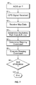
FIG. 6 , one embodiment of the method is disclosed. By reference to map 26, abaler swath path 14 may be implemented. Atstep 90 anautomatic guidance system 24 is verified as operational, and atblock 91 GPS coordinates information is received byautomatic guidance system 24. Next,system 24 proceeds to step 92 and obtains map data defining A-B lines 12. Atstep 93,system 24 determines anoscillatory path 30 based onA-B lines 12. Based on GPS information,A-B lines 12 andoscillatory paths 30, a steering command is determined byautomatic guidance system 24 atstep 94. Atstep 95, the steering command is executed by the steering system ofvehicle 11, to causevehicle 11 to follow a path in the field that approximately corresponds to or substantially coincides withoscillatory path 30. Atstep 96, asvehicle 11 traversesfield 22,automatic guidance system 24 monitors information frombale sensors 45 and proceeds todecision step 97. If atstep 97bale sensors 45 indicate an imbalance ofcrop material 16 that forms the bale inbale chamber 34,automatic guidance system 24 proceeds to step 98 whereautomatic guidance system 24 determines an adjustment tooscillatory path 30, i.e., interval L and/or amplitude h. Fromstep 98,automatic guidance system 24 returns to step 94 and resumes steering commands according to the recomputed oscillatory path. If atstep 98 there is no imbalance ofcrop material 16 indicated bybale chamber sensors 45, thenautomatic guidance system 24 proceeds to step 99, and resumes originaloscillatory path 30.Automatic guidance system 24 then returns to step 91. - In another embodiment,
automatic guidance system 24 may implement an open loop steering configuration, i.e., without sensor feedback frombale chamber sensors 45. Referring toFIG. 7 , atstep 90 anautomatic guidance system 24 is verified as operational, and atblock 91 GPS information is received byautomatic guidance system 24. Next,system 24 proceeds to step 92 and obtains map data defining A-B lines 12. Atstep 93,system 24 determines anoscillatory path 30 based onA-B line 12. Based on GPS information,A-B line 12 andoscillatory path 30, a steering command is determined byautomatic guidance system 24 atstep 94. Atstep 95, the steering command is executed by the steering system ofvehicle 11 and proceeds todecision step 89. If atstep 89,vehicle 11 has traversed the length ofwindrow 18, thenautomatic guidance system 24 is ended atstep 101. - While the invention has been described with reference to a preferred embodiment, it will be understood by those skilled in the art that various changes may be made and equivalents may be substituted for elements thereof without departing from the scope of the invention. In addition, many modifications may be made to adapt a particular situation or material to the teachings of the invention without departing from the essential scope thereof. Therefore, it is intended that the invention not be limited to the particular embodiment disclosed as the best mode contemplated for carrying out this invention, but that the invention will include all embodiments falling within the scope of the appended claims.
Claims (14)
- A method for automatically guiding a powered vehicle (11) towing an agricultural implement (10) for producing an even distribution of crop material in a bale, the method comprising:- generating and storing a map (26) of information representative of a location of a first path (12) in a field;- receiving a location information representative of a position of the powered vehicle (11) in the field;- retrieving map data (26) defining the first path (12);- determining a second path (30) that oscillates about the first path (12); and
characterized in that said method further comprises:- generating a steering command based on at least one of the location information, the first path (12), or the second path (30); and- executing the steering command by a steering system of the powered vehicle (11) to steer the powered vehicle (11) along a path that corresponds to the second path (30). - The method of claim 1, further comprising the steps of:- monitoring a bale shape information by the auto guidance system (24) from a plurality of bale sensors (45) disposed in the agricultural implement (10), each of the bale sensors (45) configured to generate an indicating signal representing the distribution of crop material in a bale chamber (34) of the agricultural implement (10); and- adjusting the second path (30) in response to a plurality of the indicating signals indicating an imbalance of crop material in the bale chamber (34).
- The method of claim 2, further comprising the steps of:- providing an automatic guidance system (24) configured for steering the powered vehicle (11); and- steering the powered vehicle (11) via the automatic guidance system (24).
- The method according to any of the preceding claims, wherein the second path (30) further comprises a generally sinusoidal path symmetrical about the first path (12) having a periodic interval.
- The method of claim 4, wherein the sinusoidal second path (30) is further characterized by an amplitude defining a maximum distance of the second path (30) from the first path (12).
- The method of claim 5, wherein the step of adjusting the second path (30) comprises adjusting at least one of the periodic interval and amplitude.
- The method of claim 6, wherein the automatic guidance system (24) resumes steering the powered vehicle (11) according to the adjusted second path (30').
- The method of claim 2 and any claim dependent thereon, further comprising the step of:in response to the plurality of bale chamber sensors (45) indicating that crop material in the bale chamber (34) is substantially balanced, then automatic guidance system (24) resumes original oscillatory second path (30).
- The method according to any of the preceding claims, further comprising:verifying that an automatic guidance system (24) is operational.
- The method according to any of the preceding claims, wherein the first path (12) represents an approximate centerline of a windrow (18) of crop material.
- A system for automatically guiding a powered vehicle (11) towing an agricultural implement (10) for producing an even distribution of a crop material in a bale, the system comprising:- a powered vehicle (11), a rotary baler (10), a global positioning system (20) and an automatic guidance system (24);- the powered vehicle (11) comprising a global positioning system (GPS) sensor and an automatic guidance system (24), the GPS sensor configured to receive information representative of a geographic location of the powered vehicle (11); and- the automatic guidance system (24) comprising a map (26) stored in a data memory;wherein the automatic guidance system (24) is configured to:- receive a location information representative of a position of the powered vehicle (11) in the field;- retrieve map data defining the first path (12);- determine a second path (30) that oscillates about the first path (12); and characterized in that said system further comprises:- generate a steering command based on at least one of the location information, the first path (12), or the second path (30); and- execute the steering command by a steering system of the powered vehicle (11) to steer the powered vehicle (11) along a path that corresponds to the second path (30).
- The system of claim 11, further comprising:the automatic guidance system (24) further configured to:- monitor a bale shape information by the auto guidance system from a plurality of bale sensors (45) disposed in the agricultural implement (10), each of the bale sensors (45) configured to generate an indicating signal representing the distribution of the crop material in a bale chamber (34) of the agricultural implement (10); and- adjust the second path (30) in response to a plurality of the indicating signals indicating an imbalance of the crop material in the bale chamber (34).
- The system of claim 12, further comprising:the rotary baler (10) comprising a plurality of bale chambers (34), one of the plurality of bale sensors (45) associated with each bale chamber (34); the rotary baler (10) being towed by the powered vehicle (11) along an approximate centerline in which the crop material has been arranged into a windrow (18).
- The system of claim 12 or 13, further comprising:- a plurality of potentiometers (48, 48'), an analog-to-digital converter circuit (83), a first microprocessor (84) associated with the controller (89), a serial link (85) interconnecting the controller (89) and the automatic guidance system (24); and a second microprocessor (86) associated with the automatic guidance system (24);- the potentiometers (48, 48') connected to produce analog signals into the analog-to-digital converter circuit (83); the analog-to-digital converter circuit (83) configured to produce digital signals representative of the analog signals; the microprocessor (84) programmed to process the digital signals and produce digital data representing averaged levels of comparative degrees of compaction of the crop material (16); the serial link (85) configured to transmit the digital data from the controller (89) to the second microprocessor (86); the second microprocessor (86) programmed to decode the digital data and transmit signals to the automatic guidance system (24).
Applications Claiming Priority (1)
| Application Number | Priority Date | Filing Date | Title |
|---|---|---|---|
| US12/483,400 US8234033B2 (en) | 2009-06-12 | 2009-06-12 | Guidance method for agricultural vehicle |
Publications (3)
| Publication Number | Publication Date |
|---|---|
| EP2267567A2 true EP2267567A2 (en) | 2010-12-29 |
| EP2267567A3 EP2267567A3 (en) | 2011-11-30 |
| EP2267567B1 EP2267567B1 (en) | 2014-08-13 |
Family
ID=42712449
Family Applications (1)
| Application Number | Title | Priority Date | Filing Date |
|---|---|---|---|
| EP10165566.0A Active EP2267567B1 (en) | 2009-06-12 | 2010-06-10 | Guidance method for agricultural vehicle |
Country Status (2)
| Country | Link |
|---|---|
| US (2) | US8234033B2 (en) |
| EP (1) | EP2267567B1 (en) |
Cited By (8)
| Publication number | Priority date | Publication date | Assignee | Title |
|---|---|---|---|---|
| WO2015077452A1 (en) * | 2013-11-20 | 2015-05-28 | Rowbot Systems Llc | Robotic platform and method for performing multiple functions in agricultural systems |
| US9265187B2 (en) | 2013-11-20 | 2016-02-23 | Rowbot Systems Llc | Robotic platform and method for performing multiple functions in agricultural systems |
| US9288938B2 (en) | 2012-06-01 | 2016-03-22 | Rowbot Systems Llc | Robotic platform and method for performing multiple functions in agricultural systems |
| US9392743B2 (en) | 2013-08-14 | 2016-07-19 | Rowbot Systems Llc | Agricultural autonomous vehicle platform with articulated base |
| EP3189722A1 (en) * | 2016-01-11 | 2017-07-12 | PÖTTINGER Landtechnik GmbH | Automated steering in round balers |
| EP3398420A1 (en) | 2017-05-02 | 2018-11-07 | Deere & Company | Method and assembly for controlling the speed a baler |
| EP3756448A1 (en) * | 2019-06-25 | 2020-12-30 | Deere & Company | Round baler crop distribution system |
| EP3841868A1 (en) * | 2019-12-27 | 2021-06-30 | AGCO International GmbH | System and method for windrow path planning |
Families Citing this family (22)
| Publication number | Priority date | Publication date | Assignee | Title |
|---|---|---|---|---|
| DE102009047585A1 (en) * | 2009-12-07 | 2011-06-09 | Deere & Company, Moline | Combination of a towing vehicle and a device |
| US8694382B2 (en) * | 2011-02-18 | 2014-04-08 | Cnh America Llc | System and method for automatic guidance control of a vehicle |
| US9078398B2 (en) * | 2012-05-25 | 2015-07-14 | Deere & Company | Agricultural baler with shape sensors and method |
| US20140083071A1 (en) * | 2012-09-25 | 2014-03-27 | Ii Jeffrey Fay | Active steering windrow shields |
| WO2014052712A2 (en) * | 2012-09-28 | 2014-04-03 | Agco Corporation | Windrow relative yield determination through stereo imaging |
| US8935979B2 (en) | 2012-12-14 | 2015-01-20 | Cnh Industrial America Llc | Even bale block for monitoring bale shape in a round baler |
| US9791863B2 (en) * | 2013-11-11 | 2017-10-17 | Deere & Company | Location-based material gathering |
| US9706697B2 (en) * | 2015-07-29 | 2017-07-18 | Claas Omaha, Inc. | Agricultural system with a baler and tow tractor and a steering arrangement by which the baler is steered autonomously |
| US9795074B2 (en) | 2015-10-27 | 2017-10-24 | Cnh Industrial America Llc | Automatic swath generation device and methods |
| US9750173B2 (en) | 2015-10-27 | 2017-09-05 | Cnh Industrial America Llc | Device and method for guiding agricultural vehicles using modified swath width |
| US9930834B2 (en) | 2015-10-29 | 2018-04-03 | Deere & Company | Agricultural baler control system |
| US9826673B1 (en) * | 2016-05-27 | 2017-11-28 | Cnh Industrial America Llc | Swath acquisition system for an agricultural vehicle |
| DE102016221104A1 (en) * | 2016-10-26 | 2018-04-26 | Deere & Company | Round baler, combination of an agricultural vehicle with such and method for pressing round bales |
| US10289696B2 (en) | 2016-10-31 | 2019-05-14 | Deere & Company | Yield mapping for an agricultural harvesting machine |
| BE1024459B1 (en) * | 2017-05-09 | 2018-02-26 | Cnh Industrial Belgium Nv | AGRICULTURAL SYSTEM |
| BE1024473B1 (en) * | 2017-05-09 | 2018-02-28 | Cnh Ind Belgium Nv | AGRICULTURAL SYSTEM |
| BE1024928B1 (en) * | 2017-05-09 | 2018-08-13 | Cnh Industrial Belgium Nv | IMPROVEMENTS IN OR RELATING TO TRACTOR / BALER PRESS COMBINATIONS |
| US11684015B2 (en) | 2019-08-07 | 2023-06-27 | Cnh Industrial America Llc | Agricultural baling system with controlled tractor steering to balance bale density |
| US20210246636A1 (en) * | 2020-02-07 | 2021-08-12 | Caterpillar Inc. | System and Method of Autonomously Clearing a Windrow |
| US11337356B2 (en) * | 2020-03-12 | 2022-05-24 | Deere & Company | Crop orientation system and method |
| US20220225557A1 (en) * | 2021-01-18 | 2022-07-21 | Cnh Industrial America Llc | Bale retriever that generates driveable path for efficiency and to reduce compaction |
| US20230142286A1 (en) * | 2021-11-10 | 2023-05-11 | Deere & Company | Combine harvester operation based on windrow data stream |
Citations (2)
| Publication number | Priority date | Publication date | Assignee | Title |
|---|---|---|---|---|
| US5444969A (en) | 1993-07-12 | 1995-08-29 | New Holland North America, Inc. | Round baler apparatus for monitoring bale shape |
| US5615544A (en) | 1996-02-13 | 1997-04-01 | New Holland North America, Inc. | System for monitoring the shape of round bales |
Family Cites Families (27)
| Publication number | Priority date | Publication date | Assignee | Title |
|---|---|---|---|---|
| US4065914A (en) | 1976-03-15 | 1978-01-03 | International Harvester Company | Offset baler with steerable control |
| US4224867A (en) | 1979-03-21 | 1980-09-30 | Hesston Corporation | Crop loading monitor for rotary balers |
| DE2912715C2 (en) | 1979-03-30 | 1983-08-04 | Klöckner-Humboldt-Deutz AG Zweigniederlassung Fahr, 7702 Gottmadingen | Pulled harvester |
| DE3166404D1 (en) | 1981-03-25 | 1984-11-08 | Deere John | Baling press |
| US4702066A (en) * | 1986-07-25 | 1987-10-27 | Vermeer Manufacturing Company | Round baler with automatic steering system |
| US4748801A (en) | 1987-04-13 | 1988-06-07 | New Holland Inc. | System for automatically controlling bale shape in round balers |
| US4924405A (en) | 1987-05-14 | 1990-05-08 | Ford New Holland, Inc. | Round baler with continuous bale size monitoring |
| US5152123A (en) | 1989-12-27 | 1992-10-06 | Deere & Company | Indicator system for alerting an operator to the condition of a large cylindrical bale wrapping mechanism |
| US5131214A (en) | 1991-01-15 | 1992-07-21 | Vermeer Manufacturing Company | Baler fill monitor |
| US5226359A (en) | 1992-03-10 | 1993-07-13 | Vermeer Manufacturing Company | Bale size indicator |
| US5551218A (en) | 1994-09-19 | 1996-09-03 | Gehl Company | Round baler monitoring and control system |
| USH1819H (en) | 1998-03-25 | 1999-12-07 | Hay & Forage Industries | Bale shape monitor for round balers |
| US6622455B2 (en) | 2000-09-12 | 2003-09-23 | Agco Corporation | Round baler with semi-automatically sequenced operating cycles and selectively variable point of operator intervention |
| US6539303B2 (en) | 2000-12-08 | 2003-03-25 | Mcclure John A. | GPS derived swathing guidance system |
| US6874412B1 (en) | 2001-08-10 | 2005-04-05 | Gehl Company | Bale shape monitoring system for a round baler |
| US7142956B2 (en) | 2004-03-19 | 2006-11-28 | Hemisphere Gps Llc | Automatic steering system and method |
| US7216033B2 (en) | 2003-03-31 | 2007-05-08 | Deere & Company | Path planner and method for planning a contour path of a vehicle |
| US20040199303A1 (en) * | 2003-04-01 | 2004-10-07 | Nikon Corporation | Rental vehicle system, in-vehicle computer system, digital camera system and digital camera |
| DE102004022801A1 (en) | 2004-05-08 | 2005-12-15 | Deere & Company, Moline | Round baler |
| DE102004042740A1 (en) | 2004-09-03 | 2006-03-23 | Deere & Company, Moline | Round baler with a bale forming chamber of variable size and a device for measuring the diameter and shape of a round bale |
| US7451030B2 (en) | 2005-02-04 | 2008-11-11 | Novariant, Inc. | System and method for interactive selection and determination of agricultural vehicle guide paths offset from each other with varying curvature along their length |
| RU2365087C1 (en) * | 2005-09-14 | 2009-08-27 | АГРОКОМ Фервальтунгс ГмбХ | Control method of pick up baler and pick up baler |
| US7363154B2 (en) | 2005-10-12 | 2008-04-22 | Trimble Navigation Limited | Method and system for determining the path of a mobile machine |
| US7404355B2 (en) * | 2006-01-31 | 2008-07-29 | Deere & Company | Tractor and baler combination with automatic baling and tractor halt control |
| US7913482B2 (en) | 2006-10-11 | 2011-03-29 | Acco Corporation | Bale shape monitor for round balers |
| US8010261B2 (en) | 2007-05-23 | 2011-08-30 | Cnh America Llc | Automatic steering correction of an agricultural harvester using integration of harvester header row sensors and harvester auto guidance system |
| DE602007013749D1 (en) * | 2007-08-22 | 2011-05-19 | Deere & Co | Bales with automatic sensor calibration |
-
2009
- 2009-06-12 US US12/483,400 patent/US8234033B2/en active Active
-
2010
- 2010-06-10 EP EP10165566.0A patent/EP2267567B1/en active Active
-
2012
- 2012-06-21 US US13/529,891 patent/US8571744B2/en active Active
Patent Citations (2)
| Publication number | Priority date | Publication date | Assignee | Title |
|---|---|---|---|---|
| US5444969A (en) | 1993-07-12 | 1995-08-29 | New Holland North America, Inc. | Round baler apparatus for monitoring bale shape |
| US5615544A (en) | 1996-02-13 | 1997-04-01 | New Holland North America, Inc. | System for monitoring the shape of round bales |
Cited By (14)
| Publication number | Priority date | Publication date | Assignee | Title |
|---|---|---|---|---|
| US9288938B2 (en) | 2012-06-01 | 2016-03-22 | Rowbot Systems Llc | Robotic platform and method for performing multiple functions in agricultural systems |
| US10123473B2 (en) | 2012-06-01 | 2018-11-13 | Rowbot Systems Llc | Robotic platform and method for performing multiple functions in agricultural systems |
| US9392743B2 (en) | 2013-08-14 | 2016-07-19 | Rowbot Systems Llc | Agricultural autonomous vehicle platform with articulated base |
| WO2015077452A1 (en) * | 2013-11-20 | 2015-05-28 | Rowbot Systems Llc | Robotic platform and method for performing multiple functions in agricultural systems |
| US9265187B2 (en) | 2013-11-20 | 2016-02-23 | Rowbot Systems Llc | Robotic platform and method for performing multiple functions in agricultural systems |
| US10528048B2 (en) | 2013-11-20 | 2020-01-07 | Rowbot Systems Llc | Robotic platform and method for performing multiple functions in agricultural systems |
| US10890912B2 (en) | 2013-11-20 | 2021-01-12 | Rowbot Systems Llc | Robotic platform and method for performing multiple functions in agricultural systems |
| EP3189722A1 (en) * | 2016-01-11 | 2017-07-12 | PÖTTINGER Landtechnik GmbH | Automated steering in round balers |
| EP3189722B1 (en) | 2016-01-11 | 2019-03-27 | PÖTTINGER Landtechnik GmbH | Automated steering in round balers |
| EP3398420A1 (en) | 2017-05-02 | 2018-11-07 | Deere & Company | Method and assembly for controlling the speed a baler |
| US10694670B2 (en) | 2017-05-02 | 2020-06-30 | Deere & Company | Method and arrangement for control of the speed of a baler |
| EP3756448A1 (en) * | 2019-06-25 | 2020-12-30 | Deere & Company | Round baler crop distribution system |
| US11399468B2 (en) | 2019-06-25 | 2022-08-02 | Deere & Company | Round baler crop distribution system |
| EP3841868A1 (en) * | 2019-12-27 | 2021-06-30 | AGCO International GmbH | System and method for windrow path planning |
Also Published As
| Publication number | Publication date |
|---|---|
| EP2267567B1 (en) | 2014-08-13 |
| EP2267567A3 (en) | 2011-11-30 |
| US20100318253A1 (en) | 2010-12-16 |
| US8571744B2 (en) | 2013-10-29 |
| US8234033B2 (en) | 2012-07-31 |
| US20120265392A1 (en) | 2012-10-18 |
Similar Documents
| Publication | Publication Date | Title |
|---|---|---|
| EP2267567B1 (en) | Guidance method for agricultural vehicle | |
| US10925205B2 (en) | Tractor-trailer combinations | |
| US9849909B2 (en) | Towable agricultural implement having automatic steering system | |
| US6236916B1 (en) | Autoguidance system and method for an agricultural machine | |
| US8494726B2 (en) | Agricultural autopilot path adjustment | |
| US20120240546A1 (en) | Tractor Implement Combination | |
| US20110125371A1 (en) | Auto-Steerable Farming System | |
| US8359141B1 (en) | Calibrated farming system | |
| US20160324066A1 (en) | Active steering windrow shields | |
| EP2870857B1 (en) | A computer-implemented control system for gathering material and method for such | |
| US11812680B2 (en) | Tractor-baler combinations | |
| US20060064216A1 (en) | Automatic steering system | |
| US9901021B2 (en) | Tactile guidance arrangement for vehicles | |
| US11730078B2 (en) | Work vehicle with row unit having variable steering angle | |
| AU6134800A (en) | Apparatus and method for controlling the position of an arm on a hitch | |
| US11684015B2 (en) | Agricultural baling system with controlled tractor steering to balance bale density | |
| NZ759247B2 (en) | Improvements in or relating to tractor-baler combinations |
Legal Events
| Date | Code | Title | Description |
|---|---|---|---|
| PUAI | Public reference made under article 153(3) epc to a published international application that has entered the european phase |
Free format text: ORIGINAL CODE: 0009012 |
|
| AK | Designated contracting states |
Kind code of ref document: A2 Designated state(s): AL AT BE BG CH CY CZ DE DK EE ES FI FR GB GR HR HU IE IS IT LI LT LU LV MC MK MT NL NO PL PT RO SE SI SK SM TR |
|
| AX | Request for extension of the european patent |
Extension state: BA ME RS |
|
| RAP1 | Party data changed (applicant data changed or rights of an application transferred) |
Owner name: CNH ITALIA S.P.A. |
|
| PUAL | Search report despatched |
Free format text: ORIGINAL CODE: 0009013 |
|
| RIC1 | Information provided on ipc code assigned before grant |
Ipc: A01F 15/08 20060101AFI20110926BHEP Ipc: A01B 69/00 20060101ALI20110926BHEP Ipc: G05D 1/02 20060101ALI20110926BHEP |
|
| AK | Designated contracting states |
Kind code of ref document: A3 Designated state(s): AL AT BE BG CH CY CZ DE DK EE ES FI FR GB GR HR HU IE IS IT LI LT LU LV MC MK MT NL NO PL PT RO SE SI SK SM TR |
|
| AX | Request for extension of the european patent |
Extension state: BA ME RS |
|
| 17P | Request for examination filed |
Effective date: 20120530 |
|
| 17Q | First examination report despatched |
Effective date: 20120903 |
|
| REG | Reference to a national code |
Ref country code: DE Ref legal event code: R079 Ref document number: 602010018156 Country of ref document: DE Free format text: PREVIOUS MAIN CLASS: G05D0001020000 Ipc: A01F0015080000 |
|
| RIC1 | Information provided on ipc code assigned before grant |
Ipc: A01F 15/08 20060101AFI20140211BHEP Ipc: G05D 1/02 20060101ALI20140211BHEP Ipc: A01B 69/04 20060101ALI20140211BHEP |
|
| GRAP | Despatch of communication of intention to grant a patent |
Free format text: ORIGINAL CODE: EPIDOSNIGR1 |
|
| INTG | Intention to grant announced |
Effective date: 20140325 |
|
| RAP1 | Party data changed (applicant data changed or rights of an application transferred) |
Owner name: CNH INDUSTRIAL ITALIA S.P.A. |
|
| GRAS | Grant fee paid |
Free format text: ORIGINAL CODE: EPIDOSNIGR3 |
|
| GRAA | (expected) grant |
Free format text: ORIGINAL CODE: 0009210 |
|
| AK | Designated contracting states |
Kind code of ref document: B1 Designated state(s): AL AT BE BG CH CY CZ DE DK EE ES FI FR GB GR HR HU IE IS IT LI LT LU LV MC MK MT NL NO PL PT RO SE SI SK SM TR |
|
| REG | Reference to a national code |
Ref country code: GB Ref legal event code: FG4D |
|
| REG | Reference to a national code |
Ref country code: CH Ref legal event code: EP Ref country code: AT Ref legal event code: REF Ref document number: 681562 Country of ref document: AT Kind code of ref document: T Effective date: 20140815 |
|
| REG | Reference to a national code |
Ref country code: IE Ref legal event code: FG4D |
|
| REG | Reference to a national code |
Ref country code: DE Ref legal event code: R096 Ref document number: 602010018156 Country of ref document: DE Effective date: 20140925 |
|
| REG | Reference to a national code |
Ref country code: NL Ref legal event code: VDEP Effective date: 20140813 |
|
| REG | Reference to a national code |
Ref country code: AT Ref legal event code: MK05 Ref document number: 681562 Country of ref document: AT Kind code of ref document: T Effective date: 20140813 |
|
| REG | Reference to a national code |
Ref country code: LT Ref legal event code: MG4D |
|
| PG25 | Lapsed in a contracting state [announced via postgrant information from national office to epo] |
Ref country code: NO Free format text: LAPSE BECAUSE OF FAILURE TO SUBMIT A TRANSLATION OF THE DESCRIPTION OR TO PAY THE FEE WITHIN THE PRESCRIBED TIME-LIMIT Effective date: 20141113 Ref country code: BG Free format text: LAPSE BECAUSE OF FAILURE TO SUBMIT A TRANSLATION OF THE DESCRIPTION OR TO PAY THE FEE WITHIN THE PRESCRIBED TIME-LIMIT Effective date: 20141113 Ref country code: GR Free format text: LAPSE BECAUSE OF FAILURE TO SUBMIT A TRANSLATION OF THE DESCRIPTION OR TO PAY THE FEE WITHIN THE PRESCRIBED TIME-LIMIT Effective date: 20141114 Ref country code: PT Free format text: LAPSE BECAUSE OF FAILURE TO SUBMIT A TRANSLATION OF THE DESCRIPTION OR TO PAY THE FEE WITHIN THE PRESCRIBED TIME-LIMIT Effective date: 20141215 Ref country code: SE Free format text: LAPSE BECAUSE OF FAILURE TO SUBMIT A TRANSLATION OF THE DESCRIPTION OR TO PAY THE FEE WITHIN THE PRESCRIBED TIME-LIMIT Effective date: 20140813 Ref country code: FI Free format text: LAPSE BECAUSE OF FAILURE TO SUBMIT A TRANSLATION OF THE DESCRIPTION OR TO PAY THE FEE WITHIN THE PRESCRIBED TIME-LIMIT Effective date: 20140813 Ref country code: LT Free format text: LAPSE BECAUSE OF FAILURE TO SUBMIT A TRANSLATION OF THE DESCRIPTION OR TO PAY THE FEE WITHIN THE PRESCRIBED TIME-LIMIT Effective date: 20140813 Ref country code: ES Free format text: LAPSE BECAUSE OF FAILURE TO SUBMIT A TRANSLATION OF THE DESCRIPTION OR TO PAY THE FEE WITHIN THE PRESCRIBED TIME-LIMIT Effective date: 20140813 |
|
| PG25 | Lapsed in a contracting state [announced via postgrant information from national office to epo] |
Ref country code: CY Free format text: LAPSE BECAUSE OF FAILURE TO SUBMIT A TRANSLATION OF THE DESCRIPTION OR TO PAY THE FEE WITHIN THE PRESCRIBED TIME-LIMIT Effective date: 20140813 Ref country code: LV Free format text: LAPSE BECAUSE OF FAILURE TO SUBMIT A TRANSLATION OF THE DESCRIPTION OR TO PAY THE FEE WITHIN THE PRESCRIBED TIME-LIMIT Effective date: 20140813 Ref country code: HR Free format text: LAPSE BECAUSE OF FAILURE TO SUBMIT A TRANSLATION OF THE DESCRIPTION OR TO PAY THE FEE WITHIN THE PRESCRIBED TIME-LIMIT Effective date: 20140813 Ref country code: AT Free format text: LAPSE BECAUSE OF FAILURE TO SUBMIT A TRANSLATION OF THE DESCRIPTION OR TO PAY THE FEE WITHIN THE PRESCRIBED TIME-LIMIT Effective date: 20140813 Ref country code: IS Free format text: LAPSE BECAUSE OF FAILURE TO SUBMIT A TRANSLATION OF THE DESCRIPTION OR TO PAY THE FEE WITHIN THE PRESCRIBED TIME-LIMIT Effective date: 20141213 |
|
| PG25 | Lapsed in a contracting state [announced via postgrant information from national office to epo] |
Ref country code: NL Free format text: LAPSE BECAUSE OF FAILURE TO SUBMIT A TRANSLATION OF THE DESCRIPTION OR TO PAY THE FEE WITHIN THE PRESCRIBED TIME-LIMIT Effective date: 20140813 |
|
| PG25 | Lapsed in a contracting state [announced via postgrant information from national office to epo] |
Ref country code: RO Free format text: LAPSE BECAUSE OF FAILURE TO SUBMIT A TRANSLATION OF THE DESCRIPTION OR TO PAY THE FEE WITHIN THE PRESCRIBED TIME-LIMIT Effective date: 20140813 Ref country code: EE Free format text: LAPSE BECAUSE OF FAILURE TO SUBMIT A TRANSLATION OF THE DESCRIPTION OR TO PAY THE FEE WITHIN THE PRESCRIBED TIME-LIMIT Effective date: 20140813 Ref country code: SK Free format text: LAPSE BECAUSE OF FAILURE TO SUBMIT A TRANSLATION OF THE DESCRIPTION OR TO PAY THE FEE WITHIN THE PRESCRIBED TIME-LIMIT Effective date: 20140813 Ref country code: CZ Free format text: LAPSE BECAUSE OF FAILURE TO SUBMIT A TRANSLATION OF THE DESCRIPTION OR TO PAY THE FEE WITHIN THE PRESCRIBED TIME-LIMIT Effective date: 20140813 Ref country code: DK Free format text: LAPSE BECAUSE OF FAILURE TO SUBMIT A TRANSLATION OF THE DESCRIPTION OR TO PAY THE FEE WITHIN THE PRESCRIBED TIME-LIMIT Effective date: 20140813 |
|
| REG | Reference to a national code |
Ref country code: DE Ref legal event code: R097 Ref document number: 602010018156 Country of ref document: DE |
|
| PG25 | Lapsed in a contracting state [announced via postgrant information from national office to epo] |
Ref country code: PL Free format text: LAPSE BECAUSE OF FAILURE TO SUBMIT A TRANSLATION OF THE DESCRIPTION OR TO PAY THE FEE WITHIN THE PRESCRIBED TIME-LIMIT Effective date: 20140813 |
|
| PLBE | No opposition filed within time limit |
Free format text: ORIGINAL CODE: 0009261 |
|
| STAA | Information on the status of an ep patent application or granted ep patent |
Free format text: STATUS: NO OPPOSITION FILED WITHIN TIME LIMIT |
|
| 26N | No opposition filed |
Effective date: 20150515 |
|
| PG25 | Lapsed in a contracting state [announced via postgrant information from national office to epo] |
Ref country code: SI Free format text: LAPSE BECAUSE OF FAILURE TO SUBMIT A TRANSLATION OF THE DESCRIPTION OR TO PAY THE FEE WITHIN THE PRESCRIBED TIME-LIMIT Effective date: 20140813 |
|
| PG25 | Lapsed in a contracting state [announced via postgrant information from national office to epo] |
Ref country code: MC Free format text: LAPSE BECAUSE OF FAILURE TO SUBMIT A TRANSLATION OF THE DESCRIPTION OR TO PAY THE FEE WITHIN THE PRESCRIBED TIME-LIMIT Effective date: 20140813 |
|
| REG | Reference to a national code |
Ref country code: CH Ref legal event code: PL |
|
| PG25 | Lapsed in a contracting state [announced via postgrant information from national office to epo] |
Ref country code: LU Free format text: LAPSE BECAUSE OF FAILURE TO SUBMIT A TRANSLATION OF THE DESCRIPTION OR TO PAY THE FEE WITHIN THE PRESCRIBED TIME-LIMIT Effective date: 20150610 |
|
| REG | Reference to a national code |
Ref country code: FR Ref legal event code: PLFP Year of fee payment: 7 Ref country code: IE Ref legal event code: MM4A |
|
| PG25 | Lapsed in a contracting state [announced via postgrant information from national office to epo] |
Ref country code: IE Free format text: LAPSE BECAUSE OF NON-PAYMENT OF DUE FEES Effective date: 20150610 Ref country code: LI Free format text: LAPSE BECAUSE OF NON-PAYMENT OF DUE FEES Effective date: 20150630 Ref country code: CH Free format text: LAPSE BECAUSE OF NON-PAYMENT OF DUE FEES Effective date: 20150630 |
|
| PG25 | Lapsed in a contracting state [announced via postgrant information from national office to epo] |
Ref country code: MT Free format text: LAPSE BECAUSE OF FAILURE TO SUBMIT A TRANSLATION OF THE DESCRIPTION OR TO PAY THE FEE WITHIN THE PRESCRIBED TIME-LIMIT Effective date: 20140813 |
|
| REG | Reference to a national code |
Ref country code: FR Ref legal event code: PLFP Year of fee payment: 8 |
|
| PG25 | Lapsed in a contracting state [announced via postgrant information from national office to epo] |
Ref country code: HU Free format text: LAPSE BECAUSE OF FAILURE TO SUBMIT A TRANSLATION OF THE DESCRIPTION OR TO PAY THE FEE WITHIN THE PRESCRIBED TIME-LIMIT; INVALID AB INITIO Effective date: 20100610 Ref country code: SM Free format text: LAPSE BECAUSE OF FAILURE TO SUBMIT A TRANSLATION OF THE DESCRIPTION OR TO PAY THE FEE WITHIN THE PRESCRIBED TIME-LIMIT Effective date: 20140813 |
|
| PG25 | Lapsed in a contracting state [announced via postgrant information from national office to epo] |
Ref country code: TR Free format text: LAPSE BECAUSE OF FAILURE TO SUBMIT A TRANSLATION OF THE DESCRIPTION OR TO PAY THE FEE WITHIN THE PRESCRIBED TIME-LIMIT Effective date: 20140813 |
|
| REG | Reference to a national code |
Ref country code: FR Ref legal event code: PLFP Year of fee payment: 9 |
|
| PG25 | Lapsed in a contracting state [announced via postgrant information from national office to epo] |
Ref country code: MK Free format text: LAPSE BECAUSE OF FAILURE TO SUBMIT A TRANSLATION OF THE DESCRIPTION OR TO PAY THE FEE WITHIN THE PRESCRIBED TIME-LIMIT Effective date: 20140813 |
|
| PG25 | Lapsed in a contracting state [announced via postgrant information from national office to epo] |
Ref country code: AL Free format text: LAPSE BECAUSE OF FAILURE TO SUBMIT A TRANSLATION OF THE DESCRIPTION OR TO PAY THE FEE WITHIN THE PRESCRIBED TIME-LIMIT Effective date: 20140813 |
|
| REG | Reference to a national code |
Ref country code: DE Ref legal event code: R082 Ref document number: 602010018156 Country of ref document: DE Representative=s name: MEISSNER BOLTE PATENTANWAELTE RECHTSANWAELTE P, DE |
|
| PGFP | Annual fee paid to national office [announced via postgrant information from national office to epo] |
Ref country code: IT Payment date: 20230612 Year of fee payment: 14 Ref country code: FR Payment date: 20230623 Year of fee payment: 14 Ref country code: DE Payment date: 20230627 Year of fee payment: 14 |
|
| PGFP | Annual fee paid to national office [announced via postgrant information from national office to epo] |
Ref country code: BE Payment date: 20230630 Year of fee payment: 14 |
|
| PGFP | Annual fee paid to national office [announced via postgrant information from national office to epo] |
Ref country code: GB Payment date: 20230622 Year of fee payment: 14 |