EP3123775B1 - Delaying a trigger of a scheduling request after handover - Google Patents
Delaying a trigger of a scheduling request after handover Download PDFInfo
- Publication number
- EP3123775B1 EP3123775B1 EP15717287.5A EP15717287A EP3123775B1 EP 3123775 B1 EP3123775 B1 EP 3123775B1 EP 15717287 A EP15717287 A EP 15717287A EP 3123775 B1 EP3123775 B1 EP 3123775B1
- Authority
- EP
- European Patent Office
- Prior art keywords
- base station
- mib
- handover
- time period
- predetermined time
- Prior art date
- Legal status (The legal status is an assumption and is not a legal conclusion. Google has not performed a legal analysis and makes no representation as to the accuracy of the status listed.)
- Active
Links
- 238000000034 method Methods 0.000 claims description 77
- 238000004891 communication Methods 0.000 claims description 73
- 230000005540 biological transmission Effects 0.000 claims description 38
- 230000000977 initiatory effect Effects 0.000 claims description 8
- 238000009795 derivation Methods 0.000 claims description 7
- 230000007774 longterm Effects 0.000 claims description 4
- 230000006870 function Effects 0.000 description 19
- 238000005516 engineering process Methods 0.000 description 11
- 238000010586 diagram Methods 0.000 description 8
- 230000008569 process Effects 0.000 description 8
- 238000004590 computer program Methods 0.000 description 7
- 230000001960 triggered effect Effects 0.000 description 5
- 238000012544 monitoring process Methods 0.000 description 4
- 238000012545 processing Methods 0.000 description 4
- 230000001360 synchronised effect Effects 0.000 description 4
- 230000003111 delayed effect Effects 0.000 description 3
- 230000003287 optical effect Effects 0.000 description 3
- 239000000969 carrier Substances 0.000 description 2
- 230000008859 change Effects 0.000 description 2
- 238000012790 confirmation Methods 0.000 description 2
- 239000000835 fiber Substances 0.000 description 2
- 238000012986 modification Methods 0.000 description 2
- 230000004048 modification Effects 0.000 description 2
- 230000008520 organization Effects 0.000 description 2
- 239000002245 particle Substances 0.000 description 2
- 230000004044 response Effects 0.000 description 2
- 230000001629 suppression Effects 0.000 description 2
- 238000012546 transfer Methods 0.000 description 2
- 238000003491 array Methods 0.000 description 1
- 230000001413 cellular effect Effects 0.000 description 1
- 239000003795 chemical substances by application Substances 0.000 description 1
- 230000001419 dependent effect Effects 0.000 description 1
- 238000001514 detection method Methods 0.000 description 1
- 238000005259 measurement Methods 0.000 description 1
- 238000010295 mobile communication Methods 0.000 description 1
- 230000000737 periodic effect Effects 0.000 description 1
- 230000002441 reversible effect Effects 0.000 description 1
- 230000011664 signaling Effects 0.000 description 1
- 230000007704 transition Effects 0.000 description 1
- 238000011144 upstream manufacturing Methods 0.000 description 1
Images


Classifications
-
- H—ELECTRICITY
- H04—ELECTRIC COMMUNICATION TECHNIQUE
- H04W—WIRELESS COMMUNICATION NETWORKS
- H04W36/00—Hand-off or reselection arrangements
- H04W36/0005—Control or signalling for completing the hand-off
- H04W36/0055—Transmission or use of information for re-establishing the radio link
- H04W36/0079—Transmission or use of information for re-establishing the radio link in case of hand-off failure or rejection
-
- H—ELECTRICITY
- H04—ELECTRIC COMMUNICATION TECHNIQUE
- H04W—WIRELESS COMMUNICATION NETWORKS
- H04W36/00—Hand-off or reselection arrangements
- H04W36/0005—Control or signalling for completing the hand-off
- H04W36/0011—Control or signalling for completing the hand-off for data sessions of end-to-end connection
-
- H—ELECTRICITY
- H04—ELECTRIC COMMUNICATION TECHNIQUE
- H04W—WIRELESS COMMUNICATION NETWORKS
- H04W36/00—Hand-off or reselection arrangements
- H04W36/08—Reselecting an access point
-
- H—ELECTRICITY
- H04—ELECTRIC COMMUNICATION TECHNIQUE
- H04W—WIRELESS COMMUNICATION NETWORKS
- H04W48/00—Access restriction; Network selection; Access point selection
- H04W48/16—Discovering, processing access restriction or access information
-
- H—ELECTRICITY
- H04—ELECTRIC COMMUNICATION TECHNIQUE
- H04W—WIRELESS COMMUNICATION NETWORKS
- H04W74/00—Wireless channel access
- H04W74/08—Non-scheduled access, e.g. ALOHA
- H04W74/0808—Non-scheduled access, e.g. ALOHA using carrier sensing, e.g. carrier sense multiple access [CSMA]
-
- H—ELECTRICITY
- H04—ELECTRIC COMMUNICATION TECHNIQUE
- H04W—WIRELESS COMMUNICATION NETWORKS
- H04W76/00—Connection management
- H04W76/10—Connection setup
- H04W76/18—Management of setup rejection or failure
-
- H—ELECTRICITY
- H04—ELECTRIC COMMUNICATION TECHNIQUE
- H04W—WIRELESS COMMUNICATION NETWORKS
- H04W36/00—Hand-off or reselection arrangements
- H04W36/0005—Control or signalling for completing the hand-off
- H04W36/0055—Transmission or use of information for re-establishing the radio link
- H04W36/0064—Transmission or use of information for re-establishing the radio link of control information between different access points
-
- H—ELECTRICITY
- H04—ELECTRIC COMMUNICATION TECHNIQUE
- H04W—WIRELESS COMMUNICATION NETWORKS
- H04W72/00—Local resource management
- H04W72/20—Control channels or signalling for resource management
- H04W72/21—Control channels or signalling for resource management in the uplink direction of a wireless link, i.e. towards the network
Definitions
- Wireless communications systems are widely deployed to provide various types of communication content such as voice, video, packet data, messaging, broadcast, and so on. These systems may be multiple-access systems capable of supporting communication with multiple users by sharing the available system resources (e.g., time, frequency, and power). Examples of such multiple-access systems include code-division multiple access (CDMA) systems, time-division multiple access (TDMA) systems, frequency-division multiple access (FDMA) systems, and orthogonal frequency-division multiple access (OFDMA) systems.
- CDMA code-division multiple access
- TDMA time-division multiple access
- FDMA frequency-division multiple access
- OFDMA orthogonal frequency-division multiple access
- a wireless multiple-access communications system may include a number of base stations, each simultaneously supporting communication for multiple mobile devices.
- Base stations may communicate with mobile devices on downstream and upstream links.
- Each base station has a coverage range, which may be referred to as the coverage area of the cell.
- a handoff occurs, in which communications with the mobile device are handed off from one base station in an initial coverage area to another base station in another coverage area.
- a handoff procedure often includes exchanging information between the base stations, as well as providing instructions and information to the mobile device related to the handoff.
- Information exchanged between base stations may include, for example, context information related to data and/or other communications between the initial base station and the mobile device.
- the mobile device may be instructed that a handover is to be completed via radio resource control (RRC) signaling.
- RRC radio resource control
- a mobile device may be located at an edge of a base station's coverage area, which may result in reduced signal quality and increased numbers of retransmissions in order to successfully transmit certain communications. In some instances, such retransmissions may result in inefficiencies in the event that a mobile device attempts to take certain actions before transmissions related to handover are successfully received.
- the method comprises at the wireless subscriber communication unit receiving a handover command message from the first base station.
- the method comprises sending a scheduling request message to the second base station, in response to an acknowledgement message sent from the wireless subscriber communication unit.
- the method further comprises, at the second base station, scheduling, in response to the scheduling request message, at least one uplink scheduling resource (UL-SCH) for the wireless subscriber communication unit to transmit a handover (HO) confirmation message to the second base station; and receiving a handover confirmation message from the wireless subscriber communication unit on the at least one uplink scheduling resource (UL-SCH).
- UL-SCH uplink scheduling resource
- a UE that includes a processor configured such that the UE receives one or more wireless signals providing handover synchronization information of a first network component relative to one or more second network components.
- a first network component is provided.
- the first network component includes a processor configured to transmit one or more signals providing handover synchronization information of the first network component relative to one or more second network components.
- the first network component and the one or more second network components are in different radio access networks.
- a user equipment may determine that a handover from a first base station to a second base station has occurred, and may implement one or more processes to enhance efficiency in communications following the handover.
- a UE may wait for successful acquisition and/or derivation of timing information from a base station before attempting to request uplink resources from the base station.
- a first aspect of the invention comprises a method of wireless communications using a mobile device, comprising:
- a second aspect of the invention comprises an apparatus of wireless communications, comprising:
- a third aspect of the invention comprises a non-transitory computer-readable medium storing computer executable code for wireless communication, the code configured to cause a processor to carry out the steps of any of claims 1 to 10.
- Various embodiments of the method, apparatuses, and/or computer program products may include the features of, means for, and/or processor-executable instructions for determining that a System Information Block (SIB) has been received before the handover has occurred.
- delaying the trigger of the scheduling request includes delaying the trigger of the scheduling request until a condition is satisfied.
- the condition being satisfied may include receiving a Master Information Block (MIB) from the second base station.
- delaying the trigger of the scheduling request includes delaying the scheduling request for a predetermined time period following the handover. The predetermined time period may correspond to an expected acquisition or an expected derivation of uplink timing through a Master Information Block (MIB) from the second base station.
- MIB Master Information Block
- Delaying the trigger of the scheduling request may include determining that data is to be transmitted following the handover, determining if a Master Information Block (MIB) has been received from the second base station, and delaying the trigger of the scheduling request for a predetermined time period.
- the predetermined time period may correspond to an expected acquisition or an expected derivation of uplink timing through the MIB from the second base station.
- Various embodiments of the method, apparatuses, and/or computer program products may include the features of, means for, and/or processor-executable instructions for determining, after expiration of the predetermined time period, whether the MIB has been received, and further delaying the trigger of the scheduling request for the predetermined time period responsive to determining that the MIB is not received.
- Various embodiments of the method, apparatuses, and/or computer program products may include the features of, means for, and/or processor-executable instructions for triggering the scheduling request responsive to determining that the MIB has been received.
- Various embodiments of the method, apparatuses, and/or computer program products may include the features of, means for, and/or processor-executable instructions for initiating a radio link failure (RLF) procedure in the absence of a receipt of the MIB within a second predetermined time period.
- RLF radio link failure
- the predetermined time period corresponds to a predetermined number of Long Term Evolution (LTE) frames.
- a user equipment may determine that a handover from a first base station (e.g., a source base station), to a second base station (e.g., a target base station) has occurred, and may implement one or more processes to enhance efficiency in communications following the handover.
- a first base station e.g., a source base station
- a second base station e.g., a target base station
- inefficiencies may occur, for example, when a UE tries to initiate an uplink transmission prior to successful acquisition and/or derivation of timing information from a target base station following a handover.
- the UE may initiate a random access procedure using a random access channel (RACH) associated with the target base station.
- RACH random access channel
- Such a random access procedure may consume additional resources at both the UE and base station, may take significantly longer than a transmission of a scheduling request, which could be transmitted if the UE had the timing information from the target base station.
- a UE may wait for timing information to be successfully received and/or derived from a base station before attempting to schedule uplink resources with the base station.
- a UE may wait a predetermined time period following a handover prior to initiating a scheduling request.
- a UE may determine if timing information has been received and/or derived following a handover, and if the timing information is received and/or derived may transmit a scheduling request.
- uplink timing information may be derived from downlink timing, such as from downlink timing information which has been received. If timing information is not received and/or derived, the UE may delay transmitting the scheduling request for a fixed delay period.
- the UE may determine if a master information block (MIB) has been received from the target base station, which contains timing information for the base station.
- MIB master information block
- the UE may wait the fixed delay period prior to sending a scheduling request.
- a UE may wait the fixed delay period and re-check to determine if the MIB has been received prior to sending the scheduling request.
- the fixed delay period may, for example, correspond to an expected receipt time for receiving a transmission or retransmission of a MIB from the target base station.
- a MIB may be transmitted one or more times in a MIB update time period (e.g., 10 ms, etc.), and the fixed delay period may also be set to the MIB update time period in order to allow for successful reception and timing acquisition based on the MIB.
- a random access procedure such as via a RACH, that is triggered by a pending uplink transmission may be suspended or suppressed, while waiting for reception of the MIB.
- an example wireless communication system 100 may include a plurality of UEs 115 that may communicate with a core network 130 via one or more base stations (or cells) 105.
- the base stations 105 may communicate with the UEs 115 under the control of a base station controller (not shown), which may be part of the core network 130.
- Base stations 105 and UEs 115 may be referred to generally as wireless communications devices.
- Base stations 105 may communicate control information and/or user data with the core network 130 through backhaul links 135 (e.g., SI, etc.). In some embodiments, the base stations 105 may communicate, either directly or indirectly, with each other over backhaul links 125 (e.g., X2, etc.), which may be wired or wireless communication links.
- the wireless communication system 100 may support operation on multiple carriers (waveform signals of different frequencies). Multi-carrier transmitters can transmit modulated signals simultaneously on the multiple carriers. For example, each communication link 120 may be a multi-carrier signal modulated according to various radio technologies. Each modulated signal may be sent on a different carrier and may carry control information (e.g., reference signals, control channels, etc.), overhead information, data, etc.
- the base stations 105 may wirelessly communicate with the UEs 115 via one or more base station antennas. Each of the base station 105 sites may provide communication coverage for a respective geographic coverage area 110. In the event that a UE 115 moves between coverage areas 110, base stations 105 for the respective coverage areas may initiate a handover of the UE 115 to change which base station 105 communicates with the UE 115.
- a UE 115 may delay certain actions following a handover in some examples, in order to avoid relatively inefficient procedures for initiating uplink communications with a base station 105.
- the base stations 105 may be referred to as a base transceiver station, a radio base station, an access point, a radio transceiver, a basic service set (BSS), an extended service set (ESS), a NodeB, eNodeB (eNB), Home NodeB, a Home eNodeB, or some other suitable terminology.
- the geographic coverage area 110 for a first base station 105 may be divided into sectors making up only a portion of the coverage area (not shown).
- the wireless communication system 100 may include base stations 105 of different types (e.g., macro, micro, and/or pico base stations). There may be overlapping coverage areas for different technologies.
- the wireless communication system 100 may support synchronous or asynchronous operation.
- the base stations 105 may have similar frame timing, and transmissions from different base stations 105 may be approximately aligned in time.
- the base stations 105 may have different frame timing, and transmissions from different base stations 105 may not be aligned in time.
- the techniques described herein may be used for either synchronous or asynchronous operations.
- the UEs 115 are dispersed throughout the wireless communication system 100, and each UE 115 may be stationary or mobile.
- a UE 115 may also be referred to as a mobile device, a mobile station, a subscriber station, a mobile unit, a subscriber unit, a wireless unit, a remote unit, a UE, a wireless device, a wireless communications device, a remote device, a mobile subscriber station, an access terminal, a mobile terminal, a wireless terminal, a remote terminal, a handset, a user agent, a mobile client, a client, or some other suitable terminology.
- a UE 115 may be a two-way radio, a radio cellular phone, a personal digital assistant (PDA), a wireless modem, a wireless communication device, a handheld device, a tablet computer, a laptop computer, a cordless phone, a wireless local loop (WLL) station, or the like.
- PDA personal digital assistant
- WLL wireless local loop
- the communication links 120 shown in wireless communication system 100 may include uplink (UL) and/or downlink (DL) transmissions between a UE 115 and a base station 105.
- the downlink transmissions may also be called forward link transmissions while the uplink transmissions may also be called reverse link transmissions.
- the communication links 120 may utilize different air interfaces of different radio access technologies (RATs).
- RATs radio access technologies
- a UE 115 may change coverage areas 110 associated with different base stations 105.
- FIG. 2A handover in an example wireless communication system 200 is discussed in accordance with various examples.
- the wireless communication system 200 may be an example of the wireless communication system 100 described above with reference to FIG. 1 .
- a UE 115-a may initially be within coverage area 110-a of base station 105-a.
- the UE 115-a may communicate with base station 105-a using communication link 205.
- the UE 115-a may be close to an edge of coverage area 110-a, and also be within coverage area 110-b of a second base station 105-b.
- the UE 115-a and/or base station 105-a may determine that it is desirable for the UE 115-a to be handed over to base station 105-b. Such a determination may be made according to a number of factors that are well known in the art. For example, measurement reports from UE 115-a may indicate that a handover may be desirable. Of course, as will be readily recognized by one of skill in the art, numerous other factors may be taken into account in making a handover decision, such as movement of UE 115-a and/or loading at base station 105-a, to name but two examples.
- base station 105-a may initiate a handover with a handover request transmitted to base station 105-b.
- Base station 105-b may acknowledge the handover request and base station 105-a may transfer various items of information (e.g., sequence number status information, user plane data, etc.) to base station 105-b to help enable a seamless transition of UE 115-a from source base station 105-a to target base station 105-b.
- An RRC connection reconfiguration may be transmitted to UE 115-a, and the UE 115-a may initiate a connection with base station 105-b.
- FIG. 2B illustrates an example wireless communication system 200-a in which UE 115-a is handed over to target base station 105-b.
- the UE 115-a may communicate with base station 105-b following handover using communication link 210.
- the UE 115-a may be close to an edge of coverage area 110-b of base station 105-b.
- UE 115-a may have relatively weak signal reception using communication link 210, which may result in a relatively high number of retransmissions of data before successful receipt of the data at UE 115-a.
- UE 115-a acquires and/or derives timing information of the target base station 105-b in order to have synchronized communications with target base station 105-b via communications link 210.
- Such timing information may be acquired through the reception and decoding of a master information block (MIB) that is transmitted by target base station 105-b.
- MIB master information block
- the MIB may be transmitted by target base station 105-b on a periodic basis, such as once per LTE frame (i.e., once every 10 ms).
- UE 115-a may be close to an edge of coverage area 110-b, it is possible that the UE 115-a may not successfully receive and decode the MIB from target base station 105-b during the first transmission of the MIB following the handover. Thus, UE 115-a may need to receive one or more additional transmissions of the MIB in order to successfully receive and decode the MIB. In such cases, the UE 115-a may not have all of the timing information for initiating communications with the target base station 105-b until the MIB is successfully received and decoded.
- UE 115-a may determine that there is data in the UE's buffer that is to be transmitted. In such cases, the UE 115-a may transmit a scheduling request (SR) to the target base station 105-b to initiate an uplink transmission of the data in the UE 115-b buffer. In cases where UE 115-a has not successfully acquired and/or derived timing information for the target base station 105-b, the UE 115-a may initiate a random access procedure to access the target base station 105-b. As noted above, such a random access procedure can be resource intensive and relatively inefficient.
- SR scheduling request
- the UE 115-a may suppress or suspend a random access procedure that may otherwise be triggered by the pending uplink transmission.
- the UE 115-a may wait for a certain time period, or for a certain condition to be satisfied, following handover prior to initiating uplink communications with target base station 105-b.
- Such a delay may be implemented according a number of techniques, as will be discussed in more detail below.
- FIG. 3 shows a flowchart of a method 300 for reducing payload size for a wireless communications device according to aspects of the disclosure.
- the method 300 may be implemented by one or more of the UEs 115 of FIGS. 1 , 2A , and/or 2B. Additionally or alternatively, the operations of the method 300 may be performed by the UEs 115 described below with reference to FIGS. 5A , 5B , and/or 6.
- the UE is in an RRC connected with a source eNB.
- a UE 115 of one of the preceding figures may be RRC connected with a first base station 105 of one of the preceding figures.
- a handover process in executed to target eNB.
- a UE 115 of the preceding figures may be handed over to a target base station 105 of one of the preceding figures.
- the UE may determine that there was a failure in the acquisition of the MIB from the target eNB, as indicated at block 315.
- there is data arrival at the UE buffer for an uplink transmission In this example, rather than initiate the uplink transmission immediately by triggering a SR, causing an ultimately a random access procedure to be triggered due to lack of timing information, the UE determines if the MIB has been acquired, as indicated at block 325.
- the UE waits a predetermined time, as indicated at block 330.
- the predetermined time period corresponds to an expected time of receipt of another transmission from the target eNB that contains the MIB or timing information.
- the predetermined time period may be 10 ms. In other examples, the predetermined time period may provide sufficient time to receive two or more transmission of timing information.
- the UE may transmit a SR to the eNB, as indicated at block 335.
- the UE may avoid an unnecessary random access procedure, and initiate the uplink data transmission more efficiently and more quickly than if a random access procedure had been initiated. While the example of FIG. 3 describes that the UE determines if a MIB has been acquired, in further examples a UE may simply wait a predetermined time period following a handover prior to triggering a SR (rather than determine if a MIB is acquired). In some cases, the UE may trigger a SR after a condition is satisfied, such as a MIB is acquired, and may not wait for a System Information Block (SIB), which may be received before handover and/or after the MIB, to trigger the SR.
- SIB System Information Block
- a UE may dynamically determine an amount of time to wait prior to triggering a SR.
- FIG. 4 shows a flowchart of a method 400 of such an example for delaying the trigger of a SR.
- the method 400 may be implemented by one or more of the UEs 115 of the preceding figures 1 , 2A , and/or 2B. Additionally or alternatively, the operations of the method 400 may be performed by the UEs 115 described with reference to FIGS. 5A , 5B , and/or 6.
- the UE is in an RRC connected with a source eNB.
- a UE 115 of one of the preceding figures may be RRC connected with a first base station 105 of one of the preceding figures.
- a handover process in executed to target eNB.
- a UE 115 of the preceding figures may be handed over to a target base station 105 of one of the preceding figures.
- the UE determines if the MIB has been acquired, as indicated at block 420. If the MIB has been acquired, the UE transmits a SR to the eNB, as indicated at block 425.
- the UE may determine if an MIB acquisition period has expired, as indicated at block 430. Such a time period may be a second predetermined time period, and may indicate that the UE is not able to reliably receive communications from the target eNB. In such a case, the UE may declare a radio link failure (RLF), as indicated at block 440. Following RLF, the UE may enter into a reestablishment process and attempt to establish a connection with a different or same eNB, for example.
- RLF radio link failure
- the UE waits the predetermined time period (e.g., 10 ms, similarly as described above), as indicated at block 435, and operations of block 420 are repeated.
- a SR is not triggered until the MIB has been received at the UE.
- the UE may avoid an unnecessary random access procedure, and initiate the uplink data transmission more efficiently and more quickly than if a random access procedure had been initiated.
- the UE may trigger a SR after a condition is satisfied, such as a MIB is acquired, and may not wait for a System Information Block (SIB), which may be received before handover and/or after the MIB, to trigger the SR.
- SIB System Information Block
- FIG. 5A shows a block diagram 500-a of an example of UE 115-b according to various aspects of the disclosure.
- the UE 115-b may be an example of one or more aspects of a UE 115 or base station 105 of FIGS. 1 , 2A , and/or 2B, for example.
- the UE 115-b may include a receiver module 510, a transmitter module 520, a SR trigger module 515, and a handover (HO) management module 535.
- the UE 115-b may also include a processor (not shown), which may be part of the SR trigger module 515, for example. Each of these components may be in communication with each other.
- the receiver module 510 may receive information such as packets, user data, and/or control information including headers, synchronization and pilot signals.
- the received information may be demodulated, descrambled, de-interleaved, and/or decoded.
- the information may be passed on to the SR trigger module 515, the HO management module 517, and to other components of the UE 115-b as appropriate or desired.
- the receiver module 510 may include a single receiver or multiple receivers.
- the receiver module 510 may include N receive antennas and R RF chains (not shown), where R is generally less than or equal to N.
- Each RF chain may include an RF module and an analog-to-digital converter (ADC).
- ADC analog-to-digital converter
- signals received by a receive antenna may be provided to an input of an RF chain.
- the signals are processed (e.g., amplified, downconverted, filtered, etc.) by an RF module and digitized by the ADC.
- the output of the RF chain may be provided to the demodulator for further processing.
- the demodulator may combine signals received from multiple antennas using receive diversity techniques to increase the SINR of the received signals.
- the demodulator may use a suitable signal combining technique such as equal gain combining, maximum ratio combining (MRC), and the like.
- the demodulator and RF chains may use interference cancellation techniques to further provide interference cancellation and/or suppression (e.g., interference rejection combining, successive interference cancellation, and the like).
- the transmitter module 520 may transmit information such as packets, user data, and/or control information including headers, synchronization and pilot signals.
- the transmitted information may be modulated, scrambled, interleaved, and/or coded.
- the information may be received from the SR trigger module 515, the HO management module 517, and from other components of the UE 115-b as appropriate or desired.
- the transmitter module 520 may be collocated with the receiver module 510 in a transceiver module (not shown).
- the transmitter module 520 may include a single antenna, or it may include a plurality of antennas.
- the SR trigger module 515 may employ the transmitter module 520 and the receiver module 510 (or a transceiver module) to trigger and transmit a scheduling request, as described herein. Further, the SR trigger module 515 may prepare a scheduling request, and/or determine whether a condition has been satisfied to trigger a scheduling request, such as an event based condition or a time based condition, as described herein.
- the HO management module 517 may employ the transmitter module 520 and the receiver module 510 (or a transceiver module) to determine that handover has occurred or is going to occur, determine that there is uplink data for transmission, suspend or suppress a random access procedure to a target base station that may be triggered based on the pending uplink transmission prior to receiving uplink timing information for the target base station, and receive information from the SR trigger module 515 related to the event or time-based condition.
- the HO management module 517 may initiate a radio link failure (RLF) procedure such as if a MIB is not received, as described herein.
- RLF radio link failure
- the components of the UE 115-b may, individually or collectively, be implemented using one or more ASICs adapted to perform some or all of the applicable functions in hardware. Alternatively, the functions may be performed by one or more other processing units (or cores), on one or more integrated circuits. In other examples, other types of integrated circuits may be used (e.g., Structured/Platform ASICs, FPGAs, and other Semi-Custom ICs), which may be programmed in any manner known in the art.
- the functions of each component may also be implemented, in whole or in part, with instructions embodied in a memory, formatted to be executed by one or more general or application-specific processors.
- FIG. 5B shows a block diagram 500-b of an example of a UE 115-c.
- the UE 115-c may be an example of one or more aspects of a UE 115 described with reference to FIGS. 1 , 2A, 2B , and/or 5A.
- the UE 115-c may include a receiver module 510, a transmitter module 520, a SR trigger module 515-a, a HO management module 517-a, and an information block module 525.
- the UE 115-c may also include a processor (not shown), which may be part of the SR trigger module 515-a, the HO management module 517-a, and/or the information block module 525, for example. Each of these components may be in communication with each other.
- the receiver module 510 and the transmitter module 520 may be configured and may be employed as described above with respect to FIG. 5A .
- the SR trigger module 515-a may be configured and may implement operations as described above with respect to the SR trigger module 515 of FIG. 5A .
- the HO management module 517-a may be configured and may implement operations as described above with respect to the HO management module 517 of FIG. 5A .
- the UE 115-c may include an information block module 525.
- the information block module 525 may determine whether an information block (e.g., MIB, SIB, etc.) has been received from a target base station, for example. In some cases, the information block module 525 determines that a SIB has been received, such as before a handover. In some examples, the information block module 525 determines whether an event based condition has been satisfied, such as reception of a MIB, reception of a SIB, and the like.
- an information block e.g., MIB, SIB, etc.
- the SR trigger module 515-a may include a timing module 530.
- the timing module 530 may perform timing operations.
- the timing module 530 may determine whether a time based condition has been satisfied, such as expiration of a predetermined time period.
- the timing module 530 may determine one or more predetermined time periods, such as based on a predetermined number of Long Term Evolution (LTE) frames or subframes, an expected acquisition of timing for a target base station (e.g., via information in a MIB, etc.), and/or an expected derivation of timing for a target base station (e.g., via detection and/or decoding of a MIB, etc.).
- LTE Long Term Evolution
- the timing module 530 may wait a predetermined time period, such as to either trigger a SR, or determine if a MIB has been received, such as described above.
- the timing module may be configured to time a second predetermined time period that may be used to declare a RLF in the event that the MIB has not been received within the second predetermined time period, such as described above.
- FIG. 6 shows a block diagram 600 of a configuration for implementing a UE 115-d.
- the UE 115-d may be an example of one or more aspects of UEs 115 described with reference to FIGS. 1 , 2A , 2B , 5A , and/or 5B.
- the UE 115-d may have an internal power supply (not shown), such as a small battery, to facilitate mobile operation.
- the UE 115-d may include one or more antennas 605 configured to receive and transmit wireless signals in cooperation with one or more transceiver modules 610.
- the UE 115-d may further include a SR trigger module 515-b,, a HO management module 517-b, an information block module 525-a, a processor module 625, a communications management module 630, input/output (I/O) devices 635, and a memory 615, each of which may be in communication, directly or indirectly, with each other ( e.g., over one or more buses 650).
- a SR trigger module 515-b may further include a SR trigger module 515-b, a HO management module 517-b, an information block module 525-a, a processor module 625, a communications management module 630, input/output (I/O) devices 635, and a memory 615, each of which may be in communication, directly or indirectly, with each other ( e.g., over one or more buses 650).
- the transceiver module 610 may be configured to communicate, such as bidirectionally via the antenna(s) 605, with other UEs and/or base stations of one or more networks. Thus, the transceiver module 610 or transceiver may be means for sending, transmitting, receiving and/or determining, alone or in combination with the various other modules of the UE 115-d and/or the antenna(s) 605.
- the transceiver module 610 may include a modem configured to modulate the packets and provide the modulated packets to the antenna(s) 605 for transmission, and to demodulate packets received from the antenna(s) 605.
- the transceiver module 610 may be implemented as at least one transmitter module and at least one separate receiver module. While the UE 115-d may include a single antenna, there may be aspects in which the UE 115-d may include multiple antennas 605.
- the memory 615 may include random access memory (RAM) and read-only memory (ROM).
- the memory 615 may also store computer-readable, computer-executable software code 620 containing instructions that are configured to, when executed, cause the processor module 625 to perform various functions described herein (e.g., delaying triggering of a SR, etc.).
- the software code 620 may not be directly executable by the processor module 625, but may be configured to cause a computer, e.g., when compiled and executed, to perform functions described herein.
- the processor module 625 or processor may be means for initiating, establishing, starting, transmitting, monitoring restarting, setting, incrementing, resetting, determining, etc., alone or in combination with the memory 615 and the software code 620.
- the processor module 625 may include an intelligent hardware device, e.g., a central processing unit (CPU), a microcontroller, an application-specific integrated circuit (ASIC), etc.
- the processor module 625 may process information received through the transceiver module 610 and/or to be sent to the transceiver module 610 for transmission through the antenna(s) 605.
- the one or more input/output (I/O) devices 635 may include one or more devices for receiving user input (e.g., buttons, keyboard, mouse, trackpad, touch-screen, microphone, etc.), sensing information (e.g., Global Positioning System (GPS) devices, gyroscopes, accelerometers, piezoelectric sensors, etc.), providing output to a user (e.g., display devices, speakers, motors, actuators, etc.), and/or other communication interfaces (e.g., infra-red communication devices, near-field communications (NFC) devices, etc.).
- GPS Global Positioning System
- NFC near-field communications
- the SR trigger module 515-b may be configured to perform various monitoring, detecting, or determining operations as described herein.
- the SR trigger module 515-b may perform such operations in conjunction with the transceiver 610 and the antenna(s) 605. Further, the SR trigger module 515-b may operate under the control of the processor module 625.
- the SR trigger module 515-b may be an example of the SR trigger modules 515 of FIGS. 5A and/or 5B, and may implement the functionality for these modules described above.
- the HO management module 517-b may be configured to perform various monitoring, detecting, or determining operations as described herein.
- the HO management module 517-b may perform such operations in conjunction with the transceiver 610 and the antenna(s) 605. Further, the HO management module 517-b may operate under the control of the processor module 625.
- the HO management module 517-b may be an example of the HO management modules 517 of FIGS. 5A and/or 5B, and may implement the functionality for these modules described above.
- the information block module 525-a may be configured to perform various monitoring, detecting, or determining operations as described herein.
- the information block module 525-a may perform such operations in conjunction with the transceiver 610 and the antenna(s) 605. Further, the information block module 525-a may operate under the control of the processor module 625.
- the information block module 525-a may be an example of the information block module 525 of FIGS. 5B , and may implement the functionality for this module described above.
- SR trigger module 515-b HO management module 517-b, and information block module 525-a are shown separately, the functionality of the SR trigger module 515-b, HO management module 517-b, and/or information block module 525-a may be implemented as a component of the transceiver module 610, the communications management module 630, as a computer program product, and/or as one or more controller elements of the processor module 625.
- the UE 115-d may further include a communications management module 630, which may be configured to manage or otherwise control various communication operations of the UE 115-d, such as according to various radio protocols including operation on LTE/LTE-A networks.
- the communications management module 630 may support operations of the HO management module 517-b, the SR trigger module 515-b, and/or the information block module 525-a that involve determining if uplink timing information for a target base station has been acquired and/or derived after handover, delaying the triggering for uplink scheduling requests based on uplink timing acquisition, and suppression of a random access procedure as described above.
- the HO management module 517-b, the SR trigger module 515-b, the information block module 525-a, and/or the communications management module 630 may be components of the UE 115-d in communication with some or all of the other components of the UE 115-d over the at least one bus 650. Additionally or alternatively, some or all of the various described functionality of these modules may be implemented as one or more components of the transceiver module 610, as a computer program product, as instructions embodied in one or more functions, subroutines, classes, modules, and/or packages of software code 620, and/or as one or more controller elements of the processor module 625.
- the components of the UE 115-d may, individually or collectively, be implemented with one or more application-specific integrated circuits (ASICs) adapted to perform some or all of the applicable functions in hardware.
- ASICs application-specific integrated circuits
- the functions may be performed by one or more other processing units (or cores), on one or more integrated circuits.
- other types of integrated circuits may be used (e.g., Structured/Platform ASICs, Field Programmable Gate Arrays (FPGAs), and other Semi-Custom ICs), which may be programmed in any manner known in the art.
- the functions of each unit may also be implemented, in whole or in part, with instructions embodied in a memory, formatted to be executed by one or more general or application-specific processors.
- Each of the noted modules may be a means for performing one or more functions related to operation of the UE 115-d.
- FIG. 7 is a flowchart of a method 700 for delaying SR triggering following handover in a wireless communications device.
- the method 700 is described below with reference to aspects of one or more of the UEs 115 described with reference to FIGS. 1 , 2A , 2B , 5A , 5B and/or 6.
- a UE 115, or a processor module thereof may execute one or more sets of codes to control the functional elements of the device to perform the functions described below.
- the UE may determine that a handover from a first base station to a second base station has occurred.
- the UE may delay a trigger of a scheduling request following the handover.
- Such determination of a handover, and delay of triggering a SR may be performed as described above, according to various examples.
- the SR may be delayed by a predetermined time period following a handover, may be delayed by a predetermined time period when it is determined that a MIB has not been successfully decoded, or may be dynamically delayed until a MIB is successfully decoded from the second base station, such as discussed above.
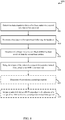
- FIG. 8 is a flowchart of a method 800 for delaying SR triggering following handover in a wireless communications device.
- the method 800 is described below with reference to aspects of one or more of the UEs 115 described with reference to FIGS. 1 , 2A , 2B , 5A , 5B and/or 6.
- a UE 115, or a processor module thereof may execute one or more sets of codes to control the functional elements of the device to perform the functions described below.
- the UE may determine that a handover from a first base station to a second base station has occurred.
- the UE may determine that data is to be transmitted following the handover. Such a determination may be made by determining that there is uplink data in the UE's buffer, for example.
- the UE may determine if a Master Information Block (MIB) has been received from the second base station. If the MIB has not been received, the UE may delay the trigger of the scheduling request for a predetermined time period, as indicated at block 820.
- the UE may determine if second time period has expired.
- MIB Master Information Block
- Such a second time period may be an upper limit for receiving the MIB from the second base station, and may indicate that the UE should declare RLF.
- the UE may initiate a RLF procedure in the absence of a receipt of the MIB within the second predetermined time period.
- a CDMA system may implement a radio technology such as CDMA2000, Universal Terrestrial Radio Access (UTRA), etc.
- CDMA2000 covers IS-2000, IS-95, and IS-856 standards.
- IS-2000 Releases 0 and A are commonly referred to as CDMA2000 IX, IX, etc.
- IS-856 (TIA-856) is commonly referred to as CDMA2000 1xEV-DO, High Rate Packet Data (HRPD), etc.
- UTRA includes Wideband CDMA (WCDMA) and other variants of CDMA.
- a TDMA system may implement a radio technology such as Global System for Mobile Communications (GSM).
- GSM Global System for Mobile Communications
- An OFDMA system may implement a radio technology such as Ultra Mobile Broadband (UMB), Evolved UTRA (E-UTRA), IEEE 802.11 (Wi-Fi), IEEE 802.16 (WiMAX), IEEE 802.20, Flash-OFDM, etc.
- UMB Ultra Mobile Broadband
- E-UTRA Evolved UTRA
- Wi-Fi Wi-Fi
- WiMAX IEEE 802.16
- IEEE 802.20 Flash-OFDM
- UTRA and E-UTRA are part of Universal Mobile Telecommunication System (UMTS).
- 3GPP Long Term Evolution (LTE) and LTE-Advanced (LTE-A) are new releases of UMTS that use E-UTRA.
- UTRA, E-UTRA, UMTS, LTE, LTE-A, and GSM are described in documents from an organization named "3rd Generation Partnership Project" (3GPP).
- CDMA2000 and UMB are described in documents from an organization named "3rd Generation Partnership Project 2" (3GPP2).
- 3GPP2 3rd Generation Partnership Project 2
- the techniques described herein may be used for the systems and radio technologies mentioned above as well as other systems and radio technologies.
- the description above describes an LTE system for purposes of example, and LTE terminology is used in much of the description above, although the techniques are applicable beyond LTE applications.
- Information and signals may be represented using any of a variety of different technologies and techniques.
- data, instructions, commands, information, signals, bits, symbols, and chips that may be referenced throughout the above description may be represented by voltages, currents, electromagnetic waves, magnetic fields or particles, optical fields or particles, or any combination thereof.
- DSP digital signal processor
- ASIC application specific integrated circuit
- FPGA field programmable gate array
- a general-purpose processor may be a microprocessor, but in the alternative, the processor may be any conventional processor, controller, microcontroller, or state machine.
- a processor may also be implemented as a combination of computing devices, e.g., a combination of a DSP and a microprocessor, multiple microprocessors, one or more microprocessors in conjunction with a DSP core, or any other such configuration.
- the functions described herein may be implemented in hardware, software executed by a processor, firmware, or any combination thereof. If implemented in software executed by a processor, the functions may be stored on or transmitted over as one or more instructions or code on a computer-readable medium. Other examples and implementations are within the scope of the appended claims. For example, due to the nature of software, functions described above can be implemented using software executed by a processor, hardware, firmware, hardwiring, or combinations of any of these. Features implementing functions may also be physically located at various positions, including being distributed such that portions of functions are implemented at different physical locations.
- Computer-readable media includes both computer storage media and communication media including any medium that facilitates transfer of a computer program from one place to another.
- a storage medium may be any available medium that can be accessed by a general purpose or special purpose computer.
- computer-readable media can comprise RAM, ROM, EEPROM, CD-ROM or other optical disk storage, magnetic disk storage or other magnetic storage devices, or any other medium that can be used to carry or store desired program code means in the form of instructions or data structures and that can be accessed by a general-purpose or special-purpose computer, or a general-purpose or special-purpose processor.
- any connection is properly termed a computer-readable medium.
- Disk and disc include compact disc (CD), laser disc, optical disc, digital versatile disc (DVD), floppy disk and blu-ray disc where disks usually reproduce data magnetically, while discs reproduce data optically with lasers. Combinations of the above are also included within the scope of computer-readable media.
Landscapes
- Engineering & Computer Science (AREA)
- Computer Networks & Wireless Communication (AREA)
- Signal Processing (AREA)
- Computer Security & Cryptography (AREA)
- Mobile Radio Communication Systems (AREA)
Description
- The following relates generally to wireless communication, and more specifically to scheduling request transmission via a wireless communication device following handover between base stations. Wireless communications systems are widely deployed to provide various types of communication content such as voice, video, packet data, messaging, broadcast, and so on. These systems may be multiple-access systems capable of supporting communication with multiple users by sharing the available system resources (e.g., time, frequency, and power). Examples of such multiple-access systems include code-division multiple access (CDMA) systems, time-division multiple access (TDMA) systems, frequency-division multiple access (FDMA) systems, and orthogonal frequency-division multiple access (OFDMA) systems.
- Generally, a wireless multiple-access communications system may include a number of base stations, each simultaneously supporting communication for multiple mobile devices. Base stations may communicate with mobile devices on downstream and upstream links. Each base station has a coverage range, which may be referred to as the coverage area of the cell. As mobile devices move between coverage areas, a handoff occurs, in which communications with the mobile device are handed off from one base station in an initial coverage area to another base station in another coverage area.
- A handoff procedure often includes exchanging information between the base stations, as well as providing instructions and information to the mobile device related to the handoff. Information exchanged between base stations may include, for example, context information related to data and/or other communications between the initial base station and the mobile device. The mobile device may be instructed that a handover is to be completed via radio resource control (RRC) signaling. In some handover cases, a mobile device may be located at an edge of a base station's coverage area, which may result in reduced signal quality and increased numbers of retransmissions in order to successfully transmit certain communications. In some instances, such retransmissions may result in inefficiencies in the event that a mobile device attempts to take certain actions before transmissions related to handover are successfully received.
- Attention is drawn to the document
US 2008/318578 (A1 ) describing a method for handover of a wireless subscriber communication unit from a first base station to a second base station in a wireless network. The method comprises at the wireless subscriber communication unit receiving a handover command message from the first base station. At the first base station, the method comprises sending a scheduling request message to the second base station, in response to an acknowledgement message sent from the wireless subscriber communication unit. The method further comprises, at the second base station, scheduling, in response to the scheduling request message, at least one uplink scheduling resource (UL-SCH) for the wireless subscriber communication unit to transmit a handover (HO) confirmation message to the second base station; and receiving a handover confirmation message from the wireless subscriber communication unit on the at least one uplink scheduling resource (UL-SCH). - Further attention is drawn to the document
US 2012/040674 (A1 ) which describes a UE that includes a processor configured such that the UE receives one or more wireless signals providing handover synchronization information of a first network component relative to one or more second network components. In another example, a first network component is provided. The first network component includes a processor configured to transmit one or more signals providing handover synchronization information of the first network component relative to one or more second network components. The first network component and the one or more second network components are in different radio access networks. - In accordance with the present invention, a method, apparatus and a non-transitory computer-readable medium, as set forth in the independent claims, is provided. Embodiments of the invention are claimed in the dependent claims.
- The described features generally relate to one or more improved systems, methods, and/or apparatuses for transmitting scheduling requests for uplink transmission resources following a handover. In some examples, a user equipment (UE) may determine that a handover from a first base station to a second base station has occurred, and may implement one or more processes to enhance efficiency in communications following the handover. In some examples, a UE may wait for successful acquisition and/or derivation of timing information from a base station before attempting to request uplink resources from the base station.
- A first aspect of the invention comprises a method of wireless communications using a mobile device, comprising:
- determining that a handover from a first base station to a second base station has occurred; and
- delaying transmission of a scheduling request to the second base station for a predetermined time period based at least on determining an absence, at the mobile device, of receipt of a Master Information Block, MIB, from the second base station following the handover.
- A second aspect of the invention comprises an apparatus of wireless communications, comprising:
- means for determining that a handover from a first base station to a second base station has occurred; and
- means for delaying a transmission of a scheduling request to the second base station for a predetermined time period based at least on determining an absence, at the apparatus, of receipt of a Master Information Block, MIB, from the second base station following the handover.
- A third aspect of the invention comprises a non-transitory computer-readable medium storing computer executable code for wireless communication, the code configured to cause a processor to carry out the steps of any of claims 1 to 10.
- Various embodiments of the method, apparatuses, and/or computer program products may include the features of, means for, and/or processor-executable instructions for determining that a System Information Block (SIB) has been received before the handover has occurred. In some cases, delaying the trigger of the scheduling request includes delaying the trigger of the scheduling request until a condition is satisfied. The condition being satisfied may include receiving a Master Information Block (MIB) from the second base station. In some cases, delaying the trigger of the scheduling request includes delaying the scheduling request for a predetermined time period following the handover. The predetermined time period may correspond to an expected acquisition or an expected derivation of uplink timing through a Master Information Block (MIB) from the second base station. Delaying the trigger of the scheduling request may include determining that data is to be transmitted following the handover, determining if a Master Information Block (MIB) has been received from the second base station, and delaying the trigger of the scheduling request for a predetermined time period. The predetermined time period may correspond to an expected acquisition or an expected derivation of uplink timing through the MIB from the second base station.
- Various embodiments of the method, apparatuses, and/or computer program products may include the features of, means for, and/or processor-executable instructions for determining, after expiration of the predetermined time period, whether the MIB has been received, and further delaying the trigger of the scheduling request for the predetermined time period responsive to determining that the MIB is not received.
- Various embodiments of the method, apparatuses, and/or computer program products may include the features of, means for, and/or processor-executable instructions for triggering the scheduling request responsive to determining that the MIB has been received.
- Various embodiments of the method, apparatuses, and/or computer program products may include the features of, means for, and/or processor-executable instructions for initiating a radio link failure (RLF) procedure in the absence of a receipt of the MIB within a second predetermined time period. In some cases, the predetermined time period corresponds to a predetermined number of Long Term Evolution (LTE) frames.
Further scope of the applicability of the described methods and apparatuses will become apparent from the following detailed description, claims, and drawings. The detailed description and specific examples are given by way of illustration only, since various changes and modifications will become apparent to those skilled in the art. - A further understanding of the nature and advantages of the present invention may be realized by reference to the following drawings. In the appended figures, similar components or features may have the same reference label. Further, various components of the same type may be distinguished by following the reference label by a dash and a second label that distinguishes among the similar components. If only the first reference label is used in the specification, the description is applicable to any one of the similar components having the same first reference label irrespective of the second reference label.
-
FIG. 1 shows an example wireless communications system diagram of mobile devices communicating with multiple base stations according to aspects of the disclosure; -
FIG. 2A shows an example of a mobile device communicating with a first base station prior to a handover, according to aspects of the disclosure; -
FIG. 2B shows an example of a mobile device communicating with a second base station following a handover, according to aspects of the disclosure; -
FIG.3 is a flowchart of a method for requesting UL resources from a target base station according to aspects of the disclosure; -
FIG. 4 is a flowchart of another method for requesting UL resources from a target base station according to aspects of the disclosure; -
FIG. 5A shows a block diagram of an example of a wireless communications device according to aspects of the disclosure; -
FIG. 5B shows a block diagram of another example of a wireless communications device according to aspects of the disclosure; -
FIG. 6 shows a block diagram of a configuration for implementing a UE according to aspects of the disclosure; -
FIG. 7 is a flowchart of a method for wireless communications according to aspects of the disclosure; and -
FIG. 8 is a flowchart of another method for wireless communications according to aspects of the disclosure. - Described embodiments are directed to one or more improved systems, methods, and/or apparatuses for transmitting scheduling requests for uplink transmission resources following a handover. In some aspects of the present disclosure, a user equipment (UE) may determine that a handover from a first base station (e.g., a source base station), to a second base station (e.g., a target base station) has occurred, and may implement one or more processes to enhance efficiency in communications following the handover. In existing deployments, inefficiencies may occur, for example, when a UE tries to initiate an uplink transmission prior to successful acquisition and/or derivation of timing information from a target base station following a handover. In such instances, the UE may initiate a random access procedure using a random access channel (RACH) associated with the target base station. Such a random access procedure may consume additional resources at both the UE and base station, may take significantly longer than a transmission of a scheduling request, which could be transmitted if the UE had the timing information from the target base station. In some examples, following a handover, a UE may wait for timing information to be successfully received and/or derived from a base station before attempting to schedule uplink resources with the base station.
- In certain examples, a UE may wait a predetermined time period following a handover prior to initiating a scheduling request. In other examples, a UE may determine if timing information has been received and/or derived following a handover, and if the timing information is received and/or derived may transmit a scheduling request. In some cases, uplink timing information may be derived from downlink timing, such as from downlink timing information which has been received. If timing information is not received and/or derived, the UE may delay transmitting the scheduling request for a fixed delay period. In some examples, the UE may determine if a master information block (MIB) has been received from the target base station, which contains timing information for the base station. If the MIB has not been received, the UE may wait the fixed delay period prior to sending a scheduling request. A UE, in some examples, may wait the fixed delay period and re-check to determine if the MIB has been received prior to sending the scheduling request. The fixed delay period may, for example, correspond to an expected receipt time for receiving a transmission or retransmission of a MIB from the target base station. In some deployments, a MIB may be transmitted one or more times in a MIB update time period (e.g., 10 ms, etc.), and the fixed delay period may also be set to the MIB update time period in order to allow for successful reception and timing acquisition based on the MIB. In some cases, a random access procedure, such as via a RACH, that is triggered by a pending uplink transmission may be suspended or suppressed, while waiting for reception of the MIB.
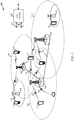
- Referring first to
FIG. 1 , an examplewireless communication system 100 may include a plurality ofUEs 115 that may communicate with acore network 130 via one or more base stations (or cells) 105. Thebase stations 105 may communicate with theUEs 115 under the control of a base station controller (not shown), which may be part of thecore network 130.Base stations 105 andUEs 115 may be referred to generally as wireless communications devices. -
Base stations 105 may communicate control information and/or user data with thecore network 130 through backhaul links 135 (e.g., SI, etc.). In some embodiments, thebase stations 105 may communicate, either directly or indirectly, with each other over backhaul links 125 (e.g., X2, etc.), which may be wired or wireless communication links. Thewireless communication system 100 may support operation on multiple carriers (waveform signals of different frequencies). Multi-carrier transmitters can transmit modulated signals simultaneously on the multiple carriers. For example, each communication link 120 may be a multi-carrier signal modulated according to various radio technologies. Each modulated signal may be sent on a different carrier and may carry control information (e.g., reference signals, control channels, etc.), overhead information, data, etc. - The
base stations 105 may wirelessly communicate with theUEs 115 via one or more base station antennas. Each of thebase station 105 sites may provide communication coverage for a respectivegeographic coverage area 110. In the event that aUE 115 moves betweencoverage areas 110,base stations 105 for the respective coverage areas may initiate a handover of theUE 115 to change whichbase station 105 communicates with theUE 115. AUE 115, as will be discussed in more detail below, may delay certain actions following a handover in some examples, in order to avoid relatively inefficient procedures for initiating uplink communications with abase station 105. - In some embodiments, the
base stations 105 may be referred to as a base transceiver station, a radio base station, an access point, a radio transceiver, a basic service set (BSS), an extended service set (ESS), a NodeB, eNodeB (eNB), Home NodeB, a Home eNodeB, or some other suitable terminology. Thegeographic coverage area 110 for afirst base station 105 may be divided into sectors making up only a portion of the coverage area (not shown). Thewireless communication system 100 may includebase stations 105 of different types (e.g., macro, micro, and/or pico base stations). There may be overlapping coverage areas for different technologies. - The
wireless communication system 100 may support synchronous or asynchronous operation. For synchronous operation, thebase stations 105 may have similar frame timing, and transmissions fromdifferent base stations 105 may be approximately aligned in time. For asynchronous operation, thebase stations 105 may have different frame timing, and transmissions fromdifferent base stations 105 may not be aligned in time. The techniques described herein may be used for either synchronous or asynchronous operations. - The
UEs 115 are dispersed throughout thewireless communication system 100, and eachUE 115 may be stationary or mobile. AUE 115 may also be referred to as a mobile device, a mobile station, a subscriber station, a mobile unit, a subscriber unit, a wireless unit, a remote unit, a UE, a wireless device, a wireless communications device, a remote device, a mobile subscriber station, an access terminal, a mobile terminal, a wireless terminal, a remote terminal, a handset, a user agent, a mobile client, a client, or some other suitable terminology. AUE 115 may be a two-way radio, a radio cellular phone, a personal digital assistant (PDA), a wireless modem, a wireless communication device, a handheld device, a tablet computer, a laptop computer, a cordless phone, a wireless local loop (WLL) station, or the like. - The communication links 120 shown in
wireless communication system 100 may include uplink (UL) and/or downlink (DL) transmissions between aUE 115 and abase station 105. The downlink transmissions may also be called forward link transmissions while the uplink transmissions may also be called reverse link transmissions. The communication links 120 may utilize different air interfaces of different radio access technologies (RATs). - As mentioned above, a
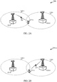
UE 115 may changecoverage areas 110 associated withdifferent base stations 105. Turning now toFIG. 2A , handover in an examplewireless communication system 200 is discussed in accordance with various examples. Thewireless communication system 200 may be an example of thewireless communication system 100 described above with reference toFIG. 1 . In this example, a UE 115-a may initially be within coverage area 110-a of base station 105-a. The UE 115-a may communicate with base station 105-a usingcommunication link 205. As illustrated inFIG. 2A , the UE 115-a may be close to an edge of coverage area 110-a, and also be within coverage area 110-b of a second base station 105-b. - At some point, the UE 115-a and/or base station 105-a may determine that it is desirable for the UE 115-a to be handed over to base station 105-b. Such a determination may be made according to a number of factors that are well known in the art. For example, measurement reports from UE 115-a may indicate that a handover may be desirable. Of course, as will be readily recognized by one of skill in the art, numerous other factors may be taken into account in making a handover decision, such as movement of UE 115-a and/or loading at base station 105-a, to name but two examples. Once a handover decision is made, base station 105-a may initiate a handover with a handover request transmitted to base station 105-b. Base station 105-b may acknowledge the handover request and base station 105-a may transfer various items of information (e.g., sequence number status information, user plane data, etc.) to base station 105-b to help enable a seamless transition of UE 115-a from source base station 105-a to target base station 105-b. An RRC connection reconfiguration may be transmitted to UE 115-a, and the UE 115-a may initiate a connection with base station 105-b.
-
FIG. 2B illustrates an example wireless communication system 200-a in which UE 115-a is handed over to target base station 105-b. The UE 115-a may communicate with base station 105-b following handover usingcommunication link 210. As illustrated inFIG. 2B , the UE 115-a may be close to an edge of coverage area 110-b of base station 105-b. In such cases, UE 115-a may have relatively weak signal reception usingcommunication link 210, which may result in a relatively high number of retransmissions of data before successful receipt of the data at UE 115-a. As part of the handover process, UE 115-a acquires and/or derives timing information of the target base station 105-b in order to have synchronized communications with target base station 105-b via communications link 210. Such timing information may be acquired through the reception and decoding of a master information block (MIB) that is transmitted by target base station 105-b. The MIB may be transmitted by target base station 105-b on a periodic basis, such as once per LTE frame (i.e., once every 10 ms). - In situations where UE 115-a may be close to an edge of coverage area 110-b, it is possible that the UE 115-a may not successfully receive and decode the MIB from target base station 105-b during the first transmission of the MIB following the handover. Thus, UE 115-a may need to receive one or more additional transmissions of the MIB in order to successfully receive and decode the MIB. In such cases, the UE 115-a may not have all of the timing information for initiating communications with the target base station 105-b until the MIB is successfully received and decoded.
- However, as mentioned above, in some cases UE 115-a may determine that there is data in the UE's buffer that is to be transmitted. In such cases, the UE 115-a may transmit a scheduling request (SR) to the target base station 105-b to initiate an uplink transmission of the data in the UE 115-b buffer. In cases where UE 115-a has not successfully acquired and/or derived timing information for the target base station 105-b, the UE 115-a may initiate a random access procedure to access the target base station 105-b. As noted above, such a random access procedure can be resource intensive and relatively inefficient. Accordingly, according to various examples, the UE 115-a may suppress or suspend a random access procedure that may otherwise be triggered by the pending uplink transmission. The UE 115-a may wait for a certain time period, or for a certain condition to be satisfied, following handover prior to initiating uplink communications with target base station 105-b. Such a delay may be implemented according a number of techniques, as will be discussed in more detail below.
-
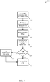
FIG. 3 shows a flowchart of amethod 300 for reducing payload size for a wireless communications device according to aspects of the disclosure. Themethod 300 may be implemented by one or more of theUEs 115 ofFIGS. 1 ,2A , and/or 2B. Additionally or alternatively, the operations of themethod 300 may be performed by theUEs 115 described below with reference toFIGS. 5A ,5B , and/or 6. - At
block 305, the UE is in an RRC connected with a source eNB. For example, aUE 115 of one of the preceding figures may be RRC connected with afirst base station 105 of one of the preceding figures. Atblock 310, a handover process in executed to target eNB. For example, aUE 115 of the preceding figures may be handed over to atarget base station 105 of one of the preceding figures. Following the initiation of the handover process, the UE may determine that there was a failure in the acquisition of the MIB from the target eNB, as indicated atblock 315. Atblock 320, there is data arrival at the UE buffer for an uplink transmission. In this example, rather than initiate the uplink transmission immediately by triggering a SR, causing an ultimately a random access procedure to be triggered due to lack of timing information, the UE determines if the MIB has been acquired, as indicated atblock 325. - If the MIB has been not acquired, the UE waits a predetermined time, as indicated at
block 330. In some examples, the predetermined time period corresponds to an expected time of receipt of another transmission from the target eNB that contains the MIB or timing information. For example, in an LTE system where an eNB transmits a MIB once per LTE frame, the predetermined time period may be 10 ms. In other examples, the predetermined time period may provide sufficient time to receive two or more transmission of timing information. Following the expiration of the predetermined time period, or if the MIB has been acquired as determined atblock 325, the UE may transmit a SR to the eNB, as indicated atblock 335. In such a manner, the UE may avoid an unnecessary random access procedure, and initiate the uplink data transmission more efficiently and more quickly than if a random access procedure had been initiated. While the example ofFIG. 3 describes that the UE determines if a MIB has been acquired, in further examples a UE may simply wait a predetermined time period following a handover prior to triggering a SR (rather than determine if a MIB is acquired). In some cases, the UE may trigger a SR after a condition is satisfied, such as a MIB is acquired, and may not wait for a System Information Block (SIB), which may be received before handover and/or after the MIB, to trigger the SR. - In still further examples, a UE may dynamically determine an amount of time to wait prior to triggering a SR.
FIG. 4 shows a flowchart of amethod 400 of such an example for delaying the trigger of a SR. Themethod 400 may be implemented by one or more of theUEs 115 of the precedingfigures 1 ,2A , and/or 2B. Additionally or alternatively, the operations of themethod 400 may be performed by theUEs 115 described with reference toFIGS. 5A ,5B , and/or 6. - At
block 405, the UE is in an RRC connected with a source eNB. For example, aUE 115 of one of the preceding figures may be RRC connected with afirst base station 105 of one of the preceding figures. Atblock 410, a handover process in executed to target eNB. For example, aUE 115 of the preceding figures may be handed over to atarget base station 105 of one of the preceding figures. Atblock 415, there is data arrival at the UE buffer for an uplink transmission. In this example, the UE determines if the MIB has been acquired, as indicated atblock 420. If the MIB has been acquired, the UE transmits a SR to the eNB, as indicated atblock 425. - If the MIB has not been acquired, in the example of
FIG. 4 , the UE may determine if an MIB acquisition period has expired, as indicated atblock 430. Such a time period may be a second predetermined time period, and may indicate that the UE is not able to reliably receive communications from the target eNB. In such a case, the UE may declare a radio link failure (RLF), as indicated atblock 440. Following RLF, the UE may enter into a reestablishment process and attempt to establish a connection with a different or same eNB, for example. If the MIB acquisition period has not expired, the UE waits the predetermined time period (e.g., 10 ms, similarly as described above), as indicated atblock 435, and operations ofblock 420 are repeated. In such a manner, a SR is not triggered until the MIB has been received at the UE. In such a manner, the UE may avoid an unnecessary random access procedure, and initiate the uplink data transmission more efficiently and more quickly than if a random access procedure had been initiated. In some cases, the UE may trigger a SR after a condition is satisfied, such as a MIB is acquired, and may not wait for a System Information Block (SIB), which may be received before handover and/or after the MIB, to trigger the SR. -
FIG. 5A shows a block diagram 500-a of an example of UE 115-b according to various aspects of the disclosure. The UE 115-b may be an example of one or more aspects of aUE 115 orbase station 105 ofFIGS. 1 ,2A , and/or 2B, for example. The UE 115-b may include areceiver module 510, atransmitter module 520, aSR trigger module 515, and a handover (HO) management module 535. The UE 115-b may also include a processor (not shown), which may be part of theSR trigger module 515, for example. Each of these components may be in communication with each other. - The
receiver module 510 may receive information such as packets, user data, and/or control information including headers, synchronization and pilot signals. The received information may be demodulated, descrambled, de-interleaved, and/or decoded. The information may be passed on to theSR trigger module 515, theHO management module 517, and to other components of the UE 115-b as appropriate or desired. - The
receiver module 510 may include a single receiver or multiple receivers. For example, thereceiver module 510 may include N receive antennas and R RF chains (not shown), where R is generally less than or equal to N. Each RF chain may include an RF module and an analog-to-digital converter (ADC). During operation, signals received by a receive antenna may be provided to an input of an RF chain. At the RF chain, the signals are processed (e.g., amplified, downconverted, filtered, etc.) by an RF module and digitized by the ADC. The output of the RF chain may be provided to the demodulator for further processing. The demodulator may combine signals received from multiple antennas using receive diversity techniques to increase the SINR of the received signals. The demodulator may use a suitable signal combining technique such as equal gain combining, maximum ratio combining (MRC), and the like. The demodulator and RF chains may use interference cancellation techniques to further provide interference cancellation and/or suppression (e.g., interference rejection combining, successive interference cancellation, and the like). - The
transmitter module 520 may transmit information such as packets, user data, and/or control information including headers, synchronization and pilot signals. The transmitted information may be modulated, scrambled, interleaved, and/or coded. The information may be received from theSR trigger module 515, theHO management module 517, and from other components of the UE 115-b as appropriate or desired. In some embodiments, thetransmitter module 520 may be collocated with thereceiver module 510 in a transceiver module (not shown). Thetransmitter module 520 may include a single antenna, or it may include a plurality of antennas. - The
SR trigger module 515 may employ thetransmitter module 520 and the receiver module 510 (or a transceiver module) to trigger and transmit a scheduling request, as described herein. Further, theSR trigger module 515 may prepare a scheduling request, and/or determine whether a condition has been satisfied to trigger a scheduling request, such as an event based condition or a time based condition, as described herein. - The
HO management module 517 may employ thetransmitter module 520 and the receiver module 510 (or a transceiver module) to determine that handover has occurred or is going to occur, determine that there is uplink data for transmission, suspend or suppress a random access procedure to a target base station that may be triggered based on the pending uplink transmission prior to receiving uplink timing information for the target base station, and receive information from theSR trigger module 515 related to the event or time-based condition. In some examples, theHO management module 517 may initiate a radio link failure (RLF) procedure such as if a MIB is not received, as described herein. - The components of the UE 115-b may, individually or collectively, be implemented using one or more ASICs adapted to perform some or all of the applicable functions in hardware. Alternatively, the functions may be performed by one or more other processing units (or cores), on one or more integrated circuits. In other examples, other types of integrated circuits may be used (e.g., Structured/Platform ASICs, FPGAs, and other Semi-Custom ICs), which may be programmed in any manner known in the art. The functions of each component may also be implemented, in whole or in part, with instructions embodied in a memory, formatted to be executed by one or more general or application-specific processors.
-
FIG. 5B shows a block diagram 500-b of an example of a UE 115-c. The UE 115-c may be an example of one or more aspects of aUE 115 described with reference toFIGS. 1 ,2A, 2B , and/or 5A. The UE 115-c may include areceiver module 510, atransmitter module 520, a SR trigger module 515-a, a HO management module 517-a, and aninformation block module 525. The UE 115-c may also include a processor (not shown), which may be part of the SR trigger module 515-a, the HO management module 517-a, and/or theinformation block module 525, for example. Each of these components may be in communication with each other. - The
receiver module 510 and thetransmitter module 520 may be configured and may be employed as described above with respect toFIG. 5A . The SR trigger module 515-a may be configured and may implement operations as described above with respect to theSR trigger module 515 ofFIG. 5A . The HO management module 517-a may be configured and may implement operations as described above with respect to theHO management module 517 ofFIG. 5A . - Further, as illustrated in
FIG. 5B , the UE 115-c may include aninformation block module 525. Theinformation block module 525 may determine whether an information block (e.g., MIB, SIB, etc.) has been received from a target base station, for example. In some cases, theinformation block module 525 determines that a SIB has been received, such as before a handover. In some examples, theinformation block module 525 determines whether an event based condition has been satisfied, such as reception of a MIB, reception of a SIB, and the like. - The SR trigger module 515-a may include a
timing module 530. Thetiming module 530 may perform timing operations. Thetiming module 530 may determine whether a time based condition has been satisfied, such as expiration of a predetermined time period. Thetiming module 530 may determine one or more predetermined time periods, such as based on a predetermined number of Long Term Evolution (LTE) frames or subframes, an expected acquisition of timing for a target base station (e.g., via information in a MIB, etc.), and/or an expected derivation of timing for a target base station (e.g., via detection and/or decoding of a MIB, etc.). In some cases, thetiming module 530 may wait a predetermined time period, such as to either trigger a SR, or determine if a MIB has been received, such as described above. In some examples, the timing module may be configured to time a second predetermined time period that may be used to declare a RLF in the event that the MIB has not been received within the second predetermined time period, such as described above. -
FIG. 6 shows a block diagram 600 of a configuration for implementing a UE 115-d. The UE 115-d may be an example of one or more aspects ofUEs 115 described with reference toFIGS. 1 ,2A ,2B ,5A , and/or 5B. The UE 115-d may have an internal power supply (not shown), such as a small battery, to facilitate mobile operation. The UE 115-d may include one ormore antennas 605 configured to receive and transmit wireless signals in cooperation with one ormore transceiver modules 610. The UE 115-d may further include a SR trigger module 515-b,, a HO management module 517-b, an information block module 525-a, aprocessor module 625, acommunications management module 630, input/output (I/O)devices 635, and amemory 615, each of which may be in communication, directly or indirectly, with each other (e.g., over one or more buses 650). - The
transceiver module 610 may be configured to communicate, such as bidirectionally via the antenna(s) 605, with other UEs and/or base stations of one or more networks. Thus, thetransceiver module 610 or transceiver may be means for sending, transmitting, receiving and/or determining, alone or in combination with the various other modules of the UE 115-d and/or the antenna(s) 605. Thetransceiver module 610 may include a modem configured to modulate the packets and provide the modulated packets to the antenna(s) 605 for transmission, and to demodulate packets received from the antenna(s) 605. Thetransceiver module 610 may be implemented as at least one transmitter module and at least one separate receiver module. While the UE 115-d may include a single antenna, there may be aspects in which the UE 115-d may includemultiple antennas 605. - The
memory 615 may include random access memory (RAM) and read-only memory (ROM). Thememory 615 may also store computer-readable, computer-executable software code 620 containing instructions that are configured to, when executed, cause theprocessor module 625 to perform various functions described herein (e.g., delaying triggering of a SR, etc.). Alternatively, thesoftware code 620 may not be directly executable by theprocessor module 625, but may be configured to cause a computer, e.g., when compiled and executed, to perform functions described herein. Thus, theprocessor module 625 or processor may be means for initiating, establishing, starting, transmitting, monitoring restarting, setting, incrementing, resetting, determining, etc., alone or in combination with thememory 615 and thesoftware code 620. Theprocessor module 625 may include an intelligent hardware device, e.g., a central processing unit (CPU), a microcontroller, an application-specific integrated circuit (ASIC), etc. Theprocessor module 625 may process information received through thetransceiver module 610 and/or to be sent to thetransceiver module 610 for transmission through the antenna(s) 605. - The one or more input/output (I/O)
devices 635 may include one or more devices for receiving user input (e.g., buttons, keyboard, mouse, trackpad, touch-screen, microphone, etc.), sensing information (e.g., Global Positioning System (GPS) devices, gyroscopes, accelerometers, piezoelectric sensors, etc.), providing output to a user (e.g., display devices, speakers, motors, actuators, etc.), and/or other communication interfaces (e.g., infra-red communication devices, near-field communications (NFC) devices, etc.). - The SR trigger module 515-b may be configured to perform various monitoring, detecting, or determining operations as described herein. The SR trigger module 515-b may perform such operations in conjunction with the
transceiver 610 and the antenna(s) 605. Further, the SR trigger module 515-b may operate under the control of theprocessor module 625. The SR trigger module 515-b may be an example of theSR trigger modules 515 ofFIGS. 5A and/or 5B, and may implement the functionality for these modules described above. - The HO management module 517-b may be configured to perform various monitoring, detecting, or determining operations as described herein. The HO management module 517-b may perform such operations in conjunction with the
transceiver 610 and the antenna(s) 605. Further, the HO management module 517-b may operate under the control of theprocessor module 625. The HO management module 517-b may be an example of theHO management modules 517 ofFIGS. 5A and/or 5B, and may implement the functionality for these modules described above. - The information block module 525-a may be configured to perform various monitoring, detecting, or determining operations as described herein. The information block module 525-a may perform such operations in conjunction with the
transceiver 610 and the antenna(s) 605. Further, the information block module 525-a may operate under the control of theprocessor module 625. The information block module 525-a may be an example of theinformation block module 525 ofFIGS. 5B , and may implement the functionality for this module described above. Although the SR trigger module 515-b, HO management module 517-b, and information block module 525-a are shown separately, the functionality of the SR trigger module 515-b, HO management module 517-b, and/or information block module 525-a may be implemented as a component of thetransceiver module 610, thecommunications management module 630, as a computer program product, and/or as one or more controller elements of theprocessor module 625. - The UE 115-d may further include a
communications management module 630, which may be configured to manage or otherwise control various communication operations of the UE 115-d, such as according to various radio protocols including operation on LTE/LTE-A networks. In particular, thecommunications management module 630 may support operations of the HO management module 517-b, the SR trigger module 515-b, and/or the information block module 525-a that involve determining if uplink timing information for a target base station has been acquired and/or derived after handover, delaying the triggering for uplink scheduling requests based on uplink timing acquisition, and suppression of a random access procedure as described above. - According to the architecture of
FIG. 6 , the HO management module 517-b, the SR trigger module 515-b, the information block module 525-a, and/or thecommunications management module 630 may be components of the UE 115-d in communication with some or all of the other components of the UE 115-d over the at least onebus 650. Additionally or alternatively, some or all of the various described functionality of these modules may be implemented as one or more components of thetransceiver module 610, as a computer program product, as instructions embodied in one or more functions, subroutines, classes, modules, and/or packages ofsoftware code 620, and/or as one or more controller elements of theprocessor module 625. - The components of the UE 115-d may, individually or collectively, be implemented with one or more application-specific integrated circuits (ASICs) adapted to perform some or all of the applicable functions in hardware. Alternatively, the functions may be performed by one or more other processing units (or cores), on one or more integrated circuits. In other embodiments, other types of integrated circuits may be used (e.g., Structured/Platform ASICs, Field Programmable Gate Arrays (FPGAs), and other Semi-Custom ICs), which may be programmed in any manner known in the art. The functions of each unit may also be implemented, in whole or in part, with instructions embodied in a memory, formatted to be executed by one or more general or application-specific processors. Each of the noted modules may be a means for performing one or more functions related to operation of the UE 115-d.
-
FIG. 7 is a flowchart of amethod 700 for delaying SR triggering following handover in a wireless communications device. For clarity, themethod 700 is described below with reference to aspects of one or more of theUEs 115 described with reference toFIGS. 1 ,2A ,2B ,5A ,5B and/or 6. In one implementation, aUE 115, or a processor module thereof, may execute one or more sets of codes to control the functional elements of the device to perform the functions described below. - At
block 705, the UE may determine that a handover from a first base station to a second base station has occurred. Atblock 710, the UE may delay a trigger of a scheduling request following the handover. Such determination of a handover, and delay of triggering a SR may be performed as described above, according to various examples. For example, the SR may be delayed by a predetermined time period following a handover, may be delayed by a predetermined time period when it is determined that a MIB has not been successfully decoded, or may be dynamically delayed until a MIB is successfully decoded from the second base station, such as discussed above. -
FIG. 8 is a flowchart of amethod 800 for delaying SR triggering following handover in a wireless communications device. For clarity, themethod 800 is described below with reference to aspects of one or more of theUEs 115 described with reference toFIGS. 1 ,2A ,2B ,5A ,5B and/or 6. In one implementation, aUE 115, or a processor module thereof, may execute one or more sets of codes to control the functional elements of the device to perform the functions described below. - At
block 805, the UE may determine that a handover from a first base station to a second base station has occurred. Atblock 810, the UE may determine that data is to be transmitted following the handover. Such a determination may be made by determining that there is uplink data in the UE's buffer, for example. Atblock 815, the UE may determine if a Master Information Block (MIB) has been received from the second base station. If the MIB has not been received, the UE may delay the trigger of the scheduling request for a predetermined time period, as indicated atblock 820. Atoptional block 825, the UE may determine if second time period has expired. Such a second time period may be an upper limit for receiving the MIB from the second base station, and may indicate that the UE should declare RLF. Atblock 830, the UE may initiate a RLF procedure in the absence of a receipt of the MIB within the second predetermined time period. - Techniques described herein may be used for various wireless communications systems such as CDMA, TDMA, FDMA, OFDMA, SC-FDMA, and other systems. The terms "system" and "network" are often used interchangeably. A CDMA system may implement a radio technology such as CDMA2000, Universal Terrestrial Radio Access (UTRA), etc. CDMA2000 covers IS-2000, IS-95, and IS-856 standards. IS-2000 Releases 0 and A are commonly referred to as CDMA2000 IX, IX, etc. IS-856 (TIA-856) is commonly referred to as CDMA2000 1xEV-DO, High Rate Packet Data (HRPD), etc. UTRA includes Wideband CDMA (WCDMA) and other variants of CDMA. A TDMA system may implement a radio technology such as Global System for Mobile Communications (GSM). An OFDMA system may implement a radio technology such as Ultra Mobile Broadband (UMB), Evolved UTRA (E-UTRA), IEEE 802.11 (Wi-Fi), IEEE 802.16 (WiMAX), IEEE 802.20, Flash-OFDM, etc. UTRA and E-UTRA are part of Universal Mobile Telecommunication System (UMTS). 3GPP Long Term Evolution (LTE) and LTE-Advanced (LTE-A) are new releases of UMTS that use E-UTRA. UTRA, E-UTRA, UMTS, LTE, LTE-A, and GSM are described in documents from an organization named "3rd Generation Partnership Project" (3GPP). CDMA2000 and UMB are described in documents from an organization named "3rd Generation Partnership Project 2" (3GPP2). The techniques described herein may be used for the systems and radio technologies mentioned above as well as other systems and radio technologies. The description above, however, describes an LTE system for purposes of example, and LTE terminology is used in much of the description above, although the techniques are applicable beyond LTE applications.
- Thus, the foregoing description provides examples, and is not limiting of the scope, applicability, or configuration set forth in the claims. Changes may be made in the function and arrangement of elements discussed. Various embodiments may omit, substitute, or add various procedures or components as appropriate. For instance, the methods described may be performed in an order different from that described, and various steps may be added, omitted, or combined. Also, features described with respect to certain embodiments may be combined in other embodiments.
- The detailed description set forth above in connection with the appended drawings describes exemplary embodiments and does not represent the only embodiments that may be implemented or that are within the scope of the claims. The term "exemplary" used throughout this description means "serving as an example, instance, or illustration," and not "preferred" or "advantageous over other embodiments." The detailed description includes specific details for the purpose of providing an understanding of the described techniques. These techniques, however, may be practiced without these specific details. In some instances, well-known structures and devices are shown in block diagram form in order to avoid obscuring the concepts of the described embodiments.
- Information and signals may be represented using any of a variety of different technologies and techniques. For example, data, instructions, commands, information, signals, bits, symbols, and chips that may be referenced throughout the above description may be represented by voltages, currents, electromagnetic waves, magnetic fields or particles, optical fields or particles, or any combination thereof.
- The various illustrative blocks and modules described in connection with the disclosure herein may be implemented or performed with a general-purpose processor, a digital signal processor (DSP), an application specific integrated circuit (ASIC), a field programmable gate array (FPGA) or other programmable logic device, discrete gate or transistor logic, discrete hardware components, or any combination thereof designed to perform the functions described herein. A general-purpose processor may be a microprocessor, but in the alternative, the processor may be any conventional processor, controller, microcontroller, or state machine. A processor may also be implemented as a combination of computing devices, e.g., a combination of a DSP and a microprocessor, multiple microprocessors, one or more microprocessors in conjunction with a DSP core, or any other such configuration.
- The functions described herein may be implemented in hardware, software executed by a processor, firmware, or any combination thereof. If implemented in software executed by a processor, the functions may be stored on or transmitted over as one or more instructions or code on a computer-readable medium. Other examples and implementations are within the scope of the appended claims. For example, due to the nature of software, functions described above can be implemented using software executed by a processor, hardware, firmware, hardwiring, or combinations of any of these. Features implementing functions may also be physically located at various positions, including being distributed such that portions of functions are implemented at different physical locations. Also, as used herein, including in the claims, "or" as used in a list of items prefaced by "at least one of' indicates a disjunctive list such that, for example, a list of "at least one of A, B, or C" means A or B or C or AB or AC or BC or ABC (i.e., A and B and C).
- Computer-readable media includes both computer storage media and communication media including any medium that facilitates transfer of a computer program from one place to another. A storage medium may be any available medium that can be accessed by a general purpose or special purpose computer. By way of example, and not limitation, computer-readable media can comprise RAM, ROM, EEPROM, CD-ROM or other optical disk storage, magnetic disk storage or other magnetic storage devices, or any other medium that can be used to carry or store desired program code means in the form of instructions or data structures and that can be accessed by a general-purpose or special-purpose computer, or a general-purpose or special-purpose processor. Also, any connection is properly termed a computer-readable medium. For example, if the software is transmitted from a website, server, or other remote source using a coaxial cable, fiber optic cable, twisted pair, digital subscriber line (DSL), or wireless technologies such as infrared, radio, and microwave, then the coaxial cable, fiber optic cable, twisted pair, DSL, or wireless technologies such as infrared, radio, and microwave are included in the definition of medium. Disk and disc, as used herein, include compact disc (CD), laser disc, optical disc, digital versatile disc (DVD), floppy disk and blu-ray disc where disks usually reproduce data magnetically, while discs reproduce data optically with lasers. Combinations of the above are also included within the scope of computer-readable media.
- The previous description of the disclosure is provided to enable a person skilled in the art to make or use the disclosure. Various modifications to the disclosure will be readily apparent to those skilled in the art, and the generic principles defined herein may be applied to other variations without departing from the scope as defined in the appended claims. Throughout this disclosure the term "example" or "exemplary" indicates an example or instance and does not imply or require any preference for the noted example. Thus, the disclosure is not to be limited to the examples and designs described herein but is to be accorded the widest scope consistent with the attached appended claims.
Claims (15)
- A method (800) of wireless communications using a mobile device, comprising:determining (805) that a handover from a first base station (105-a) to a second base station (105-b) has occurred; and characterized bydelaying (820) transmission of a scheduling request to the second base station (105-b) for a predetermined time period based at least on determining (815) an absence, at the mobile device, of receipt of a Master Information Block, MIB, from the second base station (105-b) following the handover.
- The method (800) of claim 1, wherein the delaying the transmission of the scheduling request comprises:
delaying the transmission of the scheduling request until a condition is satisfied. - The method (800) of claim 2, wherein the condition being satisfied comprises:
receiving the MIB from the second base station (105-b). - The method (800) of claim 1, further comprising:
determining that a System Information Block, SIB, has been received before the handover has occurred. - The method (800) of claim 1, wherein the predetermined time period corresponds to an expected acquisition or an expected derivation of uplink timing through the MIB from the second base station (105-b).
- The method (800) of claim 5, further comprising:
determining (810) that data is to be transmitted to the second base station (105-b) following the handover. - The method (800) of claim 6, further comprising:Determining , after expiration of the predetermined time period, whether the MIB has been received; andfurther delaying the transmission of the scheduling request for the predetermined time period responsive to determining that the MIB has not been received after expiration of the predetermined time period.
- The method (800) of claim 7, further comprising:
transmitting the scheduling request responsive to determining that the MIB has been received. - The method (800) of claim 7, further comprising:
initiating (830) a radio link failure, RLF, procedure in the absence of a receipt of the MIB within a second predetermined time period. - The method (800) of claim 6, wherein the predetermined time period corresponds to a predetermined number of Long Term Evolution, LTE frames.
- An apparatus (600) of wireless communications, comprising:means for determining (517-b) that a handover from a first base station (105-a) to a second base station (105-b) has occurred; and characterized bymeans for delaying (515-b) a transmission of a scheduling request to the second base station (105-b) for a predetermined time period based at least on determining an absence, at the apparatus, of receipt of a Master Information Block, MIB, from the second base station (105-b) following the handover.
- The apparatus (600) of claim 11, wherein the means for delaying the transmission of the scheduling request are configured to delay the scheduling request until a MIB has been received from the second base station (105-b).
- The apparatus (600) of claim 11, further comprising:
means for determining that a System Information Block, SIB, has been received before the handover has occurred. - The apparatus (600) of claim 11, wherein the predetermined time period corresponds to an expected acquisition or an expected derivation of uplink timing through a MIB from the second base station (105-b).
- A non-transitory computer-readable medium storing computer executable code for wireless communication, the code configured to cause a processor to carry out the steps of any of claims 1 to 10.
Applications Claiming Priority (3)
| Application Number | Priority Date | Filing Date | Title |
|---|---|---|---|
| US201461970340P | 2014-03-25 | 2014-03-25 | |
| US14/463,085 US9554308B2 (en) | 2014-03-25 | 2014-08-19 | Delaying a trigger of a scheduling request after handover |
| PCT/US2015/020685 WO2015148164A1 (en) | 2014-03-25 | 2015-03-16 | Delaying a trigger of a scheduling request after handover |
Publications (2)
| Publication Number | Publication Date |
|---|---|
| EP3123775A1 EP3123775A1 (en) | 2017-02-01 |
| EP3123775B1 true EP3123775B1 (en) | 2019-05-01 |
Family
ID=54192424
Family Applications (1)
| Application Number | Title | Priority Date | Filing Date |
|---|---|---|---|
| EP15717287.5A Active EP3123775B1 (en) | 2014-03-25 | 2015-03-16 | Delaying a trigger of a scheduling request after handover |
Country Status (6)
| Country | Link |
|---|---|
| US (1) | US9554308B2 (en) |
| EP (1) | EP3123775B1 (en) |
| JP (1) | JP2017509256A (en) |
| KR (1) | KR101817458B1 (en) |
| CN (1) | CN106105313B (en) |
| WO (1) | WO2015148164A1 (en) |
Families Citing this family (6)
| Publication number | Priority date | Publication date | Assignee | Title |
|---|---|---|---|---|
| US9769733B2 (en) | 2015-02-10 | 2017-09-19 | Qualcomm Incorporated | Incremental transmission of system information |
| US10616822B2 (en) | 2015-02-10 | 2020-04-07 | Qualcomm Incorporated | System information updating |
| US10200920B2 (en) | 2015-02-10 | 2019-02-05 | Qualcomm Incorporated | On-demand system information |
| CN108141815A (en) * | 2015-08-14 | 2018-06-08 | 瑞典爱立信有限公司 | System information broadcast in wireless network |
| US10945162B2 (en) * | 2016-09-30 | 2021-03-09 | Kyocera Corporation | Special uplink subframe for enhanced mobility |
| KR20210095457A (en) * | 2020-01-23 | 2021-08-02 | 삼성전자주식회사 | Method and apparatus for edge computing service |
Family Cites Families (16)
| Publication number | Priority date | Publication date | Assignee | Title |
|---|---|---|---|---|
| US8185726B2 (en) * | 2006-04-27 | 2012-05-22 | Qualcomm Incorporated | Sleep optimization based on system information block scheduling |
| US9307464B2 (en) * | 2007-06-21 | 2016-04-05 | Sony Corporation | Cellular communication system, apparatus and method for handover |
| KR20090006708A (en) * | 2007-07-12 | 2009-01-15 | 엘지전자 주식회사 | Method for transmitting scheduling request signal |
| US8457618B2 (en) | 2008-06-20 | 2013-06-04 | Motorola Mobility Llc | Preventing random access based on outdated system information in a wireless communication system |
| WO2010053159A1 (en) * | 2008-11-07 | 2010-05-14 | 株式会社エヌ・ティ・ティ・ドコモ | Mobile station and mobile communication method |
| US8666389B2 (en) | 2009-08-05 | 2014-03-04 | Htc Corporation | Method of handling system information reception with measurement gap configuration and related communication device |
| WO2011035420A1 (en) * | 2009-09-25 | 2011-03-31 | Research In Motion Limited | System and method for multi-carrier network operation |
| US8559397B2 (en) | 2009-11-19 | 2013-10-15 | Samsung Electronics Co., Ltd. | Handover-related radio link failure detection |
| US20110268085A1 (en) | 2009-11-19 | 2011-11-03 | Qualcomm Incorporated | Lte forward handover |
| JP2011155336A (en) | 2010-01-26 | 2011-08-11 | Sharp Corp | Communication system, mobile station device, base station device, and processing method |
| US8923208B2 (en) * | 2010-08-05 | 2014-12-30 | Qualcomm Incorporated | Multi-radio coexistence |
| US8676206B2 (en) * | 2010-08-13 | 2014-03-18 | Blackberry Limited | Handover latency reduction |
| PT2724561T (en) | 2011-06-21 | 2017-02-21 | ERICSSON TELEFON AB L M (publ) | Methods and apparatuses for performing measurements in a wireless network |
| JP2013055393A (en) * | 2011-09-01 | 2013-03-21 | Sony Corp | Communication device, communication method, communication system, and base station |
| WO2013068364A1 (en) * | 2011-11-08 | 2013-05-16 | Koninklijke Kpn N.V. | Distribution of system information in a wireless access telecommunications system |
| EP2661138A1 (en) | 2012-05-04 | 2013-11-06 | Panasonic Corporation | Threshold-based and power-efficient scheduling request procedure |
-
2014
- 2014-08-19 US US14/463,085 patent/US9554308B2/en active Active
-
2015
- 2015-03-16 JP JP2016558193A patent/JP2017509256A/en not_active Ceased
- 2015-03-16 EP EP15717287.5A patent/EP3123775B1/en active Active
- 2015-03-16 CN CN201580015542.9A patent/CN106105313B/en not_active Expired - Fee Related
- 2015-03-16 WO PCT/US2015/020685 patent/WO2015148164A1/en active Application Filing
- 2015-03-16 KR KR1020167027488A patent/KR101817458B1/en active IP Right Grant
Non-Patent Citations (1)
| Title |
|---|
| None * |
Also Published As
| Publication number | Publication date |
|---|---|
| JP2017509256A (en) | 2017-03-30 |
| CN106105313B (en) | 2018-01-02 |
| US20150282207A1 (en) | 2015-10-01 |
| US9554308B2 (en) | 2017-01-24 |
| CN106105313A (en) | 2016-11-09 |
| KR20160138445A (en) | 2016-12-05 |
| KR101817458B1 (en) | 2018-01-11 |
| EP3123775A1 (en) | 2017-02-01 |
| WO2015148164A1 (en) | 2015-10-01 |
Similar Documents
| Publication | Publication Date | Title |
|---|---|---|
| US11805460B2 (en) | Dual link handover | |
| EP3501238B1 (en) | Energy-efficient paging in wireless networks | |
| EP3123775B1 (en) | Delaying a trigger of a scheduling request after handover | |
| EP3100546B1 (en) | Switching mode of operation in d2d communications | |
| EP3167684B1 (en) | Group priority handling for direct mode resource pools in wireless communications | |
| JP6749841B2 (en) | Time hopping in device-to-device transmission | |
| EP3069552B1 (en) | Priority management of a measurement event timer and low-power period | |
| WO2022067651A1 (en) | Methods and apparatuses for a relay reselection and data transmission handling procedure in a ue-to-network relay scenario | |
| EP3146769B1 (en) | Distributed device-to-device synchronization | |
| US10338660B2 (en) | Method and apparatus for dynamic sleep mode based on predicted communication activity | |
| WO2022061818A1 (en) | Methods and apparatuses for relay reselection and connection handling procedure in ue-to-ue relay scenario | |
| WO2016014219A1 (en) | Monitoring periods for device-to-device synchronization signals | |
| WO2015134224A1 (en) | Context establishment in marginal grant conditions | |
| WO2015074245A1 (en) | Adaptive timer for optimized inter radio access technology switching delay in dual radio device |
Legal Events
| Date | Code | Title | Description |
|---|---|---|---|
| STAA | Information on the status of an ep patent application or granted ep patent |
Free format text: STATUS: THE INTERNATIONAL PUBLICATION HAS BEEN MADE |
|
| PUAI | Public reference made under article 153(3) epc to a published international application that has entered the european phase |
Free format text: ORIGINAL CODE: 0009012 |
|
| STAA | Information on the status of an ep patent application or granted ep patent |
Free format text: STATUS: REQUEST FOR EXAMINATION WAS MADE |
|
| 17P | Request for examination filed |
Effective date: 20160817 |
|
| AK | Designated contracting states |
Kind code of ref document: A1 Designated state(s): AL AT BE BG CH CY CZ DE DK EE ES FI FR GB GR HR HU IE IS IT LI LT LU LV MC MK MT NL NO PL PT RO RS SE SI SK SM TR |
|
| AX | Request for extension of the european patent |
Extension state: BA ME |
|
| DAV | Request for validation of the european patent (deleted) | ||
| DAX | Request for extension of the european patent (deleted) | ||
| STAA | Information on the status of an ep patent application or granted ep patent |
Free format text: STATUS: EXAMINATION IS IN PROGRESS |
|
| 17Q | First examination report despatched |
Effective date: 20180116 |
|
| RIC1 | Information provided on ipc code assigned before grant |
Ipc: H04W 48/16 20090101ALN20181018BHEP Ipc: H04W 36/00 20090101AFI20181018BHEP Ipc: H04W 72/12 20090101ALN20181018BHEP Ipc: H04W 74/08 20090101ALN20181018BHEP Ipc: H04W 76/18 20170201ALN20181018BHEP |
|
| GRAP | Despatch of communication of intention to grant a patent |
Free format text: ORIGINAL CODE: EPIDOSNIGR1 |
|
| STAA | Information on the status of an ep patent application or granted ep patent |
Free format text: STATUS: GRANT OF PATENT IS INTENDED |
|
| RIC1 | Information provided on ipc code assigned before grant |
Ipc: H04W 74/08 20090101ALN20181019BHEP Ipc: H04W 72/12 20090101ALN20181019BHEP Ipc: H04W 36/00 20090101AFI20181019BHEP Ipc: H04W 48/16 20090101ALN20181019BHEP Ipc: H04W 76/18 20170201ALN20181019BHEP |
|
| INTG | Intention to grant announced |
Effective date: 20181123 |
|
| RIC1 | Information provided on ipc code assigned before grant |
Ipc: H04W 74/08 20090101ALN20181019BHEP Ipc: H04W 36/00 20090101AFI20181019BHEP Ipc: H04W 72/12 20090101ALN20181019BHEP Ipc: H04W 48/16 20090101ALN20181019BHEP Ipc: H04W 76/18 20180101ALN20181019BHEP |
|
| RIC1 | Information provided on ipc code assigned before grant |
Ipc: H04W 48/16 20090101ALN20181019BHEP Ipc: H04W 72/12 20090101ALN20181019BHEP Ipc: H04W 36/00 20090101AFI20181019BHEP Ipc: H04W 74/08 20090101ALN20181019BHEP Ipc: H04W 76/18 20180101ALN20181019BHEP |
|
| GRAS | Grant fee paid |
Free format text: ORIGINAL CODE: EPIDOSNIGR3 |
|
| GRAA | (expected) grant |
Free format text: ORIGINAL CODE: 0009210 |
|
| STAA | Information on the status of an ep patent application or granted ep patent |
Free format text: STATUS: THE PATENT HAS BEEN GRANTED |
|
| AK | Designated contracting states |
Kind code of ref document: B1 Designated state(s): AL AT BE BG CH CY CZ DE DK EE ES FI FR GB GR HR HU IE IS IT LI LT LU LV MC MK MT NL NO PL PT RO RS SE SI SK SM TR |
|
| REG | Reference to a national code |
Ref country code: GB Ref legal event code: FG4D |
|
| REG | Reference to a national code |
Ref country code: CH Ref legal event code: EP Ref country code: AT Ref legal event code: REF Ref document number: 1128595 Country of ref document: AT Kind code of ref document: T Effective date: 20190515 |
|
| REG | Reference to a national code |
Ref country code: DE Ref legal event code: R096 Ref document number: 602015029277 Country of ref document: DE |
|
| REG | Reference to a national code |
Ref country code: IE Ref legal event code: FG4D |
|
| REG | Reference to a national code |
Ref country code: NL Ref legal event code: MP Effective date: 20190501 |
|
| REG | Reference to a national code |
Ref country code: LT Ref legal event code: MG4D |
|
| PG25 | Lapsed in a contracting state [announced via postgrant information from national office to epo] |
Ref country code: ES Free format text: LAPSE BECAUSE OF FAILURE TO SUBMIT A TRANSLATION OF THE DESCRIPTION OR TO PAY THE FEE WITHIN THE PRESCRIBED TIME-LIMIT Effective date: 20190501 Ref country code: NO Free format text: LAPSE BECAUSE OF FAILURE TO SUBMIT A TRANSLATION OF THE DESCRIPTION OR TO PAY THE FEE WITHIN THE PRESCRIBED TIME-LIMIT Effective date: 20190801 Ref country code: AL Free format text: LAPSE BECAUSE OF FAILURE TO SUBMIT A TRANSLATION OF THE DESCRIPTION OR TO PAY THE FEE WITHIN THE PRESCRIBED TIME-LIMIT Effective date: 20190501 Ref country code: PT Free format text: LAPSE BECAUSE OF FAILURE TO SUBMIT A TRANSLATION OF THE DESCRIPTION OR TO PAY THE FEE WITHIN THE PRESCRIBED TIME-LIMIT Effective date: 20190901 Ref country code: HR Free format text: LAPSE BECAUSE OF FAILURE TO SUBMIT A TRANSLATION OF THE DESCRIPTION OR TO PAY THE FEE WITHIN THE PRESCRIBED TIME-LIMIT Effective date: 20190501 Ref country code: SE Free format text: LAPSE BECAUSE OF FAILURE TO SUBMIT A TRANSLATION OF THE DESCRIPTION OR TO PAY THE FEE WITHIN THE PRESCRIBED TIME-LIMIT Effective date: 20190501 Ref country code: LT Free format text: LAPSE BECAUSE OF FAILURE TO SUBMIT A TRANSLATION OF THE DESCRIPTION OR TO PAY THE FEE WITHIN THE PRESCRIBED TIME-LIMIT Effective date: 20190501 Ref country code: NL Free format text: LAPSE BECAUSE OF FAILURE TO SUBMIT A TRANSLATION OF THE DESCRIPTION OR TO PAY THE FEE WITHIN THE PRESCRIBED TIME-LIMIT Effective date: 20190501 Ref country code: FI Free format text: LAPSE BECAUSE OF FAILURE TO SUBMIT A TRANSLATION OF THE DESCRIPTION OR TO PAY THE FEE WITHIN THE PRESCRIBED TIME-LIMIT Effective date: 20190501 |
|
| PG25 | Lapsed in a contracting state [announced via postgrant information from national office to epo] |
Ref country code: LV Free format text: LAPSE BECAUSE OF FAILURE TO SUBMIT A TRANSLATION OF THE DESCRIPTION OR TO PAY THE FEE WITHIN THE PRESCRIBED TIME-LIMIT Effective date: 20190501 Ref country code: RS Free format text: LAPSE BECAUSE OF FAILURE TO SUBMIT A TRANSLATION OF THE DESCRIPTION OR TO PAY THE FEE WITHIN THE PRESCRIBED TIME-LIMIT Effective date: 20190501 Ref country code: BG Free format text: LAPSE BECAUSE OF FAILURE TO SUBMIT A TRANSLATION OF THE DESCRIPTION OR TO PAY THE FEE WITHIN THE PRESCRIBED TIME-LIMIT Effective date: 20190801 Ref country code: GR Free format text: LAPSE BECAUSE OF FAILURE TO SUBMIT A TRANSLATION OF THE DESCRIPTION OR TO PAY THE FEE WITHIN THE PRESCRIBED TIME-LIMIT Effective date: 20190802 |
|
| REG | Reference to a national code |
Ref country code: AT Ref legal event code: MK05 Ref document number: 1128595 Country of ref document: AT Kind code of ref document: T Effective date: 20190501 |
|
| PG25 | Lapsed in a contracting state [announced via postgrant information from national office to epo] |
Ref country code: IS Free format text: LAPSE BECAUSE OF FAILURE TO SUBMIT A TRANSLATION OF THE DESCRIPTION OR TO PAY THE FEE WITHIN THE PRESCRIBED TIME-LIMIT Effective date: 20190901 |
|
| PG25 | Lapsed in a contracting state [announced via postgrant information from national office to epo] |
Ref country code: SK Free format text: LAPSE BECAUSE OF FAILURE TO SUBMIT A TRANSLATION OF THE DESCRIPTION OR TO PAY THE FEE WITHIN THE PRESCRIBED TIME-LIMIT Effective date: 20190501 Ref country code: EE Free format text: LAPSE BECAUSE OF FAILURE TO SUBMIT A TRANSLATION OF THE DESCRIPTION OR TO PAY THE FEE WITHIN THE PRESCRIBED TIME-LIMIT Effective date: 20190501 Ref country code: DK Free format text: LAPSE BECAUSE OF FAILURE TO SUBMIT A TRANSLATION OF THE DESCRIPTION OR TO PAY THE FEE WITHIN THE PRESCRIBED TIME-LIMIT Effective date: 20190501 Ref country code: AT Free format text: LAPSE BECAUSE OF FAILURE TO SUBMIT A TRANSLATION OF THE DESCRIPTION OR TO PAY THE FEE WITHIN THE PRESCRIBED TIME-LIMIT Effective date: 20190501 Ref country code: CZ Free format text: LAPSE BECAUSE OF FAILURE TO SUBMIT A TRANSLATION OF THE DESCRIPTION OR TO PAY THE FEE WITHIN THE PRESCRIBED TIME-LIMIT Effective date: 20190501 Ref country code: RO Free format text: LAPSE BECAUSE OF FAILURE TO SUBMIT A TRANSLATION OF THE DESCRIPTION OR TO PAY THE FEE WITHIN THE PRESCRIBED TIME-LIMIT Effective date: 20190501 |
|
| REG | Reference to a national code |
Ref country code: DE Ref legal event code: R097 Ref document number: 602015029277 Country of ref document: DE |
|
| PG25 | Lapsed in a contracting state [announced via postgrant information from national office to epo] |
Ref country code: IT Free format text: LAPSE BECAUSE OF FAILURE TO SUBMIT A TRANSLATION OF THE DESCRIPTION OR TO PAY THE FEE WITHIN THE PRESCRIBED TIME-LIMIT Effective date: 20190501 Ref country code: SM Free format text: LAPSE BECAUSE OF FAILURE TO SUBMIT A TRANSLATION OF THE DESCRIPTION OR TO PAY THE FEE WITHIN THE PRESCRIBED TIME-LIMIT Effective date: 20190501 |
|
| PLBE | No opposition filed within time limit |
Free format text: ORIGINAL CODE: 0009261 |
|
| STAA | Information on the status of an ep patent application or granted ep patent |
Free format text: STATUS: NO OPPOSITION FILED WITHIN TIME LIMIT |
|
| PG25 | Lapsed in a contracting state [announced via postgrant information from national office to epo] |
Ref country code: TR Free format text: LAPSE BECAUSE OF FAILURE TO SUBMIT A TRANSLATION OF THE DESCRIPTION OR TO PAY THE FEE WITHIN THE PRESCRIBED TIME-LIMIT Effective date: 20190501 |
|
| 26N | No opposition filed |
Effective date: 20200204 |
|
| PG25 | Lapsed in a contracting state [announced via postgrant information from national office to epo] |
Ref country code: PL Free format text: LAPSE BECAUSE OF FAILURE TO SUBMIT A TRANSLATION OF THE DESCRIPTION OR TO PAY THE FEE WITHIN THE PRESCRIBED TIME-LIMIT Effective date: 20190501 |
|
| PG25 | Lapsed in a contracting state [announced via postgrant information from national office to epo] |
Ref country code: SI Free format text: LAPSE BECAUSE OF FAILURE TO SUBMIT A TRANSLATION OF THE DESCRIPTION OR TO PAY THE FEE WITHIN THE PRESCRIBED TIME-LIMIT Effective date: 20190501 |
|
| PG25 | Lapsed in a contracting state [announced via postgrant information from national office to epo] |
Ref country code: MC Free format text: LAPSE BECAUSE OF FAILURE TO SUBMIT A TRANSLATION OF THE DESCRIPTION OR TO PAY THE FEE WITHIN THE PRESCRIBED TIME-LIMIT Effective date: 20190501 |
|
| REG | Reference to a national code |
Ref country code: CH Ref legal event code: PL |
|
| REG | Reference to a national code |
Ref country code: BE Ref legal event code: MM Effective date: 20200331 |
|
| PG25 | Lapsed in a contracting state [announced via postgrant information from national office to epo] |
Ref country code: LU Free format text: LAPSE BECAUSE OF NON-PAYMENT OF DUE FEES Effective date: 20200316 |
|
| PG25 | Lapsed in a contracting state [announced via postgrant information from national office to epo] |
Ref country code: LI Free format text: LAPSE BECAUSE OF NON-PAYMENT OF DUE FEES Effective date: 20200331 Ref country code: IE Free format text: LAPSE BECAUSE OF NON-PAYMENT OF DUE FEES Effective date: 20200316 Ref country code: CH Free format text: LAPSE BECAUSE OF NON-PAYMENT OF DUE FEES Effective date: 20200331 |
|
| PG25 | Lapsed in a contracting state [announced via postgrant information from national office to epo] |
Ref country code: BE Free format text: LAPSE BECAUSE OF NON-PAYMENT OF DUE FEES Effective date: 20200331 |
|
| PGFP | Annual fee paid to national office [announced via postgrant information from national office to epo] |
Ref country code: FR Payment date: 20210219 Year of fee payment: 7 |
|
| PGFP | Annual fee paid to national office [announced via postgrant information from national office to epo] |
Ref country code: DE Payment date: 20210210 Year of fee payment: 7 Ref country code: GB Payment date: 20210311 Year of fee payment: 7 |
|
| PG25 | Lapsed in a contracting state [announced via postgrant information from national office to epo] |
Ref country code: MT Free format text: LAPSE BECAUSE OF FAILURE TO SUBMIT A TRANSLATION OF THE DESCRIPTION OR TO PAY THE FEE WITHIN THE PRESCRIBED TIME-LIMIT Effective date: 20190501 Ref country code: CY Free format text: LAPSE BECAUSE OF FAILURE TO SUBMIT A TRANSLATION OF THE DESCRIPTION OR TO PAY THE FEE WITHIN THE PRESCRIBED TIME-LIMIT Effective date: 20190501 |
|
| PG25 | Lapsed in a contracting state [announced via postgrant information from national office to epo] |
Ref country code: MK Free format text: LAPSE BECAUSE OF FAILURE TO SUBMIT A TRANSLATION OF THE DESCRIPTION OR TO PAY THE FEE WITHIN THE PRESCRIBED TIME-LIMIT Effective date: 20190501 |
|
| REG | Reference to a national code |
Ref country code: DE Ref legal event code: R119 Ref document number: 602015029277 Country of ref document: DE |
|
| GBPC | Gb: european patent ceased through non-payment of renewal fee |
Effective date: 20220316 |
|
| PG25 | Lapsed in a contracting state [announced via postgrant information from national office to epo] |
Ref country code: GB Free format text: LAPSE BECAUSE OF NON-PAYMENT OF DUE FEES Effective date: 20220316 Ref country code: FR Free format text: LAPSE BECAUSE OF NON-PAYMENT OF DUE FEES Effective date: 20220331 Ref country code: DE Free format text: LAPSE BECAUSE OF NON-PAYMENT OF DUE FEES Effective date: 20221001 |