EP3123740B1 - Akustische vorrichtung mit mindestens einem elektroakustischen mikrofon, einem osteofonen mikrofon und vorrichtung zur berechnung eines korrigierten signals sowie zugehörige kopfbedeckung - Google Patents
Akustische vorrichtung mit mindestens einem elektroakustischen mikrofon, einem osteofonen mikrofon und vorrichtung zur berechnung eines korrigierten signals sowie zugehörige kopfbedeckung Download PDFInfo
- Publication number
- EP3123740B1 EP3123740B1 EP15711549.4A EP15711549A EP3123740B1 EP 3123740 B1 EP3123740 B1 EP 3123740B1 EP 15711549 A EP15711549 A EP 15711549A EP 3123740 B1 EP3123740 B1 EP 3123740B1
- Authority
- EP
- European Patent Office
- Prior art keywords
- signal
- electrical signal
- microphone
- corrected
- acoustic
- Prior art date
- Legal status (The legal status is an assumption and is not a legal conclusion. Google has not performed a legal analysis and makes no representation as to the accuracy of the status listed.)
- Active
Links
Images



Classifications
-
- H—ELECTRICITY
- H04—ELECTRIC COMMUNICATION TECHNIQUE
- H04R—LOUDSPEAKERS, MICROPHONES, GRAMOPHONE PICK-UPS OR LIKE ACOUSTIC ELECTROMECHANICAL TRANSDUCERS; ELECTRIC HEARING AIDS; PUBLIC ADDRESS SYSTEMS
- H04R3/00—Circuits for transducers
- H04R3/005—Circuits for transducers for combining the signals of two or more microphones
-
- H—ELECTRICITY
- H04—ELECTRIC COMMUNICATION TECHNIQUE
- H04R—LOUDSPEAKERS, MICROPHONES, GRAMOPHONE PICK-UPS OR LIKE ACOUSTIC ELECTROMECHANICAL TRANSDUCERS; ELECTRIC HEARING AIDS; PUBLIC ADDRESS SYSTEMS
- H04R1/00—Details of transducers, loudspeakers or microphones
- H04R1/08—Mouthpieces; Microphones; Attachments therefor
- H04R1/083—Special constructions of mouthpieces
-
- H—ELECTRICITY
- H04—ELECTRIC COMMUNICATION TECHNIQUE
- H04R—LOUDSPEAKERS, MICROPHONES, GRAMOPHONE PICK-UPS OR LIKE ACOUSTIC ELECTROMECHANICAL TRANSDUCERS; ELECTRIC HEARING AIDS; PUBLIC ADDRESS SYSTEMS
- H04R1/00—Details of transducers, loudspeakers or microphones
- H04R1/46—Special adaptations for use as contact microphones, e.g. on musical instrument, on stethoscope
-
- H—ELECTRICITY
- H04—ELECTRIC COMMUNICATION TECHNIQUE
- H04R—LOUDSPEAKERS, MICROPHONES, GRAMOPHONE PICK-UPS OR LIKE ACOUSTIC ELECTROMECHANICAL TRANSDUCERS; ELECTRIC HEARING AIDS; PUBLIC ADDRESS SYSTEMS
- H04R2201/00—Details of transducers, loudspeakers or microphones covered by H04R1/00 but not provided for in any of its subgroups
- H04R2201/02—Details casings, cabinets or mounting therein for transducers covered by H04R1/02 but not provided for in any of its subgroups
- H04R2201/025—Transducer mountings or cabinet supports enabling variable orientation of transducer of cabinet
-
- H—ELECTRICITY
- H04—ELECTRIC COMMUNICATION TECHNIQUE
- H04R—LOUDSPEAKERS, MICROPHONES, GRAMOPHONE PICK-UPS OR LIKE ACOUSTIC ELECTROMECHANICAL TRANSDUCERS; ELECTRIC HEARING AIDS; PUBLIC ADDRESS SYSTEMS
- H04R2410/00—Microphones
- H04R2410/01—Noise reduction using microphones having different directional characteristics
-
- H—ELECTRICITY
- H04—ELECTRIC COMMUNICATION TECHNIQUE
- H04R—LOUDSPEAKERS, MICROPHONES, GRAMOPHONE PICK-UPS OR LIKE ACOUSTIC ELECTROMECHANICAL TRANSDUCERS; ELECTRIC HEARING AIDS; PUBLIC ADDRESS SYSTEMS
- H04R2460/00—Details of hearing devices, i.e. of ear- or headphones covered by H04R1/10 or H04R5/033 but not provided for in any of their subgroups, or of hearing aids covered by H04R25/00 but not provided for in any of its subgroups
- H04R2460/13—Hearing devices using bone conduction transducers
Definitions
- the present invention also relates to an operator head equipment comprising a protective helmet and such an acoustic device.
- the document US 5,692,059 A describes an acoustic device of the aforementioned type, intended to be inserted into the auditory canal of the outer ear.
- the acoustic apparatus includes an aerial microphone capable of receiving acoustic sound waves and transforming them into an electrical signal, and a vibration sensor, the vibration sensor serving to eliminate background noise.
- the sounds picked up by the vibration sensor are a mixture of the low frequencies of the sound corresponding to the voice of the user and a small amount of background noise.
- the acoustic apparatus further comprises an electronic circuit capable of calculating an electric signal corrected according to the electrical signals respectively from the overhead microphone and the vibration sensor.
- the document US 7,283,850 B2 also describes an acoustic device of the aforementioned type.
- the device is a mobile phone including an osteophonic microphone for resting against a lateral side of the skull when the user positions the phone near his ear.
- the mobile phone further comprises an overhead microphone adapted to receive acoustic sound waves corresponding to the speech signal of the user and transforming said waves into an electrical signal.
- the osteophonic microphone is used to eliminate noise in the speech signal received by the overhead microphone.
- the osteophonic microphone is used especially in low frequencies.
- EP 2 518 724 A1 also describes an acoustic device of the aforementioned type.
- the electrical signal corresponding to the audio signal of the voice of the user, able to be delivered by such acoustic devices, is not optimal.
- the object of the invention is therefore to provide an acoustic device for further reducing the noise in the electrical signal corresponding to the voice of the user, to improve the quality of the signal delivered.
- the subject of the invention is an acoustic apparatus according to claim 1.
- the invention also relates to an acoustic device according to claim 2.
- the acoustic apparatus is according to any one of claims 3 to 7.
- the invention also relates to a headgear according to claim 8.
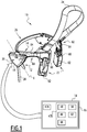
- an acoustic apparatus 10 comprises a first microphone 12, also called the first air microphone, capable of receiving acoustic sound waves and transforming them into a first electrical signal E1, and a second microphone 14, also called an osteophonic microphone, capable of receiving by bone conduction of vibratory oscillations and transform them into a second electrical signal E2.
- the acoustic apparatus 10 comprises a processing unit 16 disposed inside a protective casing 18, the processing unit 16 being able to deliver a corrected electrical signal Sc in particular as a function of the first electrical signal E1 and the second electrical signal E2.
- the acoustic apparatus 10 comprises a noise reduction device 20, the noise reduction device 20 being connected at the output of the first microphone 12 to reduce the noise in the first signal E1, and the processing unit 16 is then connected, on the one hand, at the output of the noise reduction device 20, and on the other hand, at the output of the second microphone 14.
- the acoustic apparatus 10 also comprises two lateral acoustic modules 22, an upper arch 24, a rear arch 26 connecting the acoustic modules and a connection cable 28, the connection cable being equipped at its end with a connector, not shown. .
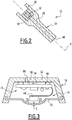
- the first microphone 12 visible on the figure 2 , comprises a main electroacoustic transducer 32 adapted to receive acoustic sound waves of a sound signal from the vocal cords and transforming said acoustic waves into the first electrical signal E1.
- the first microphone 12 has a protrusion 34, for example integral with the protective housing 18 and extending in a longitudinal direction X.
- the protrusion 34 comprises a cavity 36 for receiving the main electroacoustic transducer and a cylindrical duct 38 s extending longitudinally between the cavity 36 and a free end 40 of the protuberance, the free end 40 being located opposite the protective housing 18.
- the longitudinal direction X is oriented substantially towards the mouth of the the user when the acoustic device 10 is positioned on the head of the user.
- the longitudinal direction X forms, for example, an angle between 45 ° and 75 °, preferably equal to 60 °, with a horizontal plane in which the rear arch 26 is arranged when it is positioned against the skull of the user.
- the first microphone 12 additionally comprises an element 42 for holding the main electroacoustic transducer inside the cavity 36.
- the holding element 42 is able to dampen any mechanical vibrations of the main electroacoustic transducer 32, and is produced, for example, rubber or silicone.
- the second microphone 14 comprises a bone mechanical excitation transducer 44, visible on the figure 3 disposed in the protective housing 18, and adapted to receive by bone conduction, in particular through a corresponding bone of the skull, the vibratory waves of the sound signal from the vocal cords of the user and to transform it into the second electrical signal E2 .
- the second microphone 14 is electrically connected to the processing unit 16.
- the processing unit 16 is, for example, embodied as an electronic circuit 46, as shown in FIG. figure 3 .
- the electronic circuit 46 comprises, for example, a processor 47A and a memory 47B associated with the processor.
- the processing unit 16 comprises means 48 for calculating a corrected electrical signal Sc as a function of the first electrical signal E1 and the second electrical signal E2, the corrected electrical signal Sc being able to be delivered at the output of the acoustic device 10, possibly after being amplified by an amplifier 49.
- the calculation means 48 are, for example, made in the form of a calculation software capable of being stored in the memory 47B of the processing unit.
- the processing unit 16 additionally comprises the amplifier 49 adapted to amplify the corrected signal Sc and deliver an amplified signal S. at the output of the acoustic device 10.
- the housing 18 has a wall 50 for bearing on an area of the skull and an outer protective shell 52, the protective shell 52 for protecting both the treatment unit and the bone mechanical excitation transducer of the second microphone, and being located on the opposite side to the bearing wall 50, as shown in FIG. figure 3 .
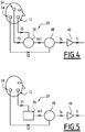
- the noise reduction device 20 is connected at the output of the main electroacoustic transducer 32 to reduce the noise in the first signal E1.
- the noise reduction device 20 comprises a third microphone 54 and first means 56 of determining a first corrected intermediate signal Int1.
- the third microphone 54 also called second air microphone, comprises a secondary electroacoustic transducer 58 adapted to receive acoustic sound waves of ambient noise and to transform said acoustic waves into a third electrical signal E3.
- the third microphone 54 is omnidirectional for capturing acoustic waves coming from several directions.
- the first determination means 56 are for example made in the form of a first determination software able to be stored in the memory 47B of the processing unit.
- the first corrected intermediate signal Int1 is a function of the first electrical signal E1 and the third electrical signal E3, the corrected electrical signal Sc then being a function of the first corrected intermediate signal Int1 and the second signal E2.
- a filter is used in order to phase the signals E1 and E3 before subtracting the signal E3 from the signal E1 according to equation (1).
- a filter is used to phase the signals E1, E2 and E3 before subtracting the signals E2 and E3 signal E1 according to equation (2).
- Each acoustic module 22, visible on the figure 1 comprises a support plate 60 on a skull lateral flank and a bone mechanical excitation transducer 62.
- Each plate 60 comprises a support plate 64 adapted to bear on the skull above an ear, the support plate 64 having a clearance passage of the ear in its lower part.
- the protective housing 18 is, for example, fixed in the rear part of the support plate 64 which is intended to be positioned above the right ear.
- the support plates 64 are made of plastic material and injection molded.
- Each acoustic module 22 comprises a hinge 66 provided between the support plate 60 and the transducer 62.
- a spring equips the articulation 66 and is adapted to provide a return rotation, around the hinge 66, the transducer 62 relative to the plate 60 to a rest position.
- the upper arch 24, also called headband, is of adjustable length and adapted to be positioned on the top of the head.
- the upper arch 24 is shaped like a strap of adjustable length.
- the rear arch 26 made of a rigid material, is a mechanical holding bar of the osteophonic microphone 14 and each acoustic module 22 resting on a corresponding lateral side of the skull.
- the holding bar 26 is of adjustable length, and able to be positioned under the bone of the rock behind the head, near the nape of the neck.
- the bone mechanical excitation transducer 44 is an accelerometer, preferably a one-axis accelerometer, oriented substantially in a direction normal to the bearing wall 50, in order to allow a homogeneous reproduction of the vibratory wave transmitted by bone conduction. according to the different users.
- the bone mechanical excitation transducer 44 is oriented towards the inside, that is to say towards the skull of the user when the acoustic apparatus 10 is positioned on the skull.
- the calculation means 48 are connected, on the one hand, at the output of the noise reduction device 20, and on the other hand, at the output of the bone mechanical excitation transducer 44.
- the wall 50 is in the form of a skin in contact with the accelerometer 44 of the second microphone.
- the skin 50 visible in section on the figure 3 has a value hardness of between 45 and 85 A shores, so that the skin 50 is of mechanical impedance substantially equal to the mechanical impedance of the corresponding area of the skull.
- the value of the hardness of the skin 50 is preferably between 55 and 80 Shore A, more preferably between 65 and 75 Shore A.
- the thickness E of the skin 50 is between 0.4 mm and 0.6 mm. mm, preferably equal to 0.5 mm.
- the skin 50 is made of synthetic rubber, for example rubber based on polychloroprene.
- the outer shell 52 has a U-shaped cross section, and is made of plastic.
- the secondary electroacoustic transducer 58 is fixed inside the outer shell 52 of the protective casing, and is adapted to receive the acoustic waves of ambient noise via an orifice 68 formed through said outer shell 52, as shown in FIG. figure 3 .
- the secondary electroacoustic transducer 58 is oriented substantially in the same direction as the bone mechanical excitation transducer 44, but in the opposite direction. In other words, the secondary electroacoustic transducer 58 is oriented substantially in a direction normal to the support wall 50 and outwardly, that is to say in the opposite direction to the skull of the user when the acoustic device 10 is positioned on the skull.
- each acoustic module 22 comprises an emissive element, not shown, able to transform an electrical signal received into vibratory waves representative of the sound signal and to transmit them to the auditory nerve by bone conduction.
- a user of the acoustic apparatus 10 begins by positioning the apparatus 10 on his head, by placing the strap 24 on top of his skull, the rear arch 26 behind his head, near his neck and the turntables. 60 support on the lateral flanks of his skull, above each respective ear. The clearance formed in the lower part of the support plates 64 ensures good ergonomics of the plate 60 relative to the upper part of the flag of the ear.
- each bone mechanical excitation transducer 62 on the corresponding temple takes place naturally and automatically by each articulation 66.
- the first microphone 12 picks up a sound signal comprising both a component corresponding to the voice of the user, a component corresponding to the ambient noise, and than an osteophonic component.
- the second microphone 14, also called osteophonic microphone captures only the osteophonic component of the sound signal, and the third microphone 54 essentially captures, by its orientation, the component corresponding to the ambient noise.
- the corrected electrical signal Sc thus essentially contains the only component corresponding to the voice of the user, since the subtraction of the third electrical signal E3 makes it possible to eliminate the component corresponding to the ambient noise , then that the subtraction of the second electrical signal E2 makes it possible to eliminate the osteophonic component of the sound signal.
- the component corresponding to the ambient noise is eliminated from the signal delivered at the output of the acoustic apparatus 10, whereas with the acoustic apparatus of the state of the art this component corresponding to ambient noise is not attenuated.
- the acoustic device 10 can further reduce the noise in the electrical signal corresponding to the voice of the user, to improve the quality of the signal delivered by the acoustic device.
- FIG 5 illustrates a first variant of this first embodiment for which elements similar to those described above, are identified by identical references, and are not described again.
- the noise reduction device 20 comprises means 70 for digital noise processing, and does not include the third microphone or the first determination means.
- the digital noise processing means 70 are adapted to receive the first electrical signal E1 and to output the first corrected intermediate signal Int1, the first corrected intermediate signal Int1 then having a signal-to-noise ratio higher than the signal-to-noise ratio of the first signal E1.
- the digital noise processing means 70 are for example made in the form of digital noise processing software capable of being stored in the memory 47B of the processing unit.
- the digital noise processing means 70 are suitable for implementing a noise reduction algorithm based on Wiener filtering and on extended spectral subtraction.
- the digital processing means 70 comprise an input 70A, an output 70B, a Wiener filter 71 connected to the input 70A, and an adder 72 connected to the output of the Wiener filter 71 via a first amplifier 73.
- the digital processing means 70 comprise a first inverter 74 connected at the output of the adder 72 and a second amplifier 75 connecting the output of the first inverter 74 to the adder 72.
- the digital processing means 70 comprise a first adder 76 connected to the input 70A and at the output of the adder 72, and a second inverter 77 connected between the output of the first adder 76 and the Wiener filter 71.
- the digital processing means 70 comprise a second adder 78 connected to the input 70A and at the output of the filter of Wiener 71 via a third amplifier 79, the output of the second summator 78 being connected to the output 70B of the digital processing means 70.
- the digital processing means 70 are adapted to receive at the input 70A at time p the module of a noise-containing speech signal, the noisy speech signal at the instant p being denoted by X p .
- the Wiener filter 71 has a transfer function H p and is capable of outputting the noise spectrum module estimated at the instant p, the noise spectrum estimated at the instant p being denoted by N p .
- the first amplifier 73 has a gain equal to 1- ⁇
- the second amplifier 75 has a gain equal to ⁇ , where ⁇ is a coefficient between 0 and 1.
- the first inverter 74 makes it possible to obtain at the output the noise spectrum module estimated at the previous instant p-1
- the signal delivered at the output of the first adder 76 corresponds to the modulus of an average of the estimates of the speech at the instant p, the average of the estimates of the speech at the instant p being noted S p and checking the following equation:
- the second inverter 77 makes it possible to obtain at the output the modulus of the average of the estimates of the speech at the previous instant p-1
- the third amplifier 79 has a gain equal to K, and the signal delivered at the output of the second summer 78 corresponds to the modulus of the estimated speech signal at the instant p, the estimated speech signal at the instant p being noted ⁇ p and checking the following equation:
- is delivered at the output 70B of the digital noise processing means 70, and corresponds to the first corrected intermediate signal Int1 which has a signal-to-noise ratio higher than the signal-to-noise ratio of the first signal E1 received at the input of the digital noise processing means 70.
- the corrected electrical signal Sc is equal to the subtraction of the second signal E2 to the first corrected intermediate signal Int1, and then verifies the equation (2) described above.
- the corrected electrical signal Sc therefore essentially contains the only component corresponding to the voice of the user, since the digital noise processing makes it possible to greatly reduce the component corresponding to the ambient noise. , then that the subtraction of the second electrical signal E2 makes it possible to eliminate the osteophonic component of the sound signal.
- the component corresponding to the ambient noise is greatly reduced in the signal delivered at the output of the acoustic apparatus 10, whereas with the acoustic apparatus of the state of the technical this component corresponding to the ambient noise is not attenuated.
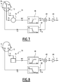
- FIG 7 illustrates a second variant of this first embodiment for which elements similar to those described above, are identified by identical references, and are not described again.
- the noise reduction device 20 comprises the third microphone 54 and the first determination means 56.
- the noise reduction device 20 does not include digital noise processing means.
- the acoustic apparatus 10 further comprises first filtering means 80 connected between the noise reduction device 20 and the calculation means 48, the first filtering means 80 being able to reduce the amplitude. signal for frequencies lower than a first predetermined frequency F1.
- the first filtering means 80 form a high-pass filter with a cut-off frequency equal to the first predetermined frequency F1.
- the first filtering means 80 are for example made in the form of a first filtering software capable of being stored in the memory 47B of the processing unit.
- the first predetermined frequency F1 has a value, for example between 800 Hz and 1600 Hz, preferably substantially equal to 1200 Hz.
- the acoustic apparatus 10 comprises second filtering means 82 connected between the bone mechanical excitation transducer of the second microphone 14 and the calculating means 48, the second filtering means 82 being able to reduce the amplitude of the signal for frequencies higher than a second predetermined frequency F2.
- the second filtering means 82 form a low-pass filter with a cut-off frequency equal to the second predetermined frequency F2.
- the second filtering means 82 are for example made in the form of a second filtering software capable of being stored in the memory 47B of the processing unit.
- the second predetermined frequency F2 presents a value, for example between 400 Hz and 1200 Hz, preferably substantially equal to 800 Hz.
- a filter is used to phase the signals E1, E2 and E3 before subtracting the high frequency part of the signal E3 from the high frequency part of the signal E1, and then adding the result of this subtraction from the low frequency part of the signal E2 according to equation (8).
- the corrected electrical signal Sc thus essentially contains the high frequency portion of the component corresponding to the voice of the user and the low frequency portion of the osteophonic component of the signal.
- the signal from the first filtering means 80 comprises a reduced osteophonic component, since the osteophonic component of the sound signal lies mainly in the low frequency domain.
- the quality of the signal delivered by the acoustic apparatus 10 according to the invention is further improved since the low frequency part of the osteophonic component offers a better intelligibility of the sound signal coming from the vocal cords than the low frequency part. the component corresponding to the voice, especially in case of whispering of the user.
- the low end Frequencies of the osteophonic component is substantially identical to the low frequency part of the component corresponding to the voice.
- the component corresponding to the ambient noise is eliminated from the signal delivered at the output of the acoustic apparatus 10, while offering a better restitution of the signal in the event of a whispering of the sound. 'user.
- FIG 8 illustrates a third variant of this first embodiment for which elements similar to those described above, are identified by identical references, and are not described again.
- the noise reduction device 20 comprises the digital noise processing means 70, and has neither the third microphone nor the first determination means.
- the acoustic apparatus 10 furthermore comprises the first filtering means 80 connected between the noise reduction device 20 and the calculation means 48.
- the acoustic device 10 comprises the second filtering means 82 connected between the bone mechanical excitation transducer of the second microphone 14 and the calculation means 48.
- the corrected electrical signal Sc is then equal to the addition of the low frequency part of the second signal E2 and the high frequency part of the first corrected intermediate signal Int1, and then verifies the equation (7) described above.
- the corrected electrical signal Sc therefore essentially contains the high frequency part of the component corresponding to the voice of the user and the low frequency part of the osteophonic component of the sound signal, since the digital noise processing makes it possible to strongly reduce the component corresponding to the ambient noise in the first signal E1.
- FIG 9 illustrates a fourth variant of this first embodiment for which elements similar to those described above, are identified by identical references, and are not described again.
- the noise reduction device 20 comprises the third microphone 54 and the first determination means 56.
- the noise reduction device 20 does not include digital noise processing means.
- the acoustic apparatus 10 comprises the first filtering means 80 connected between the noise reduction device 20 and the calculation means 48.
- the acoustic apparatus 10 comprises the second filtering means 82 connected between the mechanical excitation transducer. bone of the second microphone 14 and the calculation means 48.
- the noise reduction device 20 further comprises second means 90 for determining a second corrected intermediate signal Int2 as a function of the first corrected intermediate signal Int1 and the second signal E2, the second determination means 90 being connected at the output of the first determination means 56.
- the second determination means 90 are, for example, made in the form of a second determination software that can be stored in the memory 47B of the processing unit.
- a filter is used to phase the signals E1, E2 and E3 before subtracting the signals E2 and E3 to the signal E1 according to equation (12).
- the second corrected intermediate signal Int2 thus essentially contains the only component corresponding to the voice of the user, since the subtraction of the third electrical signal E3 makes it possible to eliminate the component corresponding to the noise ambient, and that the subtraction of the second electrical signal E2 eliminates the osteophonic component of the sound signal.
- a filter is used to phase the signals E1, E2 and E3 before subtracting the high part frequencies of the signals E2 and E3 at the high frequency portion of the signal E1, and then add the result of this subtraction to the low frequency part of the signal E2 according to equation (11).
- the corrected electrical signal Sc therefore contains only the high frequency portion of the component corresponding to the user's voice and the low frequency portion of the osteophonic component of the signal.
- the subtraction of the third electrical signal E3 makes it possible to eliminate the component corresponding to the ambient noise from the first signal E1
- the subtraction of the second electrical signal E2 makes it possible to eliminate the osteophonic component of the sound signal from the first signal E1; .
- the quality of the signal delivered by the acoustic apparatus 10 according to the invention is further improved since the high frequency part of the delivered signal comprises only the component corresponding to the voice of the user.
- the component corresponding to the ambient noise is eliminated from the signal delivered at the output of the acoustic apparatus 10, while offering a better restitution of the signal in case of whispering of the sound. user and better intelligibility of the signal delivered in high frequencies.
- FIG 10 illustrates a fifth variant of this first embodiment for which elements similar to those described above, are identified by identical references, and are not described again.
- the noise reduction device 20 comprises the digital noise processing means 70, and does not include either the third microphone or the first determination means.
- the acoustic apparatus 10 comprises the first filtering means 80 connected between the noise reduction device 20 and the calculation means 48.
- the acoustic apparatus 10 comprises the second filtering means 82 connected between the mechanical excitation transducer. bone of the second microphone 14 and the calculation means 48.
- the noise reduction device 20 further comprises the second means 90 for determining a second corrected intermediate signal Int2 as a function of the first corrected intermediate signal Int1 and the second signal E2, the second determination means 90 being connected at the output of the digital noise processing means 70.
- the corrected electrical signal Sc is then equal to the addition of the low frequency part of the second signal E2 and the high frequency part of the second corrected intermediate signal Int2, and then verifies the equation (13) described above.
- the corrected electrical signal Sc therefore contains the high frequency part of the component corresponding to the voice of the user and the low frequency part of the osteophonic component of the sound signal, being Since the digital noise processing makes it possible to strongly reduce the component corresponding to the ambient noise in the first signal E1 and the subtraction of the second electrical signal E2 makes it possible to eliminate the osteophonic component of the sound signal from the first signal E1.
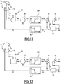
- FIG 11 illustrates a sixth variant of this first embodiment for which elements similar to those described above, are identified by identical references, and are not described again.
- the acoustic apparatus 10 further comprises switching means 95 able to switch between a first configuration in which the electrical signal S adapted to be delivered at the output of the acoustic apparatus 10 is a function of the electrical signal corrected Sc from the calculation means and a second configuration in which the electrical signal S adapted to be delivered at the output of the acoustic device 10 is only a function of the second electrical signal E2.
- the switching means 95 are, for example, connected at the output, on the one hand, calculating means 48, and secondly, second filtering means 82, as shown in FIG. figure 11 .
- the switching means 95 are controllable means according to a control law, and the control law depends on a first signal-to-noise ratio SNR 1 which is a function of the first electrical signal E1 and the second electrical signal E2.
- the estimated energies In 1 and In 2 are calculated according to an average, such as an arithmetic average, of the values of the first E1, and respectively second E2, electrical signals during a given time period.
- the control law is such that the switching means 95 switch in the first configuration when the first signal-to-noise ratio SNR 1 has a value greater than a first threshold.
- the first threshold is for example equal to 15 dB.
- control law also depends on a second signal to noise ratio SNR 2 which is a function of the first corrected intermediate signal Int1 and the second electrical signal E2.
- the control law is then such that the switching means 95 also switch in the first configuration when the first signal to noise ratio SNR 1 has a value less than or equal to the first threshold and the difference ⁇ has a value greater than a second threshold.
- the second threshold is for example equal to 5 dB.
- the law of control is such that the switching means 95 switch in the second configuration.
- the electrical signal S is then only dependent on the second electrical signal E2.
- the figure 12 illustrates a sixth variant of this first embodiment for which elements similar to those of the fifth variant which have been described above, are identified by identical references, and are not described again.
- the noise reduction device 20 comprises the digital noise processing means 70 in place of the third microphone and the first means for determining the fifth variant.
- FIG 13 illustrates a second embodiment for which elements similar to those of the first embodiment described above, are identified by identical references, and are not described again.
- the second microphone 14 is not disposed in the protective housing 18, but is arranged in an additional box 100, the additional box 100 being connected to one of the two acoustic modules 22 by two arms The bone mechanical excitation transducer 44 of the second microphone is then disposed in the additional housing 100.
- the additional box 100 is preferably intended to be applied in contact with the right side of the skull of the user, and the additional box 100 is then preferably connected to the acoustic module 22 right.
- the second microphone 14 is then identical to the contact microphone described in the document FR 2 945 905 A1 .
- the arrangement of the second microphone 14 inside the additional box 100 is similar to the arrangement of the contact microphone in its protective case as described in the document FR 2 945 905 A1 .
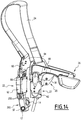
- the figure 14 illustrates a third embodiment for which elements similar to those of the first embodiment described above, are identified by identical references, and are not described again.
- the first microphone 12 and the second microphone 14 are not arranged in the protective case 18, but are arranged in an additional box 200, the additional box 200 being connected to one of the two acoustic modules 22 by two connecting arms 202.
- the main electroacoustic transducer 32 and the bone mechanical excitation transducer 44 are then each disposed in the additional housing 200.
- the additional box 200 is preferably intended to be applied in contact with the right side of the user's skull, and the additional box 200 is then preferably connected to the right acoustic module 22, as shown in FIG. figure 14 .
- the second microphone 14 is identical to the contact microphone described in the document FR 2 945 905 A1 .
- the arrangement of the second microphone 14 inside the additional box 200 is analogous to the arrangement of the contact microphone in its protective case as described in the document FR 2 945 905 A1 .
- the upper arch 24 for example in the form of a strap, allows, because of its small thickness and its flexible material, the port a heavy helmet without discomfort on the top of the head.
- the mechanical support of the second microphone 14 and the two modules 22 in contact with the skull is provided by the rear bow 26, while the upper bow 24 has a holding role in position on the top of the head.
- the acoustic device 10 is also suitable for use with a biker helmet, a helmet for a motor vehicle driver, a helmet for an armored vehicle, a fireman's helmet, a helmet for a security guard, a construction helmet, or even a helmet for an aircraft pilot.
- the acoustic device 10 is a headphone for operator.
- the acoustic device 10 can further reduce the noise in the electrical signal corresponding to the voice of the user, in order to improve the quality of the signal delivered.
Landscapes
- Engineering & Computer Science (AREA)
- Physics & Mathematics (AREA)
- Acoustics & Sound (AREA)
- Signal Processing (AREA)
- Health & Medical Sciences (AREA)
- General Health & Medical Sciences (AREA)
- Otolaryngology (AREA)
- Multimedia (AREA)
- Circuit For Audible Band Transducer (AREA)
Claims (8)
- Akustische Vorrichtung (10), aufweisend:- ein erstes Mikrofon (12), wobei das erste Mikrofon (12) einen elektroakustischen Hauptwandler (32) aufweist, der in der Lage ist, akustische Schallwellen eines Schallsignals zu empfangen, das aus den Stimmbändern stammt, und die akustischen Wellen in ein erstes elektrisches Signal (E1) umzuwandeln,- ein zweites Mikrofon (14), wobei das zweite Mikrofon (14) einen Wandler mit mechanischer Knochenanregung (44) aufweist, der in der Lage ist, durch Knochenleitung Vibrationsschwingungen des Schallsignals zu empfangen und die Vibrationsschwingungen in ein zweites elektrisches Signal (E2) umzuwandeln,- Mittel (48) zum Berechnen eines korrigierten elektrischen Signals (Sc) in Abhängigkeit von dem ersten elektrischen Signal (E1) und dem zweiten elektrischen Signal (E2), wobei das korrigierte elektrische Signal (Sc) in der Lage ist, am Ausgang der akustischen Vorrichtung (10) ausgegeben zu werden,- eine Vorrichtung zur Rauschminderung (20), wobei die Vorrichtung zur Rauschminderung (20) am Ausgang des elektroakustischen Hauptwandlers (32) angeschlossen ist, um das Rauschen in dem ersten elektrischen Signal (E1) zu verringern, und die Mittel zum Berechnen (48) einerseits am Ausgang der Vorrichtung zur Rauschminderung (20) und andererseits am Ausgang des Wandlers mit mechanischer Knochenanregung (44) angeschlossen sind,wobei die Vorrichtung zur Rauschminderung (20) ein drittes Mikrofon (54) und erste Mittel (56) zum Ermitteln eines ersten korrigierten Zwischensignals (Int1) aufweist, wobei das dritte Mikrofon (54) einen sekundären elektroakustischen Wandler (58) aufweist, der in der Lage ist, akustische Schallwellen eines Umgebungsgeräuschs zu empfangen und die akustischen Wellen in ein drittes elektrisches Signal (E3) umzuwandeln, wobei das erste korrigierte Zwischensignal (Int1) von dem ersten elektrischen Signal (E1) und dem dritten elektrischen Signal (E3) abhängig ist,
wobei das erste korrigierte Zwischensignal (Int1) die folgende Gleichung verifiziert:
E3 das dritte elektrische Signal repräsentiert,
wobei die Vorrichtung zur Rauschminderung (20) Mittel zum Ermitteln eines zweiten korrigierten Zwischensignals (Int2) in Abhängigkeit von dem ersten korrigierten Zwischensignal (Int1) und dem zweiten Signal (E2) aufweist, wobei die Mittel zum Ermitteln am Ausgang der ersten Mittel zum Ermitteln (56) angeschlossen sind und das korrigierte elektrische Signal (Sc) dann von dem zweiten korrigierten Zwischensignal (Int2) abhängt,
dadurch gekennzeichnet, dass das zweite korrigierte Zwischensignal (Int2) die folgende Gleichung verifiziert:
E2 das zweite elektrische Signal repräsentiert. - Akustische Vorrichtung (10), aufweisend:- ein erstes Mikrofon (12), wobei das erste Mikrofon (12) einen elektroakustischen Hauptwandler (32) aufweist, der in der Lage ist, akustische Schallwellen eines Schallsignals zu empfangen, das aus den Stimmbändern stammt, und die akustischen Wellen in ein erstes elektrisches Signal (E1) umzuwandeln,- ein zweites Mikrofon (14), wobei das zweite Mikrofon (14) einen Wandler mit mechanischer Knochenanregung (44) aufweist, der in der Lage ist, durch Knochenleitung Vibrationsschwingungen des Schallsignals zu empfangen und die Vibrationsschwingungen in ein zweites elektrisches Signal (E2) umzuwandeln,- Mittel (48) zum Berechnen eines korrigierten elektrischen Signals (Sc) in Abhängigkeit von dem ersten elektrischen Signal (E1) und dem zweiten elektrischen Signal (E2), wobei das korrigierte elektrische Signal (Sc) in der Lage ist, am Ausgang der akustischen Vorrichtung (10) ausgegeben zu werden,- eine Vorrichtung zur Rauschminderung (20), wobei die Vorrichtung zur Rauschminderung (20) am Ausgang des elektroakustischen Hauptwandlers (32) angeschlossen ist, um das Rauschen in dem ersten elektrischen Signal (E1) zu verringern, und die Mittel zum Berechnen (48) einerseits am Ausgang der Vorrichtung zur Rauschminderung (20) und andererseits am Ausgang des Wandlers mit mechanischer Knochenanregung (44) angeschlossen sind,wobei die Vorrichtung zur Rauschminderung (20) Mittel zur digitalen Verarbeitung des Rauschens (70) aufweist, die in der Lage sind, das erste elektrische Signal (E1) zu empfangen und ein erstes korrigiertes Zwischensignal (Int1) auszugeben, wobei das erste korrigierte Zwischensignal (Int1) ein Signal-Rausch-Verhältnis aufweist, das größer als das Signal-Rausch-Verhältnis des ersten Signals (E1) ist,
wobei die Vorrichtung zur Rauschminderung (20) Mittel zum Ermitteln eines zweiten korrigierten Zwischensignals (Int2) in Abhängigkeit von dem ersten korrigierten Zwischensignal (Int1) und dem zweiten Signal (E2) aufweist, wobei die Mittel zum Ermitteln am Ausgang der Mittel zur digitalen Verarbeitung des Rauschens (70) angeschlossen sind und das korrigierte elektrische Signal (Sc) dann von dem zweiten korrigierten Zwischensignal (Int2) abhängt,
dadurch gekennzeichnet, dass das zweite korrigierte Zwischensignal (Int2) die folgende Gleichung verifiziert:
E2 das zweite elektrische Signal repräsentiert. - Akustische Vorrichtung (10) gemäß irgendeinem der vorhergehenden Ansprüche, wobei die akustische Vorrichtung (10) ferner erste Filtermittel (80) aufweist, die zwischen der Vorrichtung zur Rauschminderung (20) und den Mitteln zum Berechnen (48) angeschlossen sind, wobei die ersten Filtermittel (80) in der Lage sind, die Amplitude des Signals für Frequenzen zu verringern, die kleiner als eine erste vorbestimmte Frequenz (F1) sind.
- Akustische Vorrichtung (10) gemäß irgendeinem der vorhergehenden Ansprüche, wobei die akustische Vorrichtung (10) ferner zweite Filtermittel (82) aufweist, die zwischen dem Wandler mit mechanischer Knochenanregung (44) und den Mitteln zum Berechnen (48) angeschlossen sind, wobei die zweiten Filtermittel (82) in der Lage sind, die Amplitude des Signals für Frequenzen zu verringern, die größer als eine zweite vorbestimmte Frequenz (F2) sind.
- Akustische Vorrichtung (10) gemäß irgendeinem der vorhergehenden Ansprüche, wobei die akustische Vorrichtung (10) ferner Mittel zum Umschalten (95) aufweist, die in der Lage sind, zwischen einer ersten Konfiguration, in der das elektrische Signal (S), das in der Lage ist, am Ausgang der akustischen Vorrichtung (10) ausgegeben zu werden, abhängig von dem korrigierten elektrischen Signal (Sc) ist, das aus den Mitteln zum Berechnen stammt, und einer zweiten Konfiguration umzuschalten, in der das elektrische Signal (S), das in der Lage ist, am Ausgang der akustischen Vorrichtung (10) ausgegeben zu werden, ausschließlich von dem zweiten elektrischen Signal (E2) abhängt.
- Akustische Vorrichtung (10) gemäß Anspruch 5, wobei die Mittel zum Umschalten (95) Mittel sind, die gemäß einem Steuergesetz steuerbar sind, und das Steuergesetz von einem Signal-Rausch-Verhältnis abhängt, das von dem ersten elektrischen Signal (E1) und dem zweiten elektrischen Signal (E2) abhängt.
- Akustische Vorrichtung (10) gemäß irgendeinem der vorhergehenden Ansprüche, wobei die akustische Vorrichtung (10) ferner zwei seitliche akustische Module (22) aufweist, die an den seitlichen Flanken des Schädels abgestützt sind und in der Lage sind, dem Hörnerv ein Schallsignal zu übermitteln.
- Kopfeinrichtung für Bedienperson, aufweisend einen Schutzhelm, dadurch gekennzeichnet dass sie eine akustische Vorrichtung (10) gemäß irgendeinem der vorhergehenden Ansprüche aufweist.
Applications Claiming Priority (2)
| Application Number | Priority Date | Filing Date | Title |
|---|---|---|---|
| FR1452506A FR3019422B1 (fr) | 2014-03-25 | 2014-03-25 | Appareil acoustique comprenant au moins un microphone electroacoustique, un microphone osteophonique et des moyens de calcul d'un signal corrige, et equipement de tete associe |
| PCT/EP2015/056261 WO2015144708A1 (fr) | 2014-03-25 | 2015-03-24 | Appareil acoustique comprenant au moins un microphone électroacoustique, un microphone ostéophonique et des moyens de calcul d'un signal corrigé, et équipement de tête associé |
Publications (2)
| Publication Number | Publication Date |
|---|---|
| EP3123740A1 EP3123740A1 (de) | 2017-02-01 |
| EP3123740B1 true EP3123740B1 (de) | 2019-01-02 |
Family
ID=51210532
Family Applications (1)
| Application Number | Title | Priority Date | Filing Date |
|---|---|---|---|
| EP15711549.4A Active EP3123740B1 (de) | 2014-03-25 | 2015-03-24 | Akustische vorrichtung mit mindestens einem elektroakustischen mikrofon, einem osteofonen mikrofon und vorrichtung zur berechnung eines korrigierten signals sowie zugehörige kopfbedeckung |
Country Status (3)
| Country | Link |
|---|---|
| EP (1) | EP3123740B1 (de) |
| FR (1) | FR3019422B1 (de) |
| WO (1) | WO2015144708A1 (de) |
Families Citing this family (4)
| Publication number | Priority date | Publication date | Assignee | Title |
|---|---|---|---|---|
| CN109640234A (zh) * | 2018-10-31 | 2019-04-16 | 深圳市伊声声学科技有限公司 | 一种双骨导传声器及噪音去除实现方法 |
| FR3134939B1 (fr) | 2022-04-20 | 2025-03-14 | Elno | Appareil électronique d'interconnexion adapté pour interconnecter plusieurs équipement audio, et système audio comprenant un tel appareil |
| FR3135816A1 (fr) | 2022-05-20 | 2023-11-24 | Elno | Connecteur électrique militarisé destiné à être connecté à un équipement audio, câble de connexion et système audio associés |
| FR3136096B1 (fr) | 2022-05-30 | 2024-11-08 | Elno | Dispositif électronique et procédé de traitement, appareil acoustique et programme d’ordinateur associés |
Family Cites Families (7)
| Publication number | Priority date | Publication date | Assignee | Title |
|---|---|---|---|---|
| EP0683621B1 (de) * | 1994-05-18 | 2002-03-27 | Nippon Telegraph And Telephone Corporation | Sender-Empfänger mit einem akustischen Wandler vom Ohrpassstück-Typ |
| US5692059A (en) | 1995-02-24 | 1997-11-25 | Kruger; Frederick M. | Two active element in-the-ear microphone system |
| US7283850B2 (en) | 2004-10-12 | 2007-10-16 | Microsoft Corporation | Method and apparatus for multi-sensory speech enhancement on a mobile device |
| FR2945905B1 (fr) * | 2009-05-20 | 2011-07-29 | Elno Soc Nouvelle | Dispositif acoustique |
| US20110293109A1 (en) * | 2010-05-27 | 2011-12-01 | Sony Ericsson Mobile Communications Ab | Hands-Free Unit with Noise Tolerant Audio Sensor |
| EP2458586A1 (de) * | 2010-11-24 | 2012-05-30 | Koninklijke Philips Electronics N.V. | System und Verfahren zur Erzeugung eines Audiosignals |
| FR2974655B1 (fr) * | 2011-04-26 | 2013-12-20 | Parrot | Combine audio micro/casque comprenant des moyens de debruitage d'un signal de parole proche, notamment pour un systeme de telephonie "mains libres". |
-
2014
- 2014-03-25 FR FR1452506A patent/FR3019422B1/fr active Active
-
2015
- 2015-03-24 EP EP15711549.4A patent/EP3123740B1/de active Active
- 2015-03-24 WO PCT/EP2015/056261 patent/WO2015144708A1/fr not_active Ceased
Non-Patent Citations (1)
| Title |
|---|
| None * |
Also Published As
| Publication number | Publication date |
|---|---|
| FR3019422B1 (fr) | 2017-07-21 |
| EP3123740A1 (de) | 2017-02-01 |
| FR3019422A1 (fr) | 2015-10-02 |
| WO2015144708A1 (fr) | 2015-10-01 |
Similar Documents
| Publication | Publication Date | Title |
|---|---|---|
| EP2518724B1 (de) | Kombinierte Audioeinheit bestehend aus Mikrofon und Kopfhörer, die Mittel zur Geräuschdämpfung eines nahen Wortsignals umfasst, insbesondere für eine telefonische Freisprechanlage | |
| CA1265063A (fr) | Procedes et dispositifs pour attenuer les bruits d'origine externe parvenant au tympan et ameliorer l'intelligibilite des communications electro- acoustiques | |
| EP3828880B1 (de) | Geräuschdämpfende kopfstütze für einen fahrzeugsitz | |
| EP2530673B1 (de) | Audiogerät mit Rauschunterdrückung in einem Sprachsignal unter Verwendung von einem Filter mit fraktionaler Verzögerung | |
| US20160142815A1 (en) | Headset with end-firing microphone array and automatic calibration of end-firing array | |
| FR3019961A1 (fr) | Casque audio a controle actif de bruit anc avec reduction du souffle electrique | |
| FR3021180A1 (fr) | Casque audio a controle actif de bruit anc avec prevention des effets d'une saturation du signal microphonique "feedback" | |
| FR2572613A1 (fr) | Masque respiratoire a transducteur electro-acoustique pour la transmission de la parole | |
| FR2631815A1 (fr) | Bouchon protecteur auriculaire | |
| EP0818121B1 (de) | System zur ton- und höraufnahme für helm in geräuschvoller umgebung | |
| EP3123740A1 (de) | Akustische vorrichtung mit mindestens einem elektroakustischen mikrofon, einem osteofonen mikrofon und vorrichtung zur berechnung eines korrigierten signals sowie zugehörige kopfbedeckung | |
| FR2857551A1 (fr) | Dispositif pour capter ou reproduire des signaux audio | |
| EP4342190A1 (de) | Knochenleitungshörgerät | |
| WO2022136807A1 (fr) | Casque audio a reduction de bruit active | |
| EP3000109B1 (de) | Akustische vorrichtung mit aktiver rauschverminderung | |
| EP2433431B1 (de) | Akustische vorrichtung | |
| WO2010133812A1 (fr) | Dispositif acoustique | |
| FR3161831A1 (fr) | Dispositif d’écoute par conduction osseuse | |
| WO2007007265A1 (fr) | Dispositif auditif permettant la perception claire de signaux acoustiques dans un environnement bruyant | |
| WO2015079126A1 (fr) | Bonnet pour une tête de cheval | |
| FR2597693A1 (fr) | Capteur acoustique, notamment osteo-microphone et son utilisation conjointe avec un casque de protection. | |
| FR2819367A1 (fr) | Appareil electrique portatif comportant des moyens de restitution sonore |
Legal Events
| Date | Code | Title | Description |
|---|---|---|---|
| STAA | Information on the status of an ep patent application or granted ep patent |
Free format text: STATUS: THE INTERNATIONAL PUBLICATION HAS BEEN MADE |
|
| PUAI | Public reference made under article 153(3) epc to a published international application that has entered the european phase |
Free format text: ORIGINAL CODE: 0009012 |
|
| STAA | Information on the status of an ep patent application or granted ep patent |
Free format text: STATUS: REQUEST FOR EXAMINATION WAS MADE |
|
| 17P | Request for examination filed |
Effective date: 20161025 |
|
| AK | Designated contracting states |
Kind code of ref document: A1 Designated state(s): AL AT BE BG CH CY CZ DE DK EE ES FI FR GB GR HR HU IE IS IT LI LT LU LV MC MK MT NL NO PL PT RO RS SE SI SK SM TR |
|
| AX | Request for extension of the european patent |
Extension state: BA ME |
|
| DAV | Request for validation of the european patent (deleted) | ||
| DAX | Request for extension of the european patent (deleted) | ||
| STAA | Information on the status of an ep patent application or granted ep patent |
Free format text: STATUS: EXAMINATION IS IN PROGRESS |
|
| 17Q | First examination report despatched |
Effective date: 20180116 |
|
| GRAP | Despatch of communication of intention to grant a patent |
Free format text: ORIGINAL CODE: EPIDOSNIGR1 |
|
| STAA | Information on the status of an ep patent application or granted ep patent |
Free format text: STATUS: GRANT OF PATENT IS INTENDED |
|
| RIC1 | Information provided on ipc code assigned before grant |
Ipc: H04R 3/00 20060101AFI20180709BHEP Ipc: H04R 1/46 20060101ALI20180709BHEP Ipc: H04R 1/10 20060101ALN20180709BHEP Ipc: H04R 1/08 20060101ALI20180709BHEP |
|
| INTG | Intention to grant announced |
Effective date: 20180725 |
|
| GRAS | Grant fee paid |
Free format text: ORIGINAL CODE: EPIDOSNIGR3 |
|
| GRAA | (expected) grant |
Free format text: ORIGINAL CODE: 0009210 |
|
| STAA | Information on the status of an ep patent application or granted ep patent |
Free format text: STATUS: THE PATENT HAS BEEN GRANTED |
|
| AK | Designated contracting states |
Kind code of ref document: B1 Designated state(s): AL AT BE BG CH CY CZ DE DK EE ES FI FR GB GR HR HU IE IS IT LI LT LU LV MC MK MT NL NO PL PT RO RS SE SI SK SM TR |
|
| REG | Reference to a national code |
Ref country code: GB Ref legal event code: FG4D Free format text: NOT ENGLISH |
|
| REG | Reference to a national code |
Ref country code: CH Ref legal event code: EP Ref country code: AT Ref legal event code: REF Ref document number: 1085972 Country of ref document: AT Kind code of ref document: T Effective date: 20190115 |
|
| REG | Reference to a national code |
Ref country code: IE Ref legal event code: FG4D Free format text: LANGUAGE OF EP DOCUMENT: FRENCH |
|
| REG | Reference to a national code |
Ref country code: DE Ref legal event code: R096 Ref document number: 602015022725 Country of ref document: DE |
|
| REG | Reference to a national code |
Ref country code: CH Ref legal event code: NV Representative=s name: MICHELI AND CIE SA, CH |
|
| REG | Reference to a national code |
Ref country code: NL Ref legal event code: MP Effective date: 20190102 |
|
| REG | Reference to a national code |
Ref country code: LT Ref legal event code: MG4D |
|
| REG | Reference to a national code |
Ref country code: AT Ref legal event code: MK05 Ref document number: 1085972 Country of ref document: AT Kind code of ref document: T Effective date: 20190102 |
|
| PG25 | Lapsed in a contracting state [announced via postgrant information from national office to epo] |
Ref country code: NL Free format text: LAPSE BECAUSE OF FAILURE TO SUBMIT A TRANSLATION OF THE DESCRIPTION OR TO PAY THE FEE WITHIN THE PRESCRIBED TIME-LIMIT Effective date: 20190102 |
|
| PG25 | Lapsed in a contracting state [announced via postgrant information from national office to epo] |
Ref country code: FI Free format text: LAPSE BECAUSE OF FAILURE TO SUBMIT A TRANSLATION OF THE DESCRIPTION OR TO PAY THE FEE WITHIN THE PRESCRIBED TIME-LIMIT Effective date: 20190102 Ref country code: NO Free format text: LAPSE BECAUSE OF FAILURE TO SUBMIT A TRANSLATION OF THE DESCRIPTION OR TO PAY THE FEE WITHIN THE PRESCRIBED TIME-LIMIT Effective date: 20190402 Ref country code: ES Free format text: LAPSE BECAUSE OF FAILURE TO SUBMIT A TRANSLATION OF THE DESCRIPTION OR TO PAY THE FEE WITHIN THE PRESCRIBED TIME-LIMIT Effective date: 20190102 Ref country code: PT Free format text: LAPSE BECAUSE OF FAILURE TO SUBMIT A TRANSLATION OF THE DESCRIPTION OR TO PAY THE FEE WITHIN THE PRESCRIBED TIME-LIMIT Effective date: 20190502 Ref country code: SE Free format text: LAPSE BECAUSE OF FAILURE TO SUBMIT A TRANSLATION OF THE DESCRIPTION OR TO PAY THE FEE WITHIN THE PRESCRIBED TIME-LIMIT Effective date: 20190102 Ref country code: LT Free format text: LAPSE BECAUSE OF FAILURE TO SUBMIT A TRANSLATION OF THE DESCRIPTION OR TO PAY THE FEE WITHIN THE PRESCRIBED TIME-LIMIT Effective date: 20190102 Ref country code: PL Free format text: LAPSE BECAUSE OF FAILURE TO SUBMIT A TRANSLATION OF THE DESCRIPTION OR TO PAY THE FEE WITHIN THE PRESCRIBED TIME-LIMIT Effective date: 20190102 |
|
| PG25 | Lapsed in a contracting state [announced via postgrant information from national office to epo] |
Ref country code: LV Free format text: LAPSE BECAUSE OF FAILURE TO SUBMIT A TRANSLATION OF THE DESCRIPTION OR TO PAY THE FEE WITHIN THE PRESCRIBED TIME-LIMIT Effective date: 20190102 Ref country code: HR Free format text: LAPSE BECAUSE OF FAILURE TO SUBMIT A TRANSLATION OF THE DESCRIPTION OR TO PAY THE FEE WITHIN THE PRESCRIBED TIME-LIMIT Effective date: 20190102 Ref country code: BG Free format text: LAPSE BECAUSE OF FAILURE TO SUBMIT A TRANSLATION OF THE DESCRIPTION OR TO PAY THE FEE WITHIN THE PRESCRIBED TIME-LIMIT Effective date: 20190402 Ref country code: GR Free format text: LAPSE BECAUSE OF FAILURE TO SUBMIT A TRANSLATION OF THE DESCRIPTION OR TO PAY THE FEE WITHIN THE PRESCRIBED TIME-LIMIT Effective date: 20190403 Ref country code: IS Free format text: LAPSE BECAUSE OF FAILURE TO SUBMIT A TRANSLATION OF THE DESCRIPTION OR TO PAY THE FEE WITHIN THE PRESCRIBED TIME-LIMIT Effective date: 20190502 Ref country code: RS Free format text: LAPSE BECAUSE OF FAILURE TO SUBMIT A TRANSLATION OF THE DESCRIPTION OR TO PAY THE FEE WITHIN THE PRESCRIBED TIME-LIMIT Effective date: 20190102 |
|
| REG | Reference to a national code |
Ref country code: DE Ref legal event code: R097 Ref document number: 602015022725 Country of ref document: DE |
|
| PG25 | Lapsed in a contracting state [announced via postgrant information from national office to epo] |
Ref country code: AT Free format text: LAPSE BECAUSE OF FAILURE TO SUBMIT A TRANSLATION OF THE DESCRIPTION OR TO PAY THE FEE WITHIN THE PRESCRIBED TIME-LIMIT Effective date: 20190102 Ref country code: DK Free format text: LAPSE BECAUSE OF FAILURE TO SUBMIT A TRANSLATION OF THE DESCRIPTION OR TO PAY THE FEE WITHIN THE PRESCRIBED TIME-LIMIT Effective date: 20190102 Ref country code: EE Free format text: LAPSE BECAUSE OF FAILURE TO SUBMIT A TRANSLATION OF THE DESCRIPTION OR TO PAY THE FEE WITHIN THE PRESCRIBED TIME-LIMIT Effective date: 20190102 Ref country code: CZ Free format text: LAPSE BECAUSE OF FAILURE TO SUBMIT A TRANSLATION OF THE DESCRIPTION OR TO PAY THE FEE WITHIN THE PRESCRIBED TIME-LIMIT Effective date: 20190102 Ref country code: RO Free format text: LAPSE BECAUSE OF FAILURE TO SUBMIT A TRANSLATION OF THE DESCRIPTION OR TO PAY THE FEE WITHIN THE PRESCRIBED TIME-LIMIT Effective date: 20190102 Ref country code: IT Free format text: LAPSE BECAUSE OF FAILURE TO SUBMIT A TRANSLATION OF THE DESCRIPTION OR TO PAY THE FEE WITHIN THE PRESCRIBED TIME-LIMIT Effective date: 20190102 Ref country code: MC Free format text: LAPSE BECAUSE OF FAILURE TO SUBMIT A TRANSLATION OF THE DESCRIPTION OR TO PAY THE FEE WITHIN THE PRESCRIBED TIME-LIMIT Effective date: 20190102 Ref country code: AL Free format text: LAPSE BECAUSE OF FAILURE TO SUBMIT A TRANSLATION OF THE DESCRIPTION OR TO PAY THE FEE WITHIN THE PRESCRIBED TIME-LIMIT Effective date: 20190102 Ref country code: SK Free format text: LAPSE BECAUSE OF FAILURE TO SUBMIT A TRANSLATION OF THE DESCRIPTION OR TO PAY THE FEE WITHIN THE PRESCRIBED TIME-LIMIT Effective date: 20190102 |
|
| PLBE | No opposition filed within time limit |
Free format text: ORIGINAL CODE: 0009261 |
|
| STAA | Information on the status of an ep patent application or granted ep patent |
Free format text: STATUS: NO OPPOSITION FILED WITHIN TIME LIMIT |
|
| PG25 | Lapsed in a contracting state [announced via postgrant information from national office to epo] |
Ref country code: LU Free format text: LAPSE BECAUSE OF NON-PAYMENT OF DUE FEES Effective date: 20190324 Ref country code: SM Free format text: LAPSE BECAUSE OF FAILURE TO SUBMIT A TRANSLATION OF THE DESCRIPTION OR TO PAY THE FEE WITHIN THE PRESCRIBED TIME-LIMIT Effective date: 20190102 |
|
| 26N | No opposition filed |
Effective date: 20191003 |
|
| PG25 | Lapsed in a contracting state [announced via postgrant information from national office to epo] |
Ref country code: IE Free format text: LAPSE BECAUSE OF NON-PAYMENT OF DUE FEES Effective date: 20190324 |
|
| PG25 | Lapsed in a contracting state [announced via postgrant information from national office to epo] |
Ref country code: SI Free format text: LAPSE BECAUSE OF FAILURE TO SUBMIT A TRANSLATION OF THE DESCRIPTION OR TO PAY THE FEE WITHIN THE PRESCRIBED TIME-LIMIT Effective date: 20190102 |
|
| PG25 | Lapsed in a contracting state [announced via postgrant information from national office to epo] |
Ref country code: TR Free format text: LAPSE BECAUSE OF FAILURE TO SUBMIT A TRANSLATION OF THE DESCRIPTION OR TO PAY THE FEE WITHIN THE PRESCRIBED TIME-LIMIT Effective date: 20190102 |
|
| PG25 | Lapsed in a contracting state [announced via postgrant information from national office to epo] |
Ref country code: MT Free format text: LAPSE BECAUSE OF FAILURE TO SUBMIT A TRANSLATION OF THE DESCRIPTION OR TO PAY THE FEE WITHIN THE PRESCRIBED TIME-LIMIT Effective date: 20190102 |
|
| PG25 | Lapsed in a contracting state [announced via postgrant information from national office to epo] |
Ref country code: CY Free format text: LAPSE BECAUSE OF FAILURE TO SUBMIT A TRANSLATION OF THE DESCRIPTION OR TO PAY THE FEE WITHIN THE PRESCRIBED TIME-LIMIT Effective date: 20190102 |
|
| PG25 | Lapsed in a contracting state [announced via postgrant information from national office to epo] |
Ref country code: HU Free format text: LAPSE BECAUSE OF FAILURE TO SUBMIT A TRANSLATION OF THE DESCRIPTION OR TO PAY THE FEE WITHIN THE PRESCRIBED TIME-LIMIT; INVALID AB INITIO Effective date: 20150324 |
|
| PG25 | Lapsed in a contracting state [announced via postgrant information from national office to epo] |
Ref country code: MK Free format text: LAPSE BECAUSE OF FAILURE TO SUBMIT A TRANSLATION OF THE DESCRIPTION OR TO PAY THE FEE WITHIN THE PRESCRIBED TIME-LIMIT Effective date: 20190102 |
|
| PGFP | Annual fee paid to national office [announced via postgrant information from national office to epo] |
Ref country code: CH Payment date: 20250401 Year of fee payment: 11 |
|
| REG | Reference to a national code |
Ref country code: CH Ref legal event code: U11 Free format text: ST27 STATUS EVENT CODE: U-0-0-U10-U11 (AS PROVIDED BY THE NATIONAL OFFICE) Effective date: 20260401 |
|
| PGFP | Annual fee paid to national office [announced via postgrant information from national office to epo] |
Ref country code: GB Payment date: 20260323 Year of fee payment: 12 |
|
| PGFP | Annual fee paid to national office [announced via postgrant information from national office to epo] |
Ref country code: DE Payment date: 20260313 Year of fee payment: 12 |
|
| PGFP | Annual fee paid to national office [announced via postgrant information from national office to epo] |
Ref country code: BE Payment date: 20260324 Year of fee payment: 12 |
|
| PGFP | Annual fee paid to national office [announced via postgrant information from national office to epo] |
Ref country code: FR Payment date: 20260212 Year of fee payment: 12 |