EP3123626B1 - Method of performing a hybrid beamforming in a wireless communication system and apparatus therefor - Google Patents
Method of performing a hybrid beamforming in a wireless communication system and apparatus therefor Download PDFInfo
- Publication number
- EP3123626B1 EP3123626B1 EP15769817.6A EP15769817A EP3123626B1 EP 3123626 B1 EP3123626 B1 EP 3123626B1 EP 15769817 A EP15769817 A EP 15769817A EP 3123626 B1 EP3123626 B1 EP 3123626B1
- Authority
- EP
- European Patent Office
- Prior art keywords
- beamforming
- analog
- effective range
- pmi
- digital
- Prior art date
- Legal status (The legal status is an assumption and is not a legal conclusion. Google has not performed a legal analysis and makes no representation as to the accuracy of the status listed.)
- Active
Links
Images


Classifications
-
- H—ELECTRICITY
- H04—ELECTRIC COMMUNICATION TECHNIQUE
- H04B—TRANSMISSION
- H04B7/00—Radio transmission systems, i.e. using radiation field
- H04B7/02—Diversity systems; Multi-antenna system, i.e. transmission or reception using multiple antennas
- H04B7/04—Diversity systems; Multi-antenna system, i.e. transmission or reception using multiple antennas using two or more spaced independent antennas
- H04B7/06—Diversity systems; Multi-antenna system, i.e. transmission or reception using multiple antennas using two or more spaced independent antennas at the transmitting station
- H04B7/0613—Diversity systems; Multi-antenna system, i.e. transmission or reception using multiple antennas using two or more spaced independent antennas at the transmitting station using simultaneous transmission
- H04B7/0615—Diversity systems; Multi-antenna system, i.e. transmission or reception using multiple antennas using two or more spaced independent antennas at the transmitting station using simultaneous transmission of weighted versions of same signal
- H04B7/0617—Diversity systems; Multi-antenna system, i.e. transmission or reception using multiple antennas using two or more spaced independent antennas at the transmitting station using simultaneous transmission of weighted versions of same signal for beam forming
-
- H—ELECTRICITY
- H04—ELECTRIC COMMUNICATION TECHNIQUE
- H04B—TRANSMISSION
- H04B7/00—Radio transmission systems, i.e. using radiation field
- H04B7/02—Diversity systems; Multi-antenna system, i.e. transmission or reception using multiple antennas
- H04B7/04—Diversity systems; Multi-antenna system, i.e. transmission or reception using multiple antennas using two or more spaced independent antennas
- H04B7/0413—MIMO systems
- H04B7/0456—Selection of precoding matrices or codebooks, e.g. using matrices antenna weighting
-
- H—ELECTRICITY
- H04—ELECTRIC COMMUNICATION TECHNIQUE
- H04B—TRANSMISSION
- H04B7/00—Radio transmission systems, i.e. using radiation field
- H04B7/02—Diversity systems; Multi-antenna system, i.e. transmission or reception using multiple antennas
- H04B7/04—Diversity systems; Multi-antenna system, i.e. transmission or reception using multiple antennas using two or more spaced independent antennas
- H04B7/06—Diversity systems; Multi-antenna system, i.e. transmission or reception using multiple antennas using two or more spaced independent antennas at the transmitting station
- H04B7/0613—Diversity systems; Multi-antenna system, i.e. transmission or reception using multiple antennas using two or more spaced independent antennas at the transmitting station using simultaneous transmission
- H04B7/0615—Diversity systems; Multi-antenna system, i.e. transmission or reception using multiple antennas using two or more spaced independent antennas at the transmitting station using simultaneous transmission of weighted versions of same signal
- H04B7/0619—Diversity systems; Multi-antenna system, i.e. transmission or reception using multiple antennas using two or more spaced independent antennas at the transmitting station using simultaneous transmission of weighted versions of same signal using feedback from receiving side
- H04B7/0636—Feedback format
- H04B7/0639—Using selective indices, e.g. of a codebook, e.g. pre-distortion matrix index [PMI] or for beam selection
-
- H—ELECTRICITY
- H04—ELECTRIC COMMUNICATION TECHNIQUE
- H04W—WIRELESS COMMUNICATION NETWORKS
- H04W16/00—Network planning, e.g. coverage or traffic planning tools; Network deployment, e.g. resource partitioning or cells structures
- H04W16/24—Cell structures
- H04W16/28—Cell structures using beam steering
-
- H—ELECTRICITY
- H04—ELECTRIC COMMUNICATION TECHNIQUE
- H04W—WIRELESS COMMUNICATION NETWORKS
- H04W72/00—Local resource management
- H04W72/04—Wireless resource allocation
- H04W72/044—Wireless resource allocation based on the type of the allocated resource
- H04W72/046—Wireless resource allocation based on the type of the allocated resource the resource being in the space domain, e.g. beams
Definitions
- the present invention relates to a method of performing a hybrid beamforming having different beamforming schemes coupled therein in a wireless communication system and apparatus therefor.
- MIMO multiple-input multiple-output
- MIMO used in a wireless communication system is a scheme of increasing channel capacity and enhancing transceiving efficiency using multiple transmitting antennas and/or multiple receiving antennas.
- MIMO may be called a multi-antenna.
- a receiver can reconfigure data by aggregating data fragments respectively received through a plurality of receiving antennas. Comparing a single antenna environment and an MIMO environment to each other, a data rate can be improved by maintaining a cell area size or coverage can be increased by maintaining a data rate, in MIMO environment.
- a beamforming scheme in MIMO environment is widely used for a base station, a user equipment, a relay or the like.
- the beamforming scheme can be classified into a digital beamforming scheme or an analog beamforming scheme depending on whether a weight vector/matrix (or a precoding vector/matrix) is used for a baseband or an RF band.
- the digital beamforming scheme is applied to a precoding procedure of 3G/4G mobile communication system. For instance, in a current mobile communication system, a user equipment feds back a precoding matrix index (PMI) to a base station for a closed-loop based digital beamforming and the base station performs a beamforming based on the PMI.
- PMI precoding matrix index
- US 2013/0301454 A1 describes a user equipment which selects and reports an analog beam among analog beams with different directions formed by a base station.
- US 2013/0258972 A1 describes a base station which determines analog beamforming direction and digital beamforming PMI.
- US 2013/0229307 A1 describes a method of adjusting beamforming gain by changing a beam width.
- the technical task of the present invention is to provide a method of efficiently performing a hybrid beamforming having different beamforming schemes coupled therein in a wireless communication system and an apparatus therefor.
- a method of performing a beamforming in a base station of a wireless communication system may include determining an effective range of an analog beam based on a gain of an analog beamforming in a hybrid beamforming, determining a precoding matrix for a digital beamforming in the hybrid beamforming based on the effective range of the analog beam, and performing the hybrid beamforming having the digital beamforming and the analog beamforming coupled therein based on the effective range and the precoding matrix.
- a base station may include a processor determining an effective range of an analog beam based on a gain of an analog beamforming in a hybrid beamforming, the processor determining a precoding matrix for a digital beamforming in the hybrid beamforming based on the effective range of the analog beam, the processor performing the hybrid beamforming having the digital beamforming and the analog beamforming coupled therein based on the effective range and the precoding matrix and a transmitter transmitting downlink data to a user equipment by the hybrid beamforming.
- the base station determining the effective range of the analog beam sets a minimum gain to be necessarily obtained through the analog beam and may determine a range of angles at which a gain of a transmission through the analog beam becomes equal to or greater than the set minimum gain.
- the base station determining the effective range of the analog beam determines the effective range based on a parameter ( ⁇ ) corresponding to a minimum gain to be necessarily obtained through the analog beam, the number N t RF of antenna elements per RF (Radio Frequency chain) chain for performing the analog beamforming, a distance (d) between the antenna elements, and an antenna wavelength ( ⁇ ).
- the base station determining the precoding matrix may select a first PMI (precoding matrix index) set from a codebook and may select at least one PMI from the first PMI set.
- the first PMI set may be selected based on at least one of a boresight angle of the analog beam and the effective range.
- the codebook may include a first effective range having the first PMI set mapped thereto, a first boresight angle to which a plurality of effective ranges including the first effective range are mapped, and a plurality of boresight angles including the first boresight angle.
- the base station determining the precoding matrix may determine whether a first PMI (precoding matrix index) set corresponding to a boresight angle of the analog beam and a second PMI set corresponding to a prescribed angle adjacent to the boresight angle of the analog beam overlap with each other in part at least. If the first PMI set and the second PMI set overlap with each other in part at least, the base station may select at least one PMI from the first PMI set by excluding an overlapping portion from the first PMI set.
- a first PMI precoding matrix index
- At least one of a resolution of the digital beamforming and a resolution of the analog beamforming may be changed.
- the base station determining the precoding matrix may select at least one PMI from a codebook including a first PMI (precoding matrix index) set corresponding to a first effective range and a second PMI set corresponding to a second effective range based on the determined effective range.
- the number of first PMIs included in the first PMI set may be equal to the number of second PMIs included in the second PMI set.
- an interval between digital beams generated by the first PMIs may be different from an interval between digital beams generated by the second PMIs.
- the base station may determine whether a shade of the analog beamforming exists between the analog beam and a steered analog beam steered by a first unit angle based on the first unit angle for steering the analog beam and the effective range. If the shade of the analog beamforming is determined as existing, the base station may change the first unit angle into a second unit angle.
- a method of receiving a signal through a beamforming in a user equipment of a wireless communication system may include receiving a first reference signal through a first analog beam among a plurality of analog beams formed in different directions by an analog beamforming, transmitting information on the first analog beam having the first reference signal received therethrough to a base station, and receiving downlink data by a hybrid beamforming having the analog beamforming and a digital beamforming coupled therein, wherein a precoding matrix for the digital beamforming is determined based on an effective range of the first analog beam.
- a user equipment may include a receiver receiving a first reference signal through a first analog beam among a plurality of analog beams formed in different directions by an analog beamforming, the receiver receiving downlink data by a hybrid beamforming having the analog beamforming and a digital beamforming coupled therein, a transmitter transmitting information on the first analog beam having the first reference signal received therethrough to a base station, and a processor controlling the receiver and the transmitter, wherein a precoding matrix for the digital beamforming is determined based on an effective range of the first analog beam.
- a digital beam and an analog beam can be optimized in accordance with a desired beamforming gain and a hybrid beamforming having the analog beam and the digital beam coupled therein can be performed efficiently.
- a name of a base station can be used as an inclusive terminology for RRH (remote control head), eNB, TP (transmission point), RP (repetition point), RN (relay) or the like.
- RRH remote control head
- eNB TP (transmission point)
- RP repetition point
- RN relay
- an operation of a base station described by the invention may be applicable to a component carrier (CC) or a cell.
- CC component carrier
- a beamforming covers the precoding concept and a weight vector/matrix for a beamforming covers the concept of a precoding vector/matrix.
- a general MIMO (multi-input multi-output) environment is described with reference to FIG. 1 as follows.
- N T transmitting antennas are installed on a transmitting stage, while N R receiving antennas are installed on a receiving stage.
- each of the transmitting and receiving stages uses a plurality of antennas
- theoretical channel transmission capacity is increased more than that of a case that either the transmitting stage or the receiving stage uses a plurality of antennas.
- the increase of the channel transmission capacity is in proportion to the number of antennas.
- a transmission rate is enhanced and frequency efficiency can be raised.
- R i is a smaller one of N T and N R .
- R i min N T N R
- transmission powers can be set different from each other for transmission informations s 1 , s 2 , ⁇ , s N T , respectively. If the transmission powers are set to P 1 , P 2 , ⁇ , P N T , respectively, the transmission power adjusted transmission information can be represented as Formula 3.
- ⁇ may be represented as Formula 4 using a diagonal matrix P of the transmission power.
- s ⁇ P 1 0 P 2 ⁇ 0 P N T
- s 1 s 2 ⁇ s N T Ps
- N T transmitted signals x 1 , x 2 , ⁇ , x NT which are actually transmitted, by applying a weight matrix W to a transmission power adjusted information vector ⁇ .
- the weight matrix plays a role in properly distributing each transmission information to each antenna according to a transmission channel status and the like.
- the transmitted signals are set to x 1 , x 2 , ⁇ , x N T may be represented as Formula 5 using a vector X.
- W ij means a weight between an i th transmitting antenna and a j th information.
- the W may be called a weight matrix or a precoding matrix.
- a physical meaning of a rank of a channel matrix may indicate a maximum number for carrying different informations on a granted channel. Since a rank of a channel matrix is defined as a minimum number of the numbers of independent rows or columns, a rank of a channel is not greater than the number of rows or columns. For example by formula, a rank of a channel H (i.e., rank ( H )) is limited by Formula 6. rank H ⁇ min N T N R
- each different information sent by MIMO technology may be defined as 'transport stream' or 'stream' simply.
- This 'stream' may be called a layer. If so, the number of transport streams is unable to be greater than a channel rank, which is the maximum number for sending different informations.
- the channel matrix H may be represented as Formula 7. # of streams ⁇ rank H ⁇ min N T N R
- '# of streams' may indicate the number of streams.
- one stream is transmittable via at least one antenna.
- Various methods for making at least one stream correspond to several antennas may exist. These methods may be described in accordance with a type of MIMO technique as follows. First of all, if one stream is transmitted via several antennas, it may be regarded as spatial diversity. If several streams are transmitted via several antennas, it may be regarded as spatial multiplexing. Of course, such an intermediate type between spatial diversity and spatial multiplexing as a hybrid type of spatial diversity and spatial multiplexing may be possible.
- the maximum number of transceiving antennas is assumed as 8 in a general MIMO environment. Yet, as the MIMO environment is evolved into a massive MIMO, the number of antennas can increase over tens or hundreds.
- FIG. 2 shows one embodiment of a massive MIMO environment. Particularly, FIG. 2 diagrammatizes a system in which a base station or user equipment has a plurality of transmitting/receiving antennas capable of an active antenna system based 3D beamforming.
- a 3D (3-dimensional) beam pattern is utilized in a transmitting antenna aspect, it is able to perform a quasi-static or dynamic beamforming in a vertical direction of a beam as well as in a horizontal direction of the beam. And, it is also able to consider application such as a sector forming in a vertical direction or the like.
- a receiving antenna aspect when a receiving beam is formed using massive receiving antennas, it is able to expect a signal power increasing effect in accordance with an antenna array gain.
- a base station can receive a signal transmitted from a user equipment through a plurality of antennas. In doing so, it is advantageous in that the user equipment can set its transmission power to a very low power in consideration of a gain of the massive receiving antennas in order to reduce interference influence.
- FIG. 3 is a diagram for one example of an analog beamforming scheme.
- An analog beamforming scheme is a representative beamforming scheme applied to an initial multi-antenna structure.
- a beamforming is performed in a manner as follows. First of all, after a digital signal processing has been completed, an analog signal is made to diverge into a plurality of paths. Secondly, phase shift (PS) and power amplification (power amplifier: PA) are set up on each of the diverging paths.
- PS phase shift
- PA power amplifier
- an analog beamforming is performed in a manner that a power amplifier and a phase shifter connected to an antenna process an analog signal outputted from a single digital signal.
- the phase shifter and the power amplifier applies a complex weight to the analog signal.
- an RF (radio frequency) chain means a processing block for converting a signal digital signal to an analog signal.
- an analog beamforming scheme accuracy of a beam is determined depending on characteristics of devices of the phase shifter and the power amplifier.
- the analog beamforming scheme is appropriate for a narrowband transmission.
- the analog beamforming scheme since complexity of a hardware structure increases considerably in case of implementing a multi-stream transmission, it is difficult to improve a transmission rate through a multiplexing gain and it is also difficult to perform a beamforming per user based on orthogonal resource allocation.
- FIG. 4 is a diagram for one example of a digital beamforming scheme.
- a beamforming is performed in a digital stage using a baseband process.
- the digital beamforming scheme is appropriate for maximizing diversity and multiplexing gain in an MIMO environment.
- a weight matrix (or a precoding matrix), e.g., a precoding is performed in a baseband process.
- an RF chain includes a power amplifier. The reason for this is that a complex weight for a beamforming is directly applied to a transmitted data.
- a digital beamforming scheme it is able to form a beam different for each user. For instance, beams for multiple users can be simultaneously formed. Since it is possible to implement a digital beamforming independent for each user to which an orthogonal resource is allocated, a scheduling is relatively free and an operation of a transmitting stage in accordance with a system purpose is facilitated. Moreover, if MIMO-OFDM (orthogonal frequency division multiplexing) and technology are applied in a broadband transmission environment, it is able to form a beam independent per subcarrier. Thus, according to the digital beamforming scheme, since system capacity and beam gain are improved, a transmission rate for each user can be maximized.
- MIMO-OFDM orthogonal frequency division multiplexing
- Table 1 shows performance gain and complexity relations between an analog beamforming scheme and a digital beamforming scheme.
- a massive MIMO environment instead of selectively applying one of an analog beamforming scheme and a digital beamforming scheme, it is able to apply a hybrid beamforming resulting from combining an analog beamforming structure and a digital beamforming structure together. Therefore, in order to lower hardware implementation complexity of a transmitting stage and to obtain a maximum beamforming gain using a massive MIMO, it is necessary to design a transmitting stage structure of a hybrid type.
- FIG. 5 is a diagram to describe the concept of a hybrid beamforming according to one embodiment of the present invention.
- a digital signal of a baseband having a digital beamforming scheme applied thereto is primarily converted to an analog signal of an RF band and an analog beamforming scheme is secondarily applied to the analog signal.
- a transmitting stage should be able to support both of the digital beamforming scheme and the analog beamforming scheme.
- a user equipment receives a reference signal transmitted by a base station and then determines a precoding matrix index (PMI), a rank indicator (RI), and a channel quality indicator (CQI).
- PMI precoding matrix index
- RI rank indicator
- CQI channel quality indicator
- the user equipment feeds back a channel state information (CSI) containing the PMI, CQI and/or RI to the base station.
- CSI channel state information
- the base station performs a beamforming using the PMI transmitted by the user equipment.
- the base station may perform a beamforming using a different PMI without being restricted by the PMI transmitted by the user equipment.
- a user equipment should measure and report a PMI for an analog beamforming and a PMI for a digital beamforming, respectively.
- overhead for the measurement and reporting increases twice.
- the PMI for the analog beamforming and the beamforming for the digital beamforming are different from each other, it causes another problem. For instance, assuming that an optimal PMI for an analog beamforming and an optimal PMI for a digital beamforming indicate a zero-degree direction and a 30-degree direction, respectively, since a direction of an analog beam and a direction of a digital beam are different from each other, a gain of a hybrid beamforming may be represented as low considerably.
- a user equipment feeds back only a measurement result of an analog beam to a base station and may not feed back a PMI for a digital beamforming.
- a user equipment may determine a PMI for a digital beamforming using a measurement result of an analog beam. A measurement result of the analog beam and the PMI for the digital beamforming may be fed back to a base station.
- FIG. 6 is a diagram of a structure of a transmitting stage for performing a hybrid beamforming according to one embodiment of the present invention.
- each RF chain is assumed as including N t RF independent antennas, by which the present embodiment is non-limited.
- the number of antennas provided to each RF chain may be configured differently.
- the k indicates a subcarrier index.
- the subcarrier index k has a value ranging 0 to (N FFT - 1).
- the N FFT indicates a maximum FFT (Fast Fourier Transform) size supported by a system.
- the total subcarrier number may be limited to a range within the FFT size.
- the y k means a received signal vector having a size 'N r ⁇ 1' in the subcarrier k.
- the H k means a channel matrix having a size of 'N r ⁇ N t ' in the subcarrier k.
- the F RF means an RF precoder (i.e., a weight matrix for an analog beamforming) having a size of 'N t ⁇ N t ' in a whole subcarrier.
- the RF precoder analog beamforming
- the F k BB means a baseband precoder (i.e., a weight matrix for a digital beamforming) having a size of 'N RF ⁇ N S ' in the subcarrier k.
- the baseband precoder may be individually configured per subcarrier.
- the s k indicates a transmitted signal vector having a size of 'N S ⁇ 1' in the subcarrier k and the z k indicates a noise signal vector having a size of 'N r ⁇ 1' in the subcarrier k.
- the N RF indicates the total number of RF chains
- the N t means the total number of the transmitting stage antennas
- the N t RF means the number transmitting antennas provided per RF chain.
- the N r indicates the total number of the receiving stage antennas and the N s indicates the number of transmitted data streams.
- the 'N t ⁇ N RF ' precoding matrix F RF of an analog beamforming performed after an RF chain by a phase shifter and a power amplifier can be expressed as Formula 10 in the following.
- F RF w N t RF 1 0 0 ⁇ 0 0 w N t RF 2 0 ⁇ 0 0 0 w N t RF 3 ⁇ 0 ⁇ ⁇ ⁇ ⁇ ⁇ 0 0 ⁇ w N t RF N RF
- a vector indicating a weight for each of t antennas belonging to an RF chain I in the precoding matrix F RF can be defined as Formula 11 in the following.
- a hybrid beamforming scheme of the present invention can be performed based on one of antennas of various types including a 1D array, a 2D array, a ring type array and the like.
- a beam radiation pattern of a hybrid beamforming is described based on ULA (Uniform linear array) antenna.
- the ULA antenna is exemplarily illustrated, by which the scope of the appended claims and their equivalents is non-limited.
- a plurality of antenna elements are linearly arrayed in a manner of being spaced apart from each other by an equal space d.
- An array response vector of the ULA antenna is expressed as Formula 12 in the following.
- a ⁇ 1 exp j 2 ⁇ ⁇ 1 ⁇ d ⁇ sin ⁇ exp j 2 ⁇ ⁇ 2 ⁇ d ⁇ sin ⁇ ⁇ exp j 2 ⁇ ⁇ N t ⁇ 1 ⁇ d ⁇ sin ⁇ T
- the ⁇ indicates a wavelength and the d indicates an inter-antenna distance.
- the RF chain number N RF is assumed as 4 and the per-RF chain analog antenna number N t RF is assumed as 4.
- FIG. 7 is a diagram of 16-ULA antenna structure configured with 4 RF chains according to one embodiment of the present invention.
- a precoding matrix for an analog beamforming is defined as Formula 13.
- F RF w N t RF 1 0 0 0 0 w N t RF 2 0 0 0 0 w N t RF 3 0 0 0 w N t RF 4
- w N t RF i w 1 i w 2 i w 3 i w 4 i
- a steering angle of the beam is set to 0°.
- a value of each of elements of weight vectors of an analog precoding matrix becomes 1.
- a random weight vector of a rank 1 which is to be applied to a digital beamforming stage, is defined as Formula 14 in the following.
- a rank 1 is assumed, by which the present invention is non-limited.
- an inter-antenna distance d is assumed as ⁇ /2.
- a i ⁇ 1 + exp j ⁇ ⁇ sin ⁇ + exp j ⁇ 2 ⁇ sin ⁇ + exp j ⁇ 3 ⁇ sin ⁇ ⁇ v 1 + exp j ⁇ 4 ⁇ sin ⁇ + exp j ⁇ 5 ⁇ sin ⁇ + exp j ⁇ 6 ⁇ sin ⁇ + exp j ⁇ 7 ⁇ sin ⁇ ⁇ v 2 + exp j ⁇ 8 ⁇ sin ⁇ + exp j ⁇ 9 ⁇ sin ⁇ + exp j ⁇ 10 ⁇ sin ⁇ + exp j ⁇ 11 ⁇ sin ⁇ ⁇ v 3 + exp j ⁇ 12 ⁇ sin ⁇ + exp j ⁇ 13 ⁇ sin ⁇ + exp j ⁇ 14 ⁇ sin ⁇ + exp j ⁇ 15
- Formula 15 can be summarized into Formula 16.
- the s in Formula 16 is expressed as Formula 17 and shall be named a beam bound vector.
- the t in Formula 16 is expressed as Formula 18 and shall be named a beam gain and steering vector or a beam steering vector.
- the beam bound vector s indicates a pattern of an analog beam in a hybrid beamforming.
- the beam steering vector t indicates a gain of a hybrid beam and a pattern of a digital beam in a hybrid beamforming.
- the beam bound vector s determines a range and boundary for forming a hybrid beam validly by a hybrid beamforming scheme.
- a range of a digital beamforming is limited within a beam bound vector as well as a range of an analog beamforming. For instance, since an analog beam cannot be validly formed over the range of the beam bound vector, it is unable to perform a hybrid beamforming over the range of the beam bound vector. Eventually, since the digital beamforming should be performed within the range of the beam bound vector, it is able to perform the hybrid beamforming.
- FIG. 8 shows patterns of an analog beam and a digital beam by a beam bound vector and a beam steering vector in a prescribed plane 2-dimensionally.
- an analog beam and a digital beam can be illustrated in 3D pattern, it is apparent to those skilled in the art that they are illustrated in horizontal cross-sections for clarity of the following description.
- a beam pattern of a beam bund vector is denoted by a thick line, while a beam pattern of a beam steering vector is denoted by a thin line.
- a boresight of a main lobe of the beam bound vector is 0 degree (or 180 degrees).
- a pattern of each beam has a maximum gain at a beam steering angle (i.e., a boresight of a main lobe). As the pattern deviates from the beam steering angle, a beam gain is reduced.
- the beam gain is represented as a distance from a circle center shown in FIG. 8 .
- a steering angle of a beam is represented as increasing counterclockwise with reference to zero degree.
- a beam steering vector can form a beam at 0 degree, 30 degrees, 90 degrees, 150 degrees, 180 degrees, 210 degrees, 270 degrees, or 330 degrees.
- a hybrid beamforming can be performed in an area where a beam pattern of a beam bound vector and a beam pattern of a beam steering vector cross with each other. For instance, when a steering angle is 0 (or 180), since a gain by a beam bound vector and a gain by a beam steering vector become maximum values, respectively, it is appropriate for a hybrid beamforming to be performed at a point where a steering angle is 0 degree (or 180 degrees). On the other hand, when a steering angle is 30 degrees, since a gain of a beam bound vector is 0, it is unable to perform a hybrid beamforming on the steering angle '30 degrees'.
- FIG. 9 shows an antenna array response when a steering angle of an analog beam is shifted at 0 degree, 30 degrees, or 60 degrees.
- a range of a valid beam is limited by the vector s.
- a range of an analog beam formed by an analog beamforming is limited by a beam bound vector s.
- Formula 17 it is assumed that 4 analog antennas exist in a single RF chain.
- N t RF antennas are connected to a single RF chain, a beam bound vector is represented as Formula 19.
- s 1 e j ⁇ ⁇ ⁇ sin ⁇ e j ⁇ 2 ⁇ sin ⁇ ⁇ e j ⁇ ⁇ N t RF ⁇ 1 ⁇ sin ⁇
- a beam bound vector is determined depending on the number of antennas connected to a single RF chain. For instance, if 4 RF chains exist and 4 analog antennas are connected to each of the 4RF chains, all the antennas configure the ULA structure shown in FIG. 7 .
- the effective range means a range for acquiring a gain intended to be obtained through the analog beamforming. For instance, if an analog beamforming is performed in a wrong direction, a gain of the analog beamforming will become very low.
- a minimum gain intended to be obtained through an analog beamforming may vary depending on a system design, which is expressed as a parameter ⁇ .
- the digital beamforming should be performed within an effective range of the analog beamforming. Based on the effective range of the analog beamforming, an operating range and PMI of the digital beamforming can be determined.
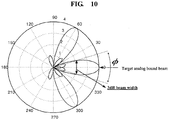
- the 3dB beamwidth ⁇ ⁇ 3 dB is calculated into '0.866 x (2/3) x (180/ ⁇ ) ⁇ 33.8 °'.
- an operating range of a digital beamforming can be represented as Formula 22. ⁇ ⁇ ⁇ 3 ⁇ dB 2 ⁇ ⁇ N t RF ⁇ ⁇ ⁇ 3 ⁇ dB 2
- PMI is determined in consideration of ⁇ in Formula 22.
- ⁇ means a steering angle of a digital beamforming.
- PMI v of a beam steering vector t can be determined. Namely, the configuration shown in Formula 23 is determined.
- v v 1 v 2 ⁇ v N RF
- FIG. 10 shows an operating range of a digital beam in consideration of 3dB beamwidth if an analog beamforming is performed at 0° or ⁇ 60°.
- Table 2 shows a correlation between a parameter ⁇ and an effective range of a beam bound vector.
- a base station can change a parameter ⁇ to correspond to a communication environment. For instance, in an environment in which users are concentrated, by setting the parameter ⁇ to a low value, it is able to select a PMI that maximizes a beam gain in a user equipment. On the other hand, in an environment in which user equipments are distributed more widely, by raising the parameter ⁇ , a selective range of the OMI is increased to cover a wide range despite that a beam gain is reduced.
- the number N t RF of analog antennas included in each RF chain is assumed as equal for example, by which the present invention is non-limited.
- n antennas may be included in a first RF chain
- k antennas may be included in a second RF chain (where n ⁇ k).
- an effective range ⁇ of an analog beam calculated by Formula 20 is different for each RF chain.
- a first effective range is calculated for the first RF chain based on 0.866 ⁇ ⁇ nd
- a second effective range is calculated for the second RF chain based on 0.866 ⁇ ⁇ kd .
- a base station is able to determine an effective range of a final analog beam which is to be applied in common to all RF chains. For instance, if the effective ranges calculated for the respective RF chains are different from each other, the base station is able to determine a minimum effective range among the calculated effective ranges as a final effective range. According to another embodiment, the base station may be able to determine a maximum effective range among the calculated effective ranges as a final effective range. According to another embodiment, the base station can determine a final effective range by averaging the calculated effective ranges. According to another embodiment, the base station can determine a final effective range by a leaner function of applying prescribed weights to the calculated effective ranges.
- the base station can determine an effective range set for the reference RF chain as a final effective range.
- a PMI for a digital beamforming should be adjusted together.
- a codebook is designed to enable a digital beam to be located in an effective range and a PMI should be selected from the corresponding codebook.
- Table 3 shows one example of a codebook according to one embodiment of the present invention.
- a steering angle for performing an analog beamforming is limitative.
- a fine extent of the steering angle is represented as a resolution of the analog beamforming.
- a case that a beamforming is possible by 30° unit like Case 1: ⁇ 0, 30, 60 ... ⁇ has a resolution lower than that of a case that a beamforming is possible by 5° unit like Case 2: ⁇ 0, 5, 10 ... ⁇ .
- a maximum resolution of an analog beamforming is determined by mechanical performance of an analog device.
- a resolution limit of a phase shifter configured to perform an analog beamforming is limitative, an analog beamforming has difficulty in performing a beamforming by fine unit like a digital beamforming.
- a maximum resolution of a supportable analog beamforming is determined in advance.
- effective ranges may overlap with each other depending on a parameter ⁇ .
- an effective range of a first analog beam having a steering angle set to 0 degree is assumed as ranging between -16.5 degrees and +16.5 degrees approximately and an effective range of a second analog beam having a steering angle set to 30 degrees is assumed as ranging between 13.5 degrees and +46.5 degrees approximately.
- a range between 13.5 degrees and 16.6 degrees belongs to the effective range of each of the first analog beam and the second analog beam.
- a PMI of a first digital beam corresponding to the first analog beam may be equal to a PMI of a second digital beam corresponding to the second analog beam.
- some PMIs in a codebook may overlap with each other.
- FIG. 11 shows a case that PMIs overlap with each other.
- the effective range is adjusted by a parameter ⁇ .
- the reason for this is that a user equipment located in an overlapping area may experience interference caused by a beamforming for another user equipment.
- a resolution of a digital beam can be determined depending on an effective range of an analog beam. For instance, if an effective range increases, an interval between selectable digital beams may increase. If an effective range decreases, an interval between selectable digital beams may decrease. Although an effective range is changed, the number of selectable PMIs can be maintained constantly.
- the number of digital beams formable in a first effective range of a first analog beam is N i
- the N i can be maintained intact.
- an interval between digital beams is changed. This corresponds to a resolution change of a digital beam.
- a steering angle i.e., boresight
- a PMI for the interval-changed digital beam should be newly defined.
- PMI sets (e.g., codebook) differing from each other in resolution may be set in advance. Based on an effective range or a parameter ⁇ , the base station can determined whether to use the PMI set.
- a base station may reuse a single codebook.
- a PMI of a codebook can be modified in accordance with an effective range or a parameter ⁇ .
- a plurality of PMI sets differing from each other in resolution per effective range in a single beam bound vector are defined.
- the number (L) of PMIs available for an effective range L1 is equal to the number (L) of PMIs available for an effective range L2, it is P 1 L 1 ⁇ P 1 L 2 .
- a digital beam formed on the basis of P 1 L 1 may be located in a direction different from that of a digital beam formed on the basis of P 1 L 2 .
- a base station is able to adjust a resolution of an analog beam by a beam bound vector in accordance with an effective range.
- a maximum resolution of an analog beamforming is determined by performance of a phase shifter.
- a steering angle of an analog beamformer F RF ) is set to 0°, ⁇ 30°, or ⁇ 60°, a blank of 10° is generated from each beam unit.
- a beamforming precoder is designed in consideration of a range in which an analog beam can be effectively transmitted.
- a hybrid beamformer is configured to operate in a manner that an analog beamforming and a digital beamforming are basically coupled together.
- an applicable range of a digital PMI can be determined and designed through the relation between an analog beam and RF chain.
- An analog beam is estimated in accordance with the number of analog chains connected to each RF chain, whereby a digital beamforming PMI is designed.
- the present embodiments are applicable to various combinations of transmitters and receivers.
- the present embodiments are applicable to an uplink transmission scenario for a user equipment-to-base station transmission, an inter-user equipment (e.g., D2D, V2V, etc.) signal transmission scenario, an inter-base station (e.g., relay, wireless backhaul, etc.) signal transmission scenario and the like.
- an inter-user equipment e.g., D2D, V2V, etc.
- an inter-base station e.g., relay, wireless backhaul, etc.
- FIG. 13 is a diagram of a hybrid beamforming method according to one embodiment of the present invention. Details redundant with the foregoing description shall be omitted from the following description.
- a base station transmits a configuration information of a first reference signal to a user equipment [S1305].
- the configuration information of the first reference signal is transmitted by RRC signaling or may be broadcasted through a system information.
- the configuration information of the first reference signal may include information on a period or frequency for transmitting the first reference signal, information on a resource element to which the first reference signal will be mapped, and the like, by which the signal configuration information may be non-limited.
- the base station transmits the first reference signal through an analog beamforming [S1310].
- the base station can form analog beams for various directions. For instance, the base station can form 12 analog beams for 12 directions by 30° unit. A plurality of analog beams can be formed sequentially in accordance with time.
- the user equipment receives the first reference signal through a first analog beam. Although the first signal is transmitted through a plurality of analog beams, the user equipment is not able to receive the first reference signal through all the analog beams.
- the user equipment receives the first reference signal through at least one analog beam formed in a direction in which the user equipment itself is located.
- the user equipment transmits information on the first analog beam [S1320]. For instance, the user equipment can transmit at least one of information on a timing or subframe for receiving the first reference signal, information on an index of the first analog beam, information on a direction of the first analog beam, and information on a gain of the first analog beam to the base station, by which the information is non-limited.
- the first reference signal may be received through a second analog beam as well as through the first analog beam. In this case, it is preferable that the user equipment transmits information on a prescribed beam having a highest gain to the base station.
- a direction of a hybrid beamforming which is described later, can be determined through the information on the first analog beam. For instance, if a boresight of the first analog beam is 30 degrees, it is preferable that an analog beamforming in the hybrid beamforming is performed in a direction of 30 degrees. Moreover, a digital beamforming in the hybrid beamforming is performed at ⁇ 30 degrees (Effective range/2).
- the base station determines an effective range of the first analog beam [S1325].
- the base station sets a minimum gain (G min ) that should be obtained through the first analog beam.
- the base station determines a range of angles at which a gain of a transmission through the first analog beam becomes equal to or greater than the above-set minimum gain. For instance, the effective range can be determined based on Formula 20.
- the base station changes a resolution of the analog beam in accordance with the effective range. For instance, based on a first unit angle for steering the first analog beam and the determined effective range, the base station determines whether a shade of the analog beamforming exists between the first analog beam and the second analog beam steered by the first unit angle. If the base station determines that the shade of the analog beamforming exists, the base station changes the first unit angle into a second unit angle.
- the base station determines a PMI of the digital beamforming [S1325].
- the base station selects a first PMI (precoding matrix index) set from a codebook.
- the base station selects at least one PMI from the first PMI set.
- the first PMI set may be selected based on at least one of a boresight angle of the first analog beam and a first effective range.
- the codebook may include the first effective range having the first PMI set mapped thereto, a first boresight angle to which a plurality of effective ranges including the first effective range are mapped, and a plurality of boresight angles including the first boresight angle.
- the base station is able to determine whether the first PMI (precoding matrix index) set corresponding to the boresight of the first analog beam overlaps with at least one portion of a second PMI set corresponding to a prescribed angle adjacent to the boresight angle of the first analog beam. If the first PMI set and the second PMI set overlap with each other in part at least, the base station is able to select at least one PMI from the first PMI set shown in Table 4 except the overlapping at least one portion.
- first PMI precoding matrix index
- the resolution of the digital beamforming may be changed. For instance, based on the effective range, the base station selects at least one PMI from the codebook shown in Table 5 including the first PMI (precoding matrix index) set corresponding to the first effective range and the second PMI set corresponding to the second effective range. In this case, the number of first PMIs included in the first PMI set may be equal to that of second PMIs included in the second PMI set. Moreover, an interval between digital beams generated by the first PMIs may be different from an interval between digital beams generated by the second PMIs.
- the base station selects at least one PMI from the codebook shown in Table 5 including the first PMI (precoding matrix index) set corresponding to the first effective range and the second PMI set corresponding to the second effective range.
- the number of first PMIs included in the first PMI set may be equal to that of second PMIs included in the second PMI set.
- an interval between digital beams generated by the first PMIs may be different from an interval between digital beams
- the base station transmits downlink data through the hybrid beamforming [S1330]. For instance, based on the effective range and PMI, the base station performs a hybrid beamforming in which a digital beamforming and an analog beamforming are hierarchically coupled together.
- FIG. 14 is a diagram of a configuration of a base station and a user equipment of one example implementation according to the present disclosure.
- a base station 10 and a user equipment 20 shown in FIG. 14 can perform the methods mentioned in the foregoing description and redundant details shall be omitted from the following description.
- a base station 10 may include a receiver 11, a transmitter 12, a processor 13, a memory 14 and a plurality of antennas 15.
- a plurality of the antennas 15 may mean a base station supportive of MIMO transmission and reception.
- the receiver 11 may receive various signals, data and information in uplink from a user equipment.
- the transmitter 12 may transmit various signals, data and information in downlink to a user equipment.
- the processor 13 may control overall operations of the base station 10.
- the processor 13 of the base station 10 may perform a function of operating and processing information received by the base station 10, information to be externally transmitted and the like.
- the memory 14 can store the operated and processed information and the like for a prescribed time and may be substituted with such a component as a buffer (not shown in the drawing) or the like.
- the processor 13 determines an effective range of an analog beam based on a gain of an analog beamforming in a hybrid beamforming. Based on the effective range of the analog beam, the processor 13 determines a precoding matrix for a digital beamforming in the hybrid beamforming. Based on the effective range and the precoding matrix, the processor 13 performs the hybrid beamforming in which the digital beamforming and the analog beamforming are coupled together.
- the transmitter 12 transmits downlink data to the user equipment through the hybrid beamforming.
- a user equipment 20 may include a receiver 21, a transmitter 22, a processor 23, a memory 24 and a plurality of antennas 25.
- a plurality of the antennas 25 may mean a user equipment supportive of MIMO transmission and reception.
- the receiver 21 may receive various signals, data and information in downlink from a base station.
- the transmitter 22 may transmit various signals, data and information in uplink to a base station.
- the processor 23 may control overall operations of the user equipment 20.
- the processor 23 of the user equipment 20 may perform a function of operating and processing information received by the user equipment 20, information to be externally transmitted and the like.
- the memory 24 can store the operated and processed information and the like for a prescribed time and may be substituted with such a component as a buffer (not shown in the drawing) or the like.
- the receiver 21 receives a first reference signal through a first analog beam among a plurality of analog beams formed in different directions by the analog beamforming.
- the receiver 21 receives downlink data through the hybrid beamforming having the analog beamforming and the digital beamforming coupled therein.
- the transmitter 22 transmits information on the first analog beam through which the first reference signal was received to the base station.
- a precoding matrix for the digital beamforming may be determined based on the effective range of the first analog beam.
- Embodiments of the present invention can be implemented using various means. For instance, embodiments of the present invention can be implemented using hardware, firmware, software and/or any combinations thereof.
- a method according to each of the embodiments of the present invention can be implemented by at least one selected from the group consisting of ASICs (application specific integrated circuits), DSPs (digital signal processors), DSPDs (digital signal processing devices), PLDs (programmable logic devices), FPGAs (field programmable gate arrays), processor, controller, microcontroller, microprocessor and the like.
- ASICs application specific integrated circuits
- DSPs digital signal processors
- DSPDs digital signal processing devices
- PLDs programmable logic devices
- FPGAs field programmable gate arrays
- processor controller, microcontroller, microprocessor and the like.
- a method according to each of the embodiments of the present invention can be implemented by modules, procedures, and/or functions for performing the above-explained functions or operations.
- Software code is stored in a memory unit and is then drivable by a processor.
- the memory unit is provided within or outside the processor to exchange data with the processor through the various means known to the public.
- embodiments of the present invention are applicable to various kinds of mobile communication systems.
Applications Claiming Priority (2)
| Application Number | Priority Date | Filing Date | Title |
|---|---|---|---|
| US201461969277P | 2014-03-24 | 2014-03-24 | |
| PCT/KR2015/001497 WO2015147445A1 (en) | 2014-03-24 | 2015-02-13 | Method of performing a hybrid beamforming in a wireless communication system and apparatus therefor |
Publications (3)
| Publication Number | Publication Date |
|---|---|
| EP3123626A1 EP3123626A1 (en) | 2017-02-01 |
| EP3123626A4 EP3123626A4 (en) | 2017-11-08 |
| EP3123626B1 true EP3123626B1 (en) | 2019-05-01 |
Family
ID=54195908
Family Applications (1)
| Application Number | Title | Priority Date | Filing Date |
|---|---|---|---|
| EP15769817.6A Active EP3123626B1 (en) | 2014-03-24 | 2015-02-13 | Method of performing a hybrid beamforming in a wireless communication system and apparatus therefor |
Country Status (5)
| Country | Link |
|---|---|
| US (1) | US10009084B2 (zh) |
| EP (1) | EP3123626B1 (zh) |
| KR (1) | KR101871726B1 (zh) |
| CN (1) | CN106063148B (zh) |
| WO (1) | WO2015147445A1 (zh) |
Families Citing this family (46)
| Publication number | Priority date | Publication date | Assignee | Title |
|---|---|---|---|---|
| ES2764390T3 (es) * | 2015-04-10 | 2020-06-03 | Huawei Tech Co Ltd | Método y dispositivo de transmisión de datos |
| CN106921423B (zh) * | 2015-12-28 | 2020-02-07 | 电信科学技术研究院 | 一种确定模拟波束的方法和设备 |
| CN106921990B (zh) * | 2015-12-28 | 2019-09-17 | 电信科学技术研究院 | 一种模拟通道测量方法及基站 |
| US9853702B1 (en) * | 2016-01-13 | 2017-12-26 | Keysight Technologies, Inc. | Methods for channel estimation in OFDMA based hybrid beamforming (HBF) systems |
| US10743272B2 (en) | 2016-02-16 | 2020-08-11 | Cable Television Laboratories, Inc. | Coordinated beamforming |
| CN108886826B (zh) * | 2016-04-11 | 2022-06-28 | 梁平 | 用于无线多天线和频分双工系统的混合波束成形方法 |
| CN109155660B (zh) * | 2016-05-12 | 2022-08-30 | 交互数字专利控股公司 | 用于在毫米波无线局域网络中波束成形反馈的系统和方法 |
| US10141993B2 (en) | 2016-06-16 | 2018-11-27 | Intel Corporation | Modular antenna array beam forming |
| US9806777B1 (en) * | 2016-06-24 | 2017-10-31 | Intel Corporation | Communication device and a method for beamforming |
| WO2018026181A1 (ko) * | 2016-08-05 | 2018-02-08 | 엘지전자 주식회사 | 무선 통신 시스템에서 단말 및 기지국의 신호 송수신 방법 및 이를 지원하는 장치 |
| WO2018076362A1 (en) * | 2016-10-31 | 2018-05-03 | Southeast University | Systems and methods for wireless communication with per-beam signal synchronization |
| US10305567B2 (en) | 2016-11-03 | 2019-05-28 | Futurewei Technologies, Inc. | System and method for hierarchal beamforming and rank adaptation for hybrid antenna architecture |
| US10582397B2 (en) * | 2016-11-09 | 2020-03-03 | Qualcomm Incorporated | Beam refinement reference signal transmissions during control symbol |
| CN106452535B (zh) * | 2016-11-24 | 2019-06-07 | 北京邮电大学 | 一种盲信道下的混合波束成形方法及装置 |
| KR20180060882A (ko) | 2016-11-28 | 2018-06-07 | 삼성전자주식회사 | 무선 통신 시스템에서의 빔포밍을 이용한 신호 전송 방법 및 장치 |
| WO2018097411A1 (ko) * | 2016-11-28 | 2018-05-31 | 삼성전자 주식회사 | 무선 통신 시스템에서의 빔포밍을 이용한 신호 전송 방법 및 장치 |
| WO2018098634A1 (zh) * | 2016-11-29 | 2018-06-07 | 华为技术有限公司 | 一种收发信机、基站及信号处理方法 |
| CN106792748B (zh) * | 2016-12-20 | 2020-03-03 | 北京小米移动软件有限公司 | 数据传输方法、装置、基站和终端 |
| KR102448673B1 (ko) * | 2017-01-23 | 2022-09-29 | 한국전자통신연구원 | 무선 통신 시스템에서 다중 안테나를 사용한 통신 방법 및 장치 |
| US10362589B2 (en) * | 2017-01-23 | 2019-07-23 | Electronics And Telecommunications Research Institute | Communication method and apparatus using multiple antennas in wireless communication system |
| CN108365876A (zh) * | 2017-01-26 | 2018-08-03 | 中国移动通信有限公司研究院 | 一种数字波束成形码本生成方法及设备 |
| US10404433B2 (en) * | 2017-01-31 | 2019-09-03 | Qualcomm Incorporated | Matrix-based techniques for mapping resource elements to ports for reference signals |
| CN108471324A (zh) * | 2017-02-23 | 2018-08-31 | 索尼公司 | 电子设备、通信装置和信号处理方法 |
| US10716013B2 (en) | 2017-03-24 | 2020-07-14 | Qualcomm Incorporated | Beam refinement for millimeter wave (MMW) system |
| CN108736941A (zh) * | 2017-04-18 | 2018-11-02 | 中国移动通信有限公司研究院 | 一种数据传输方法、基站及终端 |
| CN108964723A (zh) * | 2017-05-17 | 2018-12-07 | 索尼公司 | 电子设备和通信方法 |
| CN109004366B (zh) * | 2017-06-06 | 2021-07-16 | 华为技术有限公司 | 一种天线装置以及波束调整的方法 |
| CN107294590B (zh) * | 2017-06-20 | 2020-08-28 | 电子科技大学 | 一种基于上行训练的数模混合波束赋形方法 |
| CN109219062B (zh) * | 2017-06-30 | 2022-04-01 | 中国移动通信有限公司研究院 | 一种波束的确定方法、终端及网络侧设备 |
| CN111034064B (zh) * | 2017-08-10 | 2021-12-31 | 华为技术有限公司 | 具有波束选择技术的协同侧链干扰管理 |
| CN109660284A (zh) | 2017-10-11 | 2019-04-19 | 索尼公司 | 无线通信系统中的电子设备、通信方法和存储介质 |
| TWI645689B (zh) | 2017-12-15 | 2018-12-21 | 財團法人工業技術研究院 | 具備混合式波束成型的無線通訊裝置及其之控制方法 |
| CN108809397B (zh) | 2018-06-27 | 2020-06-30 | 东南大学 | 多天线系统中高功效数模混合波束成形方法、装置及设备 |
| US10892807B2 (en) * | 2018-06-27 | 2021-01-12 | Qualcomm Incorporated | Codebook adaptation |
| CN109120316B (zh) * | 2018-09-03 | 2020-05-22 | 杭州电子科技大学 | 一种基于最大化最小相位差值的混合波束成形方法 |
| KR102158206B1 (ko) * | 2018-11-14 | 2020-09-22 | 고려대학교 산학협력단 | 하이브리드 빔포머 필터 설계 장치 및 방법 |
| EP3915199A1 (en) * | 2019-01-21 | 2021-12-01 | Telefonaktiebolaget Lm Ericsson (Publ) | Methods, apparatus and machine-readable medium relating to adjustment of beam gain in wireless communication |
| KR102193752B1 (ko) * | 2019-08-28 | 2020-12-21 | 세종대학교 산학협력단 | 채널 용량 향상을 위한 하이브리드 빔포밍 시스템 기반의 빔 방사 각도 추정 장치 및 그 방법 |
| CN112584444B (zh) * | 2019-09-27 | 2021-09-24 | 上海朗帛通信技术有限公司 | 一种被用于无线通信的方法和设备 |
| KR102313916B1 (ko) * | 2020-06-25 | 2021-10-18 | 세종대학교 산학협력단 | 에너지 효율 향상을 위한 하이브리드 빔포밍 시스템 |
| US11374796B2 (en) | 2020-10-15 | 2022-06-28 | Samsung Electronics Co., Ltd. | Compressive sensing based channel recovery considering time variation of the channel |
| US11147069B1 (en) * | 2021-03-05 | 2021-10-12 | At&T Intellectual Property I, L.P. | Enhanced base station downlink |
| CN113225113B (zh) * | 2021-03-25 | 2022-07-05 | 深圳航天科技创新研究院 | 预编码方法、装置、系统及计算机可读存储介质 |
| KR102287794B1 (ko) * | 2021-04-29 | 2021-08-09 | 세종대학교산학협력단 | 밀리미터파 기반의 다중 사용자 대규모 mimo 기반의 하이브리드 빔포밍 시스템 및 이에 적용되는 아날로그 프리코더 행렬 획득 방법 |
| US11937175B2 (en) * | 2022-01-04 | 2024-03-19 | Rakuten Symphony Singapore Pte. Ltd. | Automatic cell range |
| CN115314081B (zh) * | 2022-04-12 | 2023-08-01 | 中国人民解放军战略支援部队航天工程大学 | 一种低轨通信卫星空间资源管理与优化方法 |
Family Cites Families (11)
| Publication number | Priority date | Publication date | Assignee | Title |
|---|---|---|---|---|
| US7248841B2 (en) * | 2000-06-13 | 2007-07-24 | Agee Brian G | Method and apparatus for optimization of wireless multipoint electromagnetic communication networks |
| US8363744B2 (en) * | 2001-06-10 | 2013-01-29 | Aloft Media, Llc | Method and system for robust, secure, and high-efficiency voice and packet transmission over ad-hoc, mesh, and MIMO communication networks |
| KR101303626B1 (ko) * | 2011-01-06 | 2013-09-11 | 서강대학교산학협력단 | 피사체를 진단하는 진단시스템, 피사체에 대한 진단영상을 제공하는 의료영상시스템 및 피사체에 대한 진단영상을 표시하는 방법 |
| US9344176B2 (en) * | 2011-08-19 | 2016-05-17 | Quintel Technology Limited | Method and apparatus for providing elevation plane spatial beamforming |
| US9444534B2 (en) | 2012-02-06 | 2016-09-13 | Samsung Electronics Co., Ltd. | Apparatus and method for low complexity spatial division multiple access in a millimeter wave mobile communication system |
| US9478857B2 (en) * | 2012-03-02 | 2016-10-25 | Samsung Electronics Co., Ltd. | Apparatus and method for controlling adaptive beamforming gain in wireless communication system |
| KR20130110396A (ko) * | 2012-03-29 | 2013-10-10 | 삼성전자주식회사 | 아날로그/디지털 혼합 빔 포밍 시스템에서 기준 신호 생성을 위한 방법 및 장치 |
| KR20130127347A (ko) * | 2012-05-10 | 2013-11-22 | 삼성전자주식회사 | 아날로그 및 디지털 하이브리드 빔포밍을 통한 통신 방법 및 장치 |
| US9935699B2 (en) | 2012-06-22 | 2018-04-03 | Samsung Electronics Co., Ltd. | Communication method and apparatus using beamforming in a wireless communication system |
| KR101998856B1 (ko) * | 2013-01-28 | 2019-07-11 | 삼성전자주식회사 | 무선통신시스템에서의 송/수신 장치 및 방법 |
| WO2015137636A2 (en) | 2014-03-13 | 2015-09-17 | Lg Electronics Inc. | Method of feedback for beamforming in a wireless communication system and apparatus therefor |
-
2015
- 2015-02-13 WO PCT/KR2015/001497 patent/WO2015147445A1/en active Application Filing
- 2015-02-13 CN CN201580009049.6A patent/CN106063148B/zh not_active Expired - Fee Related
- 2015-02-13 EP EP15769817.6A patent/EP3123626B1/en active Active
- 2015-02-13 US US15/113,999 patent/US10009084B2/en active Active
- 2015-02-13 KR KR1020167019730A patent/KR101871726B1/ko active IP Right Grant
Non-Patent Citations (1)
| Title |
|---|
| None * |
Also Published As
| Publication number | Publication date |
|---|---|
| CN106063148B (zh) | 2020-02-14 |
| WO2015147445A1 (en) | 2015-10-01 |
| KR101871726B1 (ko) | 2018-06-27 |
| US10009084B2 (en) | 2018-06-26 |
| EP3123626A1 (en) | 2017-02-01 |
| KR20160102488A (ko) | 2016-08-30 |
| EP3123626A4 (en) | 2017-11-08 |
| CN106063148A (zh) | 2016-10-26 |
| US20160344463A1 (en) | 2016-11-24 |
Similar Documents
| Publication | Publication Date | Title |
|---|---|---|
| EP3123626B1 (en) | Method of performing a hybrid beamforming in a wireless communication system and apparatus therefor | |
| EP3117533B1 (en) | Method of feedback for beamforming in a wireless communication system and apparatus therefor | |
| EP3185437B1 (en) | Method for determining weight for beamforming in wireless communication system and apparatus therefor | |
| US10652048B2 (en) | 3-D MIMO communication system, radio base station, and user equipment | |
| US9893789B2 (en) | Method of transmitting a reference signal in a wireless communication system and apparatus therefor | |
| US10200100B2 (en) | Method for transmitting and receiving feedback information in wireless communication system and device for same | |
| US9935700B2 (en) | Beam scanning method for hybrid beamforming in wireless communication system and apparatus therefor | |
| EP2975875B1 (en) | Method and device for reporting channel state information in wireless communication system | |
| US10050689B2 (en) | Method of determining a weight of a digital beamforming in a wireless communication system and apparatus therefor | |
| US9331386B2 (en) | Beamformed downlink communications for a multiple antenna system | |
| US9941945B2 (en) | Method for performing mobility-based beamforming in wireless communication system, and apparatus therefor | |
| US10090899B2 (en) | Method for determining precoder for hybrid beamforming in wireless communication system, and apparatus therefor | |
| US10469151B2 (en) | Beam scanning method of terminal for hybrid beam forming in wireless communication system, and device for same | |
| KR20180065554A (ko) | 무선 통신 시스템에서 빔포밍을 수행하는 방법 및 이를 위한 장치 | |
| EP3633873B1 (en) | Method for transmitting feedback information in wireless communication system and apparatus therefor |
Legal Events
| Date | Code | Title | Description |
|---|---|---|---|
| PUAI | Public reference made under article 153(3) epc to a published international application that has entered the european phase |
Free format text: ORIGINAL CODE: 0009012 |
|
| STAA | Information on the status of an ep patent application or granted ep patent |
Free format text: STATUS: REQUEST FOR EXAMINATION WAS MADE |
|
| 17P | Request for examination filed |
Effective date: 20160824 |
|
| AK | Designated contracting states |
Kind code of ref document: A1 Designated state(s): AL AT BE BG CH CY CZ DE DK EE ES FI FR GB GR HR HU IE IS IT LI LT LU LV MC MK MT NL NO PL PT RO RS SE SI SK SM TR |
|
| AX | Request for extension of the european patent |
Extension state: BA ME |
|
| DAX | Request for extension of the european patent (deleted) | ||
| A4 | Supplementary search report drawn up and despatched |
Effective date: 20171011 |
|
| RIC1 | Information provided on ipc code assigned before grant |
Ipc: H04B 7/06 20060101ALI20171005BHEP Ipc: H04B 7/04 20170101AFI20171005BHEP |
|
| GRAP | Despatch of communication of intention to grant a patent |
Free format text: ORIGINAL CODE: EPIDOSNIGR1 |
|
| STAA | Information on the status of an ep patent application or granted ep patent |
Free format text: STATUS: GRANT OF PATENT IS INTENDED |
|
| INTG | Intention to grant announced |
Effective date: 20181220 |
|
| GRAS | Grant fee paid |
Free format text: ORIGINAL CODE: EPIDOSNIGR3 |
|
| GRAA | (expected) grant |
Free format text: ORIGINAL CODE: 0009210 |
|
| STAA | Information on the status of an ep patent application or granted ep patent |
Free format text: STATUS: THE PATENT HAS BEEN GRANTED |
|
| AK | Designated contracting states |
Kind code of ref document: B1 Designated state(s): AL AT BE BG CH CY CZ DE DK EE ES FI FR GB GR HR HU IE IS IT LI LT LU LV MC MK MT NL NO PL PT RO RS SE SI SK SM TR |
|
| REG | Reference to a national code |
Ref country code: GB Ref legal event code: FG4D |
|
| REG | Reference to a national code |
Ref country code: CH Ref legal event code: EP Ref country code: AT Ref legal event code: REF Ref document number: 1128313 Country of ref document: AT Kind code of ref document: T Effective date: 20190515 |
|
| REG | Reference to a national code |
Ref country code: DE Ref legal event code: R096 Ref document number: 602015029379 Country of ref document: DE |
|
| REG | Reference to a national code |
Ref country code: IE Ref legal event code: FG4D |
|
| REG | Reference to a national code |
Ref country code: NL Ref legal event code: MP Effective date: 20190501 |
|
| REG | Reference to a national code |
Ref country code: LT Ref legal event code: MG4D |
|
| PG25 | Lapsed in a contracting state [announced via postgrant information from national office to epo] |
Ref country code: ES Free format text: LAPSE BECAUSE OF FAILURE TO SUBMIT A TRANSLATION OF THE DESCRIPTION OR TO PAY THE FEE WITHIN THE PRESCRIBED TIME-LIMIT Effective date: 20190501 Ref country code: AL Free format text: LAPSE BECAUSE OF FAILURE TO SUBMIT A TRANSLATION OF THE DESCRIPTION OR TO PAY THE FEE WITHIN THE PRESCRIBED TIME-LIMIT Effective date: 20190501 Ref country code: SE Free format text: LAPSE BECAUSE OF FAILURE TO SUBMIT A TRANSLATION OF THE DESCRIPTION OR TO PAY THE FEE WITHIN THE PRESCRIBED TIME-LIMIT Effective date: 20190501 Ref country code: PT Free format text: LAPSE BECAUSE OF FAILURE TO SUBMIT A TRANSLATION OF THE DESCRIPTION OR TO PAY THE FEE WITHIN THE PRESCRIBED TIME-LIMIT Effective date: 20190901 Ref country code: FI Free format text: LAPSE BECAUSE OF FAILURE TO SUBMIT A TRANSLATION OF THE DESCRIPTION OR TO PAY THE FEE WITHIN THE PRESCRIBED TIME-LIMIT Effective date: 20190501 Ref country code: NO Free format text: LAPSE BECAUSE OF FAILURE TO SUBMIT A TRANSLATION OF THE DESCRIPTION OR TO PAY THE FEE WITHIN THE PRESCRIBED TIME-LIMIT Effective date: 20190801 Ref country code: HR Free format text: LAPSE BECAUSE OF FAILURE TO SUBMIT A TRANSLATION OF THE DESCRIPTION OR TO PAY THE FEE WITHIN THE PRESCRIBED TIME-LIMIT Effective date: 20190501 Ref country code: LT Free format text: LAPSE BECAUSE OF FAILURE TO SUBMIT A TRANSLATION OF THE DESCRIPTION OR TO PAY THE FEE WITHIN THE PRESCRIBED TIME-LIMIT Effective date: 20190501 Ref country code: NL Free format text: LAPSE BECAUSE OF FAILURE TO SUBMIT A TRANSLATION OF THE DESCRIPTION OR TO PAY THE FEE WITHIN THE PRESCRIBED TIME-LIMIT Effective date: 20190501 |
|
| PG25 | Lapsed in a contracting state [announced via postgrant information from national office to epo] |
Ref country code: RS Free format text: LAPSE BECAUSE OF FAILURE TO SUBMIT A TRANSLATION OF THE DESCRIPTION OR TO PAY THE FEE WITHIN THE PRESCRIBED TIME-LIMIT Effective date: 20190501 Ref country code: BG Free format text: LAPSE BECAUSE OF FAILURE TO SUBMIT A TRANSLATION OF THE DESCRIPTION OR TO PAY THE FEE WITHIN THE PRESCRIBED TIME-LIMIT Effective date: 20190801 Ref country code: GR Free format text: LAPSE BECAUSE OF FAILURE TO SUBMIT A TRANSLATION OF THE DESCRIPTION OR TO PAY THE FEE WITHIN THE PRESCRIBED TIME-LIMIT Effective date: 20190802 Ref country code: LV Free format text: LAPSE BECAUSE OF FAILURE TO SUBMIT A TRANSLATION OF THE DESCRIPTION OR TO PAY THE FEE WITHIN THE PRESCRIBED TIME-LIMIT Effective date: 20190501 |
|
| REG | Reference to a national code |
Ref country code: AT Ref legal event code: MK05 Ref document number: 1128313 Country of ref document: AT Kind code of ref document: T Effective date: 20190501 |
|
| PG25 | Lapsed in a contracting state [announced via postgrant information from national office to epo] |
Ref country code: IS Free format text: LAPSE BECAUSE OF FAILURE TO SUBMIT A TRANSLATION OF THE DESCRIPTION OR TO PAY THE FEE WITHIN THE PRESCRIBED TIME-LIMIT Effective date: 20190901 |
|
| PG25 | Lapsed in a contracting state [announced via postgrant information from national office to epo] |
Ref country code: DK Free format text: LAPSE BECAUSE OF FAILURE TO SUBMIT A TRANSLATION OF THE DESCRIPTION OR TO PAY THE FEE WITHIN THE PRESCRIBED TIME-LIMIT Effective date: 20190501 Ref country code: AT Free format text: LAPSE BECAUSE OF FAILURE TO SUBMIT A TRANSLATION OF THE DESCRIPTION OR TO PAY THE FEE WITHIN THE PRESCRIBED TIME-LIMIT Effective date: 20190501 Ref country code: EE Free format text: LAPSE BECAUSE OF FAILURE TO SUBMIT A TRANSLATION OF THE DESCRIPTION OR TO PAY THE FEE WITHIN THE PRESCRIBED TIME-LIMIT Effective date: 20190501 Ref country code: RO Free format text: LAPSE BECAUSE OF FAILURE TO SUBMIT A TRANSLATION OF THE DESCRIPTION OR TO PAY THE FEE WITHIN THE PRESCRIBED TIME-LIMIT Effective date: 20190501 Ref country code: SK Free format text: LAPSE BECAUSE OF FAILURE TO SUBMIT A TRANSLATION OF THE DESCRIPTION OR TO PAY THE FEE WITHIN THE PRESCRIBED TIME-LIMIT Effective date: 20190501 Ref country code: CZ Free format text: LAPSE BECAUSE OF FAILURE TO SUBMIT A TRANSLATION OF THE DESCRIPTION OR TO PAY THE FEE WITHIN THE PRESCRIBED TIME-LIMIT Effective date: 20190501 |
|
| REG | Reference to a national code |
Ref country code: DE Ref legal event code: R097 Ref document number: 602015029379 Country of ref document: DE |
|
| PG25 | Lapsed in a contracting state [announced via postgrant information from national office to epo] |
Ref country code: SM Free format text: LAPSE BECAUSE OF FAILURE TO SUBMIT A TRANSLATION OF THE DESCRIPTION OR TO PAY THE FEE WITHIN THE PRESCRIBED TIME-LIMIT Effective date: 20190501 Ref country code: IT Free format text: LAPSE BECAUSE OF FAILURE TO SUBMIT A TRANSLATION OF THE DESCRIPTION OR TO PAY THE FEE WITHIN THE PRESCRIBED TIME-LIMIT Effective date: 20190501 |
|
| PLBE | No opposition filed within time limit |
Free format text: ORIGINAL CODE: 0009261 |
|
| STAA | Information on the status of an ep patent application or granted ep patent |
Free format text: STATUS: NO OPPOSITION FILED WITHIN TIME LIMIT |
|
| PG25 | Lapsed in a contracting state [announced via postgrant information from national office to epo] |
Ref country code: TR Free format text: LAPSE BECAUSE OF FAILURE TO SUBMIT A TRANSLATION OF THE DESCRIPTION OR TO PAY THE FEE WITHIN THE PRESCRIBED TIME-LIMIT Effective date: 20190501 |
|
| 26N | No opposition filed |
Effective date: 20200204 |
|
| PG25 | Lapsed in a contracting state [announced via postgrant information from national office to epo] |
Ref country code: PL Free format text: LAPSE BECAUSE OF FAILURE TO SUBMIT A TRANSLATION OF THE DESCRIPTION OR TO PAY THE FEE WITHIN THE PRESCRIBED TIME-LIMIT Effective date: 20190501 |
|
| PGFP | Annual fee paid to national office [announced via postgrant information from national office to epo] |
Ref country code: DE Payment date: 20200106 Year of fee payment: 6 |
|
| PG25 | Lapsed in a contracting state [announced via postgrant information from national office to epo] |
Ref country code: SI Free format text: LAPSE BECAUSE OF FAILURE TO SUBMIT A TRANSLATION OF THE DESCRIPTION OR TO PAY THE FEE WITHIN THE PRESCRIBED TIME-LIMIT Effective date: 20190501 |
|
| REG | Reference to a national code |
Ref country code: CH Ref legal event code: PL |
|
| GBPC | Gb: european patent ceased through non-payment of renewal fee |
Effective date: 20200213 |
|
| REG | Reference to a national code |
Ref country code: BE Ref legal event code: MM Effective date: 20200229 |
|
| PG25 | Lapsed in a contracting state [announced via postgrant information from national office to epo] |
Ref country code: MC Free format text: LAPSE BECAUSE OF FAILURE TO SUBMIT A TRANSLATION OF THE DESCRIPTION OR TO PAY THE FEE WITHIN THE PRESCRIBED TIME-LIMIT Effective date: 20190501 Ref country code: LU Free format text: LAPSE BECAUSE OF NON-PAYMENT OF DUE FEES Effective date: 20200213 |
|
| PG25 | Lapsed in a contracting state [announced via postgrant information from national office to epo] |
Ref country code: LI Free format text: LAPSE BECAUSE OF NON-PAYMENT OF DUE FEES Effective date: 20200229 Ref country code: CH Free format text: LAPSE BECAUSE OF NON-PAYMENT OF DUE FEES Effective date: 20200229 |
|
| PG25 | Lapsed in a contracting state [announced via postgrant information from national office to epo] |
Ref country code: FR Free format text: LAPSE BECAUSE OF NON-PAYMENT OF DUE FEES Effective date: 20200229 Ref country code: GB Free format text: LAPSE BECAUSE OF NON-PAYMENT OF DUE FEES Effective date: 20200213 Ref country code: IE Free format text: LAPSE BECAUSE OF NON-PAYMENT OF DUE FEES Effective date: 20200213 |
|
| PG25 | Lapsed in a contracting state [announced via postgrant information from national office to epo] |
Ref country code: BE Free format text: LAPSE BECAUSE OF NON-PAYMENT OF DUE FEES Effective date: 20200229 |
|
| REG | Reference to a national code |
Ref country code: DE Ref legal event code: R119 Ref document number: 602015029379 Country of ref document: DE |
|
| PG25 | Lapsed in a contracting state [announced via postgrant information from national office to epo] |
Ref country code: DE Free format text: LAPSE BECAUSE OF NON-PAYMENT OF DUE FEES Effective date: 20210901 |
|
| PG25 | Lapsed in a contracting state [announced via postgrant information from national office to epo] |
Ref country code: MT Free format text: LAPSE BECAUSE OF FAILURE TO SUBMIT A TRANSLATION OF THE DESCRIPTION OR TO PAY THE FEE WITHIN THE PRESCRIBED TIME-LIMIT Effective date: 20190501 Ref country code: CY Free format text: LAPSE BECAUSE OF FAILURE TO SUBMIT A TRANSLATION OF THE DESCRIPTION OR TO PAY THE FEE WITHIN THE PRESCRIBED TIME-LIMIT Effective date: 20190501 |
|
| PG25 | Lapsed in a contracting state [announced via postgrant information from national office to epo] |
Ref country code: MK Free format text: LAPSE BECAUSE OF FAILURE TO SUBMIT A TRANSLATION OF THE DESCRIPTION OR TO PAY THE FEE WITHIN THE PRESCRIBED TIME-LIMIT Effective date: 20190501 |