EP3123279B1 - Suivi du regard à l'aide de contraintes de fixation binoculaire - Google Patents
Suivi du regard à l'aide de contraintes de fixation binoculaire Download PDFInfo
- Publication number
- EP3123279B1 EP3123279B1 EP15713094.9A EP15713094A EP3123279B1 EP 3123279 B1 EP3123279 B1 EP 3123279B1 EP 15713094 A EP15713094 A EP 15713094A EP 3123279 B1 EP3123279 B1 EP 3123279B1
- Authority
- EP
- European Patent Office
- Prior art keywords
- gaze
- glints
- eye
- pupil
- bias correction
- Prior art date
- Legal status (The legal status is an assumption and is not a legal conclusion. Google has not performed a legal analysis and makes no representation as to the accuracy of the status listed.)
- Active
Links
Images


Classifications
-
- G—PHYSICS
- G06—COMPUTING; CALCULATING OR COUNTING
- G06F—ELECTRIC DIGITAL DATA PROCESSING
- G06F3/00—Input arrangements for transferring data to be processed into a form capable of being handled by the computer; Output arrangements for transferring data from processing unit to output unit, e.g. interface arrangements
- G06F3/01—Input arrangements or combined input and output arrangements for interaction between user and computer
- G06F3/011—Arrangements for interaction with the human body, e.g. for user immersion in virtual reality
- G06F3/013—Eye tracking input arrangements
-
- G—PHYSICS
- G06—COMPUTING; CALCULATING OR COUNTING
- G06T—IMAGE DATA PROCESSING OR GENERATION, IN GENERAL
- G06T7/00—Image analysis
- G06T7/0002—Inspection of images, e.g. flaw detection
-
- G—PHYSICS
- G06—COMPUTING; CALCULATING OR COUNTING
- G06T—IMAGE DATA PROCESSING OR GENERATION, IN GENERAL
- G06T7/00—Image analysis
- G06T7/80—Analysis of captured images to determine intrinsic or extrinsic camera parameters, i.e. camera calibration
- G06T7/85—Stereo camera calibration
-
- G—PHYSICS
- G06—COMPUTING; CALCULATING OR COUNTING
- G06V—IMAGE OR VIDEO RECOGNITION OR UNDERSTANDING
- G06V40/00—Recognition of biometric, human-related or animal-related patterns in image or video data
- G06V40/10—Human or animal bodies, e.g. vehicle occupants or pedestrians; Body parts, e.g. hands
- G06V40/18—Eye characteristics, e.g. of the iris
- G06V40/19—Sensors therefor
-
- G—PHYSICS
- G06—COMPUTING; CALCULATING OR COUNTING
- G06T—IMAGE DATA PROCESSING OR GENERATION, IN GENERAL
- G06T2207/00—Indexing scheme for image analysis or image enhancement
- G06T2207/10—Image acquisition modality
- G06T2207/10004—Still image; Photographic image
- G06T2207/10012—Stereo images
-
- G—PHYSICS
- G06—COMPUTING; CALCULATING OR COUNTING
- G06T—IMAGE DATA PROCESSING OR GENERATION, IN GENERAL
- G06T2207/00—Indexing scheme for image analysis or image enhancement
- G06T2207/30—Subject of image; Context of image processing
- G06T2207/30196—Human being; Person
Definitions
- Natural user interfaces such as based upon speech recognition, head and skeletal tracking and gesture detection are becoming more widespread to supplement, or in some cases replace, keyboard, pointing device (mouse or stylus) and/or recognized symbol / handwriting input.
- Eye gaze detection is another natural user interface technology.
- CR cross-ratio
- This technology exploits the invariance of a plane projectivity to enable remote gaze estimation of a subject using a single camera in an uncalibrated setup.
- infrared light is projected towards a user, with corneal reflections from the user's eye (glints) sensed by the camera and processed to track the gaze.
- WO 2010/003410 A1 describes a method of performing eye gaze tracking of at least one eye of a user, by determining the position of the central eye. Positions of at least three reflections on the eye are detected and the positions are transformed to spanning a normalized coordinate system spanning a frame of reference. The position of the central eye is detected and transformed to the normalized coordinate system. Data from both eyes may be used to increase the robustness of the method.
- US 2012/0050493 A1 discloses a homography based estimation of the user's gaze jointly optimizing data obtained from two cameras for both eyes of the user.
- CN102176755 A discloses a cross ratio eye gaze estimation method by using data from both eyes in a linear calibration algorithm.
- the invention provides a method as defined in claim 1; a system as defined in claim 5 and one or more machine-readable storage media or hardware logic as defined in claim 8. Further aspects of the invention are outlined in the dependent claims. Embodiments which do not fall within the scope of the claims do not form part of the present invention.
- various examples of the subject matter described herein are directed towards a gaze detection technology based upon data obtained from both eyes and constraints that relate one eye's data to the other eye's data.
- Examples include computing a current gaze location of a subject in a joint error minimization, in which at least four glints are captured in each eye, including computing a current left homography matrix and a current right homography matrix for use with left pupil data and right pupil data in the joint error minimization.
- At least four light sources generate corneal reflections as pairs of left and right glints from a subject's left and right eyes.
- a camera captures a current image containing the left and right glints and left and right pupil data.
- a binocular computation corrector computes left and right homography matrices based upon the left and right glints, for use with the left and right pupil data in a joint computation of a gaze location.
- the binocular computation corrector also may use left and right bias correction homography matrices.
- One or more examples are directed towards capturing an image including a subject's left and right eyes from which left and right glints and left and right pupil center information are extracted as left and right glint data and left and right pupil data, respectively.
- the left and right glint data and the left and right pupil data are used with left and right bias correction matrices to jointly determine a gaze location.
- Various aspects of the technology described herein are generally directed towards eye gaze detection based upon the binocular fixation constraint (where binocular fixation is the process of having both eyes directed at the same location at the same time) for use with cross-ratio-based (homography) techniques.
- binocular fixation is the process of having both eyes directed at the same location at the same time
- cross-ratio-based homoography
- this provides for more accurately estimating eye gaze tracking in cross-ratio-based approaches.
- the binocular fixation constraint may be particularly useful when depth perception (3D eye gaze) is needed in a given scenario.
- left and right bias correction homography matrices are calibrated for a user by using a plurality of gaze position as ground truth for the glints and the pupil center at each gaze point. Note that instead of using a single eye, the glints and pupil data (e.g., pupil centers) from both eyes are captured, along with the pupil data of both eyes, and used at each gaze position in computing the bias correction matrices.
- the glints and pupil data e.g., pupil centers
- left and right cross-ratio homography matrices are computed. Based upon the computed homography matrices and the calibrated bias correction matrices, the current gaze location is jointly computed.
- the joint computation is based upon corresponding pairs of left and right eye glints being constrained by their relationship, namely each left and right glint pair commonly reflects from the same one of the light sources. Further, the joint computation is based upon the pupil data (e.g., pupil centers) being constrained by their gazing at the same gaze location.
- any of the examples herein are non-limiting.
- any number of cameras and light sources that provide a suitable glint pattern
- the algorithms and the like used to detect eye gaze are only examples, and the technology described herein is independent of and not limited to any particular one, and further is able to be adapted as new algorithms are developed.
- the present invention is not limited to any particular embodiments, aspects, concepts, structures, functionalities or examples described herein. Rather, any of the embodiments, aspects, concepts, structures, functionalities or examples described herein are non-limiting, and the present invention may be used various ways that provide benefits and advantages in eye gaze detection in general.
- FIG. 1 is a general block diagram illustrating example components that may be used to perform eye gaze detection / tracking.
- a computing device 102 and display 104 are shown.
- the display 104 may be an external display coupled to the computing device or a display incorporated into the computer device, e.g., its housing.
- a plurality of IR light sources 106(1) -106(m) is shown, along with one or more IR light-sensitive cameras 108(1) -108(n). Note that for cross-ratio-based eye gaze detection, a single camera is typically sufficient, however if present, images from multiple cameras may be processed and combined in some way (e.g., averaged) such as to reduce the effects of noise.
- the light sources may be individual light sources such as laser light emitting diodes (LEDs), and/or LEDs or the like that project through an optical element that diffracts / reflects the light, thereby providing a plurality of light sources.
- LEDs laser light emitting diodes
- any or all of the IR light-sensitive cameras may be combined with visible light cameras.
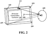
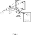
- the camera (or cameras) may be attached to the device, e.g., embedded in an edge (e.g., the camera 208 of FIG. 2 represented by the circled X) or physically coupled to the device, or may be external to the device (e.g., the camera 508 of FIG. 5 ), or a combination of both.
- At least four light sources are needed to provide the glints that are needed to compute the homography, and these light sources are arranged such that there are at least three different directions between any one of them and the others, providing a quadrilateral, e.g., a rectangular pattern of sources 222 - 225 as in FIG. 2 is a typical arrangement. Notwithstanding, other arrangements including more light source are feasible, and, for example, may provide benefits such as providing at least four glints when one of the other glints is not detected.
- a controller 110 may be used to control the operation of the IR light sources 106(1) -106(m) and/or IR light-sensitive cameras 108(1) -108(n), although in one or more implementations the light sources and cameras may be "always-on” whereby no “controller” other than a power source presumably with on/off capabilities is needed.
- IR light is used because it is not noticeable to humans, however in certain situations it may be desirable to use visible light, such as with the subject's eyes wearing contact lenses that block the particular visible light wavelength being used.
- "light source” is not limited to IR wavelengths.
- the one or more cameras 108(1) - 108(n) capture images that are fed to an image processing component 112, including an eye gaze detector 114, which is coupled to a binocular computation corrector 116 (which may include other bias correction) as described herein.
- the image processing component 112 provides an eye gaze detection output 118, such as gaze coordinates representative of where the user is currently gazing in the given frame or the like being processed.
- Such output 118 may be buffered, such as for use with other input (e.g., mouse clicks or gestures), may be consumed by an operating system (e.g., to move a cursor), may be used by an application (e.g., to highlight a menu item) and/or the like.
- the current gaze information may be used to take action with respect to changing a state of a user interface.
- Eye gaze detection may be used for other state changes, e.g., to turn on a display to an active state from a standby or off state, (or vice-versa), possibly in combination with other (e.g., gesture) detection such as an eye-blinking pattern.
- any existing or to-be-developed techniques may be employed to convert sensed glints, pupil data and any other captured features into the eye gaze information output 118. Decisions of one or more as techniques may be combined (e.g., averaged) to make the final output.
- the binocular computation corrector provides the eye gaze detection algorithm 114 with bias-correction that tends to be more accurate than single eye techniques.
- remote gaze tracking systems operate using the infrared light sources to generate corneal reflections, referred to as glints, which are captured as part of the subject's eye images.
- the captured images are processed to extract informative features that are invariant to illumination and viewpoint, such as pupil center, the corneal reflections (e.g., indicative of the eyeball's position) and/or limbus contour.
- FIG. 2 the concept of glints reflected from the IR light source 225 from each eye is shown as being captured by the camera 208 while the user is looking at a current gaze location 226 on the screen.
- glints from the other light sources 222 - 224 are similarly captured at the same time (although only one such set of arrows to the eyes / reflected to the camera is shown in FIG. 2 ).
- FIGS. 3 and 4 show the concept of left and right glint data and pupil data from a geometric representation and image representation, respectively; (note that left and right are reversed in the image 442).
- L 1 - L 4 represent the light sources and G the gaze position relative to a screen 332.
- H L and H R represent the left and right homography matrices, respectively; as described below, these matrices are related by left and right pairs of the glints (e.g., g 1 L g 1 R ) and thus may be represented by the matrix H LR .
- FIGS. 3 and 4 show the concept of left and right glint data and pupil data from a geometric representation and image representation, respectively; (note that left and right are reversed in the image 442).
- L 1 - L 4 represent the light sources and G the gaze position relative to a screen 332.
- H L and H R represent the left and right homography matrices, respectively; as described below, these matrices are related by left and right pairs
- g 1 L ⁇ g 4 L represent the left glints from the light sources L 1 - L 4 , and p L the left pupil center; g 1 R ⁇ g 4 R represent the right glints and p R the right pupil center.
- FIG. 4 shows a usage model of the glint data, extracted from the image 442 via data extraction 444.
- This data including glint data and pupil data for each eye is fed to a the binocular computation corrector 116, which outputs the gaze information 448 (e.g., the screen coordinates or the like) computed from the data to a program 450, such as an application, operating system user interface, a remote device or the like.
- the binocular computation corrector 116 computes a left homography matrix and a right homography matrix, and may use left and right bias correction matrices, to jointly estimate the gaze information.
- an accurate and robust gaze estimation technology is based upon homography-based methods for gaze estimation bias correction, which operates via a bias-correcting homography transformation.
- the bias correcting homography transformation can be computed by solving the point set registration problem from the predicted gaze points by the basic cross-ratio method to ground truth targets on the screen during a calibration training phase. Instead of single eye computations, both eyes are used as set forth below.
- homograph-based methods generally work well at the calibration position because they effectively model the optical and visual axis offsets, as generally represented in FIG. 5 .
- IR infrared
- a camera directed towards the user captures images of the user's eyes.
- the corneal reflection of each light source L i on the eye is called a glint denoted by G 1 - G 4 .
- the detected glints are denoted by g 1 - g 4 .
- p denotes the center of the detected pupil in the image.
- the cross-ratio method assumes that glints Gi's are coplanar. Then, there exists a plane projectivity, expressed as a homography matrix, between Li's and g i 's, and there exists another plane projectivity between G i 's and g i 's.
- the eye optical axis defined by the vector from the corneal center to the pupil center on the eye, is not the same as the visual axis, which defines the actual gaze.
- the angle between the two axes is person-dependent. Therefore, a subject-dependent calibration is used to correct this bias.
- a user is asked to look at a plurality of calibration points (gaze positions) on the screen, which are considered as the ground truth of the gaze calibration points, denoted by G j , with j as the index to the gaze positions. For each gaze position, the process detects the glints in the image, denoted by g i,j , and the pupil center, denoted by p j .
- the process computes the cross-ratio homography, H j , from equation (1).
- each left and right pair of glints are a projection of the same light source, so pairs of glints are related.
- the left and right eyes are looking at the same gaze location. Note however because of noise-related errors and the like, independent left and right eye-estimations of the gaze location may not be the same.
- the relationships between glints may be represented via equations (5) and (6).
- the relationships between pupil-related data e.g., the left and right pupil centers p L and p R , respectively
- the mapping from p L should map to same gaze location G as p R , which may be represented via Equations (7) and (8).
- H LR H R H L ⁇ 1
- H L and H R the following problem needs to be solved: min H L , H R ⁇ i ( ⁇ g i L ⁇ H H L L i ⁇ 2 + ⁇ g i R ⁇ H H R L i ⁇ 2 + 1 2 ⁇ g i R ⁇ H H R H L ⁇ 1 g i L ⁇ 2 + 1 2 ⁇ g i L ⁇ H H L H R ⁇ 1 g i R ⁇ 2
- the coefficient 1/2 in the last two items is used to compensate for double use of the pair g i L g i R in two directions.
- H b L and H b R are left- and right-eye bias-correction homography matrices respectively, which adjust the disparity from the gaze location to the mapped pupil location.
- the gaze point can be jointly estimated by minimizing the re-projection error between the pupil centers in the image and their corresponding estimations from the gaze point using both the cross-ratio and bias-correction homography matrices, i.e., min G ⁇ p L ⁇ H H L H b L G ⁇ 2 + ⁇ p R ⁇ H H R H b R G ⁇ 2
- the noise in the left and right pupil locations is independent, isotropic, and identically distributed.
- the calibration operation comprises three steps.
- a first step is to estimate H j L H j R ) for each gaze position j using equation (6).
- a third step is to separately estimate the bias-correction homography matrices H b L H b R by minimizing the distances between the gaze positions and the corresponding mapped pupil locations in the screen, i.e., min H b L ⁇ j ⁇ P j L ⁇ H H b L G j ⁇ 2 , min H b R ⁇ j ⁇ P j R ⁇ H H b R G j ⁇ 2 ,
- FIG. 6 is a generalized flow diagram showing example steps in online usage of the learned adaptive homography model.
- Step 602 represents the above-described calibration to obtain the left and right bias correction matrices; note that once calibrated, this information may be stored for a subject rather than recalibrated each time.
- Step 604 captures the image, e.g., a frame in a series of frames.
- Step 606 represents an evaluation as to whether both eyes (e.g., four glints in each eye) are suitably captured. If only one eye is captured, the gaze is estimated at step 608 by whichever eye was suitably captured. (Note that if no suitable eye data is available, e.g., the subject eyelids were shut during the frame, the process may jump to step 618 to capture another frame.)
- step 610 processes the image data into the glint data and pupil-related data for use in computing the left and right cross ratio homography matrices (step 612) as described above.
- step 614 uses these matrices along with the bias correction matrices to jointly compute the gaze position as also described above (equation (9)).
- Step 616 outputs the results.
- Step 618 repeats the process for another frame (until eye gaze detection is turned off, for example).
- the frame rate may be configured, and/or some smoothing operation may be used, to prevent too much jumping around.
- step 614 also optionally considers adapting for the current head position of the subject.
- the head position of the subject tends to influence the positions and sizes of the glints that are captured.
- the technology described herein may be combined in a system with another technology based upon head positioning aspects, such as described in copending U.S. Patent application entitled “EYE GAZE TRACKING BASED UPON ADAPTIVE HOMOGRAPHY MAPPING" filed concurrently herewith, attorney docket no. 340833.01 .
- eye gaze detection technology based upon data obtained from both eyes and the constraints that relate one eye's data to the other eye's data. Aspects are directed towards computing a current gaze location of a subject in a joint error minimization, in which at least four glints are captured in each eye, including computing a current left homography matrix and a current right homography matrix for use with left pupil data and right pupil data in the joint error minimization. Computing the current left homography matrix and the current right homography matrix may be based upon minimizing errors using light source locations, left eye glint locations and right eye glint locations.
- Determining the current gaze location may include multiplying the left homography matrix with a left bias correction homography matrix and multiplying the right homography matrix with a right bias correction homography matrix.
- the correction matrices may be computed by obtaining tuples of left eye glint data, pupil data and right eye glint data, pupil data at a plurality of gaze calibration positions.
- the left and right glint data at each gaze calibration position may be used to compute a left and right homography matrix at each gaze position, respectively.
- Left and right screen-mapped pupil locations at each gaze position with the left and right bias correction homography matrices computed by determining a distance between an actual gaze position and the left screen-mapped pupil location, and the distance between an actual gaze position and the right screen-mapped pupil location at each gaze position, respectively.
- At least four light sources generate corneal reflections as pairs of left and right glints from a subject's left and right eyes.
- a camera captures a current image containing the left and right glints and left and right pupil data.
- a binocular computation model computes left and right homography matrices based upon the left and right glints, for use with the left and right pupil data in a joint computation of a gaze location.
- the binocular computation model may use left and right bias correction homography matrices.
- the left and right bias correction homography matrices may be computed by obtaining tuples of left eye glint data, pupil data and right eye glint data, pupil data at a plurality of gaze calibration positions.
- a calibration process computes the left and right bias correction homography matrices using left glint data at each gaze calibration position to compute a left homography matrix at each gaze position, and using right glint data at each gaze calibration position to compute a right homography matrix at each gaze position.
- the calibration process computes left and right screen-mapped pupil locations at each gaze position, and determines a distance between an actual gaze position and the left screen-mapped pupil location at each gaze position to compute the left bias correction homography matrix, and determines another distance between an actual gaze position and the right screen-mapped pupil location at each gaze position to compute the right bias correction homography matrix.
- One or more aspects are directed towards capturing an image including a subject's left and right eyes from which left and right glints and left and right pupil center information are extracted as left and right glint data and left and right pupil data, respectively.
- the left and right glint data, the left and right pupil data are used with left and right bias correction matrices to jointly determine a gaze location.
- the left and right glint data may be used to compute left and right homography matrices therefrom.
- Left and right glint data and pupil data may be obtained for a plurality of gaze calibration positions for use in computing the left and right bias correction matrices. This may include computing the left and right bias correction matrices using left glint data at each gaze calibration position to compute a left homography matrix at each gaze position, using right glint data at each gaze calibration position to compute a right homography matrix at each gaze position, computing left and right screen-mapped pupil locations at each gaze calibration position, and determining a distance between an actual gaze position and the left screen-mapped pupil location at each gaze position to provide the left bias correction matrix, and determining a distance between an actual gaze position and the right screen-mapped pupil location at each gaze position to provide the right bias correction matrix. Head position information also may be used as a part of determining the gaze location.
- FIG. 7 illustrates an example of a suitable mobile device 700 on which aspects of the subject matter described herein may be implemented.
- the mobile device 700 is only one example of a device and is not intended to suggest any limitation as to the scope of use or functionality of aspects of the subject matter described herein. Neither should the mobile device 700 be interpreted as having any dependency or requirement relating to any one or combination of components illustrated in the example mobile device 700.
- the mobile device may comprise a hand-held device such as a smartphone, tablet, laptop and so on.
- a personal computer may alternatively be used, for example, with camera(s) and light sources mounted to the display.
- the example mobile device 700 may be worn on glasses, goggles or hats, or other wearable devices such as wristwatch-type devices, including external computers are all suitable environments. Note that although glasses and hats are worn on the head, they may be worn in different positions relative to the head, and thus head position bias correction may be appropriate.
- an example device for implementing aspects of the subject matter described herein includes a mobile device 700.
- the mobile device 700 comprises a cell phone, a handheld device that allows voice communications with others, some other voice communications device, or the like.
- the mobile device 700 may be equipped with a camera for taking pictures, although this may not be required in other embodiments.
- the mobile device 700 may comprise a personal digital assistant (PDA), hand-held gaming device, notebook computer, printer, appliance including a set-top, media center, or other appliance, other mobile devices, or the like.
- PDA personal digital assistant
- the mobile device 700 may comprise devices that are generally considered non-mobile such as personal computers, servers, or the like.
- Components of the mobile device 700 may include, but are not limited to, a processing unit 705, system memory 710, and a bus 715 that couples various system components including the system memory 710 to the processing unit 705.
- the bus 715 may include any of several types of bus structures including a memory bus, memory controller, a peripheral bus, and a local bus using any of a variety of bus architectures, and the like.
- the bus 715 allows data to be transmitted between various components of the mobile device 700.
- the mobile device 700 may include a variety of computer-readable / machine-readable media. Such media can be any available media that can be accessed by the mobile device 700 and includes both volatile and nonvolatile media, and removable and non-removable media.
- computer-readable media may comprise computer storage media and communication media.
- Computer storage media includes volatile and nonvolatile, removable and non-removable media implemented in any method or technology for storage of information such as computer-readable instructions, data structures, program modules, or other data.
- Computer storage media includes, but is not limited to, RAM, ROM, EEPROM, flash memory or other memory technology, CD-ROM, digital versatile disks (DVD) or other optical disk storage, magnetic cassettes, magnetic tape, magnetic disk storage or other magnetic storage devices, or any other medium which can be used to store the desired information and which can be accessed by the mobile device 700.
- Communication media typically embodies computer-readable instructions, data structures, program modules, or other data in a modulated data signal such as a carrier wave or other transport mechanism and includes any information delivery media.
- modulated data signal means a signal that has one or more of its characteristics set or changed in such a manner as to encode information in the signal.
- communication media includes wired media such as a wired network or direct-wired connection, and wireless media such as acoustic, RF, Bluetooth®, Wireless USB, infrared, Wi-Fi, WiMAX, and other wireless media. Combinations of any of the above should also be included within the scope of computer-readable media.
- the system memory 710 includes computer storage media in the form of volatile and/or nonvolatile memory and may include read only memory (ROM) and random access memory (RAM).
- ROM read only memory
- RAM random access memory
- operating system code 720 is sometimes included in ROM although, in other embodiments, this is not required.
- application programs 725 are often placed in RAM although again, in other embodiments, application programs may be placed in ROM or in other computer-readable memory.
- the heap 730 provides memory for state associated with the operating system 720 and the application programs 725.
- the operating system 720 and application programs 725 may store variables and data structures in the heap 730 during their operations.
- the mobile device 700 may also include other removable/non-removable, volatile/nonvolatile memory.
- FIG. 7 illustrates a flash card 735, a hard disk drive 736, and a memory stick 737.
- the hard disk drive 736 may be miniaturized to fit in a memory slot, for example.
- the mobile device 700 may interface with these types of non-volatile removable memory via a removable memory interface 731, or may be connected via a universal serial bus (USB), IEEE 7394, one or more of the wired port(s) 740, or antenna(s) 765.
- the removable memory devices 735 - 737 may interface with the mobile device via the communications module(s) 732.
- not all of these types of memory may be included on a single mobile device.
- one or more of these and other types of removable memory may be included on a single mobile device.
- the hard disk drive 736 may be connected in such a way as to be more permanently attached to the mobile device 700.
- the hard disk drive 736 may be connected to an interface such as parallel advanced technology attachment (PATA), serial advanced technology attachment (SATA) or otherwise, which may be connected to the bus 715.
- PATA parallel advanced technology attachment
- SATA serial advanced technology attachment
- removing the hard drive may involve removing a cover of the mobile device 700 and removing screws or other fasteners that connect the hard drive 736 to support structures within the mobile device 700.
- the removable memory devices 735 - 737 and their associated computer storage media provide storage of computer-readable instructions, program modules, data structures, and other data for the mobile device 700.
- the removable memory device or devices 735 - 737 may store images taken by the mobile device 700, voice recordings, contact information, programs, data for the programs and so forth.
- a user may enter commands and information into the mobile device 700 through input devices such as a key pad 741 and the microphone 742.
- the display 743 may be touch-sensitive screen and may allow a user to enter commands and information thereon.
- the key pad 741 and display 743 may be connected to the processing unit 705 through a user input interface 750 that is coupled to the bus 715, but may also be connected by other interface and bus structures, such as the communications module(s) 732 and wired port(s) 740.
- Motion detection 752 can be used to determine gestures made with the device 700.
- eye glints and other eye-related data may be captured and processed for input.
- the processing may be performed in software, in hardware logic, or in a combination of software and hardware logic.
- a user may communicate with other users via speaking into the microphone 742 and via text messages that are entered on the key pad 741 or a touch sensitive display 743, for example.
- the audio unit 755 may provide electrical signals to drive the speaker 744 as well as receive and digitize audio signals received from the microphone 742.
- the mobile device 700 may include a video unit 760 that provides signals to drive a camera 761.
- the video unit 760 may also receive images obtained by the camera 761 and provide these images to the processing unit 705 and/or memory included on the mobile device 700.
- the images obtained by the camera 761 may comprise video, one or more images that do not form a video, or some combination thereof.
- the communication module(s) 732 may provide signals to and receive signals from one or more antenna(s) 765.
- One of the antenna(s) 765 may transmit and receive messages for a cell phone network.
- Another antenna may transmit and receive Bluetooth® messages.
- Yet another antenna (or a shared antenna) may transmit and receive network messages via a wireless Ethernet network standard.
- an antenna provides location-based information, e.g., GPS signals to a GPS interface and mechanism 772.
- the GPS mechanism 772 makes available the corresponding GPS data (e.g., time and coordinates) for processing.
- a single antenna may be used to transmit and/or receive messages for more than one type of network.
- a single antenna may transmit and receive voice and packet messages.
- the mobile device 700 may connect to one or more remote devices.
- the remote devices may include a personal computer, a server, a router, a network PC, a cell phone, a media playback device, a peer device or other common network node, and typically includes many or all of the elements described above relative to the mobile device 700.
- aspects of the subject matter described herein are operational with numerous other general purpose or special purpose computing system environments or configurations.
- Examples of well known computing systems, environments, and/or configurations that may be suitable for use with aspects of the subject matter described herein include, but are not limited to, personal computers, server computers, hand-held or laptop devices, multiprocessor systems, microcontroller-based systems, set top boxes, programmable consumer electronics, network PCs, minicomputers, mainframe computers, distributed computing environments that include any of the above systems or devices, and the like.
- aspects of the subject matter described herein may be described in the general context of computer-executable instructions, such as program modules, being executed by a mobile device.
- program modules include routines, programs, objects, components, data structures, and so forth, which perform particular tasks or implement particular abstract data types.
- aspects of the subject matter described herein may also be practiced in distributed computing environments where tasks are performed by remote processing devices that are linked through a communications network.
- program modules may be located in both local and remote computer storage media including memory storage devices.
- server may be used herein, it will be recognized that this term may also encompass a client, a set of one or more processes distributed on one or more computers, one or more stand-alone storage devices, a set of one or more other devices, a combination of one or more of the above, and the like.
Claims (9)
- Procédé pour calculer un emplacement de regard d'un sujet comprenant les étapes consistant à :recevoir une image d'un sujet dans laquelle une première pluralité de lueurs sont capturées dans un œil gauche du sujet et une seconde pluralité de lueurs sont capturées dans un œil droit du sujet en utilisant au moins quatre sources de lumière (106) et un appareil photo, la première pluralité de lueurs comprenant au moins quatre lueurs correspondant aux au moins quatre sources de lumière (106), et la seconde pluralité de lueurs comprenant au moins quatre lueurs correspondant aux au moins quatre sources de lumière (106), où le nombre de lueurs dans la première pluralité, le nombre de lueurs dans la seconde pluralité et le nombre de sources de lumière (106) sont identiques ; etcalculer l'emplacement de regard du sujet dans une minimisation d'erreur conjointe en calculant une matrice d'homographie gauche et une matrice d'homographie droite en utilisant les données de lueur d'œil gauche et droit, respectivement,et utiliser la matrice d'homographie gauche et la matrice d'homographie droite avec des informations de centre de pupille gauche et des informations de centre de pupille droite respectivement en, lorsque le sujet fixe un point, minimisant l'erreur de reprojection entre les centres de pupille dans l'image et leurs estimations correspondantes à partir des matrices d'homographie et à partir de matrices de correction de déviation gauche et droite, dans lequel les matrices de correction de déviation gauche et droite ont été obtenues en utilisant un processus de calibrage en obtenant des tuples de : données de lueur d'œil gauche et d'informations de centre de pupille d'œil gauche, et de données de lueur d'œil droit et d'informations de centre de pupille d'œil droit au niveau d'une pluralité de positions de calibrage de regard.
- Procédé selon la revendication 1, dans lequel l'étape consistant à calculer la matrice d'homographie gauche et la matrice d'homographie droite comprend l'étape consistant à minimiser des erreurs en utilisant des emplacements de source de lumière, des emplacements de lueur d'œil gauche et des emplacements de lueur d'œil droit.
- Procédé selon la revendication 1, dans lequel l'étape consistant à calculer l'emplacement de regard actuel comprend les étapes consistant à multiplier la matrice d'homographie gauche avec une matrice d'homographie de correction de déviation gauche et à multiplier la matrice d'homographie droite avec une matrice d'homographie de correction de déviation droite.
- Procédé selon la revendication 1, comprenant en outre les étapes consistant à :délivrer en sortie l'emplacement de regard actuel ; etutiliser l'emplacement de regard pour agir par rapport au changement d'un état d'une interface utilisateur.
- Système comprenant :au moins quatre sources de lumière (106) configurées pour générer des reflets cornéens, incluant au moins quatre paires de lueurs gauche et droite depuis des yeux gauche et droit d'un sujet, respectivement ;un appareil photo (108) configuré pour capturer une image actuelle contenant les lueurs gauche et droite et des données de pupille gauche et droite ; etun correcteur de calcul binoculaire configuré pour calculer des matrices d'homographie gauche et droite sur la base des lueurs gauche et droite, respectivement, pour une utilisation avec les informations de centre de pupille gauche et droite, respectivement, dans un calcul conjoint d'un emplacement de regard, en, lorsque le sujet fixe un point, minimisant l'erreur de reprojection entre les centres de pupille dans l'image actuelle et leurs estimations correspondantes à partir des matrices d'homographie et à partir de matrices de correction de déviation ;le correcteur de calcul binoculaire étant configuré pour obtenir les matrices de correction de déviation en obtenant des tuples de : données de lueur d'œil gauche et d'informations de centre de pupille d'œil gauche, et de données de lueur d'œil droit et d'informations de centre de pupille d'œil droit au niveau d'une pluralité de positions de calibrage de regard.
- Système selon la revendication 5, dans lequel les matrices de correction de déviation comprennent une matrice d'homographie de correction de déviation gauche et une matrice d'homographie de correction de déviation droite.
- Système selon la revendication 5, dans lequel le correcteur de calcul binoculaire est en outre configuré pour effectuer un calcul sur la base d'emplacements de source de lumière, d'emplacements de lueur d'œil gauche et d'emplacements de lueur d'œil droit pour calculer les matrices d'homographie droite et gauche.
- Support(s) de stockage lisible par machine ou logique de matériel présentant des instructions exécutables, qui, lors de l'exécution, effectuent des opérations, comprenant les opérations consistant à :capturer une image incluant des yeux gauche et droit d'un sujet ;extraire des lueurs gauche et droite et des informations de centre de pupille gauche et droite de l'image en tant que données de lueur gauche et droite et informations de centre de pupille gauche et droite, respectivement ; etcalculer un emplacement de regard en utilisant les données de lueur gauche et droite, les informations de centre de pupille gauche et droite et des matrices de correction de déviation gauche et droite, en, lorsque le sujet fixe le même point à l'écran, minimisant l'erreur de reprojection entre les centres de pupille dans l'image et leurs estimations correspondantes à partir de matrices d'homographie gauche et droite calculées sur la base des lueurs gauche et droite, respectivement, et à partir des matrices de correction de déviation, les matrices de correction de déviation ayant été obtenues en utilisant des tuples de : données de lueur d'œil gauche et d'informations de centre de pupille d'œil gauche, et de données de lueur d'œil droit et d'informations de centre de pupille d'œil droit au niveau d'une pluralité de positions de calibrage de regard, et dans le(s)quel(s) le nombre de lueurs dans la première pluralité, le nombre de lueurs dans la seconde pluralité et le nombre de sources de lumière (106) sont identiques.
- Support(s) de stockage lisible par machine ou logique de matériel selon la revendication 8 dans le(s)quel(s) l'étape consistant à calculer les matrices de correction de déviation gauche et droite comprend les étapes consistant à utiliser des données de lueur gauche et des données de lueur droite au niveau de chaque position de calibrage de regard pour calculer les matrices d'homographie gauche et droite, respectivement, au niveau de chaque position de regard, à calculer des emplacements de pupille mappés à l'écran gauche et droite au niveau de chaque position de calibrage de regard, et à déterminer une distance entre une position de regard réelle et l'emplacement de pupille mappé à l'écran gauche au niveau de chaque position de regard pour fournir la matrice de correction de déviation gauche, et à déterminer une distance entre une position de regard réelle et l'emplacement de pupille mappé à l'écran droite au niveau de chaque position de regard pour fournir la matrice de correction de déviation droite.
Applications Claiming Priority (2)
| Application Number | Priority Date | Filing Date | Title |
|---|---|---|---|
| US14/226,136 US9552061B2 (en) | 2014-03-26 | 2014-03-26 | Eye gaze tracking using binocular fixation constraints |
| PCT/US2015/020191 WO2015148149A1 (fr) | 2014-03-26 | 2015-03-12 | Suivi du regard à l'aide de contraintes de fixation binoculaire |
Publications (2)
| Publication Number | Publication Date |
|---|---|
| EP3123279A1 EP3123279A1 (fr) | 2017-02-01 |
| EP3123279B1 true EP3123279B1 (fr) | 2020-05-13 |
Family
ID=52774585
Family Applications (1)
| Application Number | Title | Priority Date | Filing Date |
|---|---|---|---|
| EP15713094.9A Active EP3123279B1 (fr) | 2014-03-26 | 2015-03-12 | Suivi du regard à l'aide de contraintes de fixation binoculaire |
Country Status (4)
| Country | Link |
|---|---|
| US (2) | US9552061B2 (fr) |
| EP (1) | EP3123279B1 (fr) |
| CN (1) | CN106133649B (fr) |
| WO (1) | WO2015148149A1 (fr) |
Families Citing this family (15)
| Publication number | Priority date | Publication date | Assignee | Title |
|---|---|---|---|---|
| EP2389095B1 (fr) * | 2009-01-26 | 2014-10-01 | Tobii Technology AB | Détection de point de regard aidé par des signaux optiques de référence |
| US8885882B1 (en) * | 2011-07-14 | 2014-11-11 | The Research Foundation For The State University Of New York | Real time eye tracking for human computer interaction |
| WO2017027262A1 (fr) * | 2015-08-07 | 2017-02-16 | Gleim Conferencing, Llc | Système et procédé pour valider une soumission honnête à un test |
| US10636121B2 (en) * | 2016-01-12 | 2020-04-28 | Shanghaitech University | Calibration method and apparatus for panoramic stereo video system |
| JP6893607B2 (ja) | 2017-04-21 | 2021-06-23 | 達闥机器人有限公司 | ロボット制御方法、ロボット装置及びロボット機器 |
| CN108280403B (zh) * | 2017-12-27 | 2020-08-04 | 北京七鑫易维信息技术有限公司 | 确定瞳孔位置的方法和装置 |
| US10564716B2 (en) | 2018-02-12 | 2020-02-18 | Hong Kong Applied Science and Technology Research Institute Company Limited | 3D gazing point detection by binocular homography mapping |
| WO2019185150A1 (fr) * | 2018-03-29 | 2019-10-03 | Tobii Ab | Détermination d'une direction du regard à l'aide d'informations de profondeur |
| CN110874198B (zh) * | 2018-08-31 | 2023-08-22 | 成都鼎桥通信技术有限公司 | 一种门户信息展示方法和装置 |
| US11093034B2 (en) * | 2018-11-01 | 2021-08-17 | Google Llc | Eye tracking method and system and integration of the same with wearable heads-up displays |
| EP3683658B1 (fr) * | 2018-12-21 | 2022-07-27 | Tobii AB | Étalonnage en continu sur la base de caractéristiques de pupille |
| CN109508755B (zh) * | 2019-01-22 | 2022-12-09 | 中国电子科技集团公司第五十四研究所 | 一种基于图像认知的心理测评方法 |
| CN113645894A (zh) * | 2019-07-26 | 2021-11-12 | 谷歌有限责任公司 | 用于自动瞳孔检测的方法和系统 |
| CN111915524B (zh) * | 2020-08-04 | 2024-03-29 | 深圳企业云科技股份有限公司 | 一种基于交比运算的全自动图像透视校正方法 |
| CN112488161B (zh) * | 2020-11-16 | 2024-02-27 | 深圳惠牛科技有限公司 | 近眼显示设备的双目匹配方法、装置和计算机存储介质 |
Citations (2)
| Publication number | Priority date | Publication date | Assignee | Title |
|---|---|---|---|---|
| CN102176755A (zh) * | 2010-12-24 | 2011-09-07 | 青岛海信数字多媒体技术国家重点实验室有限公司 | 基于眼动三维显示角度的控制方法及装置 |
| US20120050493A1 (en) * | 2010-08-24 | 2012-03-01 | Siemens Corporation | Geometric calibration of head-worn multi-camera eye tracking system |
Family Cites Families (3)
| Publication number | Priority date | Publication date | Assignee | Title |
|---|---|---|---|---|
| WO2010003410A1 (fr) | 2008-07-08 | 2010-01-14 | It-University Of Copenhagen | Procédé de suivi du regard |
| CN101937531A (zh) * | 2010-08-31 | 2011-01-05 | 中山大学 | 一种智能家居设备管理系统及方法 |
| US9405364B2 (en) | 2010-10-29 | 2016-08-02 | IT-Universitetet i København | Method of determining reflections of light |
-
2014
- 2014-03-26 US US14/226,136 patent/US9552061B2/en active Active
-
2015
- 2015-03-12 CN CN201580015757.0A patent/CN106133649B/zh active Active
- 2015-03-12 EP EP15713094.9A patent/EP3123279B1/fr active Active
- 2015-03-12 WO PCT/US2015/020191 patent/WO2015148149A1/fr active Application Filing
-
2016
- 2016-12-22 US US15/389,333 patent/US10146305B2/en active Active
Patent Citations (2)
| Publication number | Priority date | Publication date | Assignee | Title |
|---|---|---|---|---|
| US20120050493A1 (en) * | 2010-08-24 | 2012-03-01 | Siemens Corporation | Geometric calibration of head-worn multi-camera eye tracking system |
| CN102176755A (zh) * | 2010-12-24 | 2011-09-07 | 青岛海信数字多媒体技术国家重点实验室有限公司 | 基于眼动三维显示角度的控制方法及装置 |
Also Published As
| Publication number | Publication date |
|---|---|
| US9552061B2 (en) | 2017-01-24 |
| WO2015148149A1 (fr) | 2015-10-01 |
| EP3123279A1 (fr) | 2017-02-01 |
| CN106133649B (zh) | 2019-05-17 |
| CN106133649A (zh) | 2016-11-16 |
| US20150277553A1 (en) | 2015-10-01 |
| US20170102768A1 (en) | 2017-04-13 |
| US10146305B2 (en) | 2018-12-04 |
Similar Documents
| Publication | Publication Date | Title |
|---|---|---|
| US10146305B2 (en) | Eye gaze tracking using binocular fixation constraints | |
| EP3123283B1 (fr) | Traçage du regard de l'oeil basé sur une modélisation homographique adaptive | |
| KR102313256B1 (ko) | 복수의 광원들과 센서들을 사용한 눈 시선 검출 | |
| US9202280B2 (en) | Position estimation based rotation of switched off light source | |
| US11797084B2 (en) | Method and apparatus for training gaze tracking model, and method and apparatus for gaze tracking | |
| US20190295323A1 (en) | Method and system for mixed reality interaction with peripheral device | |
| KR102392437B1 (ko) | 반사 기반 제어 활성화 기법 | |
| US10268265B2 (en) | Information processing method, information processing apparatus and user equipment | |
| CN114220123B (zh) | 一种姿态矫正方法、装置、投影设备及存储介质 | |
| US11507185B1 (en) | Electrooculography-based eye tracking using normalized electrode input | |
| CN117372475A (zh) | 眼球追踪方法和电子设备 |
Legal Events
| Date | Code | Title | Description |
|---|---|---|---|
| STAA | Information on the status of an ep patent application or granted ep patent |
Free format text: STATUS: THE INTERNATIONAL PUBLICATION HAS BEEN MADE |
|
| PUAI | Public reference made under article 153(3) epc to a published international application that has entered the european phase |
Free format text: ORIGINAL CODE: 0009012 |
|
| STAA | Information on the status of an ep patent application or granted ep patent |
Free format text: STATUS: REQUEST FOR EXAMINATION WAS MADE |
|
| 17P | Request for examination filed |
Effective date: 20160919 |
|
| AK | Designated contracting states |
Kind code of ref document: A1 Designated state(s): AL AT BE BG CH CY CZ DE DK EE ES FI FR GB GR HR HU IE IS IT LI LT LU LV MC MK MT NL NO PL PT RO RS SE SI SK SM TR |
|
| AX | Request for extension of the european patent |
Extension state: BA ME |
|
| DAV | Request for validation of the european patent (deleted) | ||
| DAX | Request for extension of the european patent (deleted) | ||
| STAA | Information on the status of an ep patent application or granted ep patent |
Free format text: STATUS: EXAMINATION IS IN PROGRESS |
|
| 17Q | First examination report despatched |
Effective date: 20190104 |
|
| GRAP | Despatch of communication of intention to grant a patent |
Free format text: ORIGINAL CODE: EPIDOSNIGR1 |
|
| RIC1 | Information provided on ipc code assigned before grant |
Ipc: G06T 7/80 20170101ALI20191015BHEP Ipc: G06F 3/01 20060101AFI20191015BHEP Ipc: G06K 9/00 20060101ALI20191015BHEP Ipc: G06T 7/00 20170101ALI20191015BHEP |
|
| STAA | Information on the status of an ep patent application or granted ep patent |
Free format text: STATUS: GRANT OF PATENT IS INTENDED |
|
| GRAJ | Information related to disapproval of communication of intention to grant by the applicant or resumption of examination proceedings by the epo deleted |
Free format text: ORIGINAL CODE: EPIDOSDIGR1 |
|
| STAA | Information on the status of an ep patent application or granted ep patent |
Free format text: STATUS: EXAMINATION IS IN PROGRESS |
|
| GRAP | Despatch of communication of intention to grant a patent |
Free format text: ORIGINAL CODE: EPIDOSNIGR1 |
|
| STAA | Information on the status of an ep patent application or granted ep patent |
Free format text: STATUS: GRANT OF PATENT IS INTENDED |
|
| INTG | Intention to grant announced |
Effective date: 20191121 |
|
| INTG | Intention to grant announced |
Effective date: 20191211 |
|
| GRAS | Grant fee paid |
Free format text: ORIGINAL CODE: EPIDOSNIGR3 |
|
| GRAA | (expected) grant |
Free format text: ORIGINAL CODE: 0009210 |
|
| STAA | Information on the status of an ep patent application or granted ep patent |
Free format text: STATUS: THE PATENT HAS BEEN GRANTED |
|
| AK | Designated contracting states |
Kind code of ref document: B1 Designated state(s): AL AT BE BG CH CY CZ DE DK EE ES FI FR GB GR HR HU IE IS IT LI LT LU LV MC MK MT NL NO PL PT RO RS SE SI SK SM TR |
|
| REG | Reference to a national code |
Ref country code: GB Ref legal event code: FG4D |
|
| REG | Reference to a national code |
Ref country code: CH Ref legal event code: EP |
|
| REG | Reference to a national code |
Ref country code: DE Ref legal event code: R096 Ref document number: 602015052701 Country of ref document: DE |
|
| REG | Reference to a national code |
Ref country code: AT Ref legal event code: REF Ref document number: 1271123 Country of ref document: AT Kind code of ref document: T Effective date: 20200615 |
|
| REG | Reference to a national code |
Ref country code: LT Ref legal event code: MG4D |
|
| REG | Reference to a national code |
Ref country code: NL Ref legal event code: MP Effective date: 20200513 |
|
| PG25 | Lapsed in a contracting state [announced via postgrant information from national office to epo] |
Ref country code: IS Free format text: LAPSE BECAUSE OF FAILURE TO SUBMIT A TRANSLATION OF THE DESCRIPTION OR TO PAY THE FEE WITHIN THE PRESCRIBED TIME-LIMIT Effective date: 20200913 Ref country code: PT Free format text: LAPSE BECAUSE OF FAILURE TO SUBMIT A TRANSLATION OF THE DESCRIPTION OR TO PAY THE FEE WITHIN THE PRESCRIBED TIME-LIMIT Effective date: 20200914 Ref country code: LT Free format text: LAPSE BECAUSE OF FAILURE TO SUBMIT A TRANSLATION OF THE DESCRIPTION OR TO PAY THE FEE WITHIN THE PRESCRIBED TIME-LIMIT Effective date: 20200513 Ref country code: FI Free format text: LAPSE BECAUSE OF FAILURE TO SUBMIT A TRANSLATION OF THE DESCRIPTION OR TO PAY THE FEE WITHIN THE PRESCRIBED TIME-LIMIT Effective date: 20200513 Ref country code: NO Free format text: LAPSE BECAUSE OF FAILURE TO SUBMIT A TRANSLATION OF THE DESCRIPTION OR TO PAY THE FEE WITHIN THE PRESCRIBED TIME-LIMIT Effective date: 20200813 Ref country code: SE Free format text: LAPSE BECAUSE OF FAILURE TO SUBMIT A TRANSLATION OF THE DESCRIPTION OR TO PAY THE FEE WITHIN THE PRESCRIBED TIME-LIMIT Effective date: 20200513 Ref country code: GR Free format text: LAPSE BECAUSE OF FAILURE TO SUBMIT A TRANSLATION OF THE DESCRIPTION OR TO PAY THE FEE WITHIN THE PRESCRIBED TIME-LIMIT Effective date: 20200814 |
|
| PG25 | Lapsed in a contracting state [announced via postgrant information from national office to epo] |
Ref country code: BG Free format text: LAPSE BECAUSE OF FAILURE TO SUBMIT A TRANSLATION OF THE DESCRIPTION OR TO PAY THE FEE WITHIN THE PRESCRIBED TIME-LIMIT Effective date: 20200813 Ref country code: HR Free format text: LAPSE BECAUSE OF FAILURE TO SUBMIT A TRANSLATION OF THE DESCRIPTION OR TO PAY THE FEE WITHIN THE PRESCRIBED TIME-LIMIT Effective date: 20200513 Ref country code: RS Free format text: LAPSE BECAUSE OF FAILURE TO SUBMIT A TRANSLATION OF THE DESCRIPTION OR TO PAY THE FEE WITHIN THE PRESCRIBED TIME-LIMIT Effective date: 20200513 Ref country code: LV Free format text: LAPSE BECAUSE OF FAILURE TO SUBMIT A TRANSLATION OF THE DESCRIPTION OR TO PAY THE FEE WITHIN THE PRESCRIBED TIME-LIMIT Effective date: 20200513 |
|
| REG | Reference to a national code |
Ref country code: AT Ref legal event code: MK05 Ref document number: 1271123 Country of ref document: AT Kind code of ref document: T Effective date: 20200513 |
|
| PG25 | Lapsed in a contracting state [announced via postgrant information from national office to epo] |
Ref country code: NL Free format text: LAPSE BECAUSE OF FAILURE TO SUBMIT A TRANSLATION OF THE DESCRIPTION OR TO PAY THE FEE WITHIN THE PRESCRIBED TIME-LIMIT Effective date: 20200513 Ref country code: AL Free format text: LAPSE BECAUSE OF FAILURE TO SUBMIT A TRANSLATION OF THE DESCRIPTION OR TO PAY THE FEE WITHIN THE PRESCRIBED TIME-LIMIT Effective date: 20200513 |
|
| PG25 | Lapsed in a contracting state [announced via postgrant information from national office to epo] |
Ref country code: SM Free format text: LAPSE BECAUSE OF FAILURE TO SUBMIT A TRANSLATION OF THE DESCRIPTION OR TO PAY THE FEE WITHIN THE PRESCRIBED TIME-LIMIT Effective date: 20200513 Ref country code: IT Free format text: LAPSE BECAUSE OF FAILURE TO SUBMIT A TRANSLATION OF THE DESCRIPTION OR TO PAY THE FEE WITHIN THE PRESCRIBED TIME-LIMIT Effective date: 20200513 Ref country code: RO Free format text: LAPSE BECAUSE OF FAILURE TO SUBMIT A TRANSLATION OF THE DESCRIPTION OR TO PAY THE FEE WITHIN THE PRESCRIBED TIME-LIMIT Effective date: 20200513 Ref country code: DK Free format text: LAPSE BECAUSE OF FAILURE TO SUBMIT A TRANSLATION OF THE DESCRIPTION OR TO PAY THE FEE WITHIN THE PRESCRIBED TIME-LIMIT Effective date: 20200513 Ref country code: EE Free format text: LAPSE BECAUSE OF FAILURE TO SUBMIT A TRANSLATION OF THE DESCRIPTION OR TO PAY THE FEE WITHIN THE PRESCRIBED TIME-LIMIT Effective date: 20200513 Ref country code: AT Free format text: LAPSE BECAUSE OF FAILURE TO SUBMIT A TRANSLATION OF THE DESCRIPTION OR TO PAY THE FEE WITHIN THE PRESCRIBED TIME-LIMIT Effective date: 20200513 Ref country code: ES Free format text: LAPSE BECAUSE OF FAILURE TO SUBMIT A TRANSLATION OF THE DESCRIPTION OR TO PAY THE FEE WITHIN THE PRESCRIBED TIME-LIMIT Effective date: 20200513 Ref country code: CZ Free format text: LAPSE BECAUSE OF FAILURE TO SUBMIT A TRANSLATION OF THE DESCRIPTION OR TO PAY THE FEE WITHIN THE PRESCRIBED TIME-LIMIT Effective date: 20200513 |
|
| REG | Reference to a national code |
Ref country code: DE Ref legal event code: R097 Ref document number: 602015052701 Country of ref document: DE |
|
| PG25 | Lapsed in a contracting state [announced via postgrant information from national office to epo] |
Ref country code: PL Free format text: LAPSE BECAUSE OF FAILURE TO SUBMIT A TRANSLATION OF THE DESCRIPTION OR TO PAY THE FEE WITHIN THE PRESCRIBED TIME-LIMIT Effective date: 20200513 Ref country code: SK Free format text: LAPSE BECAUSE OF FAILURE TO SUBMIT A TRANSLATION OF THE DESCRIPTION OR TO PAY THE FEE WITHIN THE PRESCRIBED TIME-LIMIT Effective date: 20200513 |
|
| REG | Reference to a national code |
Ref country code: DE Ref legal event code: R082 Ref document number: 602015052701 Country of ref document: DE |
|
| PLBE | No opposition filed within time limit |
Free format text: ORIGINAL CODE: 0009261 |
|
| STAA | Information on the status of an ep patent application or granted ep patent |
Free format text: STATUS: NO OPPOSITION FILED WITHIN TIME LIMIT |
|
| 26N | No opposition filed |
Effective date: 20210216 |
|
| PG25 | Lapsed in a contracting state [announced via postgrant information from national office to epo] |
Ref country code: SI Free format text: LAPSE BECAUSE OF FAILURE TO SUBMIT A TRANSLATION OF THE DESCRIPTION OR TO PAY THE FEE WITHIN THE PRESCRIBED TIME-LIMIT Effective date: 20200513 |
|
| PG25 | Lapsed in a contracting state [announced via postgrant information from national office to epo] |
Ref country code: MC Free format text: LAPSE BECAUSE OF FAILURE TO SUBMIT A TRANSLATION OF THE DESCRIPTION OR TO PAY THE FEE WITHIN THE PRESCRIBED TIME-LIMIT Effective date: 20200513 |
|
| REG | Reference to a national code |
Ref country code: CH Ref legal event code: PL |
|
| REG | Reference to a national code |
Ref country code: BE Ref legal event code: MM Effective date: 20210331 |
|
| PG25 | Lapsed in a contracting state [announced via postgrant information from national office to epo] |
Ref country code: LU Free format text: LAPSE BECAUSE OF NON-PAYMENT OF DUE FEES Effective date: 20210312 Ref country code: LI Free format text: LAPSE BECAUSE OF NON-PAYMENT OF DUE FEES Effective date: 20210331 Ref country code: CH Free format text: LAPSE BECAUSE OF NON-PAYMENT OF DUE FEES Effective date: 20210331 Ref country code: IE Free format text: LAPSE BECAUSE OF NON-PAYMENT OF DUE FEES Effective date: 20210312 |
|
| PG25 | Lapsed in a contracting state [announced via postgrant information from national office to epo] |
Ref country code: BE Free format text: LAPSE BECAUSE OF NON-PAYMENT OF DUE FEES Effective date: 20210331 |
|
| PGFP | Annual fee paid to national office [announced via postgrant information from national office to epo] |
Ref country code: FR Payment date: 20230208 Year of fee payment: 9 |
|
| PG25 | Lapsed in a contracting state [announced via postgrant information from national office to epo] |
Ref country code: HU Free format text: LAPSE BECAUSE OF FAILURE TO SUBMIT A TRANSLATION OF THE DESCRIPTION OR TO PAY THE FEE WITHIN THE PRESCRIBED TIME-LIMIT; INVALID AB INITIO Effective date: 20150312 |
|
| PGFP | Annual fee paid to national office [announced via postgrant information from national office to epo] |
Ref country code: GB Payment date: 20230202 Year of fee payment: 9 Ref country code: DE Payment date: 20230131 Year of fee payment: 9 |
|
| P01 | Opt-out of the competence of the unified patent court (upc) registered |
Effective date: 20230501 |
|
| PG25 | Lapsed in a contracting state [announced via postgrant information from national office to epo] |
Ref country code: CY Free format text: LAPSE BECAUSE OF FAILURE TO SUBMIT A TRANSLATION OF THE DESCRIPTION OR TO PAY THE FEE WITHIN THE PRESCRIBED TIME-LIMIT Effective date: 20200513 |