EP3123273B1 - System and method for detecting activities within a computerized device based on monitoring of its power consumption - Google Patents
System and method for detecting activities within a computerized device based on monitoring of its power consumption Download PDFInfo
- Publication number
- EP3123273B1 EP3123273B1 EP15767848.3A EP15767848A EP3123273B1 EP 3123273 B1 EP3123273 B1 EP 3123273B1 EP 15767848 A EP15767848 A EP 15767848A EP 3123273 B1 EP3123273 B1 EP 3123273B1
- Authority
- EP
- European Patent Office
- Prior art keywords
- supply
- computerized
- environment
- monitoring unit
- power consumption
- Prior art date
- Legal status (The legal status is an assumption and is not a legal conclusion. Google has not performed a legal analysis and makes no representation as to the accuracy of the status listed.)
- Active
Links
- 238000012544 monitoring process Methods 0.000 title claims description 40
- 230000000694 effects Effects 0.000 title claims description 14
- 238000000034 method Methods 0.000 title description 7
- 238000001514 detection method Methods 0.000 claims description 11
- 230000002123 temporal effect Effects 0.000 claims description 7
- 230000000007 visual effect Effects 0.000 claims description 7
- 238000005070 sampling Methods 0.000 claims description 6
- 238000000926 separation method Methods 0.000 claims description 4
- 239000000284 extract Substances 0.000 claims description 2
- 238000010586 diagram Methods 0.000 description 4
- 238000002474 experimental method Methods 0.000 description 3
- 230000002155 anti-virotic effect Effects 0.000 description 2
- 230000009471 action Effects 0.000 description 1
- 230000004913 activation Effects 0.000 description 1
- 230000006978 adaptation Effects 0.000 description 1
- 238000013459 approach Methods 0.000 description 1
- 230000006399 behavior Effects 0.000 description 1
- 230000008859 change Effects 0.000 description 1
- 230000007423 decrease Effects 0.000 description 1
- 238000011161 development Methods 0.000 description 1
- 230000006870 function Effects 0.000 description 1
- 230000010365 information processing Effects 0.000 description 1
- 230000003993 interaction Effects 0.000 description 1
- 238000010801 machine learning Methods 0.000 description 1
- 238000005259 measurement Methods 0.000 description 1
- 238000012986 modification Methods 0.000 description 1
- 230000004048 modification Effects 0.000 description 1
- 230000009467 reduction Effects 0.000 description 1
- 230000009466 transformation Effects 0.000 description 1
Images


Classifications
-
- G—PHYSICS
- G06—COMPUTING; CALCULATING OR COUNTING
- G06F—ELECTRIC DIGITAL DATA PROCESSING
- G06F21/00—Security arrangements for protecting computers, components thereof, programs or data against unauthorised activity
- G06F21/70—Protecting specific internal or peripheral components, in which the protection of a component leads to protection of the entire computer
- G06F21/81—Protecting specific internal or peripheral components, in which the protection of a component leads to protection of the entire computer by operating on the power supply, e.g. enabling or disabling power-on, sleep or resume operations
-
- G—PHYSICS
- G06—COMPUTING; CALCULATING OR COUNTING
- G06F—ELECTRIC DIGITAL DATA PROCESSING
- G06F1/00—Details not covered by groups G06F3/00 - G06F13/00 and G06F21/00
- G06F1/26—Power supply means, e.g. regulation thereof
- G06F1/28—Supervision thereof, e.g. detecting power-supply failure by out of limits supervision
-
- G—PHYSICS
- G06—COMPUTING; CALCULATING OR COUNTING
- G06F—ELECTRIC DIGITAL DATA PROCESSING
- G06F21/00—Security arrangements for protecting computers, components thereof, programs or data against unauthorised activity
- G06F21/50—Monitoring users, programs or devices to maintain the integrity of platforms, e.g. of processors, firmware or operating systems
- G06F21/55—Detecting local intrusion or implementing counter-measures
- G06F21/552—Detecting local intrusion or implementing counter-measures involving long-term monitoring or reporting
-
- G—PHYSICS
- G06—COMPUTING; CALCULATING OR COUNTING
- G06F—ELECTRIC DIGITAL DATA PROCESSING
- G06F21/00—Security arrangements for protecting computers, components thereof, programs or data against unauthorised activity
- G06F21/50—Monitoring users, programs or devices to maintain the integrity of platforms, e.g. of processors, firmware or operating systems
- G06F21/55—Detecting local intrusion or implementing counter-measures
- G06F21/56—Computer malware detection or handling, e.g. anti-virus arrangements
- G06F21/566—Dynamic detection, i.e. detection performed at run-time, e.g. emulation, suspicious activities
-
- Y—GENERAL TAGGING OF NEW TECHNOLOGICAL DEVELOPMENTS; GENERAL TAGGING OF CROSS-SECTIONAL TECHNOLOGIES SPANNING OVER SEVERAL SECTIONS OF THE IPC; TECHNICAL SUBJECTS COVERED BY FORMER USPC CROSS-REFERENCE ART COLLECTIONS [XRACs] AND DIGESTS
- Y04—INFORMATION OR COMMUNICATION TECHNOLOGIES HAVING AN IMPACT ON OTHER TECHNOLOGY AREAS
- Y04S—SYSTEMS INTEGRATING TECHNOLOGIES RELATED TO POWER NETWORK OPERATION, COMMUNICATION OR INFORMATION TECHNOLOGIES FOR IMPROVING THE ELECTRICAL POWER GENERATION, TRANSMISSION, DISTRIBUTION, MANAGEMENT OR USAGE, i.e. SMART GRIDS
- Y04S40/00—Systems for electrical power generation, transmission, distribution or end-user application management characterised by the use of communication or information technologies, or communication or information technology specific aspects supporting them
- Y04S40/20—Information technology specific aspects, e.g. CAD, simulation, modelling, system security
Definitions
- the field of the invention relates in general to methods and systems for securing computerized environments and devices. More specifically, the invention relates to a method and system for securing a computerized device by means of monitoring of its electrical power consumption.
- Modern smartphones host various gadgets and sensors, such as GPS, Wi-Fi, voice, camera, accelerometers, etc.
- the normal activation of such components normally requires manual input from the user, typically by touching the screen.
- an unauthorized intrusion which introduces a malicious code may activate one or more of said sensitive component without the user's consent.
- This serious vulnerability is exploited by remote hostile agents to gather sensitive information through the subverted mobile phone.
- security software has been developed and is widely used for protecting mobile devices. In this respect, it should be noted that the security model of most mobile phone operating systems discourages some typical monitoring solutions that are available for personal computers and stationary devices.
- this detection technique may be used in association with other protection techniques.
- said monitoring of the device's power consumption is performed by a program that runs within the same computerized environment that it intends to protect.
- environment relates herein to a range of hardware and software, that are in turn accessible either physically (for example, via a USB connector) or wirelessly (for example, via a WiFi network).
- an “environment” is a close computerized range to which access is allowed only to authorized persons or programs, however, a "closed” environment may be breached by unauthorized activities, either via said physical connection or wirelessly.
- a same or another code may, for example, manipulate the protecting code (for example, anti-virus, or any other protecting software) to perform one of the following: (i) to stop operation; (ii) to ignore the existence of the malicious code within the protected environment; or (iii) to manipulate the code such that no report will be issued to the user with respect to the detection of the malicious code. Following this manipulation, the malicious code in fact can operate freely within the protected environment.
- the protecting code for example, anti-virus, or any other protecting software
- US 2008/027611 discloses an information processing electronic device capable of detecting undesired software by monitoring electric power consumption patterns.
- a sensor detects an amount of electric power or current consumed by the electronic device, and a threshold detector compares the detected electric power or current to a threshold value, to indicate that undesired software is present when the threshold is exceeded.
- the threshold detector is connected to a microprocessor which handles computing functions of the electronic device.
- WO2012/087685 discloses signature independent system bahaviour-based malware detection.
- the invention relates to a system for protecting a computerized device from a malicious activity resulting from a malicious code, which comprises: (a) a first DC supply monitoring unit which is located within a separate computerized environment, namely an environment which is totally separated and isolated both physically and in terms of connectivity from the hardware and software of the computerized environment of the device; (b) a memory database for storing one or more signatures of known malicious events, each of said signatures describes the temporal effect of a malicious event, respectively, on the power consumption from the DC supply of the device; and (c) a microprocessor within said DC supply monitoring unit for continuously monitoring the power consumption from said DC supply of the device, comparing temporal characteristics of the power consumption with said malicious events signatures in said database, and alerting upon detection of a match, wherein said DC supply monitoring unit is at most physically connected to the DC supply of the device.
- said first DC supply monitoring unit is positioned on a separate printed circuit, and wherein said microprocessor bases its monitoring on sampling of the current consumption from said DC supply.
- said computerized device is a mobile device, and wherein said DC supply is the battery of the device.
- said computerized device is a stationary device, and wherein said DC supply is the power supply of the device.
- said malicious events are combined from the occurrence of one or more of individual incidents.
- said alerting is provided by visual, audible, or a combination thereof of alert means that are positioned within said separated and isolated first DC supply monitoring unit.
- said visual means is a light emitting diode, and said visual means is a buzzer.
- the form and manner of the alert may be selected from several levels of alerts.
- the monitoring of the power consumption from the DC supply is performed by means of sampling of current consumption.
- said first DC supply monitoring unit is positioned on a separate printed board, and wherein said separate printed board having a port for communicating input and output data to and from the first DC supply monitoring unit.
- said port is used to update said database of one or more signatures.
- said memory also stores a first events log.
- the system further comprises: (a) a second DC supply monitoring program which runs within said computerized environment of the device simultaneously with said monitoring microprocessor that runs within said separate environment, and which forms a second events log; and (b) an external entity which extracts said first events log from the separate computerized environment and said second events log from the computerized environment of the device, and which compares said two logs to possibly detect mismatch of detected events, that hints to a malicious manipulation of said second DC supply monitoring unit.
- a second DC supply monitoring program which runs within said computerized environment of the device simultaneously with said monitoring microprocessor that runs within said separate environment, and which forms a second events log
- an external entity which extracts said first events log from the separate computerized environment and said second events log from the computerized environment of the device, and which compares said two logs to possibly detect mismatch of detected events, that hints to a malicious manipulation of said second DC supply monitoring unit.
- Fig. 1 illustrates in a simplified block diagram form the manner by which the prior art security system 10, such as a hypothetical system based on Zefferer operates.
- the protecting system 10 based on Zefferer typically operates by means of a running application to protect a computerized environment of 11 of a mobile device.
- the running application operates from within the protected environment 11, i.e., by means of the microprocessor of the mobile device and from the same memory on which the operating system and all the other programs and applications run on the device. Therefore, and as noted above, this protecting system 10, having the form of a program, is susceptible to malicious manipulations.
- the system 10 comprises a software-based battery monitoring unit 12 which monitors the power consumption from battery 13 to detect battery consumption events.
- a battery consumption event may be considered as any change with respect to the power consumption from the battery 13.
- the battery monitoring unit Upon detection of any of such event, the battery monitoring unit records the event characteristics, and compares these characteristics against each of the malicious code signatures that are stored within the malicious code signatures database 14. Upon finding of any match between the recorded event and a signature within the database, the monitoring unit issues an alert.
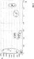
- Fig. 2 shows in a simplified block diagram form a protecting system 100 for protecting a computerized device (either mobile device or a stationary device), according to an embodiment of the present invention.
- the environment 111 is the conventional computerized environment (hardware and software) of the device.
- the DC supply 113 may be either a battery of the mobile device or a DC power supply of a stationary device and it feeds, as is conventional, DC voltage to the hardware portion of the environment 111.
- the DC supply monitoring unit 112 and the malicious events signatures database 114 are similar in their nature to the battery monitoring unit 12 and malicious events signatures 14 of Fig. 1 , respectively, however they operate on a computerized environment 150 which is totally isolated from the computerized environment 111 of the device.
- the battery monitoring unit 112 and the malicious events signatures database 114 are operated by a separate microprocessor (not shown) which is positioned on an individual printed circuit which is totally separated and isolated both physically and in terms of connectivity from both the hardware and software of the computerized environment 111 of the device.
- the DC supply 113 is shown external of the computerized environments 111 and 150, as the battery only feeds in parallel these two environments with DC voltage. However, there is no way whatsoever for interaction between these two environments 111 and 150, as they are totally separated and isolated one from the other both in terms of hardware physical separation and in terms of software separation.
- the DC supply monitoring unit 112 which is totally separated and isolated from the computerized environment of the device also comprises alert means (not shown).
- the alert may be provided to the user, visually, audibly or both.
- the visual alert may be provided to the user, for example, by means of a light emitting diode, and the audible alert may be provided by means of a buzzer.
- all the means for providing said alerts are located on the printed circuit which is totally separated and isolated from the computerized environment of the device.
- several levels of alert may be provided, and these levels may be reflected either visually of audibly.
- Fig. 3 illustrates the interconnections between the DC supply unit 112 and the two separate environments 111 and 150.
- the power consumption of the computerized environment 111 of the device can be analyzed by measuring the voltage and current of the device DC supply 113.
- the voltage of the DC supply is almost constant, so only the current provides significant data.
- Standard sampling equipment based on ADC Analog to Digital Converter
- ADC Analog to Digital Converter
- the resistor R can be connected: to the positive electrode of the DC supply or to the negative (ground) electrode.
- the resistor R is connected to the positive electrode, a differential amplifier for ADC (Analog to Digital Converter) is required.
- ADC Analog to Digital Converter
- the resistor is connected to the negative electrode of the DC supply, a single end connection can do the work.
- the first connection is preferred due to its smaller amount of interferences.
- the sampling rate has to be at least two times larger than the maximum frequency of the sampled data (based on the Nyquist rate).
- a setup according to the present invention was arranged to check a mobile phone for various activities.
- the measurement setup was based on a National InstrumentsTM ADC USB card, with differential analog inputs, with voltage range of ⁇ 10 Volt, 1.25MHz sample rate, and 16 bit ADC resolution.
- the card was connected to a PC through a USB connection, and data acquisition was performed using a LabviewTM program.
- the sampled data was represented in the frequency domain as shown in Fig. 4 .
- Most of the sampled signals were found to be pulses with a steep rise and a steep decline at the start and end of the pulse, respectively, and a nearly constant segment in between.
- the fast changes in the time domain were represented by high frequencies and the constant segment by low frequencies in the frequency domain.
- the frequency domain provides better separation between signals relating to different activities.
- the transformation from time to frequency domain was performed using FFT (Fast Fourier Transform) which separated the sampled signals to plurality of discrete frequencies in the frequency domain. Each discrete frequency is referred herein as "feature”.
- FFT Fast Fourier Transform
- Each discrete frequency is referred herein as "feature”.
- the number of the features by which the signals were examined varied depending on the sampling frequency and the time window selected. Different activities such as touch, Wi-Fi or GPS etc. were observed to have distinctive patterns over different sizes of time windows.
- the average window size for GPS and Wi-Fi was 4 seconds, and the window size for touch was between 100 to 300 mSec.
- Fig. 4 is a graph showing the f 4 vs. f 0 of several events, as detected in the experiment, together with their associated indices. The graph clearly shows that the events are distinguishable. As a result of this experiment, the distinguishing between these events in terms of power consumption enables forming of "events signatures", wherein each signature is a combination of the occurrence of one or more incidents (for example, the event no. 11 "GPS ON, Screen ON" comprises of two incidents). The results show a promising potential of the invention concept.
- the DC supply monitoring unit of the invention which is totally separated and isolated from the computerized environment of the device, also comprises alert means.
- an alert may be provided to the user, visually, audibly or both.
- the visual alert may be provided to the user, for example, by means of a light emitting diode, and the audible alert may be provided by means of a buzzer.
- all the means for providing said alerts are located on the printed circuit which is totally separated and isolated from the computerized environment of the device.
- the user may decide how to relate to the alert, and whether to take an action.
- the invention is applicable to detect various types of events, either malicious or not, and consequently the term "malicious”, wherever used herein, should be viewed to relate to both of said cases.
- the computerized environment 150 of the present invention (which typically comprises a separate microprocessor and memory) is totally isolated from the computerized environment 111 of the monitored device.
- the system of the invention is positioned on a separate printed board, which has no connection, either wire connection or wireless, with the computerized environment 111 of the device.
- the printed circuit of the invention preferably has an input output port, for example, a USB, RS232, etc. port for inputting and outputting data between elements on the printed circuit and the "external world". This port may be used, for example, to update the malicious events signatures database 114 with new signatures.
- the invention may be used in conjunction with a prior art application for detecting malicious events, i.e., an application which detects such events by monitoring power consumption from the battery of power supply, and which runs within the computerized environment 111 of the device.
- each of said environments creates its own log events, and saves it within its own environment (111 or 150), respectively. Once in a while, and offline (once in a week, once in a month, etc.), both of the saved logs may be downloaded and compared by means of a program which is external to both of said environments 111 and 150.
Landscapes
- Engineering & Computer Science (AREA)
- Theoretical Computer Science (AREA)
- Computer Security & Cryptography (AREA)
- Software Systems (AREA)
- Computer Hardware Design (AREA)
- General Engineering & Computer Science (AREA)
- Physics & Mathematics (AREA)
- General Physics & Mathematics (AREA)
- Health & Medical Sciences (AREA)
- General Health & Medical Sciences (AREA)
- Virology (AREA)
- Power Sources (AREA)
Description
- The field of the invention relates in general to methods and systems for securing computerized environments and devices. More specifically, the invention relates to a method and system for securing a computerized device by means of monitoring of its electrical power consumption.
- Computerized devices, either stationary or mobile, are valuable targets for skillful, sophisticated, and motivated offenders. Many protection techniques have been developed to protect computerized devices from malicious code. In this respect, the fast development of smart phones and tablets has exposed the users to still additional aspects of security issues compared to stationary devices. While intrusions into stationary devices generally provide data per se, smartphones include many built in sensors that can be turned on silently by a malicious code, thereby exposing valuable data and private information to the attacker.
- Modern smartphones host various gadgets and sensors, such as GPS, Wi-Fi, voice, camera, accelerometers, etc. The normal activation of such components (gadgets and sensors) normally requires manual input from the user, typically by touching the screen. However, an unauthorized intrusion which introduces a malicious code may activate one or more of said sensitive component without the user's consent. This serious vulnerability is exploited by remote hostile agents to gather sensitive information through the subverted mobile phone. For this purpose, and in similarity to stationary devices, a variety of security software has been developed and is widely used for protecting mobile devices. In this respect, it should be noted that the security model of most mobile phone operating systems discourages some typical monitoring solutions that are available for personal computers and stationary devices.
- One alternative solution for protecting a mobile phone from a malicious code is disclosed, for example, by Zefferer et. al. Zefferer proves that a malware running within the mobile phone has a unique characteristic "signature" (although he does not specifically uses the term "signature"), therefore various malwares can be detected by means of monitoring the power consumption from the battery. More specifically, Zefferer suggests monitoring of the power consumption by means of dedicated software to detect anomalies that may hint to the presence of malicious code. This solution is based on said assumption that a variety of malicious activities within the protected environment have characteristic and detectable behaviors, respectively, in terms of power consumption. More specifically, malicious activities have their own "signature". This solution in fact suggests performing a continuous monitoring of the power consumption by means of dedicated software, and detection of such "signatures". In some additional cases, and in a manner common in the field of computer security, this detection technique may be used in association with other protection techniques. However, according to all of the prior art publications, said monitoring of the device's power consumption, is performed by a program that runs within the same computerized environment that it intends to protect.
- The term "environment", or "computerized environment" relates herein to a range of hardware and software, that are in turn accessible either physically (for example, via a USB connector) or wirelessly (for example, via a WiFi network). Typically an "environment" is a close computerized range to which access is allowed only to authorized persons or programs, however, a "closed" environment may be breached by unauthorized activities, either via said physical connection or wirelessly.
- As noted, a variety of software tools have been developed to protect a computerized environment (i.e., either stationary computers or mobile devices), from malicious programs and activities. All of security software tools, no matter what measures they apply, have one characteristic in common: They all run a protection code on the device (stationary or mobile) or network of devices that they intend to protect, i.e., they run within the same environment that they intend to protect. For example, the anti-virus tool executes a program that runs within the device to scan the one or more hard discs and the device memory. The firewall, in turn, runs a program within the internal computerized environment that masks the structure of the environment from the world outside of this environment.
- This manner of operation, however, has a significant drawback. The fact that a malicious code has successfully injected to within the protected environment is in itself a proof for the vulnerability of this environment. As a result of this vulnerability, and by the same manner that the malicious code was successfully injected to within the protected environment, a same or another code may, for example, manipulate the protecting code (for example, anti-virus, or any other protecting software) to perform one of the following: (i) to stop operation; (ii) to ignore the existence of the malicious code within the protected environment; or (iii) to manipulate the code such that no report will be issued to the user with respect to the detection of the malicious code. Following this manipulation, the malicious code in fact can operate freely within the protected environment.
-
US 2008/027611 discloses an information processing electronic device capable of detecting undesired software by monitoring electric power consumption patterns. A sensor detects an amount of electric power or current consumed by the electronic device, and a threshold detector compares the detected electric power or current to a threshold value, to indicate that undesired software is present when the threshold is exceeded. The threshold detector is connected to a microprocessor which handles computing functions of the electronic device.WO2012/087685 discloses signature independent system bahaviour-based malware detection. - It is therefore an object of the present invention to provide a protecting code which is fully isolated and protected from any external manipulation.
- It is a more specific object of the invention to provide said protecting code which detects and alerts of unauthorized events, by monitoring the power consumption of the device.
- It is still another object of the invention to provide a method and system which can be applied to both stationary devices that are fed from a power supply and to mobile devices that are fed from a battery.
- Other objects and advantages of the invention will become apparent as the description proceeds.
- The invention relates to a system for protecting a computerized device from a malicious activity resulting from a malicious code, which comprises: (a) a first DC supply monitoring unit which is located within a separate computerized environment, namely an environment which is totally separated and isolated both physically and in terms of connectivity from the hardware and software of the computerized environment of the device; (b) a memory database for storing one or more signatures of known malicious events, each of said signatures describes the temporal effect of a malicious event, respectively, on the power consumption from the DC supply of the device; and (c) a microprocessor within said DC supply monitoring unit for continuously monitoring the power consumption from said DC supply of the device, comparing temporal characteristics of the power consumption with said malicious events signatures in said database, and alerting upon detection of a match, wherein said DC supply monitoring unit is at most physically connected to the DC supply of the device.
- Preferably, said first DC supply monitoring unit is positioned on a separate printed circuit, and wherein said microprocessor bases its monitoring on sampling of the current consumption from said DC supply.
- Preferably, said computerized device is a mobile device, and wherein said DC supply is the battery of the device.
- Preferably, said computerized device is a stationary device, and wherein said DC supply is the power supply of the device.
- Preferably, said malicious events are combined from the occurrence of one or more of individual incidents.
- Preferably, said alerting is provided by visual, audible, or a combination thereof of alert means that are positioned within said separated and isolated first DC supply monitoring unit.
said visual means is a light emitting diode, and said visual means is a buzzer. Preferably, the form and manner of the alert may be selected from several levels of alerts. - Preferably, the monitoring of the power consumption from the DC supply is performed by means of sampling of current consumption.
- Preferably, said first DC supply monitoring unit is positioned on a separate printed board, and wherein said separate printed board having a port for communicating input and output data to and from the first DC supply monitoring unit.
- Preferably, said port is used to update said database of one or more signatures.
- Preferably, said memory also stores a first events log.
- Preferably, the system further comprises: (a) a second DC supply monitoring program which runs within said computerized environment of the device simultaneously with said monitoring microprocessor that runs within said separate environment, and which forms a second events log; and (b) an external entity which extracts said first events log from the separate computerized environment and said second events log from the computerized environment of the device, and which compares said two logs to possibly detect mismatch of detected events, that hints to a malicious manipulation of said second DC supply monitoring unit.
- In the drawings:
-
Fig. 1 illustrates in a simplified block diagram form a prior art security system for determining events based on power consumption; -
Fig. 2 shows in a simplified block diagram form a protecting system for protecting a computerized device (either mobile device or a stationary device), according to an embodiment of the present invention; -
Fig. 3 illustrates the interconnections between a DC supply unit and two separate computerized environments, according to an embodiment of the invention; and -
Fig. 4 is a graph showing the f4 vs. f0 of several events, as detected in an experiment, together with their associated indices. - As noted above, all the security software that intends to protect a computerized environment from a malicious code runs some software from within the protected environment itself. This is also the case with Zefferer et. al (mentioned above) which suggests detection of malicious code by means of monitoring the power consumption of the mobile device by means of dedicated software. As also noted, this approach, i.e., the running of a security program from within the protected environment, has an inherent drawback, as the malicious code which has been successfully injected into the system may manipulate the security program itself, to either: (i) stop its operation; (ii) cause it to ignore the existence of the malicious code within the protected environment; or (iii) manipulate the security program such that no report will be issued to the user with respect to the detection of the malicious code.
-
Fig. 1 illustrates in a simplified block diagram form the manner by which the priorart security system 10, such as a hypothetical system based on Zefferer operates. The protectingsystem 10 based on Zefferer typically operates by means of a running application to protect a computerized environment of 11 of a mobile device. Naturally, the running application operates from within the protectedenvironment 11, i.e., by means of the microprocessor of the mobile device and from the same memory on which the operating system and all the other programs and applications run on the device. Therefore, and as noted above, this protectingsystem 10, having the form of a program, is susceptible to malicious manipulations. Thesystem 10 comprises a software-basedbattery monitoring unit 12 which monitors the power consumption frombattery 13 to detect battery consumption events. A battery consumption event may be considered as any change with respect to the power consumption from thebattery 13. Upon detection of any of such event, the battery monitoring unit records the event characteristics, and compares these characteristics against each of the malicious code signatures that are stored within the maliciouscode signatures database 14. Upon finding of any match between the recorded event and a signature within the database, the monitoring unit issues an alert. -
Fig. 2 shows in a simplified block diagram form a protectingsystem 100 for protecting a computerized device (either mobile device or a stationary device), according to an embodiment of the present invention. Theenvironment 111 is the conventional computerized environment (hardware and software) of the device. TheDC supply 113 may be either a battery of the mobile device or a DC power supply of a stationary device and it feeds, as is conventional, DC voltage to the hardware portion of theenvironment 111. The DCsupply monitoring unit 112 and the maliciousevents signatures database 114 are similar in their nature to thebattery monitoring unit 12 andmalicious events signatures 14 ofFig. 1 , respectively, however they operate on acomputerized environment 150 which is totally isolated from thecomputerized environment 111 of the device. More specifically, thebattery monitoring unit 112 and the maliciousevents signatures database 114 are operated by a separate microprocessor (not shown) which is positioned on an individual printed circuit which is totally separated and isolated both physically and in terms of connectivity from both the hardware and software of thecomputerized environment 111 of the device. TheDC supply 113 is shown external of thecomputerized environments environments - According to the present invention, the DC
supply monitoring unit 112 which is totally separated and isolated from the computerized environment of the device also comprises alert means (not shown). Upon detection of a malicious event, the alert may be provided to the user, visually, audibly or both. The visual alert may be provided to the user, for example, by means of a light emitting diode, and the audible alert may be provided by means of a buzzer. In any case, all the means for providing said alerts are located on the printed circuit which is totally separated and isolated from the computerized environment of the device. Furthermore, several levels of alert may be provided, and these levels may be reflected either visually of audibly. -
Fig. 3 illustrates the interconnections between theDC supply unit 112 and the twoseparate environments computerized environment 111 of the device can be analyzed by measuring the voltage and current of thedevice DC supply 113. In practice, the voltage of the DC supply is almost constant, so only the current provides significant data. Standard sampling equipment based on ADC (Analog to Digital Converter) can sample only voltage, so in order to measure the current a small series resistor R is connected to the DC supply output, ahead of the power socket, as shown inFig. 3 . In this arrangement, the sampled voltage is proportional to the current. There are two ways for the resistor R to be connected: to the positive electrode of the DC supply or to the negative (ground) electrode. If the resistor R is connected to the positive electrode, a differential amplifier for ADC (Analog to Digital Converter) is required. On the other hand if the resistor is connected to the negative electrode of the DC supply, a single end connection can do the work. The first connection is preferred due to its smaller amount of interferences. The sampling rate has to be at least two times larger than the maximum frequency of the sampled data (based on the Nyquist rate). - A setup according to the present invention was arranged to check a mobile phone for various activities. The measurement setup was based on a National Instruments™ ADC USB card, with differential analog inputs, with voltage range of ±10 Volt, 1.25MHz sample rate, and 16 bit ADC resolution. The card was connected to a PC through a USB connection, and data acquisition was performed using a Labview™ program. The sampled data was represented in the frequency domain as shown in
Fig. 4 . Most of the sampled signals were found to be pulses with a steep rise and a steep decline at the start and end of the pulse, respectively, and a nearly constant segment in between. The fast changes in the time domain were represented by high frequencies and the constant segment by low frequencies in the frequency domain. It has been found that the frequency domain provides better separation between signals relating to different activities. The transformation from time to frequency domain was performed using FFT (Fast Fourier Transform) which separated the sampled signals to plurality of discrete frequencies in the frequency domain. Each discrete frequency is referred herein as "feature". The number of the features by which the signals were examined varied depending on the sampling frequency and the time window selected. Different activities such as touch, Wi-Fi or GPS etc. were observed to have distinctive patterns over different sizes of time windows. The average window size for GPS and Wi-Fi was 4 seconds, and the window size for touch was between 100 to 300 mSec. - Various activities were separately recorded, and then concatenated. The various activities were represented by a single multi-valued label. The resulting dataset was visualized on 2 and 3 dimensions (i.e., frequencies), and revealed a pretty good separation between signals relating to the various activities. In addition, the dataset was classified, using J48 and LogitBoost (Machine Learning techniques well known in the art), and the resulting accuracy was found to be around 97%. Feature selection, using info-gain and gain-ratio, allowed a reduction of the number of features from 50 to 5, without a significant loss of accuracy. The following list provides index for the tested events:
# Tested activities 1 Screen OFF 2 Screen ON until shutdown 3 Touching the screen 4 GPS ON, screen OFF 7 WiFi ON 11 GPS ON, screen ON 14 GPS ON, WiFi ON -
Fig. 4 is a graph showing the f4 vs. f0 of several events, as detected in the experiment, together with their associated indices. The graph clearly shows that the events are distinguishable. As a result of this experiment, the distinguishing between these events in terms of power consumption enables forming of "events signatures", wherein each signature is a combination of the occurrence of one or more incidents (for example, the event no. 11 "GPS ON, Screen ON" comprises of two incidents). The results show a promising potential of the invention concept. - According to the present invention, the DC supply monitoring unit of the invention, which is totally separated and isolated from the computerized environment of the device, also comprises alert means. Upon detection of an event, an alert may be provided to the user, visually, audibly or both. The visual alert may be provided to the user, for example, by means of a light emitting diode, and the audible alert may be provided by means of a buzzer. In any case, all the means for providing said alerts are located on the printed circuit which is totally separated and isolated from the computerized environment of the device. Upon receipt of the alert, the user may decide how to relate to the alert, and whether to take an action.
- Furthermore, the invention is applicable to detect various types of events, either malicious or not, and consequently the term "malicious", wherever used herein, should be viewed to relate to both of said cases.
- As noted above, the
computerized environment 150 of the present invention (which typically comprises a separate microprocessor and memory) is totally isolated from thecomputerized environment 111 of the monitored device. Preferably, the system of the invention is positioned on a separate printed board, which has no connection, either wire connection or wireless, with thecomputerized environment 111 of the device. The printed circuit of the invention, however, preferably has an input output port, for example, a USB, RS232, etc. port for inputting and outputting data between elements on the printed circuit and the "external world". This port may be used, for example, to update the maliciousevents signatures database 114 with new signatures. - In still another aspect, the invention may be used in conjunction with a prior art application for detecting malicious events, i.e., an application which detects such events by monitoring power consumption from the battery of power supply, and which runs within the
computerized environment 111 of the device. According to this aspect of the invention, each of said environments creates its own log events, and saves it within its own environment (111 or 150), respectively. Once in a while, and offline (once in a week, once in a month, etc.), both of the saved logs may be downloaded and compared by means of a program which is external to both of saidenvironments computerized environment 111 of the device, this situation may hint that said monitoring program that runs withinenvironment 111 has been maliciously manipulated to hide (or not to detect) malicious events. While some embodiments of the invention have been described by way of illustration, it will be apparent that the invention can be carried into practice with many modifications, variations and adaptations, and with the use of numerous equivalents or alternative solutions that are within the scope of persons skilled in the art, without departing from the scope of the invention or exceeding the scope of the claims.
Claims (13)
- System (100) for protecting a computerized device from a malicious activity resulting from a malicious code, comprising:a. a computerized environment (111) of said computerized device having hardware and software which is accessible to a data network;b. a separate computerized environment (150) configured with hardware and software which are totally separated and isolated from the computerized environment of said computerized device in terms of hardware physical separation and in terms of software separation;c. a DC supply (113) for powering the computerized environment of said computerized device;d. a microprocessor-operated first DC supply monitoring unit (112) which is located within said separate computerized environment, wherein said first DC supply monitoring unit is physically connected to said DC supply and is configured to monitor power consumption from said DC supply; ande. a memory database (114) in which are stored one or more signatures of known malicious events, each of said signatures describes the temporal effect of one of said known malicious events on the power consumption from the DC supply of the device,wherein said first DC supply monitoring unit comprises alert means adapted to generate an alert signal provided to a user upon detection of a match between monitored temporal characteristics of the power consumption from said DC supply and one or more of the malicious event signatures stored in said database.
- System according to claim 1, wherein said microprocessor is operable to monitor the power consumption by sampling current consumption from said DC supply (113).
- System according to claim 1, wherein said computerized device is a mobile device, and wherein said DC supply (113) is a battery of the device.
- System according to claim 1, wherein said computerized device is a stationary device, and wherein said DC supply (113) is the power supply of the stationary device.
- System according to claim 1, wherein each of the stored signatures is indicative of a combination of the temporal effect relating to one of said known malicious events and of a temporal effect relating to one or more of individual incidents.
- System according to claim 1, wherein said alert means is selected from visual alert means, audible alert means, or a combination thereof.
- System according to claim 6, wherein said visual alert means is a light emitting diode, and said audible alert means is a buzzer.
- System according to claim 6, wherein the form and manner of the alert may be selected from several levels of alerts.
- System according to claim 1, wherein said first DC supply monitoring unit (112) is positioned on a printed circuit board separate from, and unconnected to, the computerized environment (111) of the computerized device, and wherein said separate printed board has a port for communicating input and output data to and from the first DC supply monitoring unit (112).
- System according to claim 9, wherein said port is used to update said memory database (114) of one or more signatures.
- System according to claim 9, wherein said memory database (114) also stores a first event log.
- System according to claim 11, which further comprises:a. a second DC supply monitoring unit which runs within said computerized environment (111) of the device simultaneously with said first DC supply monitoring unit (112) that runs within said separate environment (150), and is configured to generate a second event log which is indicative of the monitored temporal characteristics of the power consumption derived from said DC supply; andb. an external entity which extracts said first event log from the separate computerized environment and said second event log from the computerized environment of the device, and which compares said first and second event logs to detect mismatch of detected malicious events which is reflective of a malicious manipulation of said second DC supply monitoring unit.
- System according to claim 1, wherein the DC supply (113) is external of, and feeds in parallel with DC voltage, the computerized environment (111) of said computerized device and said separate computerized environment (150).
Applications Claiming Priority (2)
| Application Number | Priority Date | Filing Date | Title |
|---|---|---|---|
| US201461969179P | 2014-03-23 | 2014-03-23 | |
| PCT/IL2015/050297 WO2015145425A1 (en) | 2014-03-23 | 2015-03-22 | System and method for detecting activities within a computerized device based on monitoring of its power consumption |
Publications (3)
| Publication Number | Publication Date |
|---|---|
| EP3123273A1 EP3123273A1 (en) | 2017-02-01 |
| EP3123273A4 EP3123273A4 (en) | 2017-10-18 |
| EP3123273B1 true EP3123273B1 (en) | 2020-12-30 |
Family
ID=54194067
Family Applications (1)
| Application Number | Title | Priority Date | Filing Date |
|---|---|---|---|
| EP15767848.3A Active EP3123273B1 (en) | 2014-03-23 | 2015-03-22 | System and method for detecting activities within a computerized device based on monitoring of its power consumption |
Country Status (4)
| Country | Link |
|---|---|
| US (1) | US10817605B2 (en) |
| EP (1) | EP3123273B1 (en) |
| IL (1) | IL247807B (en) |
| WO (1) | WO2015145425A1 (en) |
Families Citing this family (6)
| Publication number | Priority date | Publication date | Assignee | Title |
|---|---|---|---|---|
| US10296740B2 (en) | 2014-05-18 | 2019-05-21 | B.G. Negev Technologies and Application Ltd., at Ben-Gurion University | System and method for detecting activities within a bootstrap of a computerized device based on monitoring of power consumption |
| US11436317B2 (en) * | 2017-02-21 | 2022-09-06 | Raptor Engineering LLC | Systems and methods for assuring integrity of operating system and software components at runtime |
| CN108874605B (en) * | 2018-06-29 | 2021-09-17 | Oppo广东移动通信有限公司 | Display screen testing method and device, electronic equipment and storage medium |
| US11354411B2 (en) | 2020-03-18 | 2022-06-07 | Robert Bosch Gmbh | Microcontroller program instruction execution fingerprinting and intrusion detection |
| EP3933629A1 (en) | 2020-07-01 | 2022-01-05 | Nokia Technologies Oy | Apparatus, method and computer program for detecting malware |
| US20220113982A1 (en) * | 2020-10-09 | 2022-04-14 | Arris Enterprises Llc | Selective switching of an active partition in an electronic device |
Citations (1)
| Publication number | Priority date | Publication date | Assignee | Title |
|---|---|---|---|---|
| WO2012087685A1 (en) * | 2010-12-23 | 2012-06-28 | Intel Corporation | Signature-independent, system behavior-based malware detection |
Family Cites Families (11)
| Publication number | Priority date | Publication date | Assignee | Title |
|---|---|---|---|---|
| US7184905B2 (en) * | 2003-09-29 | 2007-02-27 | Stefan Donald A | Method and system for monitoring power supplies |
| US7289875B2 (en) | 2003-11-14 | 2007-10-30 | Siemens Technology-To-Business Center Llc | Systems and methods for sway control |
| WO2006028558A1 (en) * | 2004-09-03 | 2006-03-16 | Virgina Tech Intellectual Properties, Inc. | Detecting software attacks by monitoring electric power consumption patterns |
| DE102006005053B4 (en) * | 2006-02-03 | 2012-10-25 | Infineon Technologies Ag | Apparatus and method for detecting an attack on an electrical circuit |
| GB2458158B (en) | 2008-03-07 | 2010-06-23 | Alertme Com Ltd | Electrical appliance monitoring systems |
| WO2010141826A2 (en) * | 2009-06-05 | 2010-12-09 | The Regents Of The University Of Michigan | System and method for detecting energy consumption anomalies and mobile malware variants |
| US20120180126A1 (en) * | 2010-07-13 | 2012-07-12 | Lei Liu | Probable Computing Attack Detector |
| US20120158201A1 (en) * | 2010-12-20 | 2012-06-21 | Openpeak Inc. | System and method for providing security based on power consumption |
| CN103198256B (en) * | 2012-01-10 | 2016-05-25 | 凹凸电子(武汉)有限公司 | For detection of detection system and the method for Application Status |
| KR101864828B1 (en) * | 2012-04-10 | 2018-06-05 | 삼성전자주식회사 | Method and apparatus for managing electornic appliance |
| US9147072B2 (en) * | 2013-10-28 | 2015-09-29 | Qualcomm Incorporated | Method and system for performing behavioral analysis operations in a mobile device based on application state |
-
2015
- 2015-03-22 WO PCT/IL2015/050297 patent/WO2015145425A1/en active Application Filing
- 2015-03-22 US US15/128,352 patent/US10817605B2/en active Active
- 2015-03-22 EP EP15767848.3A patent/EP3123273B1/en active Active
-
2016
- 2016-09-14 IL IL247807A patent/IL247807B/en active IP Right Grant
Patent Citations (1)
| Publication number | Priority date | Publication date | Assignee | Title |
|---|---|---|---|---|
| WO2012087685A1 (en) * | 2010-12-23 | 2012-06-28 | Intel Corporation | Signature-independent, system behavior-based malware detection |
Also Published As
| Publication number | Publication date |
|---|---|
| US10817605B2 (en) | 2020-10-27 |
| IL247807A0 (en) | 2016-11-30 |
| EP3123273A1 (en) | 2017-02-01 |
| US20180173877A1 (en) | 2018-06-21 |
| WO2015145425A1 (en) | 2015-10-01 |
| EP3123273A4 (en) | 2017-10-18 |
| IL247807B (en) | 2021-04-29 |
Similar Documents
| Publication | Publication Date | Title |
|---|---|---|
| EP3123273B1 (en) | System and method for detecting activities within a computerized device based on monitoring of its power consumption | |
| Clark et al. | {WattsUpDoc}: Power side channels to nonintrusively discover untargeted malware on embedded medical devices | |
| KR102160659B1 (en) | Detection of anomalous program execution using hardware-based micro-architectural data | |
| Martinelli et al. | Bridemaid: An hybrid tool for accurate detection of android malware | |
| EP2069993B1 (en) | Security system and method for detecting intrusion in a computerized system | |
| US10296740B2 (en) | System and method for detecting activities within a bootstrap of a computerized device based on monitoring of power consumption | |
| US20040250169A1 (en) | IDS log analysis support apparatus, IDS log analysis support method and IDS log analysis support program | |
| US10462170B1 (en) | Systems and methods for log and snort synchronized threat detection | |
| KR20160008509A (en) | Unsupervised anomaly-based malware detection using hardware features | |
| US10657257B2 (en) | Feature vector aggregation for malware detection | |
| KR101444308B1 (en) | System for early informing a leakage of information | |
| Chiu et al. | Frequent pattern based user behavior anomaly detection for cloud system | |
| KR101244731B1 (en) | Apparatus and method for detecting malicious shell code by using debug event | |
| US20220179954A1 (en) | Method for generating characteristic information of malware which informs attack type of the malware | |
| CN115225321A (en) | Financial data anti-theft alarm system and method based on big data | |
| US20200050802A1 (en) | Port security device for computing devices and method of operating such | |
| Clark | The security and privacy implications of energy-proportional computing | |
| Jiménez et al. | Malware detection on general-purpose computers using power consumption monitoring: A proof of concept and case study | |
| CN112261034A (en) | Network security protection system based on enterprise intranet | |
| CN107358101B (en) | Lego software detection method and system based on authority mode | |
| Dhakar et al. | A new model for intrusion detection based on reduced error pruning technique | |
| Vyas et al. | Intrusion detection systems: a modern investigation | |
| GB201317541D0 (en) | A patient monitoring system with image capture functionality | |
| CN111832030A (en) | Data security audit device and method based on domestic password data identification | |
| Davis et al. | Resident security system for government/industry owned computers |
Legal Events
| Date | Code | Title | Description |
|---|---|---|---|
| STAA | Information on the status of an ep patent application or granted ep patent |
Free format text: STATUS: THE INTERNATIONAL PUBLICATION HAS BEEN MADE |
|
| PUAI | Public reference made under article 153(3) epc to a published international application that has entered the european phase |
Free format text: ORIGINAL CODE: 0009012 |
|
| STAA | Information on the status of an ep patent application or granted ep patent |
Free format text: STATUS: REQUEST FOR EXAMINATION WAS MADE |
|
| 17P | Request for examination filed |
Effective date: 20161021 |
|
| AK | Designated contracting states |
Kind code of ref document: A1 Designated state(s): AL AT BE BG CH CY CZ DE DK EE ES FI FR GB GR HR HU IE IS IT LI LT LU LV MC MK MT NL NO PL PT RO RS SE SI SK SM TR |
|
| AX | Request for extension of the european patent |
Extension state: BA ME |
|
| DAV | Request for validation of the european patent (deleted) | ||
| DAX | Request for extension of the european patent (deleted) | ||
| A4 | Supplementary search report drawn up and despatched |
Effective date: 20170919 |
|
| RIC1 | Information provided on ipc code assigned before grant |
Ipc: G06F 1/28 20060101AFI20170913BHEP Ipc: G06F 21/81 20130101ALI20170913BHEP Ipc: G06F 21/55 20130101ALI20170913BHEP |
|
| STAA | Information on the status of an ep patent application or granted ep patent |
Free format text: STATUS: EXAMINATION IS IN PROGRESS |
|
| 17Q | First examination report despatched |
Effective date: 20190916 |
|
| GRAP | Despatch of communication of intention to grant a patent |
Free format text: ORIGINAL CODE: EPIDOSNIGR1 |
|
| STAA | Information on the status of an ep patent application or granted ep patent |
Free format text: STATUS: GRANT OF PATENT IS INTENDED |
|
| INTG | Intention to grant announced |
Effective date: 20200723 |
|
| GRAS | Grant fee paid |
Free format text: ORIGINAL CODE: EPIDOSNIGR3 |
|
| GRAA | (expected) grant |
Free format text: ORIGINAL CODE: 0009210 |
|
| STAA | Information on the status of an ep patent application or granted ep patent |
Free format text: STATUS: THE PATENT HAS BEEN GRANTED |
|
| AK | Designated contracting states |
Kind code of ref document: B1 Designated state(s): AL AT BE BG CH CY CZ DE DK EE ES FI FR GB GR HR HU IE IS IT LI LT LU LV MC MK MT NL NO PL PT RO RS SE SI SK SM TR |
|
| REG | Reference to a national code |
Ref country code: GB Ref legal event code: FG4D |
|
| REG | Reference to a national code |
Ref country code: AT Ref legal event code: REF Ref document number: 1350579 Country of ref document: AT Kind code of ref document: T Effective date: 20210115 |
|
| REG | Reference to a national code |
Ref country code: DE Ref legal event code: R096 Ref document number: 602015064155 Country of ref document: DE |
|
| REG | Reference to a national code |
Ref country code: IE Ref legal event code: FG4D |
|
| PG25 | Lapsed in a contracting state [announced via postgrant information from national office to epo] |
Ref country code: FI Free format text: LAPSE BECAUSE OF FAILURE TO SUBMIT A TRANSLATION OF THE DESCRIPTION OR TO PAY THE FEE WITHIN THE PRESCRIBED TIME-LIMIT Effective date: 20201230 Ref country code: RS Free format text: LAPSE BECAUSE OF FAILURE TO SUBMIT A TRANSLATION OF THE DESCRIPTION OR TO PAY THE FEE WITHIN THE PRESCRIBED TIME-LIMIT Effective date: 20201230 Ref country code: NO Free format text: LAPSE BECAUSE OF FAILURE TO SUBMIT A TRANSLATION OF THE DESCRIPTION OR TO PAY THE FEE WITHIN THE PRESCRIBED TIME-LIMIT Effective date: 20210330 Ref country code: GR Free format text: LAPSE BECAUSE OF FAILURE TO SUBMIT A TRANSLATION OF THE DESCRIPTION OR TO PAY THE FEE WITHIN THE PRESCRIBED TIME-LIMIT Effective date: 20210331 |
|
| REG | Reference to a national code |
Ref country code: AT Ref legal event code: MK05 Ref document number: 1350579 Country of ref document: AT Kind code of ref document: T Effective date: 20201230 |
|
| PG25 | Lapsed in a contracting state [announced via postgrant information from national office to epo] |
Ref country code: BG Free format text: LAPSE BECAUSE OF FAILURE TO SUBMIT A TRANSLATION OF THE DESCRIPTION OR TO PAY THE FEE WITHIN THE PRESCRIBED TIME-LIMIT Effective date: 20210330 Ref country code: LV Free format text: LAPSE BECAUSE OF FAILURE TO SUBMIT A TRANSLATION OF THE DESCRIPTION OR TO PAY THE FEE WITHIN THE PRESCRIBED TIME-LIMIT Effective date: 20201230 Ref country code: SE Free format text: LAPSE BECAUSE OF FAILURE TO SUBMIT A TRANSLATION OF THE DESCRIPTION OR TO PAY THE FEE WITHIN THE PRESCRIBED TIME-LIMIT Effective date: 20201230 |
|
| REG | Reference to a national code |
Ref country code: NL Ref legal event code: MP Effective date: 20201230 |
|
| PG25 | Lapsed in a contracting state [announced via postgrant information from national office to epo] |
Ref country code: HR Free format text: LAPSE BECAUSE OF FAILURE TO SUBMIT A TRANSLATION OF THE DESCRIPTION OR TO PAY THE FEE WITHIN THE PRESCRIBED TIME-LIMIT Effective date: 20201230 |
|
| REG | Reference to a national code |
Ref country code: LT Ref legal event code: MG9D |
|
| PG25 | Lapsed in a contracting state [announced via postgrant information from national office to epo] |
Ref country code: RO Free format text: LAPSE BECAUSE OF FAILURE TO SUBMIT A TRANSLATION OF THE DESCRIPTION OR TO PAY THE FEE WITHIN THE PRESCRIBED TIME-LIMIT Effective date: 20201230 Ref country code: PT Free format text: LAPSE BECAUSE OF FAILURE TO SUBMIT A TRANSLATION OF THE DESCRIPTION OR TO PAY THE FEE WITHIN THE PRESCRIBED TIME-LIMIT Effective date: 20210430 Ref country code: SK Free format text: LAPSE BECAUSE OF FAILURE TO SUBMIT A TRANSLATION OF THE DESCRIPTION OR TO PAY THE FEE WITHIN THE PRESCRIBED TIME-LIMIT Effective date: 20201230 Ref country code: LT Free format text: LAPSE BECAUSE OF FAILURE TO SUBMIT A TRANSLATION OF THE DESCRIPTION OR TO PAY THE FEE WITHIN THE PRESCRIBED TIME-LIMIT Effective date: 20201230 Ref country code: CZ Free format text: LAPSE BECAUSE OF FAILURE TO SUBMIT A TRANSLATION OF THE DESCRIPTION OR TO PAY THE FEE WITHIN THE PRESCRIBED TIME-LIMIT Effective date: 20201230 Ref country code: EE Free format text: LAPSE BECAUSE OF FAILURE TO SUBMIT A TRANSLATION OF THE DESCRIPTION OR TO PAY THE FEE WITHIN THE PRESCRIBED TIME-LIMIT Effective date: 20201230 Ref country code: NL Free format text: LAPSE BECAUSE OF FAILURE TO SUBMIT A TRANSLATION OF THE DESCRIPTION OR TO PAY THE FEE WITHIN THE PRESCRIBED TIME-LIMIT Effective date: 20201230 |
|
| PG25 | Lapsed in a contracting state [announced via postgrant information from national office to epo] |
Ref country code: PL Free format text: LAPSE BECAUSE OF FAILURE TO SUBMIT A TRANSLATION OF THE DESCRIPTION OR TO PAY THE FEE WITHIN THE PRESCRIBED TIME-LIMIT Effective date: 20201230 Ref country code: AT Free format text: LAPSE BECAUSE OF FAILURE TO SUBMIT A TRANSLATION OF THE DESCRIPTION OR TO PAY THE FEE WITHIN THE PRESCRIBED TIME-LIMIT Effective date: 20201230 |
|
| PG25 | Lapsed in a contracting state [announced via postgrant information from national office to epo] |
Ref country code: IS Free format text: LAPSE BECAUSE OF FAILURE TO SUBMIT A TRANSLATION OF THE DESCRIPTION OR TO PAY THE FEE WITHIN THE PRESCRIBED TIME-LIMIT Effective date: 20210430 |
|
| REG | Reference to a national code |
Ref country code: DE Ref legal event code: R097 Ref document number: 602015064155 Country of ref document: DE |
|
| PG25 | Lapsed in a contracting state [announced via postgrant information from national office to epo] |
Ref country code: MC Free format text: LAPSE BECAUSE OF FAILURE TO SUBMIT A TRANSLATION OF THE DESCRIPTION OR TO PAY THE FEE WITHIN THE PRESCRIBED TIME-LIMIT Effective date: 20201230 Ref country code: IT Free format text: LAPSE BECAUSE OF FAILURE TO SUBMIT A TRANSLATION OF THE DESCRIPTION OR TO PAY THE FEE WITHIN THE PRESCRIBED TIME-LIMIT Effective date: 20201230 Ref country code: AL Free format text: LAPSE BECAUSE OF FAILURE TO SUBMIT A TRANSLATION OF THE DESCRIPTION OR TO PAY THE FEE WITHIN THE PRESCRIBED TIME-LIMIT Effective date: 20201230 |
|
| REG | Reference to a national code |
Ref country code: CH Ref legal event code: PL |
|
| PLBE | No opposition filed within time limit |
Free format text: ORIGINAL CODE: 0009261 |
|
| STAA | Information on the status of an ep patent application or granted ep patent |
Free format text: STATUS: NO OPPOSITION FILED WITHIN TIME LIMIT |
|
| PG25 | Lapsed in a contracting state [announced via postgrant information from national office to epo] |
Ref country code: DK Free format text: LAPSE BECAUSE OF FAILURE TO SUBMIT A TRANSLATION OF THE DESCRIPTION OR TO PAY THE FEE WITHIN THE PRESCRIBED TIME-LIMIT Effective date: 20201230 Ref country code: ES Free format text: LAPSE BECAUSE OF FAILURE TO SUBMIT A TRANSLATION OF THE DESCRIPTION OR TO PAY THE FEE WITHIN THE PRESCRIBED TIME-LIMIT Effective date: 20201230 |
|
| 26N | No opposition filed |
Effective date: 20211001 |
|
| REG | Reference to a national code |
Ref country code: BE Ref legal event code: MM Effective date: 20210331 |
|
| PG25 | Lapsed in a contracting state [announced via postgrant information from national office to epo] |
Ref country code: IE Free format text: LAPSE BECAUSE OF NON-PAYMENT OF DUE FEES Effective date: 20210322 Ref country code: CH Free format text: LAPSE BECAUSE OF NON-PAYMENT OF DUE FEES Effective date: 20210331 Ref country code: LI Free format text: LAPSE BECAUSE OF NON-PAYMENT OF DUE FEES Effective date: 20210331 Ref country code: LU Free format text: LAPSE BECAUSE OF NON-PAYMENT OF DUE FEES Effective date: 20210322 |
|
| PG25 | Lapsed in a contracting state [announced via postgrant information from national office to epo] |
Ref country code: SI Free format text: LAPSE BECAUSE OF FAILURE TO SUBMIT A TRANSLATION OF THE DESCRIPTION OR TO PAY THE FEE WITHIN THE PRESCRIBED TIME-LIMIT Effective date: 20201230 |
|
| PG25 | Lapsed in a contracting state [announced via postgrant information from national office to epo] |
Ref country code: IS Free format text: LAPSE BECAUSE OF FAILURE TO SUBMIT A TRANSLATION OF THE DESCRIPTION OR TO PAY THE FEE WITHIN THE PRESCRIBED TIME-LIMIT Effective date: 20210430 |
|
| PG25 | Lapsed in a contracting state [announced via postgrant information from national office to epo] |
Ref country code: BE Free format text: LAPSE BECAUSE OF NON-PAYMENT OF DUE FEES Effective date: 20210331 |
|
| REG | Reference to a national code |
Ref country code: DE Ref legal event code: R082 Ref document number: 602015064155 Country of ref document: DE Representative=s name: CBDL PATENTANWAELTE GBR, DE |
|
| PG25 | Lapsed in a contracting state [announced via postgrant information from national office to epo] |
Ref country code: HU Free format text: LAPSE BECAUSE OF FAILURE TO SUBMIT A TRANSLATION OF THE DESCRIPTION OR TO PAY THE FEE WITHIN THE PRESCRIBED TIME-LIMIT; INVALID AB INITIO Effective date: 20150322 |
|
| P01 | Opt-out of the competence of the unified patent court (upc) registered |
Effective date: 20230512 |
|
| PG25 | Lapsed in a contracting state [announced via postgrant information from national office to epo] |
Ref country code: CY Free format text: LAPSE BECAUSE OF FAILURE TO SUBMIT A TRANSLATION OF THE DESCRIPTION OR TO PAY THE FEE WITHIN THE PRESCRIBED TIME-LIMIT Effective date: 20201230 |
|
| PG25 | Lapsed in a contracting state [announced via postgrant information from national office to epo] |
Ref country code: SM Free format text: LAPSE BECAUSE OF FAILURE TO SUBMIT A TRANSLATION OF THE DESCRIPTION OR TO PAY THE FEE WITHIN THE PRESCRIBED TIME-LIMIT Effective date: 20201230 |
|
| PGFP | Annual fee paid to national office [announced via postgrant information from national office to epo] |
Ref country code: FR Payment date: 20231229 Year of fee payment: 10 |
|
| PG25 | Lapsed in a contracting state [announced via postgrant information from national office to epo] |
Ref country code: MK Free format text: LAPSE BECAUSE OF FAILURE TO SUBMIT A TRANSLATION OF THE DESCRIPTION OR TO PAY THE FEE WITHIN THE PRESCRIBED TIME-LIMIT Effective date: 20201230 |
|
| PGFP | Annual fee paid to national office [announced via postgrant information from national office to epo] |
Ref country code: DE Payment date: 20231229 Year of fee payment: 10 Ref country code: GB Payment date: 20240108 Year of fee payment: 10 |