EP3123180B1 - Data decimation system and method for facilitating transmission and viewing of waveforms generated by an electrical device - Google Patents
Data decimation system and method for facilitating transmission and viewing of waveforms generated by an electrical device Download PDFInfo
- Publication number
- EP3123180B1 EP3123180B1 EP15706107.8A EP15706107A EP3123180B1 EP 3123180 B1 EP3123180 B1 EP 3123180B1 EP 15706107 A EP15706107 A EP 15706107A EP 3123180 B1 EP3123180 B1 EP 3123180B1
- Authority
- EP
- European Patent Office
- Prior art keywords
- data
- waveform data
- waveform
- decimated
- pixel resolution
- Prior art date
- Legal status (The legal status is an assumption and is not a legal conclusion. Google has not performed a legal analysis and makes no representation as to the accuracy of the status listed.)
- Active
Links
Images
Classifications
-
- G—PHYSICS
- G01—MEASURING; TESTING
- G01R—MEASURING ELECTRIC VARIABLES; MEASURING MAGNETIC VARIABLES
- G01R13/00—Arrangements for displaying electric variables or waveforms
- G01R13/02—Arrangements for displaying electric variables or waveforms for displaying measured electric variables in digital form
-
- G—PHYSICS
- G01—MEASURING; TESTING
- G01R—MEASURING ELECTRIC VARIABLES; MEASURING MAGNETIC VARIABLES
- G01R13/00—Arrangements for displaying electric variables or waveforms
- G01R13/02—Arrangements for displaying electric variables or waveforms for displaying measured electric variables in digital form
- G01R13/0218—Circuits therefor
- G01R13/0272—Circuits therefor for sampling
-
- G—PHYSICS
- G01—MEASURING; TESTING
- G01R—MEASURING ELECTRIC VARIABLES; MEASURING MAGNETIC VARIABLES
- G01R13/00—Arrangements for displaying electric variables or waveforms
- G01R13/02—Arrangements for displaying electric variables or waveforms for displaying measured electric variables in digital form
- G01R13/029—Software therefor
-
- G—PHYSICS
- G01—MEASURING; TESTING
- G01R—MEASURING ELECTRIC VARIABLES; MEASURING MAGNETIC VARIABLES
- G01R19/00—Arrangements for measuring currents or voltages or for indicating presence or sign thereof
- G01R19/25—Arrangements for measuring currents or voltages or for indicating presence or sign thereof using digital measurement techniques
- G01R19/2513—Arrangements for monitoring electric power systems, e.g. power lines or loads; Logging
Definitions
- the disclosed concept pertains generally to the monitoring of waveforms in electrical systems and, more particularly, to a data decimation technique and system for facilitating the transmission and display of waveforms, such as transient voltage spike/surge waveforms, in an electrical system.
- spikes also known as surges
- voltage spikes voltage spikes
- current spikes current spikes
- transferred energy spikes energy spikes
- Spikes can be caused by any of a number of events, such as, without limitation, lightning strikes, power outages, tripped circuit breakers, short circuits, power transitions in other large equipment on the same power line, malfunctions caused by the power company, and electromagnetic pulses (EMPs).
- EMPs electromagnetic pulses
- a spike When a spike occurs, it is important to analyze the spike in order to determine the cause and/or severity thereof. Failure to do so may lead to infrastructure damage, safety hazards, and downtime, among other issues. This is usually done by capturing a waveform representing the spike (e.g., a voltage waveform) using a metering device and analyzing that waveform at, for example, a remote location on a client device such as a PC, laptop computer, tablet or smartphone.
- a waveform representing the spike e.g., a voltage waveform
- metering devices capture the transient waveforms at a high sampling rate, resulting in a large number of data points. For example, it is not uncommon for a metering device to capture and create waveforms that constitute more than 100,000 data points in a 20 millisecond (ms) cycle time (6 MHz).
- ms millisecond
- the metering device may be able to operate at multiple cycle time, such as the cycle time just described and 1MHz, 16,666 samples per cycle, 120ms duration cycle time.
- Such large amounts of data can cause traffic and/or performance problems when attempts are made to transport the data from the metering location (using a separate server or a server embedded in the metering device) over one or more networks (such as the Internet and/or a mobile data transmission network) to the target client device and display the data at the client device.
- networks such as the Internet and/or a mobile data transmission network
- the graph would look very dense and would therefore be difficult to read.
- a number of additional traffic and/or performance and usability issues may also be present, such as, without limitation, communication problems such as software breakdown, excessive cost in the case of mobile clients, and performance issues at the client device, such as excessive time required to plot data and/or to zoom in/out and pan. Attention is drawn to the software LabVIEW of National Instruments, Austin, Texas, USA, which is inter alia used to manage data for displaying the same, where the number of data points is beyond the capabilities a respective display. In order to allow displaying the data, LabVIEW provides for automatic data decimation.
- a computer program product comprising a non-transitory computer usable medium having a computer readable program code embodied therein is provided wherein the computer readable program code is adapted to be executed to implement a method of providing data as just described above.
- number shall mean one or an integer greater than one ( i.e. , a plurality).
- a component can be, but is not limited to being, a process running on a processor, a processor, an object, an executable, a thread of execution, a program, and/or a computer.
- an application running on a server and the server can be a component.
- One or more components can reside within a process and/or thread of execution, and a component can be localized on one computer and/or distributed between two or more computers.
- pixel resolution shall mean the number of pixel columns of a display of a client device.
- a client device such as a laptop, having a display resolution of 1280 ⁇ 1024, will have a pixel resolution of 1280 since it has 1280 pixel columns.
- FIG. 1 is a schematic diagram of a system 2 for facilitating the transmission and display of waveforms, such as voltage spike/surge waveforms, in an electrical system according to an exemplary embodiment of the disclosed concept.
- System 2 includes an electrical device 4, such as, without limitation, motor systems, transformers and power converters.
- System 2 also includes a power metering device 6 that is operatively coupled to electrical device 4.
- Power metering device 6 is structured to monitor the function of electrical device 4 and capture and generate waveform data by sampling one or more outputs of electric device 4.
- Such waveform data may be, for example and without limitation, data representing spikes (e.g., voltage spikes, current spikes, or energy spikes) generated by electrical device 4 in response to an event such as a lightning strike, power outage, tripped circuit breakers, or power company malfunction.
- power metering device 6 is structured to capture and generate waveform data according to one or more certain waveform cycles (e.g., 6 Hz) each having a certain waveform cycle time (e.g., 20 milliseconds (ms)) and sampling rate (e.g., 120,000 samples (i.e., data points) per waveform cycle time).
- Suitable examples of power metering device 6 inclded the Power Xpert Meter 2000/4000/6000/8000, the IQ Analyzer meter, the Digitrip series meters, and the FP5000 protective relay sold by Eaton Corporation, the assignee of the present invention.
- System 2 further includes a server component 8, which may be embedded in power metering device 6 or be separate from and operatively coupled to power metering device 6.
- Server component 8 is operatively coupled to a network 10.
- Network 10 may be one or more wired and/or wireless communications networks alone or in various combinations, and may include, without limitation, the Internet.
- system 2 includes a client device 12 that is operatively coupled to network 10.
- Client device 12 may be, for example and without limitation, a PC, laptop computer, tablet computer, smartphone, or another suitable computing device.
- client device 12 includes a display 14 (e.g., an LCD) having a certain pixel resolution (e.g., 1280).
- System 2 is structured and configured to facilitate the transmission and display of waveforms, such as transient voltage spike/surge waveforms, generated in response to events occurring in/at electrical device 4. More specifically, and as described in detail below ( FIG. 2 ), system 2 is structured and configured to facilitate the transmission and display of waveforms by reducing the amount of data that is transmitted to and used by electrical device 12 for purposes of generating and displaying waveform outputs. System 2 does so by using an interval based data decimation technique to reduce the transmitted data that employs the following three data inputs: (i) the total number of data points generated by power metering device 4 during each waveform cycle, (ii) the pixel resolution of client device 12, and (iii) the waveform cycle time of power metering device 4.
- waveforms such as transient voltage spike/surge waveforms
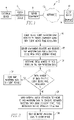
- FIG. 2 is a flowchart showing a method of operation of system 2 according to the exemplary embodiment of the present invention.
- the method begins at step 16, wherein client device 12 sends a request to server component 8 through network 10 for server component 8 to send it waveform data as measured by power metering device 6 (a "waveform data request"). Also at step 16, client device 12 sends information to server component 8 that specifies the pixel resolution of client device 12.
- server component 8 requests and receives raw waveform data for the current waveform cycle from power metering device 6.
- That raw waveform data will include all of the data points that were sampled by power metering device 8 in the waveform cycle (e.g., 120,000 data pints in a 20 ms cycle).
- server component 8 determines the total number of data points in the raw waveform data.
- step 22 a determination is made as to whether the total number of data points in the raw waveform data is less than or equal to the pixel resolution of client device 12. If the answer at step 22 is yes, then that means that the raw waveform data can be plotted by client device 12 without significant issues. As a result, the method would proceed to step 24, wherein the raw waveform data is sent to client device 12 so that the data can be used to create a display of the waveform data on display 14. If, however, the answer at step 22 is no, then that means that the total number of data points in the raw waveform data is greater than the pixel resolution of client device 12. In such a situation, the raw waveform data cannot be plotted by client device 12 without significant issues.
- the raw waveform data is decimated before being sent to client device 12 so that it can be plotted by client device 12 without causing significant issues. More specifically, at step 26, an interval based decimation technique is applied to the raw waveform data to generate decimated waveform data using both (i) the pixel resolution of client device 12, and (ii) the waveform cycle time of power metering device 4. Then, at step 28, the decimated waveform data is sent to client device 12 so that that data can be used to create a display of the waveform data on display 14. Step 26 is accomplished by performing the following steps.
- decimation interval (ms) 1/points in one millisecond value.
- a max-min decimation technique is used wherein the maximum and minimum values in each decimation interval are used to provide the decimation (i.e., they are kept with other values being discarded).
- points in one millisecond value pixel resolution of client device/(waveform cycle time (in ms) ⁇ 2).
- the points in one millisecond value will be 32 and the decimation interval will be 0.03125 ms.
- the max-min decimation technique that is employed may be customized by adding and Average (mean) point (in which case three values per interval would be utilized and the multiplier value above becomes 3) or by adding multiple max and min points
- the selection of points i.e. decimation technique
- the selection of points can be customized according to the requirements of any particular application.
- the decimated waveform data is created by, for each successive decimation interval of the raw waveform data from time zero and to the waveform cycle time (e.g., 0 to 20 ms), querying all data points in the subject decimation interval and determining and storing the maximum data point value in the interval, the minimum data point in the interval, and the corresponding times of these two (max and min) data points.
- the waveform cycle time e.g. 0 to 20 ms
- the disclosed concept provides a data decimation technique and system for facilitating the transmission and display of waveforms, such as transient voltage spike/surge waveforms, in an electrical system that overcomes traffic and/or performance problems that are present in many prior art approaches.
- waveforms such as transient voltage spike/surge waveforms
- the disclosed concept work with not only transient waveforms where the number of raw data points is more than client pixel resolution, but also on standard waveforms where the number of raw data points is more than client pixel resolution.
Landscapes
- Physics & Mathematics (AREA)
- General Physics & Mathematics (AREA)
- Remote Monitoring And Control Of Power-Distribution Networks (AREA)
- Arrangements For Transmission Of Measured Signals (AREA)
- Controls And Circuits For Display Device (AREA)
Description
- The disclosed concept pertains generally to the monitoring of waveforms in electrical systems and, more particularly, to a data decimation technique and system for facilitating the transmission and display of waveforms, such as transient voltage spike/surge waveforms, in an electrical system.
- In the context of electrical systems, spikes, also known as surges, are fast, short duration electrical transients in voltage (voltage spikes), current (current spikes), or transferred energy (energy spikes) in an electrical circuit. Spikes can be caused by any of a number of events, such as, without limitation, lightning strikes, power outages, tripped circuit breakers, short circuits, power transitions in other large equipment on the same power line, malfunctions caused by the power company, and electromagnetic pulses (EMPs).
- When a spike occurs, it is important to analyze the spike in order to determine the cause and/or severity thereof. Failure to do so may lead to infrastructure damage, safety hazards, and downtime, among other issues. This is usually done by capturing a waveform representing the spike (e.g., a voltage waveform) using a metering device and analyzing that waveform at, for example, a remote location on a client device such as a PC, laptop computer, tablet or smartphone.
- However, many metering devices capture the transient waveforms at a high sampling rate, resulting in a large number of data points. For example, it is not uncommon for a metering device to capture and create waveforms that constitute more than 100,000 data points in a 20 millisecond (ms) cycle time (6 MHz). In addition, the metering device may be able to operate at multiple cycle time, such as the cycle time just described and 1MHz, 16,666 samples per cycle, 120ms duration cycle time. Such large amounts of data can cause traffic and/or performance problems when attempts are made to transport the data from the metering location (using a separate server or a server embedded in the metering device) over one or more networks (such as the Internet and/or a mobile data transmission network) to the target client device and display the data at the client device. For example, consider a metering device that captures and creates waveform data having 134,600 points in a 20 millisecond cycles time. If a client device having a pixel resolution of only 1920 were to try to display these point as is (i.e. without reducing them), the graph would look very dense and would therefore be difficult to read. A number of additional traffic and/or performance and usability issues may also be present, such as, without limitation, communication problems such as software breakdown, excessive cost in the case of mobile clients, and performance issues at the client device, such as excessive time required to plot data and/or to zoom in/out and pan. Attention is drawn to the software LabVIEW of National Instruments, Austin, Texas, USA, which is inter alia used to manage data for displaying the same, where the number of data points is beyond the capabilities a respective display. In order to allow displaying the data, LabVIEW provides for automatic data decimation.
- Attention is also drawn to patent publication
US2011/199285 , which involves compressing a large collection of measurement data while keeping all the major features of the waveform for subsequent plotting. The collection and processing of data is initiated by a triggering event. The decimation interval is computed using the total sampling time and the number of pixel columns in the plot, corrected with the time offset between the triggering event and the first sample. - In accordance with the present invention, a method and a system as set forth in claims 1 and 4, respectively are provided. Further embodiments are inter alia disclosed in the dependent claims.
- In another embodiment, a computer program product comprising a non-transitory computer usable medium having a computer readable program code embodied therein is provided wherein the computer readable program code is adapted to be executed to implement a method of providing data as just described above.
- A full understanding of the disclosed concept can be gained from the following description of the preferred embodiments when read in conjunction with the accompanying drawings in which:
-
FIG. 1 is a schematic diagram of a system for facilitating the transmission and display of waveforms, such as voltage spike/surge waveforms, in an electrical system according to an exemplary embodiment of the disclosed concept; and -
FIG. 2 is a flowchart showing a method of operation of the system ofFIG. 1 according to the exemplary embodiment of the present invention. - Directional phrases used herein, such as, for example, left, right, front, back, top, bottom and derivatives thereof, relate to the orientation of the elements shown in the drawings and are not limiting upon the claims unless expressly recited therein.
- As employed herein, the term "number" shall mean one or an integer greater than one (i.e., a plurality).
- As employed herein, the statement that two or more parts are "coupled" together shall mean that the parts are joined together either directly or joined through one or more intermediate parts.
- As employed herein, the terms "component" and "system" are intended to refer to a computer related entity, either hardware, a combination of hardware and software, software, or software in execution. For example, a component can be, but is not limited to being, a process running on a processor, a processor, an object, an executable, a thread of execution, a program, and/or a computer. By way of illustration, both an application running on a server and the server can be a component. One or more components can reside within a process and/or thread of execution, and a component can be localized on one computer and/or distributed between two or more computers.
- As employed herein, the term "pixel resolution" shall mean the number of pixel columns of a display of a client device. For example, and without limitation, a client device, such as a laptop, having a display resolution of 1280 × 1024, will have a pixel resolution of 1280 since it has 1280 pixel columns.
-
FIG. 1 is a schematic diagram of a system 2 for facilitating the transmission and display of waveforms, such as voltage spike/surge waveforms, in an electrical system according to an exemplary embodiment of the disclosed concept. System 2 includes an electrical device 4, such as, without limitation, motor systems, transformers and power converters. System 2 also includes apower metering device 6 that is operatively coupled to electrical device 4.Power metering device 6 is structured to monitor the function of electrical device 4 and capture and generate waveform data by sampling one or more outputs of electric device 4. Such waveform data may be, for example and without limitation, data representing spikes (e.g., voltage spikes, current spikes, or energy spikes) generated by electrical device 4 in response to an event such as a lightning strike, power outage, tripped circuit breakers, or power company malfunction. According to an aspect of the disclosed concept,power metering device 6 is structured to capture and generate waveform data according to one or more certain waveform cycles (e.g., 6 Hz) each having a certain waveform cycle time (e.g., 20 milliseconds (ms)) and sampling rate (e.g., 120,000 samples (i.e., data points) per waveform cycle time). Suitable examples ofpower metering device 6 inclded the Power Xpert Meter 2000/4000/6000/8000, the IQ Analyzer meter, the Digitrip series meters, and the FP5000 protective relay sold by Eaton Corporation, the assignee of the present invention. - System 2 further includes a server component 8, which may be embedded in
power metering device 6 or be separate from and operatively coupled topower metering device 6. Server component 8 is operatively coupled to anetwork 10.Network 10 may be one or more wired and/or wireless communications networks alone or in various combinations, and may include, without limitation, the Internet. Finally, system 2 includes aclient device 12 that is operatively coupled tonetwork 10.Client device 12 may be, for example and without limitation, a PC, laptop computer, tablet computer, smartphone, or another suitable computing device. According to an aspect of the disclosed concept,client device 12 includes a display 14 (e.g., an LCD) having a certain pixel resolution (e.g., 1280). - System 2 is structured and configured to facilitate the transmission and display of waveforms, such as transient voltage spike/surge waveforms, generated in response to events occurring in/at electrical device 4. More specifically, and as described in detail below (
FIG. 2 ), system 2 is structured and configured to facilitate the transmission and display of waveforms by reducing the amount of data that is transmitted to and used byelectrical device 12 for purposes of generating and displaying waveform outputs. System 2 does so by using an interval based data decimation technique to reduce the transmitted data that employs the following three data inputs: (i) the total number of data points generated by power metering device 4 during each waveform cycle, (ii) the pixel resolution ofclient device 12, and (iii) the waveform cycle time of power metering device 4. -
FIG. 2 is a flowchart showing a method of operation of system 2 according to the exemplary embodiment of the present invention. The method begins atstep 16, whereinclient device 12 sends a request to server component 8 throughnetwork 10 for server component 8 to send it waveform data as measured by power metering device 6 (a "waveform data request"). Also atstep 16,client device 12 sends information to server component 8 that specifies the pixel resolution ofclient device 12. Next, atstep 18, and in response to the waveform data request, server component 8 requests and receives raw waveform data for the current waveform cycle frompower metering device 6. That raw waveform data will include all of the data points that were sampled by power metering device 8 in the waveform cycle (e.g., 120,000 data pints in a 20 ms cycle). Atstep 20, server component 8 determines the total number of data points in the raw waveform data. - Next, at
step 22, a determination is made as to whether the total number of data points in the raw waveform data is less than or equal to the pixel resolution ofclient device 12. If the answer atstep 22 is yes, then that means that the raw waveform data can be plotted byclient device 12 without significant issues. As a result, the method would proceed tostep 24, wherein the raw waveform data is sent toclient device 12 so that the data can be used to create a display of the waveform data ondisplay 14. If, however, the answer atstep 22 is no, then that means that the total number of data points in the raw waveform data is greater than the pixel resolution ofclient device 12. In such a situation, the raw waveform data cannot be plotted byclient device 12 without significant issues. Thus, according to the disclosed concept, in such a situation, the raw waveform data is decimated before being sent toclient device 12 so that it can be plotted byclient device 12 without causing significant issues. More specifically, atstep 26, an interval based decimation technique is applied to the raw waveform data to generate decimated waveform data using both (i) the pixel resolution ofclient device 12, and (ii) the waveform cycle time of power metering device 4. Then, at step 28, the decimated waveform data is sent toclient device 12 so that that data can be used to create a display of the waveform data ondisplay 14.Step 26 is accomplished by performing the following steps. First, a decimation interval is determined by calculating a "points in one millisecond value" according to the following formula: points in one millisecond value = pixel resolution of client device/(waveform cycle time (in ms) ∗ number of decimated data points to be generated for each decimation interval); and then calculating the decimation interval according to the following formula: decimation interval (ms) = 1/points in one millisecond value. In the exemplary embodiment, a max-min decimation technique is used wherein the maximum and minimum values in each decimation interval are used to provide the decimation (i.e., they are kept with other values being discarded). In the claimed invention, points in one millisecond value = pixel resolution of client device/(waveform cycle time (in ms) ∗ 2). For example, if the pixel resolution ofclient device 12 is 1280 and the waveform cycle time ofpower metering device 6 is 20 ms, the points in one millisecond value will be 32 and the decimation interval will be 0.03125 ms. In an alternative that is not claimed, the max-min decimation technique that is employed may be customized by adding and Average (mean) point (in which case three values per interval would be utilized and the multiplier value above becomes 3) or by adding multiple max and min points Thus, in the decimation process, the selection of points (i.e. decimation technique) can be customized according to the requirements of any particular application. After the decimation interval is determined, the decimated waveform data is created by, for each successive decimation interval of the raw waveform data from time zero and to the waveform cycle time (e.g., 0 to 20 ms), querying all data points in the subject decimation interval and determining and storing the maximum data point value in the interval, the minimum data point in the interval, and the corresponding times of these two (max and min) data points. - Thus, the disclosed concept provides a data decimation technique and system for facilitating the transmission and display of waveforms, such as transient voltage spike/surge waveforms, in an electrical system that overcomes traffic and/or performance problems that are present in many prior art approaches. The disclosed concept work with not only transient waveforms where the number of raw data points is more than client pixel resolution, but also on standard waveforms where the number of raw data points is more than client pixel resolution.
- While specific embodiments of the disclosed concept have been described in detail, it will be appreciated by those skilled in the art that various modifications and alternatives to those details could be developed in light of the overall teachings of the disclosure. Accordingly, the particular arrangements disclosed are meant to be illustrative only and not limiting as to the scope of the disclosed concept which is to be given the full breadth of the claims appended.
Claims (7)
- A method of providing data relating to an electrical device (4) to a client device (12) having a pixel resolution, comprising:receiving raw waveform data generated by a metering device (6) in response to an event related to operation of the electrical device (4), the raw waveform data having a total number of data points and a waveform cycle time associated therewith;determining whether the raw waveform data should be decimated based on the total number of data points and the pixel resolution;responsive to determining that the raw waveform data should be decimated, determining a decimation interval using the pixel resolution and the waveform cycle time using the following formula: 1/(the pixel resolution/(the waveform cycle time * 2)), and generating decimated waveform data from the raw waveform data by, for each successive decimation interval of the raw waveform data from time zero and to the waveform cycle time, querying all data points in the subject decimation interval and determining and storing the maximum data point value in the interval, the minimum data point in the interval, and the corresponding times of these maximum and minimum data points; andsending the decimated waveform data to the client device (12).
- The method according to claim 1, wherein the determining whether the raw waveform data should be decimated comprises determining whether the total number of data points is less than or equal to the pixel resolution and determining that the raw waveform data should be decimated only if the total number of data points is not less than or equal to the pixel resolution.
- The method according to claim 1, wherein the raw waveform data represents a voltage waveform generated in response to a voltage spike related to operation of the electrical device (4).
- A system (2) for providing data relating to an electrical device (4) to a client device (12) having a pixel resolution, comprising:a metering component (6) structured to generate raw waveform data generated in response to an event related to operation of the electrical device (4), the raw waveform data having a total number of data points and a waveform cycle time associated therewith;a server component (8) structured to:receive the raw waveform data;determine whether the raw waveform data should be decimated based on the total number of data points and the pixel resolution;responsive to determining that the raw waveform data should be decimated, determining a decimation interval using the pixel resolution and the waveform cycle time using the following formula: 1/(the pixel resolution/(the waveform cycle time * 2)), and generating decimatedwaveform data from the raw waveform data by, for each successive decimation interval of the raw waveform data from time zero and to the waveform cycle time, querying all data points in the subject decimation interval and determining and storing the maximum data point value in the interval, the minimum data point in the interval, and the corresponding times of these maximum and minimum data points; andsend the decimated waveform data to the client device (12) through a network (10).
- The system (2) according to claim 4, wherein the server component (8) is structured to determine whether the raw waveform data should be decimated by determining whether the total number of data points is less than or equal to the pixel resolution and determining that the raw waveform data should be decimated only if the total number of data points is not less than or equal to the pixel resolution.
- The system according to claim 4, wherein the raw waveform data represents a voltage waveform generated in response to a voltage spike related to operation of the electrical device (4).
- A computer program product, comprising a non-transitory computer usable medium having a computer readable program code embodied therein, the computer readable program code being adapted to be executed to implement a method of providing data as recited in claim 1.
Applications Claiming Priority (2)
| Application Number | Priority Date | Filing Date | Title |
|---|---|---|---|
| US14/224,689 US10119996B2 (en) | 2014-03-25 | 2014-03-25 | Data decimation system and method for facilitating transmission and viewing of waveforms generated by an electrical device |
| PCT/US2015/014950 WO2015147996A1 (en) | 2014-03-25 | 2015-02-09 | Data decimation system and method for facilitating transmission and viewing of waveforms generated by an electrical device |
Publications (2)
| Publication Number | Publication Date |
|---|---|
| EP3123180A1 EP3123180A1 (en) | 2017-02-01 |
| EP3123180B1 true EP3123180B1 (en) | 2022-03-30 |
Family
ID=52574443
Family Applications (1)
| Application Number | Title | Priority Date | Filing Date |
|---|---|---|---|
| EP15706107.8A Active EP3123180B1 (en) | 2014-03-25 | 2015-02-09 | Data decimation system and method for facilitating transmission and viewing of waveforms generated by an electrical device |
Country Status (4)
| Country | Link |
|---|---|
| US (1) | US10119996B2 (en) |
| EP (1) | EP3123180B1 (en) |
| ES (1) | ES2913980T3 (en) |
| WO (1) | WO2015147996A1 (en) |
Families Citing this family (3)
| Publication number | Priority date | Publication date | Assignee | Title |
|---|---|---|---|---|
| CN110246204B (en) * | 2019-05-28 | 2024-01-05 | 深圳数联天下智能科技有限公司 | Waveform drawing method, device, computer equipment and readable storage medium |
| CN110646650A (en) * | 2019-09-26 | 2020-01-03 | 浙江榆阳电子有限公司 | Spark generator |
| US12248008B2 (en) * | 2022-09-22 | 2025-03-11 | Rohde & Schwarz Gmbh & Co. Kg | Method, signal processing device, and measurement application device |
Citations (2)
| Publication number | Priority date | Publication date | Assignee | Title |
|---|---|---|---|---|
| EP1837665A2 (en) * | 2006-03-20 | 2007-09-26 | Tektronix, Inc. | Waveform compression and display |
| US20110199285A1 (en) * | 2010-02-18 | 2011-08-18 | Alexander Kantorov | Method and apparatus for waveform compression and display |
Family Cites Families (5)
| Publication number | Priority date | Publication date | Assignee | Title |
|---|---|---|---|---|
| US6057793A (en) | 1998-06-12 | 2000-05-02 | Oak Technology, Inc. | Digital decimation filter and method for achieving fractional data rate reduction with minimal hardware or software overhead |
| US6433726B1 (en) | 2001-06-22 | 2002-08-13 | Koninklijke Philips Electronics N.V. | Fractional decimation filter using oversampled data |
| US7755641B2 (en) | 2002-08-13 | 2010-07-13 | Broadcom Corporation | Method and system for decimating an indexed set of data elements |
| DE102010046437A1 (en) * | 2010-06-23 | 2011-12-29 | Rohde & Schwarz Gmbh & Co. Kg | Measuring device and method for decimation of a data stream |
| DE102011075669A1 (en) * | 2011-05-11 | 2012-11-15 | Rohde & Schwarz Gmbh & Co. Kg | Signal analysis in time and frequency |
-
2014
- 2014-03-25 US US14/224,689 patent/US10119996B2/en active Active
-
2015
- 2015-02-09 ES ES15706107T patent/ES2913980T3/en active Active
- 2015-02-09 EP EP15706107.8A patent/EP3123180B1/en active Active
- 2015-02-09 WO PCT/US2015/014950 patent/WO2015147996A1/en not_active Ceased
Patent Citations (2)
| Publication number | Priority date | Publication date | Assignee | Title |
|---|---|---|---|---|
| EP1837665A2 (en) * | 2006-03-20 | 2007-09-26 | Tektronix, Inc. | Waveform compression and display |
| US20110199285A1 (en) * | 2010-02-18 | 2011-08-18 | Alexander Kantorov | Method and apparatus for waveform compression and display |
Also Published As
| Publication number | Publication date |
|---|---|
| WO2015147996A1 (en) | 2015-10-01 |
| ES2913980T3 (en) | 2022-06-07 |
| US10119996B2 (en) | 2018-11-06 |
| US20150276813A1 (en) | 2015-10-01 |
| EP3123180A1 (en) | 2017-02-01 |
Similar Documents
| Publication | Publication Date | Title |
|---|---|---|
| US9435835B2 (en) | Validation of electric power system monitoring systems | |
| CN105092999B (en) | Power Quality Event Location Using Multiple Indications | |
| US7672812B2 (en) | Cable fault detection | |
| US20200112434A1 (en) | Integration of power system data onto a distributed ledger | |
| US10979330B2 (en) | Communication of electric power system samples without external time reference | |
| EP3084906A1 (en) | Remote diagnostic system and method for circuit protection devices such as miniature circuit breakers | |
| EP3024104B1 (en) | Capture of power quality information at the time a device fails | |
| AU2014216126A1 (en) | Detection of poorly damped oscillation modes | |
| US20160054364A1 (en) | Power monitoring system for a power system, and power monitoring device thereof | |
| US10119996B2 (en) | Data decimation system and method for facilitating transmission and viewing of waveforms generated by an electrical device | |
| US10114051B2 (en) | Monitoring device, monitoring system, monitoring method, and non-transitory storage medium | |
| CN111949718A (en) | Data anomaly analysis method based on cloud computing | |
| JP5618758B2 (en) | Method and system for monitoring short-circuit capacity of power system | |
| CN114778950A (en) | Pole tower grounding resistance state determination method, device, equipment and storage medium | |
| EP2934028A1 (en) | Abnormal billing processing method and system | |
| US20220206482A1 (en) | Substation equipment monitoring using a scada system | |
| US8000933B1 (en) | Method and apparatus for showing data representative of the accuracy of operations of a high-voltage switchgear | |
| KR101309400B1 (en) | Merging unit with frequency protection function | |
| CN116819311B (en) | Fault detection method and device for excitation system de-excitation loop jumper | |
| CN108037384B (en) | On-site monitoring method and device for electric power facilities | |
| KR102053167B1 (en) | apparatus for monitoring circuit-breaker of Gas insulated switchgear and Method for the same | |
| CN204615513U (en) | Grid operating monitoring intelligent management device | |
| CN104360120B (en) | Real-time waveform display method with low communication bandwidth requirement | |
| CN116087708A (en) | Device, method and equipment for determining number of discharge points based on discharge pulse signals | |
| KR102302915B1 (en) | Load shedding apparatus using voltage stability index |
Legal Events
| Date | Code | Title | Description |
|---|---|---|---|
| PUAI | Public reference made under article 153(3) epc to a published international application that has entered the european phase |
Free format text: ORIGINAL CODE: 0009012 |
|
| STAA | Information on the status of an ep patent application or granted ep patent |
Free format text: STATUS: REQUEST FOR EXAMINATION WAS MADE |
|
| 17P | Request for examination filed |
Effective date: 20160921 |
|
| AK | Designated contracting states |
Kind code of ref document: A1 Designated state(s): AL AT BE BG CH CY CZ DE DK EE ES FI FR GB GR HR HU IE IS IT LI LT LU LV MC MK MT NL NO PL PT RO RS SE SI SK SM TR |
|
| AX | Request for extension of the european patent |
Extension state: BA ME |
|
| DAX | Request for extension of the european patent (deleted) | ||
| STAA | Information on the status of an ep patent application or granted ep patent |
Free format text: STATUS: EXAMINATION IS IN PROGRESS |
|
| 17Q | First examination report despatched |
Effective date: 20200310 |
|
| RAP1 | Party data changed (applicant data changed or rights of an application transferred) |
Owner name: EATON INTELLIGENT POWER LIMITED |
|
| GRAP | Despatch of communication of intention to grant a patent |
Free format text: ORIGINAL CODE: EPIDOSNIGR1 |
|
| STAA | Information on the status of an ep patent application or granted ep patent |
Free format text: STATUS: GRANT OF PATENT IS INTENDED |
|
| INTG | Intention to grant announced |
Effective date: 20210920 |
|
| GRAS | Grant fee paid |
Free format text: ORIGINAL CODE: EPIDOSNIGR3 |
|
| GRAA | (expected) grant |
Free format text: ORIGINAL CODE: 0009210 |
|
| STAA | Information on the status of an ep patent application or granted ep patent |
Free format text: STATUS: THE PATENT HAS BEEN GRANTED |
|
| AK | Designated contracting states |
Kind code of ref document: B1 Designated state(s): AL AT BE BG CH CY CZ DE DK EE ES FI FR GB GR HR HU IE IS IT LI LT LU LV MC MK MT NL NO PL PT RO RS SE SI SK SM TR |
|
| REG | Reference to a national code |
Ref country code: GB Ref legal event code: FG4D |
|
| REG | Reference to a national code |
Ref country code: CH Ref legal event code: EP |
|
| REG | Reference to a national code |
Ref country code: AT Ref legal event code: REF Ref document number: 1479677 Country of ref document: AT Kind code of ref document: T Effective date: 20220415 |
|
| REG | Reference to a national code |
Ref country code: DE Ref legal event code: R096 Ref document number: 602015077839 Country of ref document: DE |
|
| REG | Reference to a national code |
Ref country code: IE Ref legal event code: FG4D |
|
| REG | Reference to a national code |
Ref country code: ES Ref legal event code: FG2A Ref document number: 2913980 Country of ref document: ES Kind code of ref document: T3 Effective date: 20220607 |
|
| REG | Reference to a national code |
Ref country code: LT Ref legal event code: MG9D |
|
| PG25 | Lapsed in a contracting state [announced via postgrant information from national office to epo] |
Ref country code: SE Free format text: LAPSE BECAUSE OF FAILURE TO SUBMIT A TRANSLATION OF THE DESCRIPTION OR TO PAY THE FEE WITHIN THE PRESCRIBED TIME-LIMIT Effective date: 20220330 Ref country code: RS Free format text: LAPSE BECAUSE OF FAILURE TO SUBMIT A TRANSLATION OF THE DESCRIPTION OR TO PAY THE FEE WITHIN THE PRESCRIBED TIME-LIMIT Effective date: 20220330 Ref country code: NO Free format text: LAPSE BECAUSE OF FAILURE TO SUBMIT A TRANSLATION OF THE DESCRIPTION OR TO PAY THE FEE WITHIN THE PRESCRIBED TIME-LIMIT Effective date: 20220630 Ref country code: LT Free format text: LAPSE BECAUSE OF FAILURE TO SUBMIT A TRANSLATION OF THE DESCRIPTION OR TO PAY THE FEE WITHIN THE PRESCRIBED TIME-LIMIT Effective date: 20220330 Ref country code: HR Free format text: LAPSE BECAUSE OF FAILURE TO SUBMIT A TRANSLATION OF THE DESCRIPTION OR TO PAY THE FEE WITHIN THE PRESCRIBED TIME-LIMIT Effective date: 20220330 Ref country code: BG Free format text: LAPSE BECAUSE OF FAILURE TO SUBMIT A TRANSLATION OF THE DESCRIPTION OR TO PAY THE FEE WITHIN THE PRESCRIBED TIME-LIMIT Effective date: 20220630 |
|
| REG | Reference to a national code |
Ref country code: NL Ref legal event code: MP Effective date: 20220330 |
|
| REG | Reference to a national code |
Ref country code: AT Ref legal event code: MK05 Ref document number: 1479677 Country of ref document: AT Kind code of ref document: T Effective date: 20220330 |
|
| PG25 | Lapsed in a contracting state [announced via postgrant information from national office to epo] |
Ref country code: LV Free format text: LAPSE BECAUSE OF FAILURE TO SUBMIT A TRANSLATION OF THE DESCRIPTION OR TO PAY THE FEE WITHIN THE PRESCRIBED TIME-LIMIT Effective date: 20220330 Ref country code: GR Free format text: LAPSE BECAUSE OF FAILURE TO SUBMIT A TRANSLATION OF THE DESCRIPTION OR TO PAY THE FEE WITHIN THE PRESCRIBED TIME-LIMIT Effective date: 20220701 Ref country code: FI Free format text: LAPSE BECAUSE OF FAILURE TO SUBMIT A TRANSLATION OF THE DESCRIPTION OR TO PAY THE FEE WITHIN THE PRESCRIBED TIME-LIMIT Effective date: 20220330 |
|
| PG25 | Lapsed in a contracting state [announced via postgrant information from national office to epo] |
Ref country code: NL Free format text: LAPSE BECAUSE OF FAILURE TO SUBMIT A TRANSLATION OF THE DESCRIPTION OR TO PAY THE FEE WITHIN THE PRESCRIBED TIME-LIMIT Effective date: 20220330 |
|
| PG25 | Lapsed in a contracting state [announced via postgrant information from national office to epo] |
Ref country code: SM Free format text: LAPSE BECAUSE OF FAILURE TO SUBMIT A TRANSLATION OF THE DESCRIPTION OR TO PAY THE FEE WITHIN THE PRESCRIBED TIME-LIMIT Effective date: 20220330 Ref country code: SK Free format text: LAPSE BECAUSE OF FAILURE TO SUBMIT A TRANSLATION OF THE DESCRIPTION OR TO PAY THE FEE WITHIN THE PRESCRIBED TIME-LIMIT Effective date: 20220330 Ref country code: RO Free format text: LAPSE BECAUSE OF FAILURE TO SUBMIT A TRANSLATION OF THE DESCRIPTION OR TO PAY THE FEE WITHIN THE PRESCRIBED TIME-LIMIT Effective date: 20220330 Ref country code: PT Free format text: LAPSE BECAUSE OF FAILURE TO SUBMIT A TRANSLATION OF THE DESCRIPTION OR TO PAY THE FEE WITHIN THE PRESCRIBED TIME-LIMIT Effective date: 20220801 Ref country code: EE Free format text: LAPSE BECAUSE OF FAILURE TO SUBMIT A TRANSLATION OF THE DESCRIPTION OR TO PAY THE FEE WITHIN THE PRESCRIBED TIME-LIMIT Effective date: 20220330 Ref country code: CZ Free format text: LAPSE BECAUSE OF FAILURE TO SUBMIT A TRANSLATION OF THE DESCRIPTION OR TO PAY THE FEE WITHIN THE PRESCRIBED TIME-LIMIT Effective date: 20220330 Ref country code: AT Free format text: LAPSE BECAUSE OF FAILURE TO SUBMIT A TRANSLATION OF THE DESCRIPTION OR TO PAY THE FEE WITHIN THE PRESCRIBED TIME-LIMIT Effective date: 20220330 |
|
| PG25 | Lapsed in a contracting state [announced via postgrant information from national office to epo] |
Ref country code: PL Free format text: LAPSE BECAUSE OF FAILURE TO SUBMIT A TRANSLATION OF THE DESCRIPTION OR TO PAY THE FEE WITHIN THE PRESCRIBED TIME-LIMIT Effective date: 20220330 Ref country code: IS Free format text: LAPSE BECAUSE OF FAILURE TO SUBMIT A TRANSLATION OF THE DESCRIPTION OR TO PAY THE FEE WITHIN THE PRESCRIBED TIME-LIMIT Effective date: 20220730 Ref country code: AL Free format text: LAPSE BECAUSE OF FAILURE TO SUBMIT A TRANSLATION OF THE DESCRIPTION OR TO PAY THE FEE WITHIN THE PRESCRIBED TIME-LIMIT Effective date: 20220330 |
|
| REG | Reference to a national code |
Ref country code: DE Ref legal event code: R097 Ref document number: 602015077839 Country of ref document: DE |
|
| PG25 | Lapsed in a contracting state [announced via postgrant information from national office to epo] |
Ref country code: DK Free format text: LAPSE BECAUSE OF FAILURE TO SUBMIT A TRANSLATION OF THE DESCRIPTION OR TO PAY THE FEE WITHIN THE PRESCRIBED TIME-LIMIT Effective date: 20220330 |
|
| PLBE | No opposition filed within time limit |
Free format text: ORIGINAL CODE: 0009261 |
|
| STAA | Information on the status of an ep patent application or granted ep patent |
Free format text: STATUS: NO OPPOSITION FILED WITHIN TIME LIMIT |
|
| 26N | No opposition filed |
Effective date: 20230103 |
|
| PGFP | Annual fee paid to national office [announced via postgrant information from national office to epo] |
Ref country code: ES Payment date: 20230301 Year of fee payment: 9 |
|
| PG25 | Lapsed in a contracting state [announced via postgrant information from national office to epo] |
Ref country code: SI Free format text: LAPSE BECAUSE OF FAILURE TO SUBMIT A TRANSLATION OF THE DESCRIPTION OR TO PAY THE FEE WITHIN THE PRESCRIBED TIME-LIMIT Effective date: 20220330 |
|
| PGFP | Annual fee paid to national office [announced via postgrant information from national office to epo] |
Ref country code: GB Payment date: 20230121 Year of fee payment: 9 Ref country code: DE Payment date: 20230119 Year of fee payment: 9 |
|
| P01 | Opt-out of the competence of the unified patent court (upc) registered |
Effective date: 20230521 |
|
| PG25 | Lapsed in a contracting state [announced via postgrant information from national office to epo] |
Ref country code: IT Free format text: LAPSE BECAUSE OF FAILURE TO SUBMIT A TRANSLATION OF THE DESCRIPTION OR TO PAY THE FEE WITHIN THE PRESCRIBED TIME-LIMIT Effective date: 20220330 |
|
| PG25 | Lapsed in a contracting state [announced via postgrant information from national office to epo] |
Ref country code: MC Free format text: LAPSE BECAUSE OF FAILURE TO SUBMIT A TRANSLATION OF THE DESCRIPTION OR TO PAY THE FEE WITHIN THE PRESCRIBED TIME-LIMIT Effective date: 20220330 |
|
| REG | Reference to a national code |
Ref country code: CH Ref legal event code: PL |
|
| REG | Reference to a national code |
Ref country code: BE Ref legal event code: MM Effective date: 20230228 |
|
| PG25 | Lapsed in a contracting state [announced via postgrant information from national office to epo] |
Ref country code: LU Free format text: LAPSE BECAUSE OF NON-PAYMENT OF DUE FEES Effective date: 20230209 Ref country code: LI Free format text: LAPSE BECAUSE OF NON-PAYMENT OF DUE FEES Effective date: 20230228 Ref country code: CH Free format text: LAPSE BECAUSE OF NON-PAYMENT OF DUE FEES Effective date: 20230228 |
|
| REG | Reference to a national code |
Ref country code: IE Ref legal event code: MM4A |
|
| PG25 | Lapsed in a contracting state [announced via postgrant information from national office to epo] |
Ref country code: IE Free format text: LAPSE BECAUSE OF NON-PAYMENT OF DUE FEES Effective date: 20230209 |
|
| PG25 | Lapsed in a contracting state [announced via postgrant information from national office to epo] |
Ref country code: BE Free format text: LAPSE BECAUSE OF NON-PAYMENT OF DUE FEES Effective date: 20230228 |
|
| REG | Reference to a national code |
Ref country code: DE Ref legal event code: R119 Ref document number: 602015077839 Country of ref document: DE |
|
| GBPC | Gb: european patent ceased through non-payment of renewal fee |
Effective date: 20240209 |
|
| PG25 | Lapsed in a contracting state [announced via postgrant information from national office to epo] |
Ref country code: DE Free format text: LAPSE BECAUSE OF NON-PAYMENT OF DUE FEES Effective date: 20240903 |
|
| PG25 | Lapsed in a contracting state [announced via postgrant information from national office to epo] |
Ref country code: GB Free format text: LAPSE BECAUSE OF NON-PAYMENT OF DUE FEES Effective date: 20240209 |
|
| PG25 | Lapsed in a contracting state [announced via postgrant information from national office to epo] |
Ref country code: GB Free format text: LAPSE BECAUSE OF NON-PAYMENT OF DUE FEES Effective date: 20240209 Ref country code: DE Free format text: LAPSE BECAUSE OF NON-PAYMENT OF DUE FEES Effective date: 20240903 |
|
| REG | Reference to a national code |
Ref country code: ES Ref legal event code: FD2A Effective date: 20250331 |
|
| PG25 | Lapsed in a contracting state [announced via postgrant information from national office to epo] |
Ref country code: ES Free format text: LAPSE BECAUSE OF NON-PAYMENT OF DUE FEES Effective date: 20240210 |
|
| PG25 | Lapsed in a contracting state [announced via postgrant information from national office to epo] |
Ref country code: CY Free format text: LAPSE BECAUSE OF FAILURE TO SUBMIT A TRANSLATION OF THE DESCRIPTION OR TO PAY THE FEE WITHIN THE PRESCRIBED TIME-LIMIT; INVALID AB INITIO Effective date: 20150209 |
|
| PG25 | Lapsed in a contracting state [announced via postgrant information from national office to epo] |
Ref country code: HU Free format text: LAPSE BECAUSE OF FAILURE TO SUBMIT A TRANSLATION OF THE DESCRIPTION OR TO PAY THE FEE WITHIN THE PRESCRIBED TIME-LIMIT; INVALID AB INITIO Effective date: 20150209 |
|
| PG25 | Lapsed in a contracting state [announced via postgrant information from national office to epo] |
Ref country code: TR Free format text: LAPSE BECAUSE OF FAILURE TO SUBMIT A TRANSLATION OF THE DESCRIPTION OR TO PAY THE FEE WITHIN THE PRESCRIBED TIME-LIMIT Effective date: 20220330 |
|
| PGFP | Annual fee paid to national office [announced via postgrant information from national office to epo] |
Ref country code: FR Payment date: 20260121 Year of fee payment: 12 |