EP3122169B1 - Controlling cutting height and angle of a combine header - Google Patents
Controlling cutting height and angle of a combine header Download PDFInfo
- Publication number
- EP3122169B1 EP3122169B1 EP15768046.3A EP15768046A EP3122169B1 EP 3122169 B1 EP3122169 B1 EP 3122169B1 EP 15768046 A EP15768046 A EP 15768046A EP 3122169 B1 EP3122169 B1 EP 3122169B1
- Authority
- EP
- European Patent Office
- Prior art keywords
- header
- height
- feeder house
- assembly according
- relative
- Prior art date
- Legal status (The legal status is an assumption and is not a legal conclusion. Google has not performed a legal analysis and makes no representation as to the accuracy of the status listed.)
- Active
Links
Images


Classifications
-
- G—PHYSICS
- G05—CONTROLLING; REGULATING
- G05B—CONTROL OR REGULATING SYSTEMS IN GENERAL; FUNCTIONAL ELEMENTS OF SUCH SYSTEMS; MONITORING OR TESTING ARRANGEMENTS FOR SUCH SYSTEMS OR ELEMENTS
- G05B15/00—Systems controlled by a computer
- G05B15/02—Systems controlled by a computer electric
-
- A—HUMAN NECESSITIES
- A01—AGRICULTURE; FORESTRY; ANIMAL HUSBANDRY; HUNTING; TRAPPING; FISHING
- A01D—HARVESTING; MOWING
- A01D41/00—Combines, i.e. harvesters or mowers combined with threshing devices
- A01D41/12—Details of combines
- A01D41/14—Mowing tables
- A01D41/141—Automatic header control
-
- A—HUMAN NECESSITIES
- A01—AGRICULTURE; FORESTRY; ANIMAL HUSBANDRY; HUNTING; TRAPPING; FISHING
- A01D—HARVESTING; MOWING
- A01D41/00—Combines, i.e. harvesters or mowers combined with threshing devices
- A01D41/12—Details of combines
- A01D41/14—Mowing tables
- A01D41/145—Header lifting devices
Definitions
- Headers for combine harvesters are mounted on the feeder house of the combine for cutting a standing crop and feeding the crop to the feeder house for transportation into the combine for processing.
- Such headers typically include a sickle knife cutter bar for cutting the standing crop, a converging system for transporting the crop inwardly along the header to the feeder house and a reel for sweeping the crop over the cutter bar onto the converging system.
- the adapter 22 forms a mounting arrangement for mounting the header frame on the feeder house 14 of the combine harvester.
- the first and second ground engaging gauge wheels 27, 27A on the header frame one on each side of the feeder house are mounted on the header frame 21A at a position spaced rearwardly of the cutter bar 23.
Description
- This invention relates to a header for a combine harvester where the header includes ground engaging gauge wheels and particularly which includes a control system operable by the driver for controlling cutting height and header angle.
- Headers for combine harvesters are mounted on the feeder house of the combine for cutting a standing crop and feeding the crop to the feeder house for transportation into the combine for processing. Such headers typically include a sickle knife cutter bar for cutting the standing crop, a converging system for transporting the crop inwardly along the header to the feeder house and a reel for sweeping the crop over the cutter bar onto the converging system.
- In some cases the headers include gauge wheels at the outer ends for partly supporting the header and a mounting arrangement for the header on the feeder house which supports the header at a required height. In some cases the mounting arrangement includes an adapter which provides a floating action of the header relative to the feeder house. In other cases the height of the header at the feeder house is controlled by lift cylinders which locate the header at the required height as determined by the height of the gauge wheels.
- The gauge wheels can be adjusted so that the cutter bar can rest on the ground and float over the ground in a cutting action or can be located at a pre-set cutting height relative to the ground. The driver must therefore be able to control the cutting height of the sickle knife from the ground and typically this can be adjusted on an on the go basis
- A further important factor to be controlled by the driver of the combine is the angle of the header to the ground during the cutting action. The header angle is an angle around a transverse axis so that the header is laid rearwardly at a low angle in some cutting conditions where the crop is standing upwardly for harvesting and is tilted forwardly to a much more aggressive angle for some other conditions. The forward angle acts to move the reel forwardly and to present it more aggressively over the crop. It is well known that the angle of tilt of the header should be adjusted on an on-the-go basis so that the driver can accommodate different conditions of crop for example where the crop is lodged and must be lifted more vigorously
EP 2 156 725 - It is one object of the invention to provide a header for a combine harvester where the header includes ground engaging gauge wheels and particularly which includes a control system operable by the driver for controlling cutting height and header angle.
- The invention provides a header assembly according to claim 1. Further embodiments are presented in the dependent claims.
- One embodiment of the invention will now be described in conjunction with the accompanying drawings in which:
-
Figure 1 is a schematic plan view of a combine harvester including a header assembly according to the present invention. -
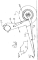
Figure 2 is a schematic cross sectional view along the lines 2-2 ofFigure 1 . -
Figure 3 is a schematic cross sectional view along the lines 3-3 ofFigure 1 . -
Figures 4 ,5 and 6 show a display screen and control input including various screen captures. - In the drawings like characters of reference indicate corresponding parts in the different figures.
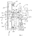
- A combine harvester is shown schematically at 10 and includes ground wheels 11, a
main housing 12 containing the crop processing devices, a cab 13 for the operator and afeeder house 14 for receiving the crop material and feeding it into the housing for processing. The details of combine harvesters are well known to a person skilled in this art so that no detail is necessary for an understanding of this invention. - The
feeder house 14 is mounted on the housing in a manner which allows it to be raised and lowered as indicated at 14A to lift the header carried on the front of the combine. For example the feeder house includescylinders 15 which raise and lower thefront end 16 of the feeder house. - A
header assembly 20 is attached to thefeeder house 14 of thecombine harvester 10 and includes aheader 21 and anadapter 22 which attaches the header to the feeder house. Theadapter 22 is provided to control the feeding of crop by aconveyor 22A into thefeeder house 14 and to provide a lifting force by springs 22B and liftarms 22C of asuspension system 30 to the header to carry it forwardly on the front of the feeder house. - The header is generally of a conventional construction well known to a person skilled in this art and the major components include a
cutter bar 23 for cutting standing crop and a crop transport device defined by a pair ofdrapers collection location 26 at theconveyor 22A for feeding to the combine harvester. - The header includes two ground
engaging gauge wheels adapter 22. The number of wheels can be increased in some cases so that double wheels are used or wheels on an axle but in generally the wheels act so support the header on each side of the support from theadapter 22. - Each
gauge wheel frame 21A (Figure 3 ) of the header from the ground. Theheader frame 21A includes a main transverse beam 21B and a plurality of depending legs 21C which connect to forwardly extending arms 21D carrying theconveyors cutter bar 23. Thus in the example shown thewheel 27 is mounted on a pivot arm 28 pivotally mounted on the header frame at apivot point 21E on the arm 21D so that the arm projects rearwardly from the rear of the frame with thewheel 27 at the rear end so that the wheel is carried on an axle 27B rearwardly of the leg 21C. The arm 28 is attached to the frame by an adjustable link which is typically acylinder 29 operable by a control described hereinafter arranged to be located in the cab 13 of the combine harvester to adjust the position of the gauge wheel relative to the header to a required position so as to adjust the height of cut offrame 21A from the ground. - The
gauge wheels cylinders 29 which are fixed to theframe 21A so that the wheels are mounted on the header such that, when adjusted to the required position, the gauge wheels are fixed relative to the header frame substantially without any suspension floating movement relative thereto. Thus there are preferably no springs or suspension movements allowed and the wheel is rigid to the frame. - The connection between the adapter and the header shown in
Figure 2 includes asuspension system 30 with acenter top link 32 and the twoside suspension arms 22C for carrying the header on the adapter. As is well known, the suspension arrangement allows side to side pivotal movement of the header relative to the adapter as well as vertical floating movement of the header. Thus thesuspension arms 22C are connected to springs 22B which have a spring force which can be adjusted to vary the lifting force applied to the header from the adapter. - Thus the suspension system is adjustable so as to set a required proportion of the weight of the header which is carried on the
feeder house 14 relative to a proportion of the weight of the header which is carried on the gauge wheels 76. - The springs 22B of the suspension system are arranged such that a major part of the weight of the header is carried on the
feeder house 14 and a smaller part is carried on thegauge wheels 27 and typically the proportion of the weight which is carried on the feeder house is of the order of 90%. - The suspension may be arranged such that upward movement of the feeder house acts to increase a lifting force to the header and downward movement of the feeder house acts to decrease the lifting force to the header and/or such that upward movement of the feeder house acts to reduce the separation between the header and the adapter and downward movement of the feeder house acts to increase the separation between the header and the adapter, although these may not occur depending on the mechanical arrangement or may not occur in all parts of the range of movement.
- A
bottom stop 38 is provided which is arranged to limit downward movement of the header relative to theadapter 22 and afloat sensor 39 is provided for sensing a float distance of the header relative to the bottom stop and for generating a signal indicative thereof. - A programmed
control system 40 is provided which includes an automatic headerheight control system 40 arranged to raise and lower thefeeder house 14 in response to the signal from thefloat sensor 39 so as to attempt to maintain the float distance at a required set value. The set value is selected so that the header is free to float between thebottom stop 38 and an upper limit of movement both upwardly and downwardly to an extent to accommodate changes in ground height. Thus the distance of the header from the ground is controlled by the gauge wheels and the weight of the header is primarily carried on the suspension of the feeder house. In the event that the set float distance from thebottom stop 38 decreases because the header has moved downwardly relative to thefeeder house 14, thelift cylinders 15 are operated by thecontrol system 40 using the input from theautomatic height control 39 to lower the feeder house. In the event that the set float distance from the bottom stop increases as detected by thesensor 39 because the header has moved upwardly relative to thefeeder house 14, thelift cylinders 15 are operated by thecontrol 40 to raise the feeder house. - In operation, the header is dropped on the ground until the gauge wheels contact the ground, and causes the header to "float" with respect to the adapter frame. The programmed
control 40 is set so that thecombine feeder house 14 stops lowering when the pre-set amount of header to adapter separation (float) is achieved as detected by thesensor 39. This allows the header to move up and down smoothly to follow the ground contour. To change the cutting height, the cylinders attached to the gauge wheels are operated. The programmedcontrol 40 then causes themain lift cylinders 15 to react so that the pre-set float is maintained. - The
header assembly 20 is thus mounted on thefeeder house 14 of thecombine harvester 12 for movement in a forward working direction D across a field carrying a standing crop to be harvested. - The
header assembly 20 includes theheader 21 with theheader frame 21A carrying thesickle cutter bar 23 across a front of the header frame for cutting standing crop and areel 21R onpivotal support arms 21X for carrying the crop over the cutter bar. Thedrapers collection location 26 for feeding to the combine harvester. - The
adapter 22 forms a mounting arrangement for mounting the header frame on thefeeder house 14 of the combine harvester. The first and second ground engaginggauge wheels header frame 21A at a position spaced rearwardly of thecutter bar 23. - The
cylinders 29 provide first and second adjustable links for adjusting the height of the first andsecond gauge wheels control system 40. - The
cylinder 32 acts in response to an angle input from thecontrol system 40 as an angle adjustment member for tilting theheader frame 21A forwardly and rearwardly about theaxis 22X at the forward end of thesupport arms 22C of thesuspension 22 where theaxis 22X is transverse to the forward working direction D relative to the mounting arrangement. - As shown in
Figure 1 , theheader 21 comprises a three part header with acenter section 211 and twowing sections coupling 214. This arrangement is well known and shown in many patents of the Applicants herein. - The
control system 40 is operable by an operator/driver of the combine through adriver interface 41 in the cab which is arranged for input by the driver of afirst input 45 by acontrol button 45A acting to set a value of a required height of the cutter bar from the ground and asecond input 46 by a control button 46A acting to set a value of required angle of the header relative to the ground. The driver interface is shown in more detail inFigure 4 and includes ascreen 41 which can be a touch screen, and a plurality ofselection buttons 42 and adial 43. - An
icon 44 of thescreen 41 shows to the driver the input parameters above of the required height of the cutter bar from the ground as indicated at 45 and the angle of the header as indicated at 46. The driver can select a value to be inserted at a predetermined time or can insert a series of pre-set values to be selected when required. - It will be appreciated that the height of the cutter bar and the angle of the header are not directly proportional to the adjustment of the
ground wheels cylinders 29 and the adjustment of thecylinder 32. That is the adjustment of thecylinder 32 to adjust the header angle also adjusts the ground height of the cutter bar and also the adjustment of thecylinders 29 to adjust the cutter bar height also changes the header angle. Thus thecontrol system 40 which connects to thedriver interface 41 includes a program responsive to the first andsecond inputs adjustable links 29 and the angle input to theangle adjustment cylinder 32 to automatically obtain theset value 45 of a required height of the cutter bar from the ground and the set avalue 46 of required angle of the header relative to the ground. - This acquisition of the height input and angle input required can be obtained from a look-up table 48 which contains all of the calculated data corresponding to set values of header angles and header height. As an alternative the calculations can carried out in real time with a predetermined algorithm or formula. The look up table 48 provides the required sensor position of the
actuators - The arrangement for controlling the height of the header relative to the combine harvester by adjusting the position of the
feeder house 14 is also arranged so that it automatically retains the required header height using the input signal from thesensor 39 so as to maintain the center part of the header at thefeeder house 14 at the required height to match the height at the gauge wheels. This can be done by providing a direct signal from thesensor 39 to the feeder house control cylinders or by the float height control system described above operated by thecontrol 40. - The combine harvester includes a driver operable control system 401 (
Figure 1 ) and thedriver interface 41 of thecontrol system 40 is a separate control system in the cab but independent of thecontrol system 401 for the combine harvester. - As shown in
Figure 4 , thedriver interface 41 further includes athird input 47 entered using a button 47A acting to set a value of a required speed of the crop transport device ordrapers same interface 41. - Thus in operation the driver selects one of
buttons 45A, 46A and 47A depending on the parameter to be changed and uses the dial or scroll wheel to enter the required value. -
Figure 5 shows a screen of the interface showing feedback sensors on the actuators described above includingactuators float cylinders 22C so that the driver can monitor the actual positions assumed by those components. -
Figure 6 shows a screen of the interface showing three separate presets of the cutting height and header angle as described above.
Claims (15)
- A header assembly (20) for attachment to a feeder house (14) of a combine harvester for movement in a forward working direction across a field carrying a standing crop to be harvested, the header assembly comprising:a header (21) comprising:a header frame (21A);a sickle cutter bar (23) carried across a front of the header frame for cutting standing crop;a reel (21R) for carrying the crop over the cutter bar;a crop transport device (25) for transporting the crop inwardly from ends of the header to a collection location for feeding to the combine harvester;a mounting arrangement (30) for mounting the header frame on the feeder house of the combine harvester;first and second ground engaging gauge wheels (27) on the header frame one on each side of the feeder house;the ground engaging gauge wheels (27) being mounted on the header frame at a position spaced rearwardly of the cutter bar;first and second adjustable links (29) for adjusting the height of the first and second gauge wheels respectively relative to the header frame in response to a height input;an angle adjustment member (32) for tilting the header frame forwardly and rearwardly about an axis transverse to the forward working direction relative to said mounting arrangement in response to an angle input;a control system (40) operable by a driver the header (20) being characterised in that the control system (40) includes a driver interface (41) arranged for input by the driver of:a first input (45) acting to set a value of a required height of the cutter bar from the ground;and a second input (46) acting to set a value of required angle of the header relative to the ground;the control system including a program responsive to the first and second inputs (45, 46) for generating said height input to said first and second adjustable links (29) and said angle input to said angle adjustment member (32) to automatically obtain said set a value of a required height of the cutter bar from the ground and said set a value of required angle of the header relative to the ground.
- The header assembly according to Claim 1 wherein there is provided a height adjustment arrangement for adjusting the height of header (21) relative to the combine harvester and wherein the height of the header (21) relative to the combine harvester is adjusted in association with the height of the first and second wheels (27).
- The header assembly according to Claim 1 or 2 wherein the arrangement for controlling the height of the header relative to the combine harvester automatically retains the header height so as to maintain part of the header at the feeder house at a required height to match the height at the gauge wheels.
- The header assembly according to Claim 3 wherein the header comprises a three part header with a center section (211) and two wing sections (212, 213) where each of the wing sections is each flexibly coupled to the center section.
- The header assembly according to Claim 3 or 4 wherein the height of the header (21) relative to the combine harvester is controlled by raising and lowering the feeder house (14).
- The header assembly according to any one of Claims 1 to 5 wherein there is provided an adapter (22) arranged to be mounted on the feeder house (14) which supports the header on the feeder house including a crop transfer arrangement for carrying the crop material through the adapter to the feeder house (14).
- The header assembly according to any one of Claims 1 to 6 wherein there is provided a floating suspension system (30) for carrying the header on the feeder house (14).
- The header assembly according to Claim 7 wherein the floating suspension system is arranged such that a major part of the weight of the header is carried on the feeder house (14) and a smaller part is carried on the gauge wheels (27).
- The header assembly according to Claim 7 or 8 wherein the floating suspension system (30) is adjustable so as to set a required proportion of the weight of the header which is carried on the feeder house (14) relative to a proportion of the weight of the header which is carried on the gauge wheels (27).
- The header assembly according to any one of Claims 1 to 9 wherein there is provided a float sensor (39) for sensing a float distance of the header relative to a point fixed relative to the feeder house and for generating a signal indicative thereof and an automatic header height control system arranged to raise and lower the feeder house (14) in response to the signal from the float sensor so as to attempt to maintain the float distance at a required set value.
- The header assembly according to any one of Claims 1 to 10 wherein the gauge wheels (27) are mounted on the header frame (21A) such that, when adjusted to the required position, the gauge wheels are fixed relative to the header frame substantially without any suspension floating movement relative thereto.
- The header assembly according to any one of Claims 1 to 11 wherein the driver interface comprises a touch screen (41) mounted in a cab of the combine harvester.
- The header assembly according to any one of Claims 1 to 12 wherein the driver interface (41) is a separate control system independent of a control system for the combine harvester.
- The header assembly according to any one of Claims 1 to 13 wherein the driver interface (41) is integrated with a control system for the combine harvester.
- The header assembly according to any one of Claims 1 to 14 wherein the driver interface (41) includes a third input (47) acting to set a value of a required speed of the crop transport device.
Applications Claiming Priority (2)
| Application Number | Priority Date | Filing Date | Title |
|---|---|---|---|
| US201461969938P | 2014-03-25 | 2014-03-25 | |
| PCT/CA2015/050187 WO2015143550A1 (en) | 2014-03-25 | 2015-03-12 | Controlling cutting height and angle of a combine header |
Publications (3)
| Publication Number | Publication Date |
|---|---|
| EP3122169A1 EP3122169A1 (en) | 2017-02-01 |
| EP3122169A4 EP3122169A4 (en) | 2018-01-03 |
| EP3122169B1 true EP3122169B1 (en) | 2021-09-22 |
Family
ID=54188440
Family Applications (1)
| Application Number | Title | Priority Date | Filing Date |
|---|---|---|---|
| EP15768046.3A Active EP3122169B1 (en) | 2014-03-25 | 2015-03-12 | Controlling cutting height and angle of a combine header |
Country Status (9)
| Country | Link |
|---|---|
| US (1) | US10216156B2 (en) |
| EP (1) | EP3122169B1 (en) |
| AR (1) | AR099796A1 (en) |
| AU (1) | AU2015234578B2 (en) |
| BR (1) | BR112016021970B1 (en) |
| CA (1) | CA2900067C (en) |
| EA (1) | EA032172B1 (en) |
| HU (1) | HUE057434T2 (en) |
| WO (1) | WO2015143550A1 (en) |
Families Citing this family (40)
| Publication number | Priority date | Publication date | Assignee | Title |
|---|---|---|---|---|
| US9775291B2 (en) * | 2014-12-29 | 2017-10-03 | Macdon Industries Ltd. | Gauge wheels for a multi-section agricultural header |
| US9844184B2 (en) * | 2015-03-17 | 2017-12-19 | Agco Corporation | Header position sensing system for an agricultural harvester |
| GB201607568D0 (en) * | 2016-04-29 | 2016-06-15 | Agco Do Brazil Com E Ind Ltda | Harvester header pitch adjustment apparatus |
| CN107371619A (en) * | 2016-05-14 | 2017-11-24 | 勇猛机械股份有限公司 | A kind of harvester cutting bench |
| US10617059B2 (en) * | 2016-06-21 | 2020-04-14 | Macdon Industries Ltd. | Crop machine with an electronically controlled hydraulic cylinder flotation system |
| BE1024333B1 (en) * | 2016-06-23 | 2018-02-01 | Cnh Industrial Belgium Nv | Cutting bar support for a harvesting machine |
| EP3515174B1 (en) | 2016-09-26 | 2020-09-30 | AGCO Corporation | Agricultural harvester with supplemental ground support for transport |
| US10278330B2 (en) * | 2016-10-11 | 2019-05-07 | Deere & Company | Combine feeder house gauge wheels |
| EP3582604B1 (en) * | 2017-02-14 | 2023-10-18 | Precision Planting LLC | Header height control system accounting for change in header pitch |
| US10405474B2 (en) * | 2017-04-30 | 2019-09-10 | Deere & Company | Multilink connection between harvesting head adapter frame and mainframe |
| US10182525B2 (en) | 2017-05-17 | 2019-01-22 | Cnh Industrial America Llc | Feeder and header positioning method |
| BR102017010857A2 (en) * | 2017-05-24 | 2018-12-18 | CNH Industrial Brasil Ltda. | structural assembly for mounting a platform and harvester |
| BR102017010859B1 (en) * | 2017-05-24 | 2022-12-13 | Cnh Industrial Brasil Ltda | STRUCTURAL SET FOR ASSEMBLY OF A PLATFORM |
| CA2974621C (en) * | 2017-07-27 | 2019-11-05 | Macdon Industries Ltd. | Agricultural header with ground engaging gauge member for above ground cutting |
| US10321629B2 (en) * | 2017-07-27 | 2019-06-18 | Macdon Industries Ltd. | Agricultural header with ground engaging gauge member for above ground cutting |
| US10321630B2 (en) * | 2017-07-27 | 2019-06-18 | Macdon Industries Ltd. | Agricultural header with ground engaging gauge members for above ground cutting |
| US10568264B2 (en) * | 2017-12-20 | 2020-02-25 | Cnh Industrial America Llc | Harvester with header lift assembly |
| US10827677B2 (en) * | 2018-01-04 | 2020-11-10 | CNH Industrial America, LLC | Draper header for harvester providing floatation to gauge wheels |
| US10701862B2 (en) * | 2018-02-01 | 2020-07-07 | Macdon Industries Ltd. | Agricultural header with float control |
| US11032970B2 (en) * | 2018-10-30 | 2021-06-15 | Deere & Company | Varying a hydraulic cylinder mechanical advantage to obtain smoother float pressure |
| WO2020101992A1 (en) * | 2018-11-16 | 2020-05-22 | Cnh Industrial America Llc | Self-supporting harvester header system |
| BR112021009507A2 (en) * | 2018-11-16 | 2021-08-17 | Cnh Industrial America Llc | harvester platform having a segment control system |
| US11483970B2 (en) | 2018-11-28 | 2022-11-01 | Cnh Industrial America Llc | System and method for adjusting the orientation of an agricultural harvesting implement based on implement height |
| GB2580976A (en) * | 2019-02-04 | 2020-08-05 | Kverneland Group Kerteminde As | A mower for an agricultural machine |
| US11246259B2 (en) * | 2019-04-26 | 2022-02-15 | Deere & Company | Locking assembly for agricultural combine harvesting head |
| US11516964B2 (en) * | 2019-04-30 | 2022-12-06 | Deere & Company | Position controlled gauge wheels on a harvesting machine header that move with a feeder house move command |
| US11058056B2 (en) | 2019-05-06 | 2021-07-13 | Deere & Company | Gang arm gauge wheel height control for crop harvesting device |
| US11382268B2 (en) | 2019-06-12 | 2022-07-12 | Cnh Industrial America Llc | Header height control for a harvesting head |
| CN110574544A (en) * | 2019-10-16 | 2019-12-17 | 新疆农业大学 | Sunflower harvesting header |
| US11497164B2 (en) | 2019-10-22 | 2022-11-15 | Cnh Industrial America Llc | Header suspension for pivoting header of combine harvester |
| US11412658B2 (en) * | 2019-10-31 | 2022-08-16 | Cnh Industrial America Llc | Torsion balanced harvester head |
| US11464167B2 (en) * | 2019-11-05 | 2022-10-11 | Cnh Industrial America Llc | Road travel system for an agricultural vehicle |
| US11375664B2 (en) * | 2019-11-16 | 2022-07-05 | Cnh Industrial America Llc | Agricultural header with linearly displaceable flex arms |
| US11744178B2 (en) | 2019-11-26 | 2023-09-05 | Cnh Industrial America Llc | Header float system for use with an agricultural windrower or combine |
| US11452259B2 (en) * | 2020-03-17 | 2022-09-27 | Cnh Industrial America Llc | System and method for controlling harvester implement position of an agricultural harvester |
| CN112000022B (en) * | 2020-08-25 | 2023-12-19 | 湖南方彦半导体有限公司 | Intelligent home control system |
| AR125724A1 (en) * | 2021-04-28 | 2023-08-09 | Cnh Ind America Llc | SYSTEMS AND METHODS TO CONTROL THE SPEED AND DIRECTION OF A SIDE CONVEYOR OF AN AGRICULTURAL HEAD |
| AR126249A1 (en) * | 2021-06-30 | 2023-10-04 | Cnh Ind America Llc | SYSTEMS AND METHODS FOR CONTROLLING THE HEIGHT OF A HARVESTING IMPLEMENT IN RELATION TO THE GROUND |
| CA3225940A1 (en) * | 2021-09-10 | 2023-03-16 | Macdon Industries Ltd. | Systems and methods for setting header cut height |
| CN113966667B (en) * | 2021-12-24 | 2022-03-15 | 潍柴雷沃重工股份有限公司 | Harvester header self-adaptive control system based on ground profiling and harvester |
Family Cites Families (11)
| Publication number | Priority date | Publication date | Assignee | Title |
|---|---|---|---|---|
| US3597907A (en) | 1965-02-15 | 1971-08-10 | Love Co J E | Header elevational control system for crop-harvesting machine |
| US6615570B2 (en) | 2001-06-28 | 2003-09-09 | Deere & Company | Header position control with forward contour prediction |
| US6984171B2 (en) * | 2002-07-19 | 2006-01-10 | Cnh America Llc | Hydro-mechanical threshing rotor control system for an agricultural combine |
| CA2505431C (en) * | 2005-03-22 | 2011-10-11 | Macdon Industries Ltd. | Swather with automatic reel control |
| US20090277145A1 (en) | 2008-05-09 | 2009-11-12 | Agco Corporation | Header height control system with multiple potentiometer input |
| US7661251B1 (en) | 2008-08-22 | 2010-02-16 | Deere & Company | Header float system for use with an agricultural windrower or combine |
| CA2665589C (en) * | 2009-05-08 | 2011-05-10 | Macdon Industries Ltd. | Combine header with gauge wheels to control cut height |
| US8245489B2 (en) * | 2009-05-08 | 2012-08-21 | Macdon Industries Ltd | Combine header with gauge wheels to control cut height |
| US7992369B2 (en) | 2009-10-29 | 2011-08-09 | Deere & Company | Agricultural harvester and header height control system |
| US9148998B2 (en) | 2012-08-11 | 2015-10-06 | Deere & Company | Header height control system |
| US10531607B2 (en) * | 2013-07-31 | 2020-01-14 | Cnh Industrial America Llc | Header lateral tilt control with automatic operation in free float and controlled tilt modes |
-
2015
- 2015-03-11 US US14/645,000 patent/US10216156B2/en active Active
- 2015-03-12 EP EP15768046.3A patent/EP3122169B1/en active Active
- 2015-03-12 AU AU2015234578A patent/AU2015234578B2/en active Active
- 2015-03-12 CA CA2900067A patent/CA2900067C/en active Active
- 2015-03-12 HU HUE15768046A patent/HUE057434T2/en unknown
- 2015-03-12 WO PCT/CA2015/050187 patent/WO2015143550A1/en active Application Filing
- 2015-03-12 BR BR112016021970-8A patent/BR112016021970B1/en active IP Right Grant
- 2015-03-12 EA EA201691919A patent/EA032172B1/en not_active IP Right Cessation
- 2015-03-19 AR ARP150100830A patent/AR099796A1/en active IP Right Grant
Also Published As
| Publication number | Publication date |
|---|---|
| CA2900067C (en) | 2016-06-21 |
| CA2900067A1 (en) | 2016-02-03 |
| US20150271999A1 (en) | 2015-10-01 |
| AU2015234578B2 (en) | 2017-02-16 |
| BR112016021970B1 (en) | 2020-11-10 |
| EA032172B1 (en) | 2019-04-30 |
| EP3122169A1 (en) | 2017-02-01 |
| EP3122169A4 (en) | 2018-01-03 |
| HUE057434T2 (en) | 2022-05-28 |
| AU2015234578A1 (en) | 2016-10-06 |
| US10216156B2 (en) | 2019-02-26 |
| WO2015143550A1 (en) | 2015-10-01 |
| EA201691919A1 (en) | 2017-01-30 |
| AR099796A1 (en) | 2016-08-17 |
Similar Documents
| Publication | Publication Date | Title |
|---|---|---|
| EP3122169B1 (en) | Controlling cutting height and angle of a combine header | |
| US8245489B2 (en) | Combine header with gauge wheels to control cut height | |
| US8560182B2 (en) | Implement height control adjustment on agricultural vehicles | |
| CA2665589C (en) | Combine header with gauge wheels to control cut height | |
| EP2779817B1 (en) | Crop harvesting machine with calibration of the header float springs | |
| US9351443B2 (en) | Harvester with automatic depth and level control | |
| EP3363276A1 (en) | Combination flex and rigid header height control in a harvester | |
| EP2420126B1 (en) | Combine header with gauge wheels to control cut height | |
| US20200296892A1 (en) | Forward-looking perception interface and control | |
| AU2010212410B2 (en) | Combine header with gauge wheels to control cut height | |
| JP3434341B2 (en) | Elevation control device of pre-cutting device in combine harvester |
Legal Events
| Date | Code | Title | Description |
|---|---|---|---|
| STAA | Information on the status of an ep patent application or granted ep patent |
Free format text: STATUS: THE INTERNATIONAL PUBLICATION HAS BEEN MADE |
|
| PUAI | Public reference made under article 153(3) epc to a published international application that has entered the european phase |
Free format text: ORIGINAL CODE: 0009012 |
|
| STAA | Information on the status of an ep patent application or granted ep patent |
Free format text: STATUS: REQUEST FOR EXAMINATION WAS MADE |
|
| 17P | Request for examination filed |
Effective date: 20161025 |
|
| AK | Designated contracting states |
Kind code of ref document: A1 Designated state(s): AL AT BE BG CH CY CZ DE DK EE ES FI FR GB GR HR HU IE IS IT LI LT LU LV MC MK MT NL NO PL PT RO RS SE SI SK SM TR |
|
| AX | Request for extension of the european patent |
Extension state: BA ME |
|
| DAV | Request for validation of the european patent (deleted) | ||
| DAX | Request for extension of the european patent (deleted) | ||
| A4 | Supplementary search report drawn up and despatched |
Effective date: 20171201 |
|
| RIC1 | Information provided on ipc code assigned before grant |
Ipc: A01D 41/06 20060101AFI20171127BHEP Ipc: A01D 47/00 20060101ALI20171127BHEP |
|
| GRAP | Despatch of communication of intention to grant a patent |
Free format text: ORIGINAL CODE: EPIDOSNIGR1 |
|
| STAA | Information on the status of an ep patent application or granted ep patent |
Free format text: STATUS: GRANT OF PATENT IS INTENDED |
|
| INTG | Intention to grant announced |
Effective date: 20210507 |
|
| GRAS | Grant fee paid |
Free format text: ORIGINAL CODE: EPIDOSNIGR3 |
|
| GRAA | (expected) grant |
Free format text: ORIGINAL CODE: 0009210 |
|
| STAA | Information on the status of an ep patent application or granted ep patent |
Free format text: STATUS: THE PATENT HAS BEEN GRANTED |
|
| AK | Designated contracting states |
Kind code of ref document: B1 Designated state(s): AL AT BE BG CH CY CZ DE DK EE ES FI FR GB GR HR HU IE IS IT LI LT LU LV MC MK MT NL NO PL PT RO RS SE SI SK SM TR |
|
| REG | Reference to a national code |
Ref country code: GB Ref legal event code: FG4D |
|
| REG | Reference to a national code |
Ref country code: IE Ref legal event code: FG4D |
|
| REG | Reference to a national code |
Ref country code: DE Ref legal event code: R096 Ref document number: 602015073529 Country of ref document: DE |
|
| REG | Reference to a national code |
Ref country code: CH Ref legal event code: EP Ref country code: AT Ref legal event code: REF Ref document number: 1431584 Country of ref document: AT Kind code of ref document: T Effective date: 20211015 |
|
| REG | Reference to a national code |
Ref country code: LT Ref legal event code: MG9D |
|
| REG | Reference to a national code |
Ref country code: NL Ref legal event code: MP Effective date: 20210922 |
|
| PG25 | Lapsed in a contracting state [announced via postgrant information from national office to epo] |
Ref country code: LT Free format text: LAPSE BECAUSE OF FAILURE TO SUBMIT A TRANSLATION OF THE DESCRIPTION OR TO PAY THE FEE WITHIN THE PRESCRIBED TIME-LIMIT Effective date: 20210922 Ref country code: BG Free format text: LAPSE BECAUSE OF FAILURE TO SUBMIT A TRANSLATION OF THE DESCRIPTION OR TO PAY THE FEE WITHIN THE PRESCRIBED TIME-LIMIT Effective date: 20211222 Ref country code: NO Free format text: LAPSE BECAUSE OF FAILURE TO SUBMIT A TRANSLATION OF THE DESCRIPTION OR TO PAY THE FEE WITHIN THE PRESCRIBED TIME-LIMIT Effective date: 20211222 Ref country code: FI Free format text: LAPSE BECAUSE OF FAILURE TO SUBMIT A TRANSLATION OF THE DESCRIPTION OR TO PAY THE FEE WITHIN THE PRESCRIBED TIME-LIMIT Effective date: 20210922 Ref country code: HR Free format text: LAPSE BECAUSE OF FAILURE TO SUBMIT A TRANSLATION OF THE DESCRIPTION OR TO PAY THE FEE WITHIN THE PRESCRIBED TIME-LIMIT Effective date: 20210922 Ref country code: RS Free format text: LAPSE BECAUSE OF FAILURE TO SUBMIT A TRANSLATION OF THE DESCRIPTION OR TO PAY THE FEE WITHIN THE PRESCRIBED TIME-LIMIT Effective date: 20210922 Ref country code: SE Free format text: LAPSE BECAUSE OF FAILURE TO SUBMIT A TRANSLATION OF THE DESCRIPTION OR TO PAY THE FEE WITHIN THE PRESCRIBED TIME-LIMIT Effective date: 20210922 |
|
| REG | Reference to a national code |
Ref country code: AT Ref legal event code: MK05 Ref document number: 1431584 Country of ref document: AT Kind code of ref document: T Effective date: 20210922 |
|
| PG25 | Lapsed in a contracting state [announced via postgrant information from national office to epo] |
Ref country code: LV Free format text: LAPSE BECAUSE OF FAILURE TO SUBMIT A TRANSLATION OF THE DESCRIPTION OR TO PAY THE FEE WITHIN THE PRESCRIBED TIME-LIMIT Effective date: 20210922 Ref country code: GR Free format text: LAPSE BECAUSE OF FAILURE TO SUBMIT A TRANSLATION OF THE DESCRIPTION OR TO PAY THE FEE WITHIN THE PRESCRIBED TIME-LIMIT Effective date: 20211223 |
|
| PG25 | Lapsed in a contracting state [announced via postgrant information from national office to epo] |
Ref country code: AT Free format text: LAPSE BECAUSE OF FAILURE TO SUBMIT A TRANSLATION OF THE DESCRIPTION OR TO PAY THE FEE WITHIN THE PRESCRIBED TIME-LIMIT Effective date: 20210922 |
|
| REG | Reference to a national code |
Ref country code: HU Ref legal event code: AG4A Ref document number: E057434 Country of ref document: HU |
|
| PG25 | Lapsed in a contracting state [announced via postgrant information from national office to epo] |
Ref country code: IS Free format text: LAPSE BECAUSE OF FAILURE TO SUBMIT A TRANSLATION OF THE DESCRIPTION OR TO PAY THE FEE WITHIN THE PRESCRIBED TIME-LIMIT Effective date: 20220122 Ref country code: SK Free format text: LAPSE BECAUSE OF FAILURE TO SUBMIT A TRANSLATION OF THE DESCRIPTION OR TO PAY THE FEE WITHIN THE PRESCRIBED TIME-LIMIT Effective date: 20210922 Ref country code: RO Free format text: LAPSE BECAUSE OF FAILURE TO SUBMIT A TRANSLATION OF THE DESCRIPTION OR TO PAY THE FEE WITHIN THE PRESCRIBED TIME-LIMIT Effective date: 20210922 Ref country code: PT Free format text: LAPSE BECAUSE OF FAILURE TO SUBMIT A TRANSLATION OF THE DESCRIPTION OR TO PAY THE FEE WITHIN THE PRESCRIBED TIME-LIMIT Effective date: 20220124 Ref country code: PL Free format text: LAPSE BECAUSE OF FAILURE TO SUBMIT A TRANSLATION OF THE DESCRIPTION OR TO PAY THE FEE WITHIN THE PRESCRIBED TIME-LIMIT Effective date: 20210922 Ref country code: NL Free format text: LAPSE BECAUSE OF FAILURE TO SUBMIT A TRANSLATION OF THE DESCRIPTION OR TO PAY THE FEE WITHIN THE PRESCRIBED TIME-LIMIT Effective date: 20210922 Ref country code: ES Free format text: LAPSE BECAUSE OF FAILURE TO SUBMIT A TRANSLATION OF THE DESCRIPTION OR TO PAY THE FEE WITHIN THE PRESCRIBED TIME-LIMIT Effective date: 20210922 Ref country code: EE Free format text: LAPSE BECAUSE OF FAILURE TO SUBMIT A TRANSLATION OF THE DESCRIPTION OR TO PAY THE FEE WITHIN THE PRESCRIBED TIME-LIMIT Effective date: 20210922 Ref country code: CZ Free format text: LAPSE BECAUSE OF FAILURE TO SUBMIT A TRANSLATION OF THE DESCRIPTION OR TO PAY THE FEE WITHIN THE PRESCRIBED TIME-LIMIT Effective date: 20210922 Ref country code: AL Free format text: LAPSE BECAUSE OF FAILURE TO SUBMIT A TRANSLATION OF THE DESCRIPTION OR TO PAY THE FEE WITHIN THE PRESCRIBED TIME-LIMIT Effective date: 20210922 |
|
| REG | Reference to a national code |
Ref country code: DE Ref legal event code: R097 Ref document number: 602015073529 Country of ref document: DE |
|
| PG25 | Lapsed in a contracting state [announced via postgrant information from national office to epo] |
Ref country code: DK Free format text: LAPSE BECAUSE OF FAILURE TO SUBMIT A TRANSLATION OF THE DESCRIPTION OR TO PAY THE FEE WITHIN THE PRESCRIBED TIME-LIMIT Effective date: 20210922 |
|
| PLBE | No opposition filed within time limit |
Free format text: ORIGINAL CODE: 0009261 |
|
| STAA | Information on the status of an ep patent application or granted ep patent |
Free format text: STATUS: NO OPPOSITION FILED WITHIN TIME LIMIT |
|
| 26N | No opposition filed |
Effective date: 20220623 |
|
| PG25 | Lapsed in a contracting state [announced via postgrant information from national office to epo] |
Ref country code: MC Free format text: LAPSE BECAUSE OF FAILURE TO SUBMIT A TRANSLATION OF THE DESCRIPTION OR TO PAY THE FEE WITHIN THE PRESCRIBED TIME-LIMIT Effective date: 20210922 |
|
| REG | Reference to a national code |
Ref country code: CH Ref legal event code: PL |
|
| PG25 | Lapsed in a contracting state [announced via postgrant information from national office to epo] |
Ref country code: SI Free format text: LAPSE BECAUSE OF FAILURE TO SUBMIT A TRANSLATION OF THE DESCRIPTION OR TO PAY THE FEE WITHIN THE PRESCRIBED TIME-LIMIT Effective date: 20210922 |
|
| REG | Reference to a national code |
Ref country code: BE Ref legal event code: MM Effective date: 20220331 |
|
| PG25 | Lapsed in a contracting state [announced via postgrant information from national office to epo] |
Ref country code: LU Free format text: LAPSE BECAUSE OF NON-PAYMENT OF DUE FEES Effective date: 20220312 Ref country code: LI Free format text: LAPSE BECAUSE OF NON-PAYMENT OF DUE FEES Effective date: 20220331 Ref country code: IE Free format text: LAPSE BECAUSE OF NON-PAYMENT OF DUE FEES Effective date: 20220312 Ref country code: CH Free format text: LAPSE BECAUSE OF NON-PAYMENT OF DUE FEES Effective date: 20220331 |
|
| PG25 | Lapsed in a contracting state [announced via postgrant information from national office to epo] |
Ref country code: BE Free format text: LAPSE BECAUSE OF NON-PAYMENT OF DUE FEES Effective date: 20220331 |
|
| PGFP | Annual fee paid to national office [announced via postgrant information from national office to epo] |
Ref country code: FR Payment date: 20230324 Year of fee payment: 9 |
|
| PGFP | Annual fee paid to national office [announced via postgrant information from national office to epo] |
Ref country code: HU Payment date: 20230323 Year of fee payment: 9 Ref country code: GB Payment date: 20230322 Year of fee payment: 9 Ref country code: DE Payment date: 20230331 Year of fee payment: 9 |
|
| PGFP | Annual fee paid to national office [announced via postgrant information from national office to epo] |
Ref country code: IT Payment date: 20230328 Year of fee payment: 9 |