EP3121875A1 - Method for manufacturing a miniaturized electrochemical cell and a miniaturized electrochemical cell - Google Patents
Method for manufacturing a miniaturized electrochemical cell and a miniaturized electrochemical cell Download PDFInfo
- Publication number
- EP3121875A1 EP3121875A1 EP15306180.9A EP15306180A EP3121875A1 EP 3121875 A1 EP3121875 A1 EP 3121875A1 EP 15306180 A EP15306180 A EP 15306180A EP 3121875 A1 EP3121875 A1 EP 3121875A1
- Authority
- EP
- European Patent Office
- Prior art keywords
- layer
- support
- materials
- conducting material
- electrode
- Prior art date
- Legal status (The legal status is an assumption and is not a legal conclusion. Google has not performed a legal analysis and makes no representation as to the accuracy of the status listed.)
- Withdrawn
Links
- 238000000034 method Methods 0.000 title claims abstract description 63
- 238000004519 manufacturing process Methods 0.000 title claims abstract description 26
- 239000000463 material Substances 0.000 claims abstract description 108
- 239000004020 conductor Substances 0.000 claims abstract description 50
- 239000002245 particle Substances 0.000 claims abstract description 24
- 239000004065 semiconductor Substances 0.000 claims abstract description 23
- 238000000151 deposition Methods 0.000 claims abstract description 20
- 239000012777 electrically insulating material Substances 0.000 claims abstract description 20
- 230000000087 stabilizing effect Effects 0.000 claims abstract description 11
- VYPSYNLAJGMNEJ-UHFFFAOYSA-N Silicium dioxide Chemical compound O=[Si]=O VYPSYNLAJGMNEJ-UHFFFAOYSA-N 0.000 claims description 99
- 239000000377 silicon dioxide Substances 0.000 claims description 44
- 238000004070 electrodeposition Methods 0.000 claims description 28
- 229910052737 gold Inorganic materials 0.000 claims description 27
- 239000011521 glass Substances 0.000 claims description 26
- 239000000758 substrate Substances 0.000 claims description 23
- 229910052709 silver Inorganic materials 0.000 claims description 21
- 229910052759 nickel Inorganic materials 0.000 claims description 18
- QAOWNCQODCNURD-UHFFFAOYSA-N Sulfuric acid Chemical compound OS(O)(=O)=O QAOWNCQODCNURD-UHFFFAOYSA-N 0.000 claims description 14
- 229920000767 polyaniline Polymers 0.000 claims description 10
- 229920000128 polypyrrole Polymers 0.000 claims description 10
- 239000002904 solvent Substances 0.000 claims description 10
- GNFTZDOKVXKIBK-UHFFFAOYSA-N 3-(2-methoxyethoxy)benzohydrazide Chemical compound COCCOC1=CC=CC(C(=O)NN)=C1 GNFTZDOKVXKIBK-UHFFFAOYSA-N 0.000 claims description 9
- FGUUSXIOTUKUDN-IBGZPJMESA-N C1(=CC=CC=C1)N1C2=C(NC([C@H](C1)NC=1OC(=NN=1)C1=CC=CC=C1)=O)C=CC=C2 Chemical compound C1(=CC=CC=C1)N1C2=C(NC([C@H](C1)NC=1OC(=NN=1)C1=CC=CC=C1)=O)C=CC=C2 FGUUSXIOTUKUDN-IBGZPJMESA-N 0.000 claims description 9
- 229910052802 copper Inorganic materials 0.000 claims description 9
- KRHYYFGTRYWZRS-UHFFFAOYSA-N Fluorane Chemical compound F KRHYYFGTRYWZRS-UHFFFAOYSA-N 0.000 claims description 8
- 229910052804 chromium Inorganic materials 0.000 claims description 7
- 229910052681 coesite Inorganic materials 0.000 claims description 6
- 229910052906 cristobalite Inorganic materials 0.000 claims description 6
- -1 poly(styrene sulfonate) Polymers 0.000 claims description 6
- 229910052682 stishovite Inorganic materials 0.000 claims description 6
- 229910052905 tridymite Inorganic materials 0.000 claims description 6
- GKWLILHTTGWKLQ-UHFFFAOYSA-N 2,3-dihydrothieno[3,4-b][1,4]dioxine Chemical compound O1CCOC2=CSC=C21 GKWLILHTTGWKLQ-UHFFFAOYSA-N 0.000 claims description 5
- DGAQECJNVWCQMB-PUAWFVPOSA-M Ilexoside XXIX Chemical compound C[C@@H]1CC[C@@]2(CC[C@@]3(C(=CC[C@H]4[C@]3(CC[C@@H]5[C@@]4(CC[C@@H](C5(C)C)OS(=O)(=O)[O-])C)C)[C@@H]2[C@]1(C)O)C)C(=O)O[C@H]6[C@@H]([C@H]([C@@H]([C@H](O6)CO)O)O)O.[Na+] DGAQECJNVWCQMB-PUAWFVPOSA-M 0.000 claims description 5
- 229920000144 PEDOT:PSS Polymers 0.000 claims description 5
- HSFWRNGVRCDJHI-UHFFFAOYSA-N alpha-acetylene Natural products C#C HSFWRNGVRCDJHI-UHFFFAOYSA-N 0.000 claims description 5
- 229910052763 palladium Inorganic materials 0.000 claims description 5
- 229910052697 platinum Inorganic materials 0.000 claims description 5
- 229920001467 poly(styrenesulfonates) Polymers 0.000 claims description 5
- 229920001197 polyacetylene Polymers 0.000 claims description 5
- 239000011734 sodium Substances 0.000 claims description 5
- 229910052708 sodium Inorganic materials 0.000 claims description 5
- 229910052725 zinc Inorganic materials 0.000 claims description 5
- GRYLNZFGIOXLOG-UHFFFAOYSA-N Nitric acid Chemical compound O[N+]([O-])=O GRYLNZFGIOXLOG-UHFFFAOYSA-N 0.000 claims description 4
- 229910017604 nitric acid Inorganic materials 0.000 claims description 4
- 229920003023 plastic Polymers 0.000 claims description 4
- 239000004033 plastic Substances 0.000 claims description 4
- 239000004793 Polystyrene Substances 0.000 claims description 3
- XUIMIQQOPSSXEZ-UHFFFAOYSA-N Silicon Chemical compound [Si] XUIMIQQOPSSXEZ-UHFFFAOYSA-N 0.000 claims description 3
- 239000000853 adhesive Substances 0.000 claims description 3
- 230000001070 adhesive effect Effects 0.000 claims description 3
- 239000003822 epoxy resin Substances 0.000 claims description 3
- 229920000647 polyepoxide Polymers 0.000 claims description 3
- 229920002223 polystyrene Polymers 0.000 claims description 3
- 229910052710 silicon Inorganic materials 0.000 claims description 3
- 239000010703 silicon Substances 0.000 claims description 3
- 230000005518 electrochemistry Effects 0.000 abstract 1
- 239000010410 layer Substances 0.000 description 53
- 239000010931 gold Substances 0.000 description 28
- PXHVJJICTQNCMI-UHFFFAOYSA-N nickel Substances [Ni] PXHVJJICTQNCMI-UHFFFAOYSA-N 0.000 description 28
- 239000000243 solution Substances 0.000 description 27
- 210000004027 cell Anatomy 0.000 description 26
- PCHJSUWPFVWCPO-UHFFFAOYSA-N gold Chemical group [Au] PCHJSUWPFVWCPO-UHFFFAOYSA-N 0.000 description 21
- 239000002105 nanoparticle Substances 0.000 description 19
- 230000015572 biosynthetic process Effects 0.000 description 17
- 238000003786 synthesis reaction Methods 0.000 description 16
- 238000002360 preparation method Methods 0.000 description 15
- WYTZZXDRDKSJID-UHFFFAOYSA-N (3-aminopropyl)triethoxysilane Chemical compound CCO[Si](OCC)(OCC)CCCN WYTZZXDRDKSJID-UHFFFAOYSA-N 0.000 description 13
- BQCADISMDOOEFD-UHFFFAOYSA-N Silver Chemical compound [Ag] BQCADISMDOOEFD-UHFFFAOYSA-N 0.000 description 13
- 239000004332 silver Substances 0.000 description 13
- XLYOFNOQVPJJNP-UHFFFAOYSA-N water Substances O XLYOFNOQVPJJNP-UHFFFAOYSA-N 0.000 description 11
- 239000011324 bead Substances 0.000 description 9
- 239000000203 mixture Substances 0.000 description 9
- QGZKDVFQNNGYKY-UHFFFAOYSA-N Ammonia Chemical compound N QGZKDVFQNNGYKY-UHFFFAOYSA-N 0.000 description 8
- FAPWRFPIFSIZLT-UHFFFAOYSA-M Sodium chloride Chemical compound [Na+].[Cl-] FAPWRFPIFSIZLT-UHFFFAOYSA-M 0.000 description 8
- 238000002484 cyclic voltammetry Methods 0.000 description 8
- BOTDANWDWHJENH-UHFFFAOYSA-N Tetraethyl orthosilicate Chemical compound CCO[Si](OCC)(OCC)OCC BOTDANWDWHJENH-UHFFFAOYSA-N 0.000 description 7
- 239000010949 copper Substances 0.000 description 7
- 238000005530 etching Methods 0.000 description 6
- 230000008569 process Effects 0.000 description 6
- SQGYOTSLMSWVJD-UHFFFAOYSA-N silver(1+) nitrate Chemical compound [Ag+].[O-]N(=O)=O SQGYOTSLMSWVJD-UHFFFAOYSA-N 0.000 description 6
- LFQSCWFLJHTTHZ-UHFFFAOYSA-N Ethanol Chemical compound CCO LFQSCWFLJHTTHZ-UHFFFAOYSA-N 0.000 description 5
- WQZGKKKJIJFFOK-GASJEMHNSA-N Glucose Natural products OC[C@H]1OC(O)[C@H](O)[C@@H](O)[C@@H]1O WQZGKKKJIJFFOK-GASJEMHNSA-N 0.000 description 5
- 229910021607 Silver chloride Inorganic materials 0.000 description 5
- 239000013078 crystal Substances 0.000 description 5
- 230000008021 deposition Effects 0.000 description 5
- 239000008103 glucose Substances 0.000 description 5
- 230000003301 hydrolyzing effect Effects 0.000 description 5
- HKZLPVFGJNLROG-UHFFFAOYSA-M silver monochloride Chemical compound [Cl-].[Ag+] HKZLPVFGJNLROG-UHFFFAOYSA-M 0.000 description 5
- 239000000725 suspension Substances 0.000 description 5
- 239000012031 Tollens' reagent Substances 0.000 description 4
- 229910021529 ammonia Inorganic materials 0.000 description 4
- 125000004122 cyclic group Chemical group 0.000 description 4
- 238000001465 metallisation Methods 0.000 description 4
- 239000001301 oxygen Substances 0.000 description 4
- 229910052760 oxygen Inorganic materials 0.000 description 4
- 238000006722 reduction reaction Methods 0.000 description 4
- 239000000523 sample Substances 0.000 description 4
- 238000004626 scanning electron microscopy Methods 0.000 description 4
- 239000011780 sodium chloride Substances 0.000 description 4
- 241000252506 Characiformes Species 0.000 description 3
- YMWUJEATGCHHMB-UHFFFAOYSA-N Dichloromethane Chemical compound ClCCl YMWUJEATGCHHMB-UHFFFAOYSA-N 0.000 description 3
- HEMHJVSKTPXQMS-UHFFFAOYSA-M Sodium hydroxide Chemical compound [OH-].[Na+] HEMHJVSKTPXQMS-UHFFFAOYSA-M 0.000 description 3
- QVGXLLKOCUKJST-UHFFFAOYSA-N atomic oxygen Chemical compound [O] QVGXLLKOCUKJST-UHFFFAOYSA-N 0.000 description 3
- 238000004140 cleaning Methods 0.000 description 3
- 230000006835 compression Effects 0.000 description 3
- 238000007906 compression Methods 0.000 description 3
- 238000000502 dialysis Methods 0.000 description 3
- 239000003792 electrolyte Substances 0.000 description 3
- 238000009713 electroplating Methods 0.000 description 3
- 238000002474 experimental method Methods 0.000 description 3
- 238000002156 mixing Methods 0.000 description 3
- 229940074355 nitric acid Drugs 0.000 description 3
- 239000003973 paint Substances 0.000 description 3
- 239000011148 porous material Substances 0.000 description 3
- 230000009467 reduction Effects 0.000 description 3
- 229960001516 silver nitrate Drugs 0.000 description 3
- 229910001961 silver nitrate Inorganic materials 0.000 description 3
- 238000004809 thin layer chromatography Methods 0.000 description 3
- 238000005406 washing Methods 0.000 description 3
- 229920001817 Agar Polymers 0.000 description 2
- XKRFYHLGVUSROY-UHFFFAOYSA-N Argon Chemical compound [Ar] XKRFYHLGVUSROY-UHFFFAOYSA-N 0.000 description 2
- HEDRZPFGACZZDS-UHFFFAOYSA-N Chloroform Chemical compound ClC(Cl)Cl HEDRZPFGACZZDS-UHFFFAOYSA-N 0.000 description 2
- RYGMFSIKBFXOCR-UHFFFAOYSA-N Copper Chemical compound [Cu] RYGMFSIKBFXOCR-UHFFFAOYSA-N 0.000 description 2
- MHAJPDPJQMAIIY-UHFFFAOYSA-N Hydrogen peroxide Chemical compound OO MHAJPDPJQMAIIY-UHFFFAOYSA-N 0.000 description 2
- 238000001074 Langmuir--Blodgett assembly Methods 0.000 description 2
- 239000008272 agar Substances 0.000 description 2
- 230000004888 barrier function Effects 0.000 description 2
- 238000004364 calculation method Methods 0.000 description 2
- 239000011248 coating agent Substances 0.000 description 2
- 238000000576 coating method Methods 0.000 description 2
- 150000001875 compounds Chemical class 0.000 description 2
- 229920006335 epoxy glue Polymers 0.000 description 2
- 150000002500 ions Chemical class 0.000 description 2
- 230000004048 modification Effects 0.000 description 2
- 238000012986 modification Methods 0.000 description 2
- 239000010944 silver (metal) Substances 0.000 description 2
- 229910000108 silver(I,III) oxide Inorganic materials 0.000 description 2
- 238000000527 sonication Methods 0.000 description 2
- 239000006228 supernatant Substances 0.000 description 2
- 229910017611 Ag(NH3)2 Inorganic materials 0.000 description 1
- 239000005995 Aluminium silicate Substances 0.000 description 1
- BPQQTUXANYXVAA-UHFFFAOYSA-N Orthosilicate Chemical compound [O-][Si]([O-])([O-])[O-] BPQQTUXANYXVAA-UHFFFAOYSA-N 0.000 description 1
- 229910000831 Steel Inorganic materials 0.000 description 1
- 239000004809 Teflon Substances 0.000 description 1
- 229920006362 Teflon® Polymers 0.000 description 1
- 239000002253 acid Substances 0.000 description 1
- 238000004220 aggregation Methods 0.000 description 1
- 230000002776 aggregation Effects 0.000 description 1
- PZZYQPZGQPZBDN-UHFFFAOYSA-N aluminium silicate Chemical compound O=[Al]O[Si](=O)O[Al]=O PZZYQPZGQPZBDN-UHFFFAOYSA-N 0.000 description 1
- 229910000323 aluminium silicate Inorganic materials 0.000 description 1
- 235000012211 aluminium silicate Nutrition 0.000 description 1
- 239000003945 anionic surfactant Substances 0.000 description 1
- 238000013459 approach Methods 0.000 description 1
- 229910052786 argon Inorganic materials 0.000 description 1
- HXCHRJMJMALFHP-UHFFFAOYSA-N azanium;ethanol;hydroxide Chemical compound N.O.CCO HXCHRJMJMALFHP-UHFFFAOYSA-N 0.000 description 1
- 239000003637 basic solution Substances 0.000 description 1
- 239000002551 biofuel Substances 0.000 description 1
- 238000005119 centrifugation Methods 0.000 description 1
- 238000012512 characterization method Methods 0.000 description 1
- 239000003153 chemical reaction reagent Substances 0.000 description 1
- 239000003638 chemical reducing agent Substances 0.000 description 1
- UXTMROKLAAOEQO-UHFFFAOYSA-N chloroform;ethanol Chemical compound CCO.ClC(Cl)Cl UXTMROKLAAOEQO-UHFFFAOYSA-N 0.000 description 1
- 239000010415 colloidal nanoparticle Substances 0.000 description 1
- 239000002131 composite material Substances 0.000 description 1
- 239000002322 conducting polymer Substances 0.000 description 1
- 229920001940 conductive polymer Polymers 0.000 description 1
- 238000012790 confirmation Methods 0.000 description 1
- 238000011109 contamination Methods 0.000 description 1
- 230000002596 correlated effect Effects 0.000 description 1
- 238000005859 coupling reaction Methods 0.000 description 1
- 230000001186 cumulative effect Effects 0.000 description 1
- 230000001419 dependent effect Effects 0.000 description 1
- 238000007598 dipping method Methods 0.000 description 1
- 239000000428 dust Substances 0.000 description 1
- 238000002848 electrochemical method Methods 0.000 description 1
- 238000003487 electrochemical reaction Methods 0.000 description 1
- 239000008151 electrolyte solution Substances 0.000 description 1
- 229920006332 epoxy adhesive Polymers 0.000 description 1
- 238000001704 evaporation Methods 0.000 description 1
- 210000003722 extracellular fluid Anatomy 0.000 description 1
- 239000000446 fuel Substances 0.000 description 1
- 238000007306 functionalization reaction Methods 0.000 description 1
- 150000002343 gold Chemical class 0.000 description 1
- 230000007062 hydrolysis Effects 0.000 description 1
- 238000006460 hydrolysis reaction Methods 0.000 description 1
- 229920001477 hydrophilic polymer Polymers 0.000 description 1
- 230000010354 integration Effects 0.000 description 1
- 238000011835 investigation Methods 0.000 description 1
- 239000007788 liquid Substances 0.000 description 1
- 238000005259 measurement Methods 0.000 description 1
- 230000007246 mechanism Effects 0.000 description 1
- 239000002102 nanobead Substances 0.000 description 1
- 238000000399 optical microscopy Methods 0.000 description 1
- 230000010355 oscillation Effects 0.000 description 1
- 229920003229 poly(methyl methacrylate) Polymers 0.000 description 1
- 238000006068 polycondensation reaction Methods 0.000 description 1
- 239000004926 polymethyl methacrylate Substances 0.000 description 1
- 238000001556 precipitation Methods 0.000 description 1
- 230000001681 protective effect Effects 0.000 description 1
- 238000000746 purification Methods 0.000 description 1
- 239000010453 quartz Substances 0.000 description 1
- 239000003507 refrigerant Substances 0.000 description 1
- 238000005096 rolling process Methods 0.000 description 1
- 239000002356 single layer Substances 0.000 description 1
- 229940083608 sodium hydroxide Drugs 0.000 description 1
- 235000011121 sodium hydroxide Nutrition 0.000 description 1
- DAJSVUQLFFJUSX-UHFFFAOYSA-M sodium;dodecane-1-sulfonate Chemical compound [Na+].CCCCCCCCCCCCS([O-])(=O)=O DAJSVUQLFFJUSX-UHFFFAOYSA-M 0.000 description 1
- HUAUNKAZQWMVFY-UHFFFAOYSA-M sodium;oxocalcium;hydroxide Chemical compound [OH-].[Na+].[Ca]=O HUAUNKAZQWMVFY-UHFFFAOYSA-M 0.000 description 1
- 239000007787 solid Substances 0.000 description 1
- 239000012798 spherical particle Substances 0.000 description 1
- 239000010959 steel Substances 0.000 description 1
- 238000003756 stirring Methods 0.000 description 1
- 238000007920 subcutaneous administration Methods 0.000 description 1
- 239000001117 sulphuric acid Substances 0.000 description 1
- 235000011149 sulphuric acid Nutrition 0.000 description 1
- 239000003115 supporting electrolyte Substances 0.000 description 1
- 231100000331 toxic Toxicity 0.000 description 1
- 230000002588 toxic effect Effects 0.000 description 1
- 238000011282 treatment Methods 0.000 description 1
Images


Classifications
-
- H—ELECTRICITY
- H01—ELECTRIC ELEMENTS
- H01M—PROCESSES OR MEANS, e.g. BATTERIES, FOR THE DIRECT CONVERSION OF CHEMICAL ENERGY INTO ELECTRICAL ENERGY
- H01M4/00—Electrodes
- H01M4/02—Electrodes composed of, or comprising, active material
- H01M4/04—Processes of manufacture in general
- H01M4/0402—Methods of deposition of the material
-
- C—CHEMISTRY; METALLURGY
- C25—ELECTROLYTIC OR ELECTROPHORETIC PROCESSES; APPARATUS THEREFOR
- C25D—PROCESSES FOR THE ELECTROLYTIC OR ELECTROPHORETIC PRODUCTION OF COATINGS; ELECTROFORMING; APPARATUS THEREFOR
- C25D1/00—Electroforming
- C25D1/006—Nanostructures, e.g. using aluminium anodic oxidation templates [AAO]
-
- C—CHEMISTRY; METALLURGY
- C25—ELECTROLYTIC OR ELECTROPHORETIC PROCESSES; APPARATUS THEREFOR
- C25D—PROCESSES FOR THE ELECTROLYTIC OR ELECTROPHORETIC PRODUCTION OF COATINGS; ELECTROFORMING; APPARATUS THEREFOR
- C25D1/00—Electroforming
- C25D1/02—Tubes; Rings; Hollow bodies
-
- C—CHEMISTRY; METALLURGY
- C25—ELECTROLYTIC OR ELECTROPHORETIC PROCESSES; APPARATUS THEREFOR
- C25D—PROCESSES FOR THE ELECTROLYTIC OR ELECTROPHORETIC PRODUCTION OF COATINGS; ELECTROFORMING; APPARATUS THEREFOR
- C25D1/00—Electroforming
- C25D1/08—Perforated or foraminous objects, e.g. sieves
-
- C—CHEMISTRY; METALLURGY
- C25—ELECTROLYTIC OR ELECTROPHORETIC PROCESSES; APPARATUS THEREFOR
- C25D—PROCESSES FOR THE ELECTROLYTIC OR ELECTROPHORETIC PRODUCTION OF COATINGS; ELECTROFORMING; APPARATUS THEREFOR
- C25D3/00—Electroplating: Baths therefor
- C25D3/02—Electroplating: Baths therefor from solutions
- C25D3/12—Electroplating: Baths therefor from solutions of nickel or cobalt
-
- C—CHEMISTRY; METALLURGY
- C25—ELECTROLYTIC OR ELECTROPHORETIC PROCESSES; APPARATUS THEREFOR
- C25D—PROCESSES FOR THE ELECTROLYTIC OR ELECTROPHORETIC PRODUCTION OF COATINGS; ELECTROFORMING; APPARATUS THEREFOR
- C25D3/00—Electroplating: Baths therefor
- C25D3/02—Electroplating: Baths therefor from solutions
- C25D3/46—Electroplating: Baths therefor from solutions of silver
-
- C—CHEMISTRY; METALLURGY
- C25—ELECTROLYTIC OR ELECTROPHORETIC PROCESSES; APPARATUS THEREFOR
- C25D—PROCESSES FOR THE ELECTROLYTIC OR ELECTROPHORETIC PRODUCTION OF COATINGS; ELECTROFORMING; APPARATUS THEREFOR
- C25D3/00—Electroplating: Baths therefor
- C25D3/02—Electroplating: Baths therefor from solutions
- C25D3/48—Electroplating: Baths therefor from solutions of gold
-
- C—CHEMISTRY; METALLURGY
- C25—ELECTROLYTIC OR ELECTROPHORETIC PROCESSES; APPARATUS THEREFOR
- C25D—PROCESSES FOR THE ELECTROLYTIC OR ELECTROPHORETIC PRODUCTION OF COATINGS; ELECTROFORMING; APPARATUS THEREFOR
- C25D5/00—Electroplating characterised by the process; Pretreatment or after-treatment of workpieces
- C25D5/10—Electroplating with more than one layer of the same or of different metals
- C25D5/12—Electroplating with more than one layer of the same or of different metals at least one layer being of nickel or chromium
-
- C—CHEMISTRY; METALLURGY
- C25—ELECTROLYTIC OR ELECTROPHORETIC PROCESSES; APPARATUS THEREFOR
- C25D—PROCESSES FOR THE ELECTROLYTIC OR ELECTROPHORETIC PRODUCTION OF COATINGS; ELECTROFORMING; APPARATUS THEREFOR
- C25D5/00—Electroplating characterised by the process; Pretreatment or after-treatment of workpieces
- C25D5/60—Electroplating characterised by the structure or texture of the layers
- C25D5/605—Surface topography of the layers, e.g. rough, dendritic or nodular layers
- C25D5/611—Smooth layers
-
- C—CHEMISTRY; METALLURGY
- C25—ELECTROLYTIC OR ELECTROPHORETIC PROCESSES; APPARATUS THEREFOR
- C25D—PROCESSES FOR THE ELECTROLYTIC OR ELECTROPHORETIC PRODUCTION OF COATINGS; ELECTROFORMING; APPARATUS THEREFOR
- C25D5/00—Electroplating characterised by the process; Pretreatment or after-treatment of workpieces
- C25D5/60—Electroplating characterised by the structure or texture of the layers
- C25D5/623—Porosity of the layers
-
- C—CHEMISTRY; METALLURGY
- C25—ELECTROLYTIC OR ELECTROPHORETIC PROCESSES; APPARATUS THEREFOR
- C25D—PROCESSES FOR THE ELECTROLYTIC OR ELECTROPHORETIC PRODUCTION OF COATINGS; ELECTROFORMING; APPARATUS THEREFOR
- C25D7/00—Electroplating characterised by the article coated
- C25D7/06—Wires; Strips; Foils
- C25D7/0607—Wires
-
- H—ELECTRICITY
- H01—ELECTRIC ELEMENTS
- H01M—PROCESSES OR MEANS, e.g. BATTERIES, FOR THE DIRECT CONVERSION OF CHEMICAL ENERGY INTO ELECTRICAL ENERGY
- H01M10/00—Secondary cells; Manufacture thereof
- H01M10/04—Construction or manufacture in general
- H01M10/0436—Small-sized flat cells or batteries for portable equipment
-
- H—ELECTRICITY
- H01—ELECTRIC ELEMENTS
- H01M—PROCESSES OR MEANS, e.g. BATTERIES, FOR THE DIRECT CONVERSION OF CHEMICAL ENERGY INTO ELECTRICAL ENERGY
- H01M10/00—Secondary cells; Manufacture thereof
- H01M10/36—Accumulators not provided for in groups H01M10/05-H01M10/34
- H01M10/38—Construction or manufacture
-
- H—ELECTRICITY
- H01—ELECTRIC ELEMENTS
- H01M—PROCESSES OR MEANS, e.g. BATTERIES, FOR THE DIRECT CONVERSION OF CHEMICAL ENERGY INTO ELECTRICAL ENERGY
- H01M4/00—Electrodes
- H01M4/02—Electrodes composed of, or comprising, active material
- H01M4/04—Processes of manufacture in general
- H01M4/0438—Processes of manufacture in general by electrochemical processing
- H01M4/045—Electrochemical coating; Electrochemical impregnation
- H01M4/0452—Electrochemical coating; Electrochemical impregnation from solutions
-
- H—ELECTRICITY
- H01—ELECTRIC ELEMENTS
- H01M—PROCESSES OR MEANS, e.g. BATTERIES, FOR THE DIRECT CONVERSION OF CHEMICAL ENERGY INTO ELECTRICAL ENERGY
- H01M4/00—Electrodes
- H01M4/02—Electrodes composed of, or comprising, active material
- H01M4/06—Electrodes for primary cells
- H01M4/08—Processes of manufacture
- H01M4/12—Processes of manufacture of consumable metal or alloy electrodes
-
- H—ELECTRICITY
- H01—ELECTRIC ELEMENTS
- H01M—PROCESSES OR MEANS, e.g. BATTERIES, FOR THE DIRECT CONVERSION OF CHEMICAL ENERGY INTO ELECTRICAL ENERGY
- H01M4/00—Electrodes
- H01M4/02—Electrodes composed of, or comprising, active material
- H01M4/13—Electrodes for accumulators with non-aqueous electrolyte, e.g. for lithium-accumulators; Processes of manufacture thereof
- H01M4/139—Processes of manufacture
- H01M4/1395—Processes of manufacture of electrodes based on metals, Si or alloys
-
- H—ELECTRICITY
- H01—ELECTRIC ELEMENTS
- H01M—PROCESSES OR MEANS, e.g. BATTERIES, FOR THE DIRECT CONVERSION OF CHEMICAL ENERGY INTO ELECTRICAL ENERGY
- H01M4/00—Electrodes
- H01M4/02—Electrodes composed of, or comprising, active material
- H01M4/36—Selection of substances as active materials, active masses, active liquids
- H01M4/38—Selection of substances as active materials, active masses, active liquids of elements or alloys
-
- H—ELECTRICITY
- H01—ELECTRIC ELEMENTS
- H01M—PROCESSES OR MEANS, e.g. BATTERIES, FOR THE DIRECT CONVERSION OF CHEMICAL ENERGY INTO ELECTRICAL ENERGY
- H01M4/00—Electrodes
- H01M4/02—Electrodes composed of, or comprising, active material
- H01M4/64—Carriers or collectors
- H01M4/66—Selection of materials
- H01M4/661—Metal or alloys, e.g. alloy coatings
-
- H—ELECTRICITY
- H01—ELECTRIC ELEMENTS
- H01M—PROCESSES OR MEANS, e.g. BATTERIES, FOR THE DIRECT CONVERSION OF CHEMICAL ENERGY INTO ELECTRICAL ENERGY
- H01M4/00—Electrodes
- H01M4/02—Electrodes composed of, or comprising, active material
- H01M4/64—Carriers or collectors
- H01M4/70—Carriers or collectors characterised by shape or form
- H01M4/76—Containers for holding the active material, e.g. tubes, capsules
- H01M4/765—Tubular type or pencil type electrodes; tubular or multitubular sheaths or covers of insulating material for said tubular-type electrodes
-
- H—ELECTRICITY
- H01—ELECTRIC ELEMENTS
- H01M—PROCESSES OR MEANS, e.g. BATTERIES, FOR THE DIRECT CONVERSION OF CHEMICAL ENERGY INTO ELECTRICAL ENERGY
- H01M4/00—Electrodes
- H01M4/86—Inert electrodes with catalytic activity, e.g. for fuel cells
- H01M4/8605—Porous electrodes
- H01M4/8626—Porous electrodes characterised by the form
-
- H—ELECTRICITY
- H01—ELECTRIC ELEMENTS
- H01M—PROCESSES OR MEANS, e.g. BATTERIES, FOR THE DIRECT CONVERSION OF CHEMICAL ENERGY INTO ELECTRICAL ENERGY
- H01M4/00—Electrodes
- H01M4/86—Inert electrodes with catalytic activity, e.g. for fuel cells
- H01M4/88—Processes of manufacture
- H01M4/8825—Methods for deposition of the catalytic active composition
- H01M4/8853—Electrodeposition
-
- H—ELECTRICITY
- H01—ELECTRIC ELEMENTS
- H01M—PROCESSES OR MEANS, e.g. BATTERIES, FOR THE DIRECT CONVERSION OF CHEMICAL ENERGY INTO ELECTRICAL ENERGY
- H01M4/00—Electrodes
- H01M4/86—Inert electrodes with catalytic activity, e.g. for fuel cells
- H01M4/90—Selection of catalytic material
- H01M4/9041—Metals or alloys
-
- H—ELECTRICITY
- H01—ELECTRIC ELEMENTS
- H01M—PROCESSES OR MEANS, e.g. BATTERIES, FOR THE DIRECT CONVERSION OF CHEMICAL ENERGY INTO ELECTRICAL ENERGY
- H01M6/00—Primary cells; Manufacture thereof
- H01M6/02—Details
-
- H—ELECTRICITY
- H01—ELECTRIC ELEMENTS
- H01M—PROCESSES OR MEANS, e.g. BATTERIES, FOR THE DIRECT CONVERSION OF CHEMICAL ENERGY INTO ELECTRICAL ENERGY
- H01M8/00—Fuel cells; Manufacture thereof
- H01M8/16—Biochemical fuel cells, i.e. cells in which microorganisms function as catalysts
-
- A—HUMAN NECESSITIES
- A61—MEDICAL OR VETERINARY SCIENCE; HYGIENE
- A61B—DIAGNOSIS; SURGERY; IDENTIFICATION
- A61B2560/00—Constructional details of operational features of apparatus; Accessories for medical measuring apparatus
- A61B2560/02—Operational features
- A61B2560/0204—Operational features of power management
- A61B2560/0214—Operational features of power management of power generation or supply
-
- A—HUMAN NECESSITIES
- A61—MEDICAL OR VETERINARY SCIENCE; HYGIENE
- A61B—DIAGNOSIS; SURGERY; IDENTIFICATION
- A61B5/00—Measuring for diagnostic purposes; Identification of persons
- A61B5/68—Arrangements of detecting, measuring or recording means, e.g. sensors, in relation to patient
- A61B5/6846—Arrangements of detecting, measuring or recording means, e.g. sensors, in relation to patient specially adapted to be brought in contact with an internal body part, i.e. invasive
- A61B5/6847—Arrangements of detecting, measuring or recording means, e.g. sensors, in relation to patient specially adapted to be brought in contact with an internal body part, i.e. invasive mounted on an invasive device
- A61B5/686—Permanently implanted devices, e.g. pacemakers, other stimulators, biochips
-
- H—ELECTRICITY
- H01—ELECTRIC ELEMENTS
- H01M—PROCESSES OR MEANS, e.g. BATTERIES, FOR THE DIRECT CONVERSION OF CHEMICAL ENERGY INTO ELECTRICAL ENERGY
- H01M4/00—Electrodes
- H01M4/02—Electrodes composed of, or comprising, active material
- H01M2004/021—Physical characteristics, e.g. porosity, surface area
-
- H—ELECTRICITY
- H01—ELECTRIC ELEMENTS
- H01M—PROCESSES OR MEANS, e.g. BATTERIES, FOR THE DIRECT CONVERSION OF CHEMICAL ENERGY INTO ELECTRICAL ENERGY
- H01M4/00—Electrodes
- H01M4/02—Electrodes composed of, or comprising, active material
- H01M2004/025—Electrodes composed of, or comprising, active material with shapes other than plane or cylindrical
-
- H—ELECTRICITY
- H01—ELECTRIC ELEMENTS
- H01M—PROCESSES OR MEANS, e.g. BATTERIES, FOR THE DIRECT CONVERSION OF CHEMICAL ENERGY INTO ELECTRICAL ENERGY
- H01M10/00—Secondary cells; Manufacture thereof
- H01M10/04—Construction or manufacture in general
- H01M2010/0495—Nanobatteries
-
- H—ELECTRICITY
- H01—ELECTRIC ELEMENTS
- H01M—PROCESSES OR MEANS, e.g. BATTERIES, FOR THE DIRECT CONVERSION OF CHEMICAL ENERGY INTO ELECTRICAL ENERGY
- H01M2250/00—Fuel cells for particular applications; Specific features of fuel cell system
- H01M2250/30—Fuel cells in portable systems, e.g. mobile phone, laptop
-
- Y—GENERAL TAGGING OF NEW TECHNOLOGICAL DEVELOPMENTS; GENERAL TAGGING OF CROSS-SECTIONAL TECHNOLOGIES SPANNING OVER SEVERAL SECTIONS OF THE IPC; TECHNICAL SUBJECTS COVERED BY FORMER USPC CROSS-REFERENCE ART COLLECTIONS [XRACs] AND DIGESTS
- Y02—TECHNOLOGIES OR APPLICATIONS FOR MITIGATION OR ADAPTATION AGAINST CLIMATE CHANGE
- Y02B—CLIMATE CHANGE MITIGATION TECHNOLOGIES RELATED TO BUILDINGS, e.g. HOUSING, HOUSE APPLIANCES OR RELATED END-USER APPLICATIONS
- Y02B90/00—Enabling technologies or technologies with a potential or indirect contribution to GHG emissions mitigation
- Y02B90/10—Applications of fuel cells in buildings
-
- Y—GENERAL TAGGING OF NEW TECHNOLOGICAL DEVELOPMENTS; GENERAL TAGGING OF CROSS-SECTIONAL TECHNOLOGIES SPANNING OVER SEVERAL SECTIONS OF THE IPC; TECHNICAL SUBJECTS COVERED BY FORMER USPC CROSS-REFERENCE ART COLLECTIONS [XRACs] AND DIGESTS
- Y02—TECHNOLOGIES OR APPLICATIONS FOR MITIGATION OR ADAPTATION AGAINST CLIMATE CHANGE
- Y02E—REDUCTION OF GREENHOUSE GAS [GHG] EMISSIONS, RELATED TO ENERGY GENERATION, TRANSMISSION OR DISTRIBUTION
- Y02E60/00—Enabling technologies; Technologies with a potential or indirect contribution to GHG emissions mitigation
- Y02E60/10—Energy storage using batteries
-
- Y—GENERAL TAGGING OF NEW TECHNOLOGICAL DEVELOPMENTS; GENERAL TAGGING OF CROSS-SECTIONAL TECHNOLOGIES SPANNING OVER SEVERAL SECTIONS OF THE IPC; TECHNICAL SUBJECTS COVERED BY FORMER USPC CROSS-REFERENCE ART COLLECTIONS [XRACs] AND DIGESTS
- Y02—TECHNOLOGIES OR APPLICATIONS FOR MITIGATION OR ADAPTATION AGAINST CLIMATE CHANGE
- Y02E—REDUCTION OF GREENHOUSE GAS [GHG] EMISSIONS, RELATED TO ENERGY GENERATION, TRANSMISSION OR DISTRIBUTION
- Y02E60/00—Enabling technologies; Technologies with a potential or indirect contribution to GHG emissions mitigation
- Y02E60/30—Hydrogen technology
- Y02E60/50—Fuel cells
Definitions
- the invention relates to a method for manufacturing a miniaturized electrochemical cell and to a miniaturized electrochemical cell.
- the overall dimensions of a device depend on the size of the single components.
- a steel case is used to prevent corrosive or toxic components, such as electrolyte, etc... from leaking, dominating the size and limiting efficient miniaturization of the device.
- implantable biofuel cells which may deliver the electrical power for small medical devices (e.g. glucose sensors) permanently remaining in the body.
- the subcutaneous interstitial fluid here serves as the electrolyte and thus no case is required.
- at least two independent electrodes, serving as the anode and the cathode still need to be available.
- the integration of independently addressable electrodes in a single device would offer great potential for a further miniaturization of electrochemical cells, especially in fuel cells or batteries.
- EP application 14306341.0 discloses a method for manufacturing a miniaturized electrochemical cell composed of two independent macroporous electrodes with a tunable inter-electrode spacing.
- a single colloidal template is used for manufacturing a miniaturized electrochemical cell consisting of electrodes with a high surface area, i.e . macroporous electrodes.
- both electrodes are made of a macroporous material.
- the invention aims at proposing a method for manufacturing a miniaturized electrochemical cell, this method being time-saving and more efficient, and enabling to extend the ranges of the inter-electrode distances and therefore the volume of solution that can be stored in-between.
- the method of the invention also enables to use an inner electrode made of a material which can be macroporous or not.
- the invention proposes a method for manufacturing a miniaturized electrode cell consisting of coaxial electrodes, the method comprising the following steps:
- the electron conducting or semi-conducting material M 1 of the at least one inner electrode is macroporous and step a) preferably comprises the following steps:
- the materials M 1 , M 5 and M 8 are, independently from each other, chosen among Pd, Ag, Cr, Au, Pt, Cu, Ni, Zn, polypyrrole (PPy), polyaniline (PAni), polyacetylene, poly(3,4-ethylenedioxythiophene:sodium poly(styrene sulfonate) (PEDOT : PSS), preferably the materials M 1 , M 5 and M 8 are Au.
- the materials M 6 , M 3 and M 9 are independently from each other, chosen among SiO 2 , a glass or a plastic which is preferably polystyrene.
- the materials M 2 and M 4 are independently from each other chosen among Ag, Ni, Au, Cu.
- the material M 2 is Ag and the material M 4 is Ni.
- step a) can be carried out after step f).
- Step h) can be a step of stabilizing the two ends of the structure obtained in step g) with an epoxy resin or a silicon based adhesive which is then hardened or reticulated.
- the materials M 3 , M 6 and M 9 are SiO 2 , the material M 2 is Ag, and the material M 4 is Ni, and step i) comprises a step i1) of dissolving the materials M 3 , M 6 and M 9 with a solution of hydrofluoric acid, and a step i2) of dissolving the materials M 2 and M 4 with a solution of nitric acid or sulfuric acid.
- the support and the substrate S 1 are cylinders.
- the support and the substrate S 1 are parallelepipeds with a square or rectangular section.
- the invention also proposes a miniaturized electrochemical cell consisting of:
- the materials M 1 and M 5 are, independently from each other, chosen among Pd, Ag, Cr, Au, Pt, Cu, Ni, Zn, polypyrrole (PPy), polyaniline (PAni), polyacetylene, poly(3,4-ethylenedioxythiophene:sodium poly(styrene sulfonate) (PEDOT : PSS).
- the materials M 1 and M 5 are Au.
- the electrodes have a cylinder shape.
- the electrodes have a parallelepiped shape.
- material M 9 designates an electrically insulating material constituting the colloidal particles of a template used for manufacturing the inner electrode made of a macroporous material.
- material M 7 designates a material which is used for stabilizing the structure which is obtained by the process of the invention in which the inner electrode is stabilized together with the outer electrode.
- the method of the invention is based on the assembly of inner and outer electrodes which are prepared independently in order to obtain a coaxial electrode architecture.
- the process of the invention proposes to manufacture separately the outer electrode and the inner electrode.
- One template of colloidal particles is used for preparing the outer electrode.
- the inner electrode is made with another template of colloidal particles, when it is desired that the inner electrode be macroporous. But the inner electrode can also be not macroporous.
- the inner electrode and the outer electrode are manufactured independently from each other.
- the outer electrode is made of a macroporous electron-conducting or semi-conducting material.
- the inner electrode can be made of a macroporous material or of a non macroporous material.
- the method for manufacturing the outer electrode, noted 2 in figure 1 is as follows.
- the first step noted b) in figure 1 , of the process of manufacture of the outer electrode 2 is to choose a hollow support, noted 4 in figure 1 , made of an electrically insulating material M 6 .
- This support 4 because hollow, has at least one internal cavity extending along the length of the support and each internal cavity defining a hollow channel.
- Each hollow channel is intended to serve as casing for an inner electrode.
- This support 4 may be a hollow cylinder having at least one hollow channel, or a hollow parallelepiped having at least one hollow channel.
- the support 4 has one internal cavity, it is called “single channel support” and when the support 4 has more than one internal cavity, it is called “multi-channel support”.
- the support used in the invention has an external diameter of from 100 ⁇ m to 1mm and each channel has an internal diameter of from 10 ⁇ m to 500 ⁇ m
- the length of the support used in the invention is generally comprised between 1mm and 5cm.
- the parallelepiped can have a square section or a rectangular section.
- the internal hollow channel(s) may have a circular, square or rectangular section.
- Figure 2 shows cross sections of single channel and multi-channel cylindrical supports which can be used. In figure 2 , each channel is noted 8.
- the dimension of this internal channel must be higher than the external dimension of the inner electrode 1.
- the support 4 is intended to be removed at the end of the manufacture of the miniaturized electrode cell according to the invention, this removal leaving a gap between the inner electrode 1 and the outer electrode noted 2 in figure 1 .
- the thickness of the walls of the support 4 must be equal to the width of the gap which is desired between the electrodes 1, 2.
- the support 4 can be a capillary made of glass (soda-lime, borosilicate or aluminium silicate), quartz, or a hydrophilic polymer (PMMA).
- the support 4 is a glass capillary having a total diameter of around 1mm and an inner diameter of around 300 ⁇ m.
- the second step, noted c) in figure 1 , of manufacture of the outer electrode is to deposit on the external surface of the support 4 a layer of an electrically conducting material M 2 , by an electroless deposition method.
- the support 4 being made of an electrically insulating material, it is necessary to deposit an electrically conducting material by an electroless deposition method in order to be able to then deposit a smoother and thicker layer by an electrodeposition method.
- This layer of material M 2 is a very thin layer having a thickness (less than 1 ⁇ m, and preferably a thickness comprised between 1 nm and 100 nm).
- the material M 2 can be chosen among Ag, Ni, Cu, Au.
- Ag is preferred in the invention, as material M 2 .
- Ag may be deposited by chemical reduction of [Ag(NH 3 ) 2 ] + ions contained in a Tollens' reagent with a glucose solution.
- the Tollens' reagent consists of a solution of silver nitrate and ammonia.
- Silver is preferred because it forms a "silver mirror" surface on the support 4 which can be used straight-forward as a substrate for the deposition of cylindrical multilayered Langmuir-Blodgett films.
- step, noted d) in figure 1 of the method for manufacturing the outer electrode 2, according to the method of the invention, is to deposit on the support 4 coated with the layer of material M 2 , a template, noted 5 in figure 1 , of colloidal particles made of an electrically insulating material M 3 .
- the template 5 is formed of a number of layers of colloidal particles which has twice the thickness of the layer of electrically conducting material M 5 wanted for forming the outer electrode 2.
- the electro-deposition of the material M 5 wanted for forming the outer electrode is homogeneous and there is no risk of overgrowing the template structure.
- the template 5 is intended to be removed after the deposit of the material wanted for the outer electrode 2.
- the removal of the template 5 of colloidal particles will leave pores in the layer of the material M 5 wanted for forming the outer electrode so that an electrode made of a macroporous material M 5 is obtained.
- the next step of the process of the invention is to deposit, through the template 5, a layer of an electrically conducting material M 4 on the layer of electrically conducting material M 2 .
- This layer is necessary for stabilizing the M 2 layer and allows the effective deposition of a smooth M 5 layer afterwards.
- This layer has a thickness of between 1 and 100nm, preferably 20nm.
- This step is noted e) in figure 1 .
- This step e) enables the homogeneous electro-deposition of the material wanted for forming the outer electrode through the template 5.
- the electrically conducting material M 4 is chosen among Ni and Cr.
- the first layer of electrically conducting material M 2 is a layer of Ag
- the second layer of electrically conducting material M 4 is a layer of Ni
- the electro-deposition of the material M 5 is stopped when the layer L1 has the thickness wanted for the outer electrode 2.
- step noted f) in figure 1 the previously cited layer L1 of an electron conducting or semi-conducting material M 5 (the material wanted for constituting the outer electrode) is deposited by an electro-deposition method through the template 5.
- step noted g) in figure 1 the inner electrode 1 which has been prepared after or before the preparation of the outer electrode, is introduced into the at least one internal hollow channel of the structure obtained in step noted f).
- step g) is stabilized at its two open ends with an electrically insulating material M 7 , in a step noted h) in figure 1 .
- This material M 7 must not be soluble in a solvent in which the materials M 2 , M 3 , M 4 , M 6 present at this step as well as, when the inner electrode is made of a macroporous material M 1 , the material, M 9 used for manufacturing such an inner electrode are soluble.
- the material M 7 must remain after the removing of the materials M 2 , M 3 ,M 4 , M 6 and M 9
- the next step, noted i) in figure 1 , of the method for manufacturing a miniaturized electrode cell of the invention is to remove the material M 2 forming the first layer of electrically conducting material, the material M 4 forming the second layer of electrically conducting material and the material M 6 forming the support 4.
- the addressing wire 7 is a wire for electrically addressing the electrodes.
- the miniaturized electrode cell obtained by the method of the invention may consist of more than two electrodes. It can consist of up to 5 coaxial electrodes.
- steps b) to g) are repeated before step h) of stabilizing the structure obtained in step g) and before step i) of removing the materials M 2 , M 3 , M 4 and M 6 , the inner electrode being in that case, the first structure obtained after step f) of manufacturing a miniaturized electrode cell consisting of two coaxial electrodes.
- the inner electrode 1 is preferably made of a macroporous material.
- the inner electrode 1 is preferably prepared by a method comprising the following steps: a1), a2), a3) and a4).
- Step a1) is a step of providing a substrate S 1 having the shape wanted for the inner electrode 1.
- this substrate S 1 should be a cylindric substrate, or a parallelepipedic substrate having a square or rectangular section.
- the substrate S 1 is made of an electron conducting or semi-conducting material Mg, preferably the same material as the material M 1 , wanted for forming the inner electrode 1.
- step a2) a template T 1 of colloidal particles made of an electrically insulating material M 9 is formed around the outer surface of the substrate S 1 .
- the substrate S 1 may be a hollow substrate or a rod of material M 8 .
- step a3) a layer L 1 of an electron conducting or semi-conducting material M 1 is deposited on the surface of the substrate S 1 , by an electro-deposition method, through the colloidal particles of the template T 1 .
- the template T 1 has a height which is higher than the wanted thickness of the layer L 1 .
- the electro-deposition of the material M 1 is stopped when the thickness of the layer L 1 plus the thickness of the substrate S 1 , reach the dimensions wanted for the final inner electrode 1.
- the material M 9 is removed with a solvent in which the materials M 1 and M 8 are not soluble.
- the material M 9 can also be eliminated after the inner electrode 1 has been introduced into the internal cavity of the structure obtained in step f) of the preparation of the outer electrode and removed at the same times as the materials M 2 , M 3 , M 4 and M 6 used for preparing the outer electrode 2.
- step i) is a step in which the material M 9 forming the template T 1 is also removed.
- the materials M 1 and M 5 i.e. the materials rendered macroporous which constitute the electrodes of the miniaturized electrode cell of the invention are independently from each other chosen among Pd, Ag, Cr, Au, Pt, Cu, Ni, Zn, an electron-conducting or semi-conducting polymer such as polypyrrole (PPy), polyaniline (PAni), polyacetylene, poly(3,4-ethylenedioxythiophene:sodium poly(styrene sulfonate) (PEDOT:PSS).
- Pd polypyrrole
- PAni polyaniline
- PAni polyacetylene
- PDOT poly(3,4-ethylenedioxythiophene:sodium poly(styrene sulfonate)
- the materials M 1 , M 5 and M 8 are Au.
- the materials forming the hollow support 4, the template 5 and the template T 1 i.e. the materials M 6 , M 3 and M 9 are independently from each other chosen among SiO 2 , a glass or a plastic.
- plastics are preferably made of polystyrene.
- Step a) of preparation of the inner electrode 1 may be carried out before the first step noted b) of preparation of the outer electrode, or, after the step noted f) of preparation of the outer electrode.
- Step h) of stabilizing the structure obtained in step g) is preferably a step of stabilizing the two ends with an epoxy resin or a silicon based adhesive which is liquid at ambient temperature and which is then hardened or reticulated.
- step i) comprises a step i1) of dissolving the materials M 3 , M 6 and M 9 with a solution of hydrofluoric acid, and a step i2) of dissolving the materials M 2 and M 4 with a solution of nitric acid or of sulfuric acid.
- the support 4 is a multi-channel support
- the inner electrodes (macroporous or not) will have to be positioned in each channel.
- the gap between the electrodes is tunable and can be higher than 100 ⁇ m.
- the invention also proposes a miniaturized electrode cell consisting of two to 5 coaxial electrodes (1, 2) having a thickness of from 1 to 50 ⁇ m made of identical or different conducting or semi-conducting macroporous materials and an addressing wire.
- the addressing wire connected to the inner electrode 1 is advantageously the preexisting copper tape that was used to connect the template T 1 to the potentiostat during the electro-deposition of the electron-conducting or semi-conducting material M 1 , during the preparation of the inner electrode.
- TLC Thin Layer Chromatography
- TLC glass capillaries HIRSCHMANN® LABORGERATE were cut in 7 cm long pieces.
- cleaned gold microwires were hydrophilized using UV/O 3 for 20 min. just before deposition of silica particles (see subsection 4.3.).
- the degreased and pre-cleaned glass capillaries have been metallized by a thin silver coating.
- the metallization is based on the well known reduction of diaminesilver(I) ions by glucose in the presence of anionic surfactant (sodium-dodecyl sulphonate (SDS)).
- composition and the procedure for the preparation of diaminesilver(I) reagent is given in Table 1.
- Table 1 Composition of the solution used for electroless silver metallization of glass capillaries.
- the components used for the preparation of Tollens' reagent are denoted in blue color.
- the glass capillaries were immersed in Tollens' solution which was preheated up to 70 °C.
- the glucose solution was added at once and both components were shortly mixed by magnet stirrer.
- Metallized glass capillaries were used straightforward for the deposition of silica particles by Langmuir-Blodgett technique.
- Silica nanoparticles have been synthesized using well-known Stöber method based on hydrolysis of tetraethylorthosilicate (TEOS) in basic solution and polycondensation of the formed silicate acid.
- TEOS tetraethylorthosilicate
- Synthesized silica nanoparticles have been covalently functionalized using a known coupling reaction with 3-aminopropyltriethoxysilane (APTES).
- APTES 3-aminopropyltriethoxysilane
- a TEOS-absolute ethanol mixture i.e. synthesis mixture
- Silica seeds were prepared by adding TEOS directly in the hydrolyzing solution.
- the experimental conditions are listed in Table 2: Table 2 .
- Experimental condition for the synthesis of 300 nm silica "seeds" (first step).
- Data Value V(TEOS) 10 ml Hydrolyzing solution: V (ammonia) 30 ml V (abs. ethanol) 200 ml V (water) 50 ml Speed of the addition of synthesis solution TEOS was added at once in the hydrolyzing solution Time of synthesis 2 h 30 min. Speed of mixing 300 rpm Final diameter of synthesized silica nanoparticles 300 nm
- the pre-synthesized 300 nm silica beads were used as a seeds for the synthesis of 600 nm silica particles (second step). Experimental conditions are shown in Table 3. The excess of ammonia present in the suspension of 300 nm seeds was sufficient enough to hydrolyze the TEOS that has been added in the second step of synthesis. Table 3. Experimental condition for the synthesis of 300 nm silica particles from 300 nm silica "seeds”. Data Value V (suspension of 300 nm silica beads) 181 ml Synthesis solution: V(TEOS) 45 ml V(abs.
- the surface of silica particles has been covalently modified with APTES.
- the amount of added APTES was 10 times larger than the calculated value in order to ensure good surface coverage of the silica beads.
- APTES was added into the original post synthetic mixture that contains silica nanoparticles. Mixture was stirred over night and heated next day at 80 °C for 1h to ensure good covalent binding of APTES.
- Calculation of the sufficient amount of APTES (given below) is based on the geometrical consideration that 2 APTES molecules covers 1 nm 2 of the surface of silica particles and that density of silica beads is 2.2 g/cm 3 .
- Functionalized silica nanobeads were purified by rinsing with MilliQ water 10 times. Each rinsing cycle is followed by centrifugation in order to separate the supernatant from the bulk.
- beads were purified using dialysis against MilliQ water in three separate segments. During the first two dialysis cycles MilliQ water was changed after the 2h, while for the last one the dialysis was carried-out over night.
- Colloidal crystal templates have been prepared using the Langmuir-Blodgett technique based on assembly of covalently functionalized silica nanoparticles.
- silica nanoparticles were sonicated for a few minutes in order to enhance the efficiency of the washing procedure and disperse them in the bulk.
- silica nanoparticles were redispersed in the ethanol-chloroform mixture (20% v/v-80% v/v respectively). The solvents were added separately. The redespersion of silica beads after adding each solvent was followed by 5 min. of sonication.
- the Teflon-coated surface of the apparatus as well as the surface of the moveable barriers was cleaned with dichloromethane.
- Apparatus was filled with MilliQ water and dust contaminations were sucked out with a water pump.
- the suspension of silica nanoparticles was added onto the pre-cleaned water surface drop by drop with an interval of a few seconds between two consecutive adding.
- the device consists of two cylindrical and macroporous electrodes-the inner (macroporous gold microwire) and outer (mechanically stabilized macroporous film) electrodes. Both electrodes were prepared independently and the final device (which comprises both electrodes) was assembled in the last step of the fabrication.
- the inner macroporous electrode has been prepared by potentiostatic electrodeposition of gold using a commercially available gold electroplating solution (ECF63, Metalor).
- the electrodeposition was performed in a conventional three-electrode system, consisting of working (colloidal-crystal modified gold microwire), reference (Ag/AgCl (3M NaCl)) and cylindrical counter (Pt) electrodes.
- the gold electrodeposition was performed at the electrode potential of -0.66 V vs Ag/AgCl (3M NaCl).
- the length of the colloidal-crystal template immersed into the electroplating solution was dependent on the quality of the template along the wire.
- the inner electrode was electrically addressed by means of pre-existing copper tape that was used to connect the silica-template covered gold microwire to the potentiostat during the electrodeposition of gold (see subsection 5.1.).
- the thin silver layer was stabilized by a short (3 min.) potentiostatic electrodeposition of a nickel layer.
- the nickel layer was electrodeposited using a commercially available nickel electroplating solution (semi-bright nickel solution, AlfaAesar) at -0.9 V vs Ag/AgCl (3M NaCl).
- the gold/silica composite structure was obtained by electrodeposition of gold (ECF63, Metalor) at -0.75 V vs Ag/AgCl (3M NaCl) through the silica based template until the desired number of layers was infiltrated.
- the outer electrode was electrically addressed by means of a gold microwire (50 ⁇ m).
- the gold microwire was attached on the surface of outer electrode by a droplet of conductive silver paint (Agar silver paint, Agar).
- conductive silver paint Agar silver paint, Agar.
- the structure was heated by an air-gun in order to harden the paint quickly by evaporating the solvent.
- Silver and nickel layers were removed by etching in 24% wt. nitric-acid (Sigma Aldrich) overnight. This step facilitates the subsequent etching of the glass capillary (see subsection 5.7.) since once the underlying silver/nickel layer (that may act as a protective shell) is removed, the glass capillary is easily accessible to hydrofluoric acid.
- Figure 5 shows the topology of the macroporous cylinder obtained at this step, removed from the glass capillary.
- the assembled device is etched with concentrated (48% wt.) HF (Sigma Aldrich) over the 5-6 hours. During the etching, the silica beads were removed in the first few seconds while the etching of the glass capillary required longer time (5-6 h).
- the final macroporous coaxial double electrode device was kept in MilliQ water.
- Figure 6 shows the obtained miniaturized cell.
- the centrally positioned macroporous gold wire is the inner electrode and the macroporous cylinder is the outer electrode.
- the inter-electrode distance is 450 ⁇ m.
- CV record was performed using a three electrode system with working electrode (coaxial sample), reference electrode (sat. Ag/AgCl) and counter electrode (Pt cylinder).
- working electrode coaxial sample
- reference electrode sin. Ag/AgCl
- Pt cylinder counter electrode
- Table 5 Parameter Value Scan rate 100 mV/s Potential window 0 V to 1.6 V Supporting electrolyte 0.1 M sulphuric acid Deaeration of the electrolyte Solution was purged with pure argon for 10 min.
- Charge that corresponds to the characteristic cathodic peak (stripping peak) obtained from cyclic voltammograms is directly proportional to the active surface of the electrode.
- the electrode potential is cycled for at least 20 times during the experiment until the current reaches its constant value.
- the position of the sample is fixed using a micropositioning system built on purpose.
- Figure 7 shows the CV obtained for the inner electrode (curve noted A), the outer electrode (curve noted B), and the miniaturized cell obtained in ⁇ 5.7 above (curve noted C), and recorded in 0.5M H 2 SO 4 .
- Calculated electrode active surface areas for the inner and outer electrode as well as for the short-circuit miniaturized cell are 3.49 cm 2 (31 half-layer), 20.77 cm 2 (25 half-layer), and 24.56 cm 2 respectively.
- Figure 7 shows the obtained cyclic voltamograms.
- curve noted A represents the cyclic voltamogram obtained with the inner electrode connected independently
- curve noted B represents the cyclic voltamogram obtained with the outer electrode connected independently
- curve noted C represents the cyclic voltamogram obtained with the miniaturized cell obtained in ⁇ 5.7 above.
- the individual electrodes exhibit an onset of oxygen reduction current around +0.3 V which is correlated to the respective active surface areas. External short-circuiting of the inner and outer electrode leads to a current which corresponds to the sum of the individual currents.
Landscapes
- Chemical & Material Sciences (AREA)
- Chemical Kinetics & Catalysis (AREA)
- Electrochemistry (AREA)
- Engineering & Computer Science (AREA)
- General Chemical & Material Sciences (AREA)
- Materials Engineering (AREA)
- Manufacturing & Machinery (AREA)
- Organic Chemistry (AREA)
- Metallurgy (AREA)
- Life Sciences & Earth Sciences (AREA)
- Biochemistry (AREA)
- Microbiology (AREA)
- Sustainable Development (AREA)
- Sustainable Energy (AREA)
- Crystallography & Structural Chemistry (AREA)
- Nanotechnology (AREA)
- Battery Electrode And Active Subsutance (AREA)
- Inert Electrodes (AREA)
- Fuel Cell (AREA)
Abstract
The invention relates to a method for manufacturing a miniaturized electrochemical cell and to a miniaturized electrochemical cell.
The method of the invention comprises preparing at least one inner electrode (1) made of an electron conducting or semi-conducting material M1, providing a hollow support (4) made of an electrically insulating material M6, this support (4) having at least one internal hollow channel, depositing on the external surface of the support (4) a layer of an electrically conducting material M2, forming a template (5) of colloidal particles made of an electrically insulating material M3, on the layer of electrically conducting material M2, depositing a layer of an electrically conducting material M4 on the layer of electrically conducting material M2, depositing a layer L1 of an electron conducting or semi-conducting material M5 on the layer of electrically conducting material M4, introducing the at least one inner electrode (1) into the at least one internal hollow channel of the obtained structure, stabilizing the obtained structure at its two open ends with an electrically insulating material M7, removing the materials M2, M3, M4 and M6.
The invention finds applications in the field of electrochemistry, in particular.
Description
- The invention relates to a method for manufacturing a miniaturized electrochemical cell and to a miniaturized electrochemical cell.
- In miniaturized electrochemical systems the overall dimensions of a device depend on the size of the single components. For example, in batteries, generally a steel case is used to prevent corrosive or toxic components, such as electrolyte, etc... from leaking, dominating the size and limiting efficient miniaturization of the device. Another example is implantable biofuel cells, which may deliver the electrical power for small medical devices (e.g. glucose sensors) permanently remaining in the body. The subcutaneous interstitial fluid here serves as the electrolyte and thus no case is required. But in order to drive the electrochemical reaction, at least two independent electrodes, serving as the anode and the cathode, still need to be available. The integration of independently addressable electrodes in a single device would offer great potential for a further miniaturization of electrochemical cells, especially in fuel cells or batteries.
-
EP application 14306341.0 - In the method of
EP application 14306341.0 - However, with this method, the distance between two electrodes is at the maximum of 100 µm. Indeed, obtaining an inter-electrode distance larger than 100 µm would require the use of hundreds of colloidal particles layers. Furthermore, both electrodes (the inner and the outer) are made of a macroporous material.
- The invention aims at proposing a method for manufacturing a miniaturized electrochemical cell, this method being time-saving and more efficient, and enabling to extend the ranges of the inter-electrode distances and therefore the volume of solution that can be stored in-between. The method of the invention also enables to use an inner electrode made of a material which can be macroporous or not.
- For this aim, the invention proposes a method for manufacturing a miniaturized electrode cell consisting of coaxial electrodes, the method comprising the following steps:
- a) preparing at least one inner electrode made of an electron conducting or semi-conducting material M1,
- b) providing a sacrificial hollow support made of an electrically insulating material M6, this support having at least one internal channel, the dimensions of this at least one internal channel being higher than the external dimensions of the inner electrode and the thickness of the walls of this support being at least equal to the width of the gap which is desired between the electrodes,
- c) depositing on the external surface of this support a sacrificial layer of an electrically conducting material M2, by an electroless deposition method,
- d) forming a sacrificial template of colloidal particles made of an electrically insulating material M3, on the layer of electrically conducting material M2 deposited in step c),
- e) depositing a sacrificial layer of an electrically conducting material M4 on the layer of electrically conducting material M2, through the template by an electro-deposition method,
- f) depositing a layer L1 of an electron conducting or semi-conducting material M5 on the layer of electrically conducting material M4 by an electro-deposition method , through the template, this layer L1 having a thickness equal to the thickness of the outer electrode to be obtained,
- g) introducing the at least one inner electrode into the at least one internal channel of the structure obtained in step f),
- h) stabilizing the structure obtained in step g) at its two open ends with an electrically insulating material M7 which is not soluble in a solvent in which the materials M2, M3, M4, and M6 are soluble,
- i) removing the materials M2, M3, M4 and M6, and
optionally repeating steps b) to g) at least one time, the structure obtained after each step g) constituting the inner electrode to be introduced in the at least one internal channel of each structure obtained in step f). - In this method, preferably the electron conducting or semi-conducting material M1 of the at least one inner electrode is macroporous and step a) preferably comprises the following steps:
- a1) providing a substrate S1 having the shape wanted for the inner electrode and made of an electron conducting or semi-conducting material M8,
- a2) forming a sacrificial template T1 of colloidal particles made of an electrically insulating material M9 which is soluble in a solvent in which the material M7 is not soluble,
- a3) depositing a layer L1 of an electron conducting or semi-conducting material M1 on the surface of the substrate S1, through the colloidal particles of the template T1 by an electro-deposition method, the substrate S1 coated with the layer L1 having the shape and the external dimensions wanted for the inner electrode,
- a4) removing the material M9 with a solvent in which the materials M1, M7 and M8 are not soluble.
- Preferably, the materials M1, M5 and M8 are, independently from each other, chosen among Pd, Ag, Cr, Au, Pt, Cu, Ni, Zn, polypyrrole (PPy), polyaniline (PAni), polyacetylene, poly(3,4-ethylenedioxythiophene:sodium poly(styrene sulfonate) (PEDOT : PSS), preferably the materials M1, M5 and M8 are Au.
- Also preferably, the materials M6, M3 and M9 are independently from each other, chosen among SiO2, a glass or a plastic which is preferably polystyrene.
- Still preferably, the materials M2 and M4 are independently from each other chosen among Ag, Ni, Au, Cu.
- More preferably the material M2 is Ag and the material M4 is Ni.
- In the method of the invention, step a) can be carried out after step f).
- Step h) can be a step of stabilizing the two ends of the structure obtained in step g) with an epoxy resin or a silicon based adhesive which is then hardened or reticulated.
- Preferably, the materials M3, M6 and M9 are SiO2, the material M2 is Ag, and the material M4 is Ni, and step i) comprises a step i1) of dissolving the materials M3, M6 and M9 with a solution of hydrofluoric acid, and a step i2) of dissolving the materials M2 and M4 with a solution of nitric acid or sulfuric acid.
- In a first embodiment of the method of the invention, the support and the substrate S1 are cylinders.
- In a second embodiment of the method of the invention, the support and the substrate S1 are parallelepipeds with a square or rectangular section.
- The invention also proposes a miniaturized electrochemical cell consisting of:
- from 2 to 10, preferentially from 2 to 5, coaxial electrodes having a thickness of from 1 to 50 µm made of identical or different conducting or semi-conducting material M1 and macroporous material M5, the inter-distance between each electrode being higher than 100 µm, and
- an addressing wire (7).
- The materials M1 and M5 are, independently from each other, chosen among Pd, Ag, Cr, Au, Pt, Cu, Ni, Zn, polypyrrole (PPy), polyaniline (PAni), polyacetylene, poly(3,4-ethylenedioxythiophene:sodium poly(styrene sulfonate) (PEDOT : PSS). Preferably the materials M1 and M5 are Au.
- In a first embodiment, the electrodes have a cylinder shape.
- In a second embodiment, the electrodes have a parallelepiped shape.
- In the invention, the followings terms have the following meanings:
- "colloidal template" means a stack of colloidal particles which are made of an electrically insulating material,
- "colloidal particles" designates particles having their largest dimension comprised between 20 to 2 000 nm, preferably of from 100 to 1 200 nm,
- "spherical particles" means particles having in all points the same diameter or having a difference between the largest diameter and the smallest diameter of less than 10%,
- "potentiostatic deposition" or "electro-deposition" means an electrochemical deposition at a constant potential,
- "single channel support" means a hollow cylinder or parallelepiped having one internal cavity,
- "multi-channel support" means a cylinder or parallelepiped having more than one hollow internal cavity, each cavity extending along the length of the cylinder or parallelepiped,
- "macroporous material" means a material having open and closed pores, these pores having their largest dimension comprised between 20 to 2000nm, preferably comprised between 100 and 1200nm.
- "sacrificial layer" means a layer which is intended to be not present in the final electrode,
- "sacrificial template" means a template which is intended to be not present in the final electrode,
- The following materials are used for manufacturing the outer electrode which is used in the invention:
- "material M6" designates an electrically insulating material constituting a support for manufacturing the outer electrode used in the invention,
- "material M2" designates an electrically conducting material constituting a first layer deposited on the support made of the material M6,
- "material M3" designates an electrically insulating material constituting the colloidal particles of a template deposited on the first layer of material M2,
- "material M4" designates an electrically conducting material, different from material M2, and constituting a second layer deposited on the first layer of material M2, through the template of colloidal particles made of material M3,
- material M5 designates an electron conducting or semi-conducting material constituting the outer electrode.
- The following materials are used in connection with the inner electrode used in this invention:
- "material M1" designates an electron conducting or semi-conducting material from which the inner electrode is made,
- - material M8" designates an electron conducting or semi conducting material which constitutes a substrate used for manufacturing an inner electrode made of a macroporous material,
- "material M9" designates an electrically insulating material constituting the colloidal particles of a template used for manufacturing the inner electrode made of a macroporous material. Besides, the terms "material M7" designates a material which is used for stabilizing the structure which is obtained by the process of the invention in which the inner electrode is stabilized together with the outer electrode.
- The method of the invention is based on the assembly of inner and outer electrodes which are prepared independently in order to obtain a coaxial electrode architecture.
- In contrast to the preparation of both the inner electrode and the outer electrode by potentiostatic electrodeposition of electron conducting or semi-conducting materials through a single colloidal particle template, the process of the invention proposes to manufacture separately the outer electrode and the inner electrode. One template of colloidal particles is used for preparing the outer electrode. The inner electrode is made with another template of colloidal particles, when it is desired that the inner electrode be macroporous. But the inner electrode can also be not macroporous.
- The method for manufacturing a miniaturized cell according to the invention will now be described in reference to the annexed figures in which:
-
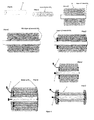
figure 1 schematically shows the different steps of the method of the invention, -
figure 2 schematically shows different cross sections ofhollow support 4 which can be used for manufacturing the outer electrode, -
figure 3 shows a chronoamperometric curve recorded when carrying out the electrodeposition of gold through the template of colloidal nanoparticles, in example 1, step e) of the process of the invention, -
figure 4 shows a top view image obtained by SEM (Scanning Electron Microscopy), of the structure obtained in step e) of the process of the invention, in example 1, -
figure 5 shows an image obtained by SEM, of the outer electrode obtained in example 1, in step f) but after having removed the glass capillary and the nickel and silver layers, -
figure 6 shows an image obtained by optical microscopy of the assembled inner and outer electrodes obtained in example 1, -
figure 7 shows cyclic voltammograms obtained with the inner electrode alone, the outer electrode alone and the miniaturized cell, obtained in example 1, in 0.5M H2SO4, -
figure 8 shows cyclic voltammograms obtained with the inner electrode alone, the outer electrode alone and the miniaturized cell, obtained in example 1, during oxygen reduction. - In the method of the invention, the inner electrode and the outer electrode are manufactured independently from each other.
- The outer electrode is made of a macroporous electron-conducting or semi-conducting material.
- The inner electrode can be made of a macroporous material or of a non macroporous material.
- The method for manufacturing the outer electrode, noted 2 in
figure 1 , is as follows. - The first step noted b) in
figure 1 , of the process of manufacture of theouter electrode 2 is to choose a hollow support, noted 4 infigure 1 , made of an electrically insulating material M6. - This
support 4, because hollow, has at least one internal cavity extending along the length of the support and each internal cavity defining a hollow channel. - Each hollow channel is intended to serve as casing for an inner electrode.
- This
support 4 may be a hollow cylinder having at least one hollow channel, or a hollow parallelepiped having at least one hollow channel. When thesupport 4 has one internal cavity, it is called "single channel support" and when thesupport 4 has more than one internal cavity, it is called "multi-channel support". Generally, the support used in the invention has an external diameter of from 100µm to 1mm and each channel has an internal diameter of from 10µm to 500µm The length of the support used in the invention is generally comprised between 1mm and 5cm. - When the
support 4 is a parallelepiped, the parallelepiped can have a square section or a rectangular section. - In the same manner, the internal hollow channel(s) may have a circular, square or rectangular section.
-
Figure 2 shows cross sections of single channel and multi-channel cylindrical supports which can be used. Infigure 2 , each channel is noted 8. - Because the inner electrode, noted 1 in
figure 1 , will be placed in one internal channel of the support, the dimension of this internal channel must be higher than the external dimension of theinner electrode 1. - The
support 4 is intended to be removed at the end of the manufacture of the miniaturized electrode cell according to the invention, this removal leaving a gap between theinner electrode 1 and the outer electrode noted 2 infigure 1 . - Accordingly, the thickness of the walls of the
support 4 must be equal to the width of the gap which is desired between theelectrodes - The
support 4 can be a capillary made of glass (soda-lime, borosilicate or aluminium silicate), quartz, or a hydrophilic polymer (PMMA). - Preferably, the
support 4 is a glass capillary having a total diameter of around 1mm and an inner diameter of around 300µm. - The second step, noted c) in
figure 1 , of manufacture of the outer electrode is to deposit on the external surface of the support 4 a layer of an electrically conducting material M2, by an electroless deposition method. Indeed, thesupport 4 being made of an electrically insulating material, it is necessary to deposit an electrically conducting material by an electroless deposition method in order to be able to then deposit a smoother and thicker layer by an electrodeposition method. - This layer of material M2 is a very thin layer having a thickness (less than 1 µm, and preferably a thickness comprised between 1 nm and 100 nm).
- The material M2 can be chosen among Ag, Ni, Cu, Au.
- Ag is preferred in the invention, as material M2.
- Ag may be deposited by chemical reduction of [Ag(NH3)2]+ ions contained in a Tollens' reagent with a glucose solution.
- The Tollens' reagent consists of a solution of silver nitrate and ammonia.
- Silver is preferred because it forms a "silver mirror" surface on the
support 4 which can be used straight-forward as a substrate for the deposition of cylindrical multilayered Langmuir-Blodgett films. - Indeed, the following step, noted d) in
figure 1 , of the method for manufacturing theouter electrode 2, according to the method of the invention, is to deposit on thesupport 4 coated with the layer of material M2, a template, noted 5 infigure 1 , of colloidal particles made of an electrically insulating material M3. - The
template 5 is formed of a number of layers of colloidal particles which has twice the thickness of the layer of electrically conducting material M5 wanted for forming theouter electrode 2. - Indeed, in this manner, the electro-deposition of the material M5 wanted for forming the outer electrode is homogeneous and there is no risk of overgrowing the template structure.
- The
template 5 is intended to be removed after the deposit of the material wanted for theouter electrode 2. - The removal of the
template 5 of colloidal particles will leave pores in the layer of the material M5 wanted for forming the outer electrode so that an electrode made of a macroporous material M5 is obtained. - After step d) of forming the
template 5 of colloidal particles, the next step of the process of the invention is to deposit, through thetemplate 5, a layer of an electrically conducting material M4 on the layer of electrically conducting material M2. This layer is necessary for stabilizing the M2 layer and allows the effective deposition of a smooth M5 layer afterwards. This layer has a thickness of between 1 and 100nm, preferably 20nm. - This step is noted e) in
figure 1 . - This step e) enables the homogeneous electro-deposition of the material wanted for forming the outer electrode through the
template 5. - The electrically conducting material M4 is chosen among Ni and Cr.
- Preferably, when the first layer of electrically conducting material M2 is a layer of Ag, and the second layer of electrically conducting material M4 is a layer of Ni.
- The electro-deposition of the material M5 is stopped when the layer L1 has the thickness wanted for the
outer electrode 2. - Then, in step noted f) in
figure 1 , the previously cited layer L1 of an electron conducting or semi-conducting material M5 (the material wanted for constituting the outer electrode) is deposited by an electro-deposition method through thetemplate 5. - Then, in step noted g) in
figure 1 , theinner electrode 1 which has been prepared after or before the preparation of the outer electrode, is introduced into the at least one internal hollow channel of the structure obtained in step noted f). - Then, the structure obtained in step g) is stabilized at its two open ends with an electrically insulating material M7, in a step noted h) in
figure 1 . - This material M7 must not be soluble in a solvent in which the materials M2, M3, M4, M6 present at this step as well as, when the inner electrode is made of a macroporous material M1, the material, M9 used for manufacturing such an inner electrode are soluble.
- Indeed, the material M7 must remain after the removing of the materials M2, M3 ,M4, M6 and M9 Indeed, the next step, noted i) in
figure 1 , of the method for manufacturing a miniaturized electrode cell of the invention is to remove the material M2 forming the first layer of electrically conducting material, the material M4 forming the second layer of electrically conducting material and the material M6 forming thesupport 4. - After this step, a miniaturized electrode cell consisting of two coaxial electrodes and an addressing wire, noted 7 in
figure 1 , is obtained. - The addressing
wire 7 is a wire for electrically addressing the electrodes. - But, the miniaturized electrode cell obtained by the method of the invention may consist of more than two electrodes. It can consist of up to 5 coaxial electrodes.
- For example, for obtaining a miniaturized electrode cell consisting of three coaxial electrodes, steps b) to g) are repeated before step h) of stabilizing the structure obtained in step g) and before step i) of removing the materials M2, M3, M4 and M6, the inner electrode being in that case, the first structure obtained after step f) of manufacturing a miniaturized electrode cell consisting of two coaxial electrodes.
- In the method of the invention, the
inner electrode 1 is preferably made of a macroporous material. In this latter case, theinner electrode 1 is preferably prepared by a method comprising the following steps: a1), a2), a3) and a4). - Step a1) is a step of providing a substrate S1 having the shape wanted for the
inner electrode 1. - This means that this substrate S1 should be a cylindric substrate, or a parallelepipedic substrate having a square or rectangular section.
- The substrate S1 is made of an electron conducting or semi-conducting material Mg, preferably the same material as the material M1, wanted for forming the
inner electrode 1. - In step a2), a template T1 of colloidal particles made of an electrically insulating material M9 is formed around the outer surface of the substrate S1.
- The substrate S1 may be a hollow substrate or a rod of material M8.
- Then, in step a3), a layer L1 of an electron conducting or semi-conducting material M1 is deposited on the surface of the substrate S1, by an electro-deposition method, through the colloidal particles of the template T1.
- Again, the template T1 has a height which is higher than the wanted thickness of the layer L1.
- As for the
outer electrode 2, the electro-deposition of the material M1 is stopped when the thickness of the layer L1 plus the thickness of the substrate S1, reach the dimensions wanted for the finalinner electrode 1. - Then, the material M9 is removed with a solvent in which the materials M1 and M8 are not soluble.
- However, the material M9 can also be eliminated after the
inner electrode 1 has been introduced into the internal cavity of the structure obtained in step f) of the preparation of the outer electrode and removed at the same times as the materials M2, M3, M4 and M6 used for preparing theouter electrode 2. - In that case, step i) is a step in which the material M9 forming the template T1 is also removed.
- In the method of the invention, the materials M1 and M5, i.e. the materials rendered macroporous which constitute the electrodes of the miniaturized electrode cell of the invention are independently from each other chosen among Pd, Ag, Cr, Au, Pt, Cu, Ni, Zn, an electron-conducting or semi-conducting polymer such as polypyrrole (PPy), polyaniline (PAni), polyacetylene, poly(3,4-ethylenedioxythiophene:sodium poly(styrene sulfonate) (PEDOT:PSS).
- Preferably the materials M1, M5 and M8 are Au.
- The materials forming the
hollow support 4, thetemplate 5 and the template T1, i.e. the materials M6, M3 and M9 are independently from each other chosen among SiO2, a glass or a plastic. - If they are made of plastic they are preferably made of polystyrene.
- Step a) of preparation of the
inner electrode 1 may be carried out before the first step noted b) of preparation of the outer electrode, or, after the step noted f) of preparation of the outer electrode. - Step h) of stabilizing the structure obtained in step g) is preferably a step of stabilizing the two ends with an epoxy resin or a silicon based adhesive which is liquid at ambient temperature and which is then hardened or reticulated.
- When the materials M3 and M9 are SiO2 and the material M6 is a glass which is preferred, and when the material M2 is Ag and the material M4 is Ni, then step i) comprises a step i1) of dissolving the materials M3, M6 and M9 with a solution of hydrofluoric acid, and a step i2) of dissolving the materials M2 and M4 with a solution of nitric acid or of sulfuric acid.
- It will clearly appear to the man skilled in the art that when, the
support 4 is a multi-channel support, the inner electrodes (macroporous or not) will have to be positioned in each channel. - With the method of the invention, the gap between the electrodes is tunable and can be higher than 100 µm.
- Thus, the invention also proposes a miniaturized electrode cell consisting of two to 5 coaxial electrodes (1, 2) having a thickness of from 1 to 50 µm made of identical or different conducting or semi-conducting macroporous materials and an addressing wire.
- The addressing wire connected to the
inner electrode 1 is advantageously the preexisting copper tape that was used to connect the template T1 to the potentiostat during the electro-deposition of the electron-conducting or semi-conducting material M1, during the preparation of the inner electrode. - Preparation of coaxial double electrode based on glass capillary approach.
- In this example, the inner electrode is made of a macroporous material. More precisely, the substrate S1 for preparing the inner electrode is a gold microwire ((d= 250 µm) and the
support 4 is a Thin Layer Chromatography (TLC) single-channel glass capillary with an outer diameter of 1150µm and an inner diameter of 280µm. - Gold microwire (d= 250 µm, AlfaAesar, purity 99.9%) has been cut into 3 cm long pieces that are straighten by slight rolling in between two microscope glass slides.
- TLC glass capillaries (HIRSCHMANN® LABORGERATE) were cut in 7 cm long pieces.
- In order to clean and hydrophilize the samples, gold microwires were immersed into "Piranha" solution two times for 10 minutes and subsequently rinsed with MilliQ water.
- Additionally, cleaned gold microwires were hydrophilized using UV/O3 for 20 min. just before deposition of silica particles (see subsection 4.3.).
- Prior the "Piranha" treatments, glass capillaries were degreased by 15 min. sonication in chloroform.
- "Piranha" solution was prepared by mixing concentrated sulfuric acid (co = 0,98 , Sigma Aldrich) with concentrated Hydrogen peroxide (ω=0,3, Sigma Aldrich) in volumetric ratio 75% v/v-25% v/v.
- After the cleaning step, samples have been firmly rinsed with MiliQ water and dried with compressed air.
- The degreased and pre-cleaned glass capillaries have been metallized by a thin silver coating. The metallization is based on the well known reduction of diaminesilver(I) ions by glucose in the presence of anionic surfactant (sodium-dodecyl sulphonate (SDS)).
- The composition and the procedure for the preparation of diaminesilver(I) reagent (i.e. Tollens' reagent) is given in Table 1.
Compound Concentration Volume/Mass Silver-nitrate 0.1M 70 ml Sodium-hydroxide 1M Added in a drops in silver-nitrate all until the precipitation of Ag2O was occurring Ammonia 25 % wt. Added in a drops until the Ag2O was completely dissolved SDS Added in a solid state to make the final concentration of 20 mM* 520 mg Glucose 20 % wt. 20 ml - *The first three compounds were mixed as described, and the SDS was added to the pre-measured 70 ml of obtained mixture. After adding SDS mixture was stirred until the SDS was completely dissolved.
- Table 1. Composition of the solution used for electroless silver metallization of glass capillaries. The components used for the preparation of Tollens' reagent are denoted in blue color.
- The glass capillaries were immersed in Tollens' solution which was preheated up to 70 °C. In the following step, the glucose solution was added at once and both components were shortly mixed by magnet stirrer.
- After the 3 min. metallization was complete and the metalized glass capillaries were firmly rinsed with MilliQ water.
- Metallized glass capillaries were used straightforward for the deposition of silica particles by Langmuir-Blodgett technique.
- Silica nanoparticles have been synthesized using well-known Stöber method based on hydrolysis of tetraethylorthosilicate (TEOS) in basic solution and polycondensation of the formed silicate acid.
- Synthesized silica nanoparticles have been covalently functionalized using a known coupling reaction with 3-aminopropyltriethoxysilane (APTES).
- The synthesis of silica beads has been performed in a two-step procedure at room temperature by controlled addition of a TEOS-absolute ethanol mixture (i.e. synthesis mixture), using a single-syringe pump system, into the three-necked flask that contained an absolute ethanol-water-ammonia (ω=0,25) solution (i.e. hydrolyzing solution). Set-up was equipped with stirring system and refrigerant.
- Silica seeds were prepared by adding TEOS directly in the hydrolyzing solution. The experimental conditions are listed in Table 2:
Table 2. Experimental condition for the synthesis of 300 nm silica "seeds" (first step). Data Value V(TEOS) 10 ml Hydrolyzing solution: V (ammonia) 30 ml V (abs. ethanol) 200 ml V (water) 50 ml Speed of the addition of synthesis solution TEOS was added at once in the hydrolyzing solution Time of synthesis 2 h 30 min. Speed of mixing 300 rpm Final diameter of synthesized silica nanoparticles 300 nm - The pre-synthesized 300 nm silica beads were used as a seeds for the synthesis of 600 nm silica particles (second step). Experimental conditions are shown in Table 3. The excess of ammonia present in the suspension of 300 nm seeds was sufficient enough to hydrolyze the TEOS that has been added in the second step of synthesis.
Table 3. Experimental condition for the synthesis of 300 nm silica particles from 300 nm silica "seeds". Data Value V (suspension of 300 nm silica beads) 181 ml Synthesis solution: V(TEOS) 45 ml V(abs. ethanol) 45 ml Hydrolyzing solution: 181 ml of the suspension of 300 nm silica seeds Speed of the addition of synthesis solution 8 ml/h Time of synthesis after the synthesis solution was added 12h Speed of mixing 300 rpm Final diameter of synthesized silica particles 600 nm - The surface of silica particles has been covalently modified with APTES.
- The amount of added APTES was 10 times larger than the calculated value in order to ensure good surface coverage of the silica beads.
- APTES was added into the original post synthetic mixture that contains silica nanoparticles. Mixture was stirred over night and heated next day at 80 °C for 1h to ensure good covalent binding of APTES.
- Calculation of the sufficient amount of APTES (given below) is based on the geometrical consideration that 2 APTES molecules covers 1 nm2 of the surface of silica particles and that density of silica beads is 2.2 g/cm3.
-





- Functionalized silica nanobeads were purified by rinsing with MilliQ water 10 times. Each rinsing cycle is followed by centrifugation in order to separate the supernatant from the bulk.
- Additionally, beads were purified using dialysis against MilliQ water in three separate segments. During the first two dialysis cycles MilliQ water was changed after the 2h, while for the last one the dialysis was carried-out over night.
- Colloidal crystal templates have been prepared using the Langmuir-Blodgett technique based on assembly of covalently functionalized silica nanoparticles.
- Silica nanoparticles (d=585 nm), used for the compression of Langmuir-Blodgett films, were previously sonicated for 10 minutes in order to avoid aggregation, washed 5 times with absolute ethanol and centrifuged each time to separate the supernatant from the nanoparticle deposit.
- Between two consecutive washing steps, silica nanoparticles were sonicated for a few minutes in order to enhance the efficiency of the washing procedure and disperse them in the bulk.
- After completion of washing procedure, silica nanoparticles were redispersed in the ethanol-chloroform mixture (20% v/v-80% v/v respectively). The solvents were added separately. The redespersion of silica beads after adding each solvent was followed by 5 min. of sonication.
- Freshly prepared suspensions of silica nanoparticles were immediately used for the preparation of Langmuir-Blodgett films.
- The compression of a monolayer of nanoparticles has been carried out on a LB trough (NIMA, type: 622).
- The Teflon-coated surface of the apparatus as well as the surface of the moveable barriers was cleaned with dichloromethane.
- Apparatus was filled with MilliQ water and dust contaminations were sucked out with a water pump. The suspension of silica nanoparticles was added onto the pre-cleaned water surface drop by drop with an interval of a few seconds between two consecutive adding.
- Gold microwires and pre-cleaned silver coated glass capillaries were attached to the dipping mechanism of the LB trough.
Table 4. Parameters for the compression of Langmuir-Blodgett film using 600 nm silica beads. Parameter Value Targeted surface tension 8 mN/m Speed up 1 mm/min Speed down 63 mm/min Barrier speed 29 cm2/min Programmed number of layers 30 - The device consists of two cylindrical and macroporous electrodes- the inner (macroporous gold microwire) and outer (mechanically stabilized macroporous film) electrodes. Both electrodes were prepared independently and the final device (which comprises both electrodes) was assembled in the last step of the fabrication.
- The inner macroporous electrode has been prepared by potentiostatic electrodeposition of gold using a commercially available gold electroplating solution (ECF63, Metalor).
- The electrodeposition was performed in a conventional three-electrode system, consisting of working (colloidal-crystal modified gold microwire), reference (Ag/AgCl (3M NaCl)) and cylindrical counter (Pt) electrodes. The gold electrodeposition was performed at the electrode potential of -0.66 V vs Ag/AgCl (3M NaCl).
- The length of the colloidal-crystal template immersed into the electroplating solution was dependent on the quality of the template along the wire.
- The precise positioning of the sample inside the electrochemical cell has been accomplished by micro-positioning system built on purpose.
- The inner electrode was electrically addressed by means of pre-existing copper tape that was used to connect the silica-template covered gold microwire to the potentiostat during the electrodeposition of gold (see subsection 5.1.).
- The colloidal crystal assembled on the surface of the metallized glass capillary, served as a template for the electrodeposition of gold.
- Prior to the electrodeposition of gold, the thin silver layer was stabilized by a short (3 min.) potentiostatic electrodeposition of a nickel layer. The nickel layer was electrodeposited using a commercially available nickel electroplating solution (semi-bright nickel solution, AlfaAesar) at -0.9 V vs Ag/AgCl (3M NaCl).
- After the electrodeposition of the nickel layer, the gold/silica composite structure was obtained by electrodeposition of gold (ECF63, Metalor) at -0.75 V vs Ag/AgCl (3M NaCl) through the silica based template until the desired number of layers was infiltrated.
- As can be seen from
figure 3 , the chromoamperometric curve recorded during this electrodeposition of gold shows well pronounced oscillations which indicate the good quality of the colloidal template and thus the homogeneity of the silver coating underneath. This confirmed by SEM characterization, shown infigure 4 , where homogeneously distributed pressure observed similar to what was observed in case of the macroporous gold microwire prepared as inner electrode. - The outer electrode was electrically addressed by means of a gold microwire (50 µm). The gold microwire was attached on the surface of outer electrode by a droplet of conductive silver paint (Agar silver paint, Agar). In the following step the structure was heated by an air-gun in order to harden the paint quickly by evaporating the solvent.
- Silver and nickel layers were removed by etching in 24% wt. nitric-acid (Sigma Aldrich) overnight. This step facilitates the subsequent etching of the glass capillary (see subsection 5.7.) since once the underlying silver/nickel layer (that may act as a protective shell) is removed, the glass capillary is easily accessible to hydrofluoric acid.
-
Figure 5 shows the topology of the macroporous cylinder obtained at this step, removed from the glass capillary. - After the inner and the outer electrode were assembled into a device, the whole structure was sealed at its extremities by using the two-component epoxy glue (Quick Set Epoxy Adhesive, RS).
- Once the full structure is assembled and the two-component epoxy glue is completely cured, the assembled device is etched with concentrated (48% wt.) HF (Sigma Aldrich) over the 5-6 hours. During the etching, the silica beads were removed in the first few seconds while the etching of the glass capillary required longer time (5-6 h).
- The final macroporous coaxial double electrode device was kept in MilliQ water.
-
Figure 6 shows the obtained miniaturized cell. - The centrally positioned macroporous gold wire is the inner electrode and the macroporous cylinder is the outer electrode.
- The inter-electrode distance is 450 µm.
- Final confirmation of the structural stability of the coaxial macroporous system with two independently addressable electrodes is obtained by cyclic voltammetry (CV).
- CV record was performed using a three electrode system with working electrode (coaxial sample), reference electrode (sat. Ag/AgCl) and counter electrode (Pt cylinder). The experimental conditions are given by Table 5.
Table 5 Parameter Value Scan rate 100 mV/s Potential window 0 V to 1.6 V Supporting electrolyte 0.1 M sulphuric acid Deaeration of the electrolyte Solution was purged with pure argon for 10 min. - Charge that corresponds to the characteristic cathodic peak (stripping peak) obtained from cyclic voltammograms is directly proportional to the active surface of the electrode.
- In case that the formation of short circuits is successfully avoided the calculated charges are different when the two independent coaxial porous electrodes are connected separately. In the control experiment, by connecting the two coaxial porous electrodes together, a cumulative charge for both electrodes is obtained.
- The electrode potential is cycled for at least 20 times during the experiment until the current reaches its constant value.
- During the measurements the position of the sample is fixed using a micropositioning system built on purpose.
-
Figure 7 shows the CV obtained for the inner electrode (curve noted A), the outer electrode (curve noted B), and the miniaturized cell obtained in § 5.7 above (curve noted C), and recorded in 0.5M H2SO4. Calculated electrode active surface areas for the inner and outer electrode as well as for the short-circuit miniaturized cell are 3.49 cm2 (31 half-layer), 20.77 cm2 (25 half-layer), and 24.56 cm2 respectively. - To investigate the electrochemical functionality of the macroporous coaxial architecture with respect to simple redox couples, cyclic-voltammetry experiments were performed in oxygen saturated sulfuric acid solution. Similar to what was described in subsection 5.8. independently addressable inner and outer macroproous electrodes were connected independently and the cyclic-voltammograms were recorded. The experimental protocol is given by Table 6.
Table 6 Parameter Value Electrolyte 50 mM sulfuric acid Redox probe Oxygen dissolved in 50 mM sulfuric acid Scan rate 5 mV/s Potential window -0.35 V - +0.4V -
Figure 7 shows the obtained cyclic voltamograms. Infigure 7 , curve noted A represents the cyclic voltamogram obtained with the inner electrode connected independently, curve noted B represents the cyclic voltamogram obtained with the outer electrode connected independently and curve noted C represents the cyclic voltamogram obtained with the miniaturized cell obtained in § 5.7 above. - As can be seen from
figure 8 the individual electrodes exhibit an onset of oxygen reduction current around +0.3 V which is correlated to the respective active surface areas. External short-circuiting of the inner and outer electrode leads to a current which corresponds to the sum of the individual currents.
Claims (17)
- A method for manufacturing a miniaturized electrode cell consisting of coaxial electrodes (1,2), the method comprising the following steps:a) preparing at least one inner electrode (1) made of an electron conducting or semi-conducting material M1,b) providing a hollow support (4) made of an electrically insulating material M6, this support (4) having at least one internal hollow channel, the dimensions of the at least one internal hollow channel being higher than the external dimensions of the inner electrode (1) and the thickness of the walls of this support (4) being at least equal to the width of the gap which is desired between the electrodes (1, 2),c) depositing on the external surface of the support (4) a layer of an electrically conducting material M2, by an electroless deposition method,d) forming a template (5) of colloidal particles made of an electrically insulating material M3, on the layer of electrically conducting material M2 deposited in step c),e) depositing a layer of an electrically conducting material M4 on the layer of electrically conducting material M2, through the template (5) by an electro-deposition method,f) depositing a layer L1 of an electron conducting or semi-conducting material M5 on the layer of electrically conducting material M4 by an electro-deposition method , through the template (5), this layer L1 having a thickness equal to the thickness of the outer electrode (2) to be obtained,g) introducing the at least one inner electrode (1) into the at least one internal hollow channel of the structure obtained in step f),h) stabilizing the structure obtained in step g) at its two open ends with an electrically insulating material M7 which is not soluble in a solvent in which the materials M2, M3, M4, and M6 are soluble,i) removing the materials M2, M3, M4 and M6, and
optionally repeating steps b) to g) at least one time, the structure obtained after each step g) constituting the at least one inner electrode to be introduced in the at least one internal hollow channel of each structure obtained in step f). - The method according to claim 1, wherein the at least one inner electrode is made of a macroporous electron conducting or semi-conducting material M1 and step a) comprises the following steps:a1) providing a substrate S1 having the shape wanted for the inner electrode (1) and made of an electron conducting or semi-conducting material M8,a2) forming a template T1 of colloidal particles made of an electrically insulating material M9,a3) depositing a layer L1 of an electron conducting or semi-conducting material M1 on the surface of the substrate S1 by an electro-deposition method, through the colloidal particles of the template T1, the substrate S1 coated with the layer L1 having the shape and the external dimensions wanted for the inner electrode (1),a4) removing the material M9 with a solvent in which the material M1 is not soluble.
- The method according to claim 1 or 2, wherein the materials M1, M5 and M8 are independently from each other chosen among Pd, Ag, Cr, Au, Pt, Cu, Ni, Zn, polypyrrole (PPy), polyaniline (PAni), polyacetylene, poly(3,4-ethylenedioxythiophene:sodium poly(styrene sulfonate) (PEDOT : PSS), preferably the materials M1, M5 and M8 are Au.
- The method according to anyone of the preceding claims, wherein the materials M6, M3 and M9 are independently from each other chosen among SiO2, a glass or a plastic which is preferably polystyrene.
- The method according to anyone of the preceding claims, wherein the materials M2 and M4 are independently from each other chosen among Ag, Ni, Cr.
- The method according to anyone of the preceding claims, wherein the material M2 is Ag and the material M4 is Ni.
- The method according to anyone of the preceding claims, wherein step a) is carried out after step f).
- The method according to anyone of the preceding claims, wherein step h) is a step of stabilizing the two ends of the structure obtained in step g) with an epoxy resin or a silicon based adhesive which is then hardened or reticulated.
- The method according to anyone of the preceding claims, wherein the materials M3 and M9 are SiO2, the material M6 is a glass, the material M2 is Ag, and the material M4 is Ni, and wherein step i) comprises the following steps:i1) dissolving the materials M3, M6 and M9 with a solution of hydrofluoric acid, andi2) dissolving the materials M2 and M4 with a solution of nitric acid or sulfuric acid.
- The method according to anyone of the preceding claims, wherein the support (4) and the substrate S1 are cylinders.
- The method according to anyone of claims 1 to 9, wherein the support (4) and the substrate S1 are parallelepipeds with a square or rectangular section.
- The method according to anyone of the preceding claims, wherein the support (4) is a single channel support.
- The method according to anyone of the claims 1-11, wherein the support (4) is a multi-channel support.
- A miniaturized electrochemical cell consisting of:- from 2 to 10, preferentially from 2 to 5, coaxial electrodes (1, 2) having a thickness of from 1 to 50 µm made of identical or different conducting or semi-conducting material M1 and macroporous material M5, the inter-distance between each electrode being higher than 100 µm, and- an addressing wire (7).
- A miniaturized electrochemical cell according to claim 14, wherein the materials M1 and M5 are independently from each other chosen among Pd, Ag, Cr, Au, Pt, Cu, Ni, Zn, polypyrrole (PPy), polyaniline (PAni), polyacetylene, poly(3,4-ethylenedioxythiophene:sodium poly(styrene sulfonate) (PEDOT : PSS), preferably the materials M1 and M5 are Au.
- The miniaturized electrochemical cell according to claim 14 or 15, wherein the electrodes (1, 2) have a cylinder shape.
- A miniaturized electrochemical cell, wherein the electrodes (1, 2) have a parallelepiped shape.
Priority Applications (6)
| Application Number | Priority Date | Filing Date | Title |
|---|---|---|---|
| EP15306180.9A EP3121875A1 (en) | 2015-07-20 | 2015-07-20 | Method for manufacturing a miniaturized electrochemical cell and a miniaturized electrochemical cell |
| PCT/IB2016/053868 WO2017013506A1 (en) | 2015-07-20 | 2016-06-29 | Method for manufacturing a miniaturized electrochemical cell and a miniaturized electrochemical cell |
| US15/741,845 US10608238B2 (en) | 2015-07-20 | 2016-06-29 | Method for manufacturing a miniaturized electrochemical cell and a miniaturized electrochemical cell |
| JP2018500322A JP6935387B2 (en) | 2015-07-20 | 2016-06-29 | Methods for manufacturing miniaturized electrochemical cells and miniaturized electrochemical cells |
| CA2991274A CA2991274C (en) | 2015-07-20 | 2016-06-29 | Method for manufacturing a miniaturized electrochemical cell and a miniaturized electrochemical cell |
| EP16735710.2A EP3326222A1 (en) | 2015-07-20 | 2016-06-29 | Method for manufacturing a miniaturized electrochemical cell and a miniaturized electrochemical cell |
Applications Claiming Priority (1)
| Application Number | Priority Date | Filing Date | Title |
|---|---|---|---|
| EP15306180.9A EP3121875A1 (en) | 2015-07-20 | 2015-07-20 | Method for manufacturing a miniaturized electrochemical cell and a miniaturized electrochemical cell |
Publications (1)
| Publication Number | Publication Date |
|---|---|
| EP3121875A1 true EP3121875A1 (en) | 2017-01-25 |
Family
ID=53773398
Family Applications (2)
| Application Number | Title | Priority Date | Filing Date |
|---|---|---|---|
| EP15306180.9A Withdrawn EP3121875A1 (en) | 2015-07-20 | 2015-07-20 | Method for manufacturing a miniaturized electrochemical cell and a miniaturized electrochemical cell |
| EP16735710.2A Withdrawn EP3326222A1 (en) | 2015-07-20 | 2016-06-29 | Method for manufacturing a miniaturized electrochemical cell and a miniaturized electrochemical cell |
Family Applications After (1)
| Application Number | Title | Priority Date | Filing Date |
|---|---|---|---|
| EP16735710.2A Withdrawn EP3326222A1 (en) | 2015-07-20 | 2016-06-29 | Method for manufacturing a miniaturized electrochemical cell and a miniaturized electrochemical cell |
Country Status (4)
| Country | Link |
|---|---|
| US (1) | US10608238B2 (en) |
| EP (2) | EP3121875A1 (en) |
| JP (1) | JP6935387B2 (en) |
| WO (1) | WO2017013506A1 (en) |
Cited By (1)
| Publication number | Priority date | Publication date | Assignee | Title |
|---|---|---|---|---|
| FR3063443A1 (en) * | 2017-03-06 | 2018-09-07 | Universite de Bordeaux | NANOSTRUCTURE POLYMERIC FILMS AND PROCESS FOR THEIR PREPARATION |
Families Citing this family (1)
| Publication number | Priority date | Publication date | Assignee | Title |
|---|---|---|---|---|
| CN115775883B (en) * | 2023-02-13 | 2023-06-02 | 四川富临新能源科技有限公司 | Surface modification method of lithium iron phosphate positive electrode material |
Citations (3)
| Publication number | Priority date | Publication date | Assignee | Title |
|---|---|---|---|---|
| WO2005055265A2 (en) * | 2003-11-26 | 2005-06-16 | The Penn State Research Foundation | Idt electroded piezoelectric diaphragms |
| WO2010124258A2 (en) * | 2009-04-24 | 2010-10-28 | Old Dominion University Research Foundation | Multiple walled nested coaxial nanostructures |
| CN104409683A (en) * | 2014-05-31 | 2015-03-11 | 福州大学 | Method for preparing side-by-side cathode and anode lithium ion battery based on coaxial 3D printing technology |
Family Cites Families (5)
| Publication number | Priority date | Publication date | Assignee | Title |
|---|---|---|---|---|
| KR101159226B1 (en) * | 2009-09-30 | 2012-06-25 | 국립대학법인 울산과학기술대학교 산학협력단 | Negative active material for rechargeable lithium battery, method of preparing the same, and rechargeable lithium battery including the same |
| US8268382B2 (en) * | 2010-07-12 | 2012-09-18 | Medtronic Vascular, Inc. | Method of making a stent with hollow struts |
| JP5682698B2 (en) * | 2013-12-25 | 2015-03-11 | セイコーエプソン株式会社 | Lithium iodine battery, medical equipment |
| US20160013340A1 (en) * | 2014-04-21 | 2016-01-14 | Northwestern University | Coaxial lithography |
| EP2991136A1 (en) | 2014-08-29 | 2016-03-02 | Centre National De La Recherche Scientifique | Method for manufacturing a miniaturized electrochemical cell |
-
2015
- 2015-07-20 EP EP15306180.9A patent/EP3121875A1/en not_active Withdrawn
-
2016
- 2016-06-29 US US15/741,845 patent/US10608238B2/en active Active
- 2016-06-29 EP EP16735710.2A patent/EP3326222A1/en not_active Withdrawn
- 2016-06-29 WO PCT/IB2016/053868 patent/WO2017013506A1/en not_active Ceased
- 2016-06-29 JP JP2018500322A patent/JP6935387B2/en active Active
Patent Citations (3)
| Publication number | Priority date | Publication date | Assignee | Title |
|---|---|---|---|---|
| WO2005055265A2 (en) * | 2003-11-26 | 2005-06-16 | The Penn State Research Foundation | Idt electroded piezoelectric diaphragms |
| WO2010124258A2 (en) * | 2009-04-24 | 2010-10-28 | Old Dominion University Research Foundation | Multiple walled nested coaxial nanostructures |
| CN104409683A (en) * | 2014-05-31 | 2015-03-11 | 福州大学 | Method for preparing side-by-side cathode and anode lithium ion battery based on coaxial 3D printing technology |
Non-Patent Citations (1)
| Title |
|---|
| KARAJIC ET AL.: "Bottom-up Generation of Miniaturized Coaxial Double Electrodes with Tunable Porosity", ADVANCED MATERIALS INTERFACES, vol. 2, no. 12, 6 July 2015 (2015-07-06), pages 1 - 5, XP002751090, DOI: 10.1002 * |
Cited By (2)
| Publication number | Priority date | Publication date | Assignee | Title |
|---|---|---|---|---|
| FR3063443A1 (en) * | 2017-03-06 | 2018-09-07 | Universite de Bordeaux | NANOSTRUCTURE POLYMERIC FILMS AND PROCESS FOR THEIR PREPARATION |
| WO2018162374A1 (en) * | 2017-03-06 | 2018-09-13 | Université De Bordeaux | Nanostructured polymer films and method for preparing same |
Also Published As
| Publication number | Publication date |
|---|---|
| WO2017013506A1 (en) | 2017-01-26 |
| CA2991274A1 (en) | 2017-01-26 |
| US10608238B2 (en) | 2020-03-31 |
| JP2018532223A (en) | 2018-11-01 |
| EP3326222A1 (en) | 2018-05-30 |
| US20180205070A1 (en) | 2018-07-19 |
| JP6935387B2 (en) | 2021-09-15 |
Similar Documents
| Publication | Publication Date | Title |
|---|---|---|
| EP2991136A1 (en) | Method for manufacturing a miniaturized electrochemical cell | |
| Wang et al. | Inkjet printing of conductive patterns and supercapacitors using a multi-walled carbon nanotube/Ag nanoparticle based ink | |
| CN104466085B (en) | Lithium ion battery | |
| DE69731976T2 (en) | METAL OXYNITRIDE WITH HIGH SPECIFIC SURFACE FOR STORING ELECTRICAL ENERGY | |
| US10745821B2 (en) | Dissymetric particles (Janus particles) and their method of synthesis by bipolar electrochemistry | |
| WO2012138302A1 (en) | Multilayer film comprising metal nanoparticles and a graphene-based material and method of preparation thereof | |
| US10944129B2 (en) | Conducting polymers | |
| Purkait et al. | All-porous heterostructure of reduced graphene oxide–polypyrrole–nanoporous gold for a planar flexible supercapacitor showing outstanding volumetric capacitance and energy density | |
| WO2017093074A1 (en) | Method for producing a silicon-based porous electrode for a battery, in particular a lithium-ion battery | |
| US20110045351A1 (en) | High-Power Nanoscale Cathodes for Thin-Film Microbatteries | |
| Lin et al. | Soft gold nanowire sponges for strain-insensitive conductors, wearable energy storage and catalytic converters | |
| US10608238B2 (en) | Method for manufacturing a miniaturized electrochemical cell and a miniaturized electrochemical cell | |
| US20150162597A1 (en) | Methods for producing textured electrode based energy storage devices | |
| Divya et al. | Nanomaterials at liquid/liquid interfaces-A review | |
| CA2991274C (en) | Method for manufacturing a miniaturized electrochemical cell and a miniaturized electrochemical cell | |
| KR101710808B1 (en) | An electrode for energy storage devide and method for preparing the same | |
| Tang et al. | Directionally electrodeposited gold nanoparticles into honeycomb macropores and their surface-enhanced Raman scattering | |
| Das et al. | Electrophoretic Deposition and Inkjet Printing as Promising Fabrication Routes to Make Flexible Rechargeable Cells and Supercapacitors | |
| WO2022063531A1 (en) | Electrochemical process for forming a solid electrolyte |
Legal Events
| Date | Code | Title | Description |
|---|---|---|---|
| PUAI | Public reference made under article 153(3) epc to a published international application that has entered the european phase |
Free format text: ORIGINAL CODE: 0009012 |
|
| AK | Designated contracting states |
Kind code of ref document: A1 Designated state(s): AL AT BE BG CH CY CZ DE DK EE ES FI FR GB GR HR HU IE IS IT LI LT LU LV MC MK MT NL NO PL PT RO RS SE SI SK SM TR |
|
| AX | Request for extension of the european patent |
Extension state: BA ME |
|
| STAA | Information on the status of an ep patent application or granted ep patent |
Free format text: STATUS: THE APPLICATION IS DEEMED TO BE WITHDRAWN |
|
| 18D | Application deemed to be withdrawn |
Effective date: 20170726 |