EP3121640A1 - Autostereoscopic display device - Google Patents
Autostereoscopic display device Download PDFInfo
- Publication number
- EP3121640A1 EP3121640A1 EP16183300.9A EP16183300A EP3121640A1 EP 3121640 A1 EP3121640 A1 EP 3121640A1 EP 16183300 A EP16183300 A EP 16183300A EP 3121640 A1 EP3121640 A1 EP 3121640A1
- Authority
- EP
- European Patent Office
- Prior art keywords
- pixels
- pixel
- display
- sub
- resolution
- Prior art date
- Legal status (The legal status is an assumption and is not a legal conclusion. Google has not performed a legal analysis and makes no representation as to the accuracy of the status listed.)
- Granted
Links
Images



Classifications
-
- H—ELECTRICITY
- H04—ELECTRIC COMMUNICATION TECHNIQUE
- H04N—PICTORIAL COMMUNICATION, e.g. TELEVISION
- H04N13/00—Stereoscopic video systems; Multi-view video systems; Details thereof
- H04N13/30—Image reproducers
- H04N13/302—Image reproducers for viewing without the aid of special glasses, i.e. using autostereoscopic displays
- H04N13/305—Image reproducers for viewing without the aid of special glasses, i.e. using autostereoscopic displays using lenticular lenses, e.g. arrangements of cylindrical lenses
-
- G—PHYSICS
- G02—OPTICS
- G02B—OPTICAL ELEMENTS, SYSTEMS OR APPARATUS
- G02B30/00—Optical systems or apparatus for producing three-dimensional [3D] effects, e.g. stereoscopic images
- G02B30/20—Optical systems or apparatus for producing three-dimensional [3D] effects, e.g. stereoscopic images by providing first and second parallax images to an observer's left and right eyes
- G02B30/26—Optical systems or apparatus for producing three-dimensional [3D] effects, e.g. stereoscopic images by providing first and second parallax images to an observer's left and right eyes of the autostereoscopic type
- G02B30/27—Optical systems or apparatus for producing three-dimensional [3D] effects, e.g. stereoscopic images by providing first and second parallax images to an observer's left and right eyes of the autostereoscopic type involving lenticular arrays
-
- G—PHYSICS
- G02—OPTICS
- G02B—OPTICAL ELEMENTS, SYSTEMS OR APPARATUS
- G02B30/00—Optical systems or apparatus for producing three-dimensional [3D] effects, e.g. stereoscopic images
- G02B30/20—Optical systems or apparatus for producing three-dimensional [3D] effects, e.g. stereoscopic images by providing first and second parallax images to an observer's left and right eyes
- G02B30/26—Optical systems or apparatus for producing three-dimensional [3D] effects, e.g. stereoscopic images by providing first and second parallax images to an observer's left and right eyes of the autostereoscopic type
- G02B30/27—Optical systems or apparatus for producing three-dimensional [3D] effects, e.g. stereoscopic images by providing first and second parallax images to an observer's left and right eyes of the autostereoscopic type involving lenticular arrays
- G02B30/29—Optical systems or apparatus for producing three-dimensional [3D] effects, e.g. stereoscopic images by providing first and second parallax images to an observer's left and right eyes of the autostereoscopic type involving lenticular arrays characterised by the geometry of the lenticular array, e.g. slanted arrays, irregular arrays or arrays of varying shape or size
-
- G—PHYSICS
- G09—EDUCATION; CRYPTOGRAPHY; DISPLAY; ADVERTISING; SEALS
- G09G—ARRANGEMENTS OR CIRCUITS FOR CONTROL OF INDICATING DEVICES USING STATIC MEANS TO PRESENT VARIABLE INFORMATION
- G09G3/00—Control arrangements or circuits, of interest only in connection with visual indicators other than cathode-ray tubes
- G09G3/20—Control arrangements or circuits, of interest only in connection with visual indicators other than cathode-ray tubes for presentation of an assembly of a number of characters, e.g. a page, by composing the assembly by combination of individual elements arranged in a matrix no fixed position being assigned to or needed to be assigned to the individual characters or partial characters
- G09G3/34—Control arrangements or circuits, of interest only in connection with visual indicators other than cathode-ray tubes for presentation of an assembly of a number of characters, e.g. a page, by composing the assembly by combination of individual elements arranged in a matrix no fixed position being assigned to or needed to be assigned to the individual characters or partial characters by control of light from an independent source
- G09G3/36—Control arrangements or circuits, of interest only in connection with visual indicators other than cathode-ray tubes for presentation of an assembly of a number of characters, e.g. a page, by composing the assembly by combination of individual elements arranged in a matrix no fixed position being assigned to or needed to be assigned to the individual characters or partial characters by control of light from an independent source using liquid crystals
- G09G3/3607—Control arrangements or circuits, of interest only in connection with visual indicators other than cathode-ray tubes for presentation of an assembly of a number of characters, e.g. a page, by composing the assembly by combination of individual elements arranged in a matrix no fixed position being assigned to or needed to be assigned to the individual characters or partial characters by control of light from an independent source using liquid crystals for displaying colours or for displaying grey scales with a specific pixel layout, e.g. using sub-pixels
-
- G—PHYSICS
- G09—EDUCATION; CRYPTOGRAPHY; DISPLAY; ADVERTISING; SEALS
- G09G—ARRANGEMENTS OR CIRCUITS FOR CONTROL OF INDICATING DEVICES USING STATIC MEANS TO PRESENT VARIABLE INFORMATION
- G09G3/00—Control arrangements or circuits, of interest only in connection with visual indicators other than cathode-ray tubes
- G09G3/20—Control arrangements or circuits, of interest only in connection with visual indicators other than cathode-ray tubes for presentation of an assembly of a number of characters, e.g. a page, by composing the assembly by combination of individual elements arranged in a matrix no fixed position being assigned to or needed to be assigned to the individual characters or partial characters
- G09G3/34—Control arrangements or circuits, of interest only in connection with visual indicators other than cathode-ray tubes for presentation of an assembly of a number of characters, e.g. a page, by composing the assembly by combination of individual elements arranged in a matrix no fixed position being assigned to or needed to be assigned to the individual characters or partial characters by control of light from an independent source
- G09G3/36—Control arrangements or circuits, of interest only in connection with visual indicators other than cathode-ray tubes for presentation of an assembly of a number of characters, e.g. a page, by composing the assembly by combination of individual elements arranged in a matrix no fixed position being assigned to or needed to be assigned to the individual characters or partial characters by control of light from an independent source using liquid crystals
- G09G3/3611—Control of matrices with row and column drivers
- G09G3/3648—Control of matrices with row and column drivers using an active matrix
-
- H—ELECTRICITY
- H04—ELECTRIC COMMUNICATION TECHNIQUE
- H04N—PICTORIAL COMMUNICATION, e.g. TELEVISION
- H04N13/00—Stereoscopic video systems; Multi-view video systems; Details thereof
- H04N13/30—Image reproducers
- H04N13/302—Image reproducers for viewing without the aid of special glasses, i.e. using autostereoscopic displays
- H04N13/317—Image reproducers for viewing without the aid of special glasses, i.e. using autostereoscopic displays using slanted parallax optics
-
- H—ELECTRICITY
- H04—ELECTRIC COMMUNICATION TECHNIQUE
- H04N—PICTORIAL COMMUNICATION, e.g. TELEVISION
- H04N13/00—Stereoscopic video systems; Multi-view video systems; Details thereof
- H04N13/30—Image reproducers
- H04N13/324—Colour aspects
-
- H—ELECTRICITY
- H04—ELECTRIC COMMUNICATION TECHNIQUE
- H04N—PICTORIAL COMMUNICATION, e.g. TELEVISION
- H04N13/00—Stereoscopic video systems; Multi-view video systems; Details thereof
- H04N13/30—Image reproducers
- H04N13/349—Multi-view displays for displaying three or more geometrical viewpoints without viewer tracking
- H04N13/351—Multi-view displays for displaying three or more geometrical viewpoints without viewer tracking for displaying simultaneously
-
- H—ELECTRICITY
- H04—ELECTRIC COMMUNICATION TECHNIQUE
- H04N—PICTORIAL COMMUNICATION, e.g. TELEVISION
- H04N13/00—Stereoscopic video systems; Multi-view video systems; Details thereof
- H04N13/30—Image reproducers
- H04N13/398—Synchronisation thereof; Control thereof
-
- G—PHYSICS
- G09—EDUCATION; CRYPTOGRAPHY; DISPLAY; ADVERTISING; SEALS
- G09G—ARRANGEMENTS OR CIRCUITS FOR CONTROL OF INDICATING DEVICES USING STATIC MEANS TO PRESENT VARIABLE INFORMATION
- G09G2320/00—Control of display operating conditions
- G09G2320/02—Improving the quality of display appearance
- G09G2320/0233—Improving the luminance or brightness uniformity across the screen
-
- H—ELECTRICITY
- H04—ELECTRIC COMMUNICATION TECHNIQUE
- H04N—PICTORIAL COMMUNICATION, e.g. TELEVISION
- H04N2213/00—Details of stereoscopic systems
- H04N2213/001—Constructional or mechanical details
Definitions
- This invention relates to an autostereoscopic display device which comprises a display panel having an array of display pixels, and an arrangement for directing different views to different physical locations.
- a known autostereoscopic display device comprises a two dimensional emissive liquid crystal display panel having a row and column array of display pixels acting as an image forming means to produce a display.
- An array of elongate lenses extending parallel to one another overlies the display pixel array and acts as a view forming means. These are known as "lenticular lenses”. Outputs from the display pixels are projected through these lenticular lenses, which function to modify the directions of the outputs.
- the lenticular lenses are provided as a sheet of lens elements, each of which comprises an elongate semi-cylindrical lens element.
- the lenticular lenses extend in the column direction of the display panel, with each lenticular lens overlying a respective group of two or more adjacent columns of display pixels.
- Each lenticular lens can be associated with two columns of display pixels to enable a user to observe a single stereoscopic image. Instead, each lenticular lens can be associated with a group of three or more adjacent display pixels in the row direction. Corresponding columns of display pixels in each group are arranged appropriately to provide a vertical slice from a respective two dimensional sub-image. As a user's head is moved from left to right a series of successive, different, stereoscopic views are observed creating, for example, a look-around impression.
- the above described autostereoscopic display device produces a display having good levels of brightness.
- one problem associated with the device is that the views projected by the lenticular sheet are separated by dark zones caused by "imaging" of the non-emitting black matrix which typically defines the display pixel array. These dark zones are readily observed by a user as brightness non-uniformities in the form of dark vertical bands spaced across the display. The bands move across the display as the user moves from left to right and the pitch of the bands changes as the user moves towards or away from the display.
- Another problem is that the vertical lens result in a much greater reduction in resolution in the horizontal direction than in the vertical direction.
- display panels are based on a matrix of pixels that are square in shape.
- the pixels are divided into sub-pixels.
- each pixel is divided into 3 sub-pixels, transmitting or emitting red (R), green (G) and blue (B) light, respectively.
- Sub-pixels of equal colour are typically arranged in columns.
- WO2010/070564 discloses an arrangement in which the lens pitch and lens slant are selected in such a way as to provide an improved pixel layout in the views created by the lenticular array, in terms of spacing of colour sub-pixels, and uniformity of colour density. This case relates to the arrangement of the grid of pixels forming the 3D image, rather than the individual pixels.
- the invention concerns the shape of the individual pixels forming the 3D image.
- WO 2010/070564 discloses an autostereoscopic display with slanted lenticular lenses wherein a particular lens pitch is selected to achieve a uniform and regular distribution of 3D pixels.
- an autostereoscopic display device comprising:
- the invention provides a design space in which the 3D pixels can be designed to have an equal aspect ratio resolution as the underlying display panel.
- the design space offers good designs for high resolution panels such as Super Hi-Vision (SHV) displays.
- SHV Super Hi-Vision
- the 3D views will always have a lower spatial resolution than the underlying panel.
- the combination of lens pitch and slant angle take account of the reduction in resolution, the number of colour sub-pixels of the 2D display and the desired aspect ratio of the 3D pixels to be formed by the lens arrangement.
- the reduction factor represents the number of native 2D pixels there are per 3D pixel. Thus, the reduction factor is greater than 1.
- Each pixel of the display can comprise a striped RGB pixel with red green and blue sub-pixels each extending in the column direction and arranged side by side.
- each pixel of the display comprises a striped RGBY pixel with red green blue and yellow sub-pixels each extending in the column direction and arranged side by side.
- Other pixel configurations can also be used.
- the invention provides a lenticular autostereoscopic display device with a particular design of lenticular array (slant angle and preferably also lens pitch) to optimise the quality of the views provided to the user.
- the invention enables pitch and slant angles to be optimised to achieve 3D pixels with a similar aspect ratio as the underlying pixels. In practise this usually means that the invention leads to square or near square 3D pixels.
- Figure 1 is a schematic perspective view of a known multi-view autostereoscopic display device 1.
- the known device 1 comprises a liquid crystal display panel 3 of the active matrix type that acts as an image forming means to produce the display.
- the display panel 3 has an orthogonal array of display pixels 5 arranged in rows and columns. For the sake of clarity, only a small number of display pixels 5 are shown in Figure 1 . In practice, the display panel 3 might comprise about one thousand rows and several thousand columns of display pixels 5.
- the structure of the liquid crystal display panel 3 is entirely conventional.
- the panel 3 comprises a pair of spaced transparent glass substrates, between which an aligned twisted nematic or other liquid crystal material is provided.
- the substrates carry patterns of transparent indium tin oxide (ITO) electrodes on their facing surfaces.
- Polarising layers are also provided on the outer surfaces of the substrates.
- Each display pixel 5 comprises opposing electrodes on the substrates, with the intervening liquid crystal material therebetween.
- the shape and layout of the display pixels 5 are determined by the shape and layout of the electrodes and a black matrix arrangement provided on the front of the panel 3.
- the display pixels 5 are regularly spaced from one another by gaps.
- Each display pixel 5 is associated with a switching element, such as a thin film transistor (TFT) or thin film diode (TFD).
- TFT thin film transistor
- TFD thin film diode
- the display pixels are operated to produce the display by providing addressing signals to the switching elements, and suitable addressing schemes will be known to those skilled in the art.
- the display panel 3 is illuminated by a light source 7 comprising, in this case, a planar backlight extending over the area of the display pixel array. Light from the light source 7 is directed through the display panel 3, with the individual display pixels 5 being driven to modulate the light and produce the display.
- a light source 7 comprising, in this case, a planar backlight extending over the area of the display pixel array. Light from the light source 7 is directed through the display panel 3, with the individual display pixels 5 being driven to modulate the light and produce the display.
- the display device 1 also comprises a lenticular sheet 9, arranged over the display side of the display panel 3, which performs a view forming function.
- the lenticular sheet 9 comprises a row of lenticular lenses 11 extending parallel to one another, of which only one is shown with exaggerated dimensions for the sake of clarity.
- the lenticular lenses 11 act as view forming elements to perform a view forming function.
- the lenticular lenses 11 are in the form of convex cylindrical elements, and they act as a light output directing means to provide different images, or views, from the display panel 3 to the eyes of a user positioned in front of the display device 1.
- the autostereoscopic display device 1 shown in Figure 1 is capable of providing several different perspective views in different directions.
- each lenticular lens 11 overlies a small group of display pixels 5 in each row.
- the lenticular element 11 projects each display pixel 5 of a group in a different direction, so as to form the several different views.
- the user's head moves from left to right, his/her eyes will receive different ones of the several views, in turn.
- Figure 2 shows the principle of operation of a lenticular type imaging arrangement as described above and shows the light source 7, display panel 3 and the lenticular sheet 9.
- the arrangement provides three views each projected in different directions.
- Each pixel of the display panel 3 is driven with information for one specific view.
- the above described autostereoscopic display device produces a display having good levels of brightness. It is well known to slant the lenticular lenses at an acute angle relative to the column direction of the display pixel array. This enables an improved brightness uniformity and also brings the horizontal and vertical resolutions closer together.
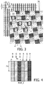
- Figure 3 shows the native pixel layout of the 2D display panel as well as, on the same scale, the pixel layout in a 3D view obtained by putting a lenticular in front of the panel.
- the pixel layout shown for the 3D image represents the pixel pattern as seen from one viewing direction.
- the same geometric pixel pattern is seen from all viewing directions, but different sets of sub-pixels of the underlying 2D display are visible.
- a blue 3D sub-pixel is an image of a one or more sub-pixels of the native 2D display (and the same applies for green and red).
- the lens pitch is thus 7.5 when expressed as a number of sub-pixel dimensions in the row direction.
- the 3D image has a repeating pattern of sub-pixels, and the colours of a few sub-pixels (R, G and B) are shown so that all colours in the pattern can be understood. Each colour is output as a diamond shaped grid of sub-pixels which are interleaved with each other.
- the slant angle of the lenticular as well as its pitch should be chosen such that a number of requirements are fulfilled as much as possible:
- the combination of a lenticular in front of a display panel is very susceptible to the occurrence of moire ('banding'). This effect is caused by the combination of the periodicity of the pixel layout of the display panel and the periodicity of the lenticular. It is worsened by the fact that the sub-pixels of the display panel are surrounded by a black matrix. By means of slanting the lenticular and by choosing the lenticular to have a width that is not equal to an integer times the width of a sub-pixel, this moire effect can be minimised.
- Figures 4 and 5 show two pixel layouts.
- the subpixels are identified with letter labels ("R", "G", "B” etc.) to denote the colour.
- the pixels are in repeating patterns. Where columns of pixels have the same colour, these are identified from above the columns. The colours of only enough pixels have been shown for the repeating pattern to be identified.
- FIG 4 shows a conventional RGB striped pixel layout. Each pixel has three sub-pixels, hence the subscript "3" in RGB_3 (the same notation is used for all pixel layouts).
- Multi-primary pixel layouts Pixel layouts using more than 3 primary colours are termed "multi-primary" pixel layouts. Several such multi-primary layouts have reached the market and are expected to become mainstream.
- this layout results in a larger colour gamut.
- the parameters can be altered slightly to provide a so-called fractional design to reduce banding, in particular with a pitch a/b with a and b being integers and b>2.
- fractional views are discussed in O.H. Willemsen, S.T. de Zwart and W.L. IJzerman, "Fractional viewing systems to reduce banding in lenticular based 3D displays", Proc. Int. Disp. Workshops, vol. 12, pp. 1789-1792, 2005 .
- Figure 6 shows the native 2D panel with RGB stripes and the lens positions for 4 2/3 sub-pixels and slant 1/6.
- the number of fractional views is 28 in that there are 28 possible positions of a subpixel with respect to the lens, but counting only views with little or no crosstalk in between, then 4 views is a realistic number.
- Figure 7 shows the native 2D panel with RGB stripes and the lens positions for 4 1/2 sub-pixels.
- the pitch number p in sub-pixel units indicates the number of separable views (i.e. 4 or more) and the spatial resolution of a view is 1/p times of the native resolution.
- the lenticular lens By placing the lenticular lens on top of a display panel, multiple angular views can be generated. The exact shape of the sub-pixels pixels in these views depends on the parameters of the lenticular lens and the slant under which the lens is placed with respect to the underlying display panel.
- Figure 8 shows 3D sub-pixels created by placing a lenticular lens with pitch p under slant s onto a display panel. As shown in Figure 9 , the 3D sub-pixels have width w and height h.
- the important parameters in defining these 3D sub-pixel shapes are the pitch p of the lenticular lenses and the slant s .
- the sub-pixels are in general positioned differently than in the underlying display panel. There is the freedom how to define 3D pixels from neighboring 3D sub-pixels.
- This invention provides a design space for lenticular lenses, such that the 3D pixels are square or near square and that the sacrifice in panel resolution is evenly distributed in the horizontal direction and the vertical direction, leading to a conservation of the aspect ratio in the pixels of the generated views.
- the height should be ⁇ times its width.
- the ⁇ indicates that the slant can be in either sense (clockwise or counter clockwise about the column direction).
- the resulting 3D pixel with a unity aspect ratio is shown in Figure 11 .
- the invention provides a way to choose the slant based on the required reduction in spatial resolution in the 3D views.
- ⁇ satisfies 0.8 ⁇ ⁇ ⁇ 1 0.8 .
- the 3D pixel components are formed by more than one 2D pixel components. In the example shown, two components of each primary are involved.
- Quad Full HD RGB panel HD 3D resolution Native resolution Width 3840 px Height 2160 px Colors, c 3 3D resolution Width 1280 px Height 720 px Colors, c 3 Area, A 9 2D px Design suggestion Slant, s 0.354 Pitch, p 3.182 px 9.546 subpx Super Hi-Vision RGB panel, Full HD 3d resolution Native resolution Width 7680 px Height 4320 px Colors, c 3 3D resolution Width 1920 px Height 1080 px Colors, c 3 Area, A 16 2D px Design suggestion Slant, s 0.258 Pitch, p 4.131 px 12.394 subpx Super Hi-Vision RGB panel, 110% Full HD 3D resolution Native resolution Width 7680 px Height 4320 px Colors, c 3 3 3
- the invention provides a lenticular autostereoscopic display device with a particular design of lenticular array (slant angle and pitch angle) to optimise the quality of the views provided to the user.
- the invention enables pitch and slant angles to be optimised to achieve square or near square 3D pixels.
- the invention in general comprises the following embodiments:
Landscapes
- Engineering & Computer Science (AREA)
- Physics & Mathematics (AREA)
- Multimedia (AREA)
- Signal Processing (AREA)
- General Physics & Mathematics (AREA)
- Optics & Photonics (AREA)
- Chemical & Material Sciences (AREA)
- Crystallography & Structural Chemistry (AREA)
- Computer Hardware Design (AREA)
- Theoretical Computer Science (AREA)
- Geometry (AREA)
- Testing, Inspecting, Measuring Of Stereoscopic Televisions And Televisions (AREA)
- Stereoscopic And Panoramic Photography (AREA)
Abstract
Description
- This invention relates to an autostereoscopic display device which comprises a display panel having an array of display pixels, and an arrangement for directing different views to different physical locations.
- A known autostereoscopic display device comprises a two dimensional emissive liquid crystal display panel having a row and column array of display pixels acting as an image forming means to produce a display. An array of elongate lenses extending parallel to one another overlies the display pixel array and acts as a view forming means. These are known as "lenticular lenses". Outputs from the display pixels are projected through these lenticular lenses, which function to modify the directions of the outputs.
- The lenticular lenses are provided as a sheet of lens elements, each of which comprises an elongate semi-cylindrical lens element. The lenticular lenses extend in the column direction of the display panel, with each lenticular lens overlying a respective group of two or more adjacent columns of display pixels.
- Each lenticular lens can be associated with two columns of display pixels to enable a user to observe a single stereoscopic image. Instead, each lenticular lens can be associated with a group of three or more adjacent display pixels in the row direction. Corresponding columns of display pixels in each group are arranged appropriately to provide a vertical slice from a respective two dimensional sub-image. As a user's head is moved from left to right a series of successive, different, stereoscopic views are observed creating, for example, a look-around impression.
- The above described autostereoscopic display device produces a display having good levels of brightness. However, one problem associated with the device is that the views projected by the lenticular sheet are separated by dark zones caused by "imaging" of the non-emitting black matrix which typically defines the display pixel array. These dark zones are readily observed by a user as brightness non-uniformities in the form of dark vertical bands spaced across the display. The bands move across the display as the user moves from left to right and the pitch of the bands changes as the user moves towards or away from the display. Another problem is that the vertical lens result in a much greater reduction in resolution in the horizontal direction than in the vertical direction.
- Both of these issues can be at least partly addressed by the well-known technique of slanting the lenticular lenses at an acute angle relative to the column direction of the display pixel array. The use of slanted angles lenses is thus recognised as an essential feature to produce different views with near constant brightness, and a good RGB distribution behind the lenses.
- Traditionally, display panels are based on a matrix of pixels that are square in shape. In order to generate images in colour, the pixels are divided into sub-pixels. Traditionally, each pixel is divided into 3 sub-pixels, transmitting or emitting red (R), green (G) and blue (B) light, respectively. Sub-pixels of equal colour are typically arranged in columns.
-
WO2010/070564 discloses an arrangement in which the lens pitch and lens slant are selected in such a way as to provide an improved pixel layout in the views created by the lenticular array, in terms of spacing of colour sub-pixels, and uniformity of colour density. This case relates to the arrangement of the grid of pixels forming the 3D image, rather than the individual pixels. - The invention concerns the shape of the individual pixels forming the 3D image.
-
WO 2010/070564 discloses an autostereoscopic display with slanted lenticular lenses wherein a particular lens pitch is selected to achieve a uniform and regular distribution of 3D pixels. - The invention is defined by the claims.
- According to a first aspect of the invention, there is provided an autostereoscopic display device comprising:
- a display having an array of display pixels for producing a display, wherein the display pixels are arranged in rows and columns of different colour sub-pixels;
- a lens array arranged in registration with the display for projecting a plurality of views towards a user in different directions, and comprising elongate lenses configurable to focus outputs of groups of the display pixels into the plurality of views projected towards a user in different directions, thereby enabling autostereoscopic imaging, wherein the elongate lenses have a long axis which is slanted at an angle θ to the general column pixel direction, wherein:

and wherein
- The invention provides a design space in which the 3D pixels can be designed to have an equal aspect ratio resolution as the underlying display panel. The design space offers good designs for high resolution panels such as Super Hi-Vision (SHV) displays. The 3D views will always have a lower spatial resolution than the underlying panel. The desired reduction factor in resolution, A, can be used to calculate the required pitch:

- Each pixel of the display can comprise a striped RGB pixel with red green and blue sub-pixels each extending in the column direction and arranged side by side. Alternatively, each pixel of the display comprises a striped RGBY pixel with red green blue and yellow sub-pixels each extending in the column direction and arranged side by side. Other pixel configurations can also be used.
- In one example c=3 and A=9. This is of particular interest for a Super Hi-Vision RGB panel of 7680 x 4320 RGB pixels, with
Quad HD 3D resolution of 2560 x 1440 3D RGB pixels. - In another example c=4 and A=16. This is of particular interest for a Super Hi-Vision RGBY panel of 7680 x 4320 RGBY pixels, with
Quad HD 3D resolution of 1920 x 1080 3D RGBY pixels. - In other arrangements, c=3 and A=16 or c=4 and A=9.
- The invention also provides a method of determining the slant angle for an elongate lens array of an autostereoscopic display device, wherein the device comprises a display having an array of display pixels for producing a display, wherein the display pixels are arranged in rows and columns of different colour sub-pixels and a lens array arranged in registration with the display for projecting a plurality of views towards a user in different directions, and comprising elongate lenses configurable to focus outputs of groups of the display pixels into the plurality of views projected towards a user in different directions, thereby enabling autostereoscopic imaging, wherein the elongate lenses have a long axis which is slanted at an angle θ to the general column pixel direction, wherein the method comprises setting:


- Embodiments of the invention will now be described, purely by way of example, with reference to the accompanying drawings, in which:
-
Figure 1 is a schematic perspective view of a known autostereoscopic display device; -
Figure 2 is a schematic cross sectional view of the display device shown inFigure 1 ; -
Figure 3 shows how the known RGB pixel is projected by the lenticular arrangement in a known display; -
Figure 4 shows the known RGB pixel layout and a known RGBW pixel for a display to which the invention can be applied; -
Figure 5 shows an RGBY pixel layout for a display to which the invention can be applied; -
Figure 6 shows a fractional arrangement with 4.66 subpixels per lenticular lens pitch; -
Figure 7 shows a fractional arrangement with 4.5 subpixels per lenticular lens pitch; -
Figure 8 shows lens pitch and slant parameters; -
Figure 9 shows how the lens pitch and slant parameters translate to dimensions of a sub-pixel of the 3D display output; -
Figure 10 shows the shape of a full 3D pixel; -
Figure 11 shows 3D display pixel arrangement to be achieved by the design of the invention; - The invention provides a lenticular autostereoscopic display device with a particular design of lenticular array (slant angle and preferably also lens pitch) to optimise the quality of the views provided to the user. In particular, the invention enables pitch and slant angles to be optimised to achieve 3D pixels with a similar aspect ratio as the underlying pixels. In practise this usually means that the invention leads to square or near square 3D pixels.
- Before describing the invention in detail, the configuration of a known autostereoscopic display will first be described.
-
Figure 1 is a schematic perspective view of a known multi-viewautostereoscopic display device 1. The knowndevice 1 comprises a liquidcrystal display panel 3 of the active matrix type that acts as an image forming means to produce the display. - The
display panel 3 has an orthogonal array ofdisplay pixels 5 arranged in rows and columns. For the sake of clarity, only a small number ofdisplay pixels 5 are shown inFigure 1 . In practice, thedisplay panel 3 might comprise about one thousand rows and several thousand columns ofdisplay pixels 5. - The structure of the liquid
crystal display panel 3 is entirely conventional. In particular, thepanel 3 comprises a pair of spaced transparent glass substrates, between which an aligned twisted nematic or other liquid crystal material is provided. The substrates carry patterns of transparent indium tin oxide (ITO) electrodes on their facing surfaces. Polarising layers are also provided on the outer surfaces of the substrates. - Each
display pixel 5 comprises opposing electrodes on the substrates, with the intervening liquid crystal material therebetween. The shape and layout of thedisplay pixels 5 are determined by the shape and layout of the electrodes and a black matrix arrangement provided on the front of thepanel 3. Thedisplay pixels 5 are regularly spaced from one another by gaps. - Each
display pixel 5 is associated with a switching element, such as a thin film transistor (TFT) or thin film diode (TFD). The display pixels are operated to produce the display by providing addressing signals to the switching elements, and suitable addressing schemes will be known to those skilled in the art. - The
display panel 3 is illuminated by alight source 7 comprising, in this case, a planar backlight extending over the area of the display pixel array. Light from thelight source 7 is directed through thedisplay panel 3, with theindividual display pixels 5 being driven to modulate the light and produce the display. - The
display device 1 also comprises alenticular sheet 9, arranged over the display side of thedisplay panel 3, which performs a view forming function. Thelenticular sheet 9 comprises a row oflenticular lenses 11 extending parallel to one another, of which only one is shown with exaggerated dimensions for the sake of clarity. Thelenticular lenses 11 act as view forming elements to perform a view forming function. - The
lenticular lenses 11 are in the form of convex cylindrical elements, and they act as a light output directing means to provide different images, or views, from thedisplay panel 3 to the eyes of a user positioned in front of thedisplay device 1. - The
autostereoscopic display device 1 shown inFigure 1 is capable of providing several different perspective views in different directions. In particular, eachlenticular lens 11 overlies a small group ofdisplay pixels 5 in each row. Thelenticular element 11 projects eachdisplay pixel 5 of a group in a different direction, so as to form the several different views. As the user's head moves from left to right, his/her eyes will receive different ones of the several views, in turn. -
Figure 2 shows the principle of operation of a lenticular type imaging arrangement as described above and shows thelight source 7,display panel 3 and thelenticular sheet 9. The arrangement provides three views each projected in different directions. Each pixel of thedisplay panel 3 is driven with information for one specific view. - The above described autostereoscopic display device produces a display having good levels of brightness. It is well known to slant the lenticular lenses at an acute angle relative to the column direction of the display pixel array. This enables an improved brightness uniformity and also brings the horizontal and vertical resolutions closer together.
- Whatever the mechanism used to obtain an auto-stereoscopic display system, resolution is traded for depth: the more views, the higher the loss in resolution per view. This is illustrated in
Figure 3 , which shows the native pixel layout of the 2D display panel as well as, on the same scale, the pixel layout in a 3D view obtained by putting a lenticular in front of the panel. - The pixel layout shown for the 3D image represents the pixel pattern as seen from one viewing direction. The same geometric pixel pattern is seen from all viewing directions, but different sets of sub-pixels of the underlying 2D display are visible. For a given viewing direction as shown, a blue 3D sub-pixel is an image of a one or more sub-pixels of the native 2D display (and the same applies for green and red).
- The lenticular has a slant s = tan(θ)=1/6 and a lens pitch PL=2.5 px (where px is the pixel pitch in the row direction) resulting in 15 views. In this case, px=py. The lens pitch is thus 7.5 when expressed as a number of sub-pixel dimensions in the row direction. The 3D image has a repeating pattern of sub-pixels, and the colours of a few sub-pixels (R, G and B) are shown so that all colours in the pattern can be understood. Each colour is output as a diamond shaped grid of sub-pixels which are interleaved with each other.
- The slant angle of the lenticular as well as its pitch should be chosen such that a number of requirements are fulfilled as much as possible:
- (i) A favourable distribution of pixels should be obtained for each 3D view.
In each of the 3D views the sub-pixels of each colour should be distributed in a pattern that is regular and having a resolution that is similar for the horizontal and vertical direction. As shown inFigure 3 , the horizontal distance between neighbouring green pixels (labelled A inFigure 3 ) should be comparable to the vertical distance between neighbouring green pixels (labelled B). This should hold for the other colours as well. - (ii) The surface area occupied by pixels of the same colours should be equal for each 3D view.
- (iii) Absence of moire.
- The combination of a lenticular in front of a display panel is very susceptible to the occurrence of moire ('banding'). This effect is caused by the combination of the periodicity of the pixel layout of the display panel and the periodicity of the lenticular. It is worsened by the fact that the sub-pixels of the display panel are surrounded by a black matrix. By means of slanting the lenticular and by choosing the lenticular to have a width that is not equal to an integer times the width of a sub-pixel, this moire effect can be minimised.
- Recently, display manufacturers started looking into alternative pixel layouts using more than 3 primary colours.
-
Figures 4 and5 show two pixel layouts. The subpixels are identified with letter labels ("R", "G", "B" etc.) to denote the colour. The pixels are in repeating patterns. Where columns of pixels have the same colour, these are identified from above the columns. The colours of only enough pixels have been shown for the repeating pattern to be identified. -
Figure 4 shows a conventional RGB striped pixel layout. Each pixel has three sub-pixels, hence the subscript "3" in RGB_3 (the same notation is used for all pixel layouts). - Pixel layouts using more than 3 primary colours are termed "multi-primary" pixel layouts. Several such multi-primary layouts have reached the market and are expected to become mainstream.
-
Figure 5 shows an RGBY (Y=Yellow) pixel layout, which has been used by Sharp. InFigure 5 , px R=px B=2 px G=2px Y (the red and blue sub-pixels are twice as wide as the green and yellow sub-pixels in the row direction). Compared to the RGB layouts, this layout results in a larger colour gamut. - As explained above, for autostereoscopic displays, spatial resolution is usually sacrificed to create angular resolution in the form of views. Current best lens designs offer an unequal trade-off between horizontal and vertical spatial resolution, resulting in 3D views with pixels that have a different aspect ratio than that of the original pixels of the underlying panel. This usually means that the horizontal 3D pixel density is inconveniently different from the vertical 3D pixel density.
- An optimal lens design must take account of the underlying display pixel layout. The most common current display resolutions are defined in the table below:
Name Abbreviation Horizontal Vertical Color Elements High definition HD 1280 720 RGB 2.7 MP Full high definition FHD 1920 1080 RGB 6.2 MP Quad high definition QHD 2560 1440 RGB 11 MP Quad full high definition QFHD 3840 2160 RGB 25 MP Super Hi-Vision SHV 7680 4320 RGB 100 MP - For Full HD and Quad Full HD displays, suitable design parameters for an autostereoscopic lens design have been proposed with pitch around 4½ sub-pixels and
slant 1/6. - The parameters can be altered slightly to provide a so-called fractional design to reduce banding, in particular with a pitch a/b with a and b being integers and b>2. The use of fractional views is discussed in O.H. Willemsen, S.T. de Zwart and W.L. IJzerman, "Fractional viewing systems to reduce banding in lenticular based 3D displays", Proc. Int. Disp. Workshops, vol. 12, pp. 1789-1792, 2005.
-
Figure 6 shows the native 2D panel with RGB stripes and the lens positions for 4 2/3 sub-pixels andslant 1/6. The number of fractional views is 28 in that there are 28 possible positions of a subpixel with respect to the lens, but counting only views with little or no crosstalk in between, then 4 views is a realistic number. -
Figure 7 shows the native 2D panel with RGB stripes and the lens positions for 4 1/2 sub-pixels. - It is difficult to estimate the spatial and angular resolution of a lenticular display as each pixel component adds both to angular and spatial resolution. As a rule of thumb, the pitch number p in sub-pixel units indicates the number of separable views (i.e. 4 or more) and the spatial resolution of a view is 1/p times of the native resolution.
- By placing the lenticular lens on top of a display panel, multiple angular views can be generated. The exact shape of the sub-pixels pixels in these views depends on the parameters of the lenticular lens and the slant under which the lens is placed with respect to the underlying display panel.
-
Figure 8 shows 3D sub-pixels created by placing a lenticular lens with pitch p under slant s onto a display panel. As shown inFigure 9 , the 3D sub-pixels have width w and height h. - The important parameters in defining these 3D sub-pixel shapes are the pitch p of the lenticular lenses and the slant s. The height h of a 3D sub-pixel can be derived from
Figure 9 and is given by

- In a 3D view the sub-pixels are in general positioned differently than in the underlying display panel. There is the freedom how to define 3D pixels from neighboring 3D sub-pixels.
- This invention provides a design space for lenticular lenses, such that the 3D pixels are square or near square and that the sacrifice in panel resolution is evenly distributed in the horizontal direction and the vertical direction, leading to a conservation of the aspect ratio in the pixels of the generated views.
- To achieve this aim:
- 1. The 3D pixel is composed of c sub-pixels that are positioned below each other along the direction of the lenticulars.
Figure 10 shows the basic pixel layout. The parameter c is the number of sub-pixels that constitute the original pixels of the display. - 2. The slant and pitch are adjusted in such a way that the full 3D pixel is sufficiently square. A method to find the correct slant and pitch is given below.
- In this way, the 3D pixel is composed of
c 3D sub-pixels, which are oriented along the direction of the lenticular lenses. Therefore the height H and the width W of the complete 3D pixel, as shown inFigure 11 , are given by:

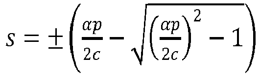
- If it is imposed that the pixels should have an aspect ratio α, the height should be α times its width. Using Eq. 3 and Eq. 4 and solving for s an expression for the slant s in terms of the pitch p and the pixel aspect ratio α is:



Figure 11 . - In this way, for a given slant and 3D pixel aspect ratio, the pitch is set. However, there is still freedom to select the slant.
- The invention provides a way to choose the slant based on the required reduction in spatial resolution in the 3D views.
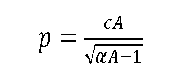
- In the layout of the invention, the 3D pixels have an aspect ratio of α and the 3D pixels are rotated by the slant s. If the area of a 3D pixel is A (in units of the full 2D pixel area), the reduction in resolution is also A. With this knowledge, a reduction in resolution of a factor A can be created by choosing the proper slant:

- It should be understood that in practice the 3D pixel does not have to be exactly square (α = 1), but sufficiently close to square.
- Thus, preferably, α satisfies

- For example for a given slant, Eq. 5 could give a pitch that leads to a discomforting 3D pixel layout if α = 1 is used. It would then be appropriate to slightly adjust α in Eq. 5 to optimize the 3D pixel layout without disturbing the original layout too much.
- From
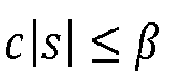
Figure 11 it can be observed that the 3D pixel components are formed by more than one 2D pixel components. In the example shown, two components of each primary are involved. - This happens for all slants |s| < 1/c with c the number of components per pixel. For slants |s| ≥ 1/c this does not happen (so that one 2D sub-pixel maps to one 3D sub-pixel), but the bigger the slant, the wider the angular crosstalk profile.
- With this motivation, in a preferred embodiment, the slant is within



- The underlining principles have been outlined above. Below are some specific examples. For simplicity, the aspect ratio α = 1 has been used for all these examples.
Quad Full HD RGB panel, HD 3D resolution Native resolution Width 3840 px Height 2160 px Colors, c 3 3D resolution Width 1280 px Height 720 px Colors, c 3 Area, A 9 2D px Design suggestion Slant, s 0.354 Pitch, p 3.182 px 9.546 subpx Super Hi-Vision RGB panel, Full HD 3d resolution Native resolution Width 7680 px Height 4320 px Colors, c 3 3D resolution Width 1920 px Height 1080 px Colors, c 3 Area, A 16 2D px Design suggestion Slant, s 0.258 Pitch, p 4.131 px 12.394 subpx Super Hi-Vision RGB panel, 110% Full HD 3D resolution Native resolution Width 7680 px Height 4320 px Colors, c 3 3D resolution Width 2110 px Height 1187 px Colors, c 3 Area, A 13.25 2D px Design suggestion Slant, s 0.286 Pitch, p 3.785 px 11.356 subpx Super Hi-Vision RGB panel, Quad HD 3D resolution Native resolution Width 7680 px Height 4320 px Colors, c 3 3D resolution Width 2560 px Height 1440 px Colors, c 3 Area, A 9 2D px Design suggestion Slant, s 0.354 Pitch, p 3.182 px 9.546 subpx Super Hi-Vision RGBY panel, Full HD 3D resolution Native resolution Width 7680 px Height 4320 px Colors, c 4 3D resolution Width 1920 px Height 1080 px Colors, c 4 Area, A 16 Design suggestion Slant, s 0.258 Pitch, p 4.131 px 16.525 subpx - Shortly summarized the invention provides a lenticular autostereoscopic display device with a particular design of lenticular array (slant angle and pitch angle) to optimise the quality of the views provided to the user. In particular, the invention enables pitch and slant angles to be optimised to achieve square or near square 3D pixels.
The invention in general comprises the following embodiments: -
- 1. An autostereoscopic display device comprising:
- a display (3) having an array of display pixels (5) for producing a display, wherein the display pixels are arranged in rows and columns of different colour sub-pixels;
- a lens array (9) arranged in registration with the display for projecting a plurality of views towards a user in different directions, and comprising elongate lenses configurable to focus outputs of groups of the display pixels into the plurality of views projected towards a user in different directions, thereby enabling autostereoscopic imaging, wherein the elongate lenses have a long axis which is slanted at an angle θ to the general column pixel direction,

characterised in that:
- 2. A device according to
embodiment 1, wherein each pixel (5) of the display comprises an RGB pixel with red green and blue sub-pixels each extending in the column direction and arranged side by side. - 3. A device according to
embodiments 1 or 2, wherein each pixel (5) of the display comprises an RGBY pixel with red green blue and yellow sub-pixels each extending in the column direction and arranged side by side. - 4. A device according to
embodiment 1, wherein c=3 and A=9. - 5. A device according to embodiment 4, wherein the display has a resolution of 7680 x 4320 RGB pixels.
- 6. A device according to
embodiment 1, wherein c=4 and A=16. - 7. A device according to embodiment 6, wherein the display has a resolution of 7680 x 4320 RGBY pixels.
- 8. A device according to
embodiment 1, wherein:- c=3 and A=16; or
- c=4 and A=9.
- 9. A display device according to any preceding embodiment, wherein the columns of pixels are parallel to a side edge of the display.
- 10. A method of determining the slant angle for a elongate lens array (9) of an autostereoscopic display device, wherein the device comprises a display (3) having an array of display pixels (5) for producing a display, wherein the display pixels (5) are arranged in rows and columns of different colour sub-pixels and a lens array arranged in registration with the display for projecting a plurality of views towards a user in different directions, and comprising elongate lenses configurable to focus outputs of groups of the display pixels into the plurality of views projected towards a user in different directions, thereby enabling autostereoscopic imaging, wherein the elongate lenses have a long axis which is slanted at an angle θ to the general column pixel direction,
wherein the method comprises setting:
characterised in that the method comprises setting:

- More particularly the invention comprises the embodiments as claimed in the appended claims.
- It should be noted that the above-mentioned disclosed and/or claimed embodiments illustrate rather than limit the invention, and that those skilled in the art will be capable of designing many alternative embodiments without departing from the scope of the invention as defined by the appended claims.
- Other variations to the disclosed and/or claimed embodiments can be understood and effected by those skilled in the art in practicing the claimed invention, from a study of the drawings, the disclosure, and the appended claims. In the claims, the word "comprising" does not exclude other elements or steps, and the indefinite article "a" or "an" does not exclude a plurality. The mere fact that certain measures are recited in mutually different dependent claims does not indicate that a combination of these measured cannot be used to advantage. Any reference signs in the claims should not be construed as limiting the scope.
Claims (10)
- An autostereoscopic display device comprising:a display panel (3) having an array of pixels (5) for producing a display, wherein the pixels are arranged in rows and columns of different colour sub-pixels;a lens array (9) arranged in registration with the display panel for projecting a plurality of views towards a user in different directions, and comprising elongate lenses configurable to focus outputs of groups of the pixels into the plurality of views projected towards a user in different directions, thereby enabling autostereoscopic imaging, wherein the elongate lenses have a long axis which is slanted at an angle θ to the general column pixel direction,characterized in that:

characterised in that:

- A device as claimed in claim 1, wherein each pixel (5) comprises an RGB pixel with red green and blue sub-pixels each extending in the column direction and arranged side by side.
- A device as claimed in claim 1 or 2, wherein each pixel (5) comprises an RGBY pixel with red green blue and yellow sub-pixels each extending in the column direction and arranged side by side.
- A device as claimed in claim 1, wherein c=3 and A=9.
- A device as claimed in claim 4, wherein the display has a resolution of 7680 x 4320 RGB pixels.
- A device as claimed in claim 1, wherein c=4 and A=16.
- A device as claimed in claim 6, wherein the display has a resolution of 7680 x 4320 RGBY pixels.
- A device as claimed in claim 1, wherein:c=3 and A=16; orc=4 and A=9.
- A display device as claimed in any preceding claim, wherein the columns of pixels are parallel to a side edge of the display.
- A method of determining the slant angle for an elongate lens array (9) of an autostereoscopic display device, wherein the device comprises a display panel (3) having an array of pixels (5) for producing a display, wherein the pixels (5) are arranged in rows and columns of different colour sub-pixels and a lens array arranged in registration with the display panel for projecting a plurality of views towards a user in different directions, and comprising elongate lenses configurable to focus outputs of groups of the pixels into the plurality of views projected towards a user in different directions, thereby enabling autostereoscopic imaging, wherein the elongate lenses have a long axis which is slanted at an angle θ to the general column pixel direction,
wherein the method comprises setting:
by setting:

Priority Applications (2)
| Application Number | Priority Date | Filing Date | Title |
|---|---|---|---|
| EP20185978.2A EP3757661A1 (en) | 2013-03-22 | 2014-03-19 | Autostereoscopic display device |
| PL16183300T PL3121640T3 (en) | 2013-03-22 | 2014-03-19 | Autostereoscopic display device |
Applications Claiming Priority (3)
| Application Number | Priority Date | Filing Date | Title |
|---|---|---|---|
| EP13160530 | 2013-03-22 | ||
| EP14710901.1A EP2976673B1 (en) | 2013-03-22 | 2014-03-19 | Autostereoscopic display device |
| PCT/EP2014/055461 WO2014147100A1 (en) | 2013-03-22 | 2014-03-19 | Autostereoscopic display device |
Related Parent Applications (2)
| Application Number | Title | Priority Date | Filing Date |
|---|---|---|---|
| EP14710901.1A Division EP2976673B1 (en) | 2013-03-22 | 2014-03-19 | Autostereoscopic display device |
| EP14710901.1A Division-Into EP2976673B1 (en) | 2013-03-22 | 2014-03-19 | Autostereoscopic display device |
Related Child Applications (2)
| Application Number | Title | Priority Date | Filing Date |
|---|---|---|---|
| EP20185978.2A Division EP3757661A1 (en) | 2013-03-22 | 2014-03-19 | Autostereoscopic display device |
| EP20185978.2A Division-Into EP3757661A1 (en) | 2013-03-22 | 2014-03-19 | Autostereoscopic display device |
Publications (2)
| Publication Number | Publication Date |
|---|---|
| EP3121640A1 true EP3121640A1 (en) | 2017-01-25 |
| EP3121640B1 EP3121640B1 (en) | 2020-11-04 |
Family
ID=47913205
Family Applications (3)
| Application Number | Title | Priority Date | Filing Date |
|---|---|---|---|
| EP14710901.1A Active EP2976673B1 (en) | 2013-03-22 | 2014-03-19 | Autostereoscopic display device |
| EP20185978.2A Withdrawn EP3757661A1 (en) | 2013-03-22 | 2014-03-19 | Autostereoscopic display device |
| EP16183300.9A Active EP3121640B1 (en) | 2013-03-22 | 2014-03-19 | Autostereoscopic display device |
Family Applications Before (2)
| Application Number | Title | Priority Date | Filing Date |
|---|---|---|---|
| EP14710901.1A Active EP2976673B1 (en) | 2013-03-22 | 2014-03-19 | Autostereoscopic display device |
| EP20185978.2A Withdrawn EP3757661A1 (en) | 2013-03-22 | 2014-03-19 | Autostereoscopic display device |
Country Status (15)
| Country | Link |
|---|---|
| US (2) | US9451243B2 (en) |
| EP (3) | EP2976673B1 (en) |
| JP (1) | JP5899389B1 (en) |
| KR (1) | KR101648210B1 (en) |
| CN (1) | CN105051591B (en) |
| BR (1) | BR112015023957B1 (en) |
| CA (1) | CA2902834C (en) |
| ES (2) | ES2604984T3 (en) |
| MX (1) | MX345220B (en) |
| PH (1) | PH12015501917A1 (en) |
| PL (2) | PL2976673T3 (en) |
| RU (1) | RU2655624C2 (en) |
| TW (1) | TWI601980B (en) |
| WO (1) | WO2014147100A1 (en) |
| ZA (1) | ZA201507838B (en) |
Families Citing this family (19)
| Publication number | Priority date | Publication date | Assignee | Title |
|---|---|---|---|---|
| KR102141520B1 (en) * | 2014-02-21 | 2020-08-05 | 삼성전자주식회사 | Autostereoscopic multi-view image display apparatus |
| RU2695941C2 (en) * | 2014-12-24 | 2019-07-29 | Конинклейке Филипс Н.В. | Autostereoscopic display device and excitation method |
| BR112017013572B1 (en) * | 2014-12-24 | 2021-03-02 | Koninklijke Philips N.V | self-stereoscopic screen, and portable device |
| CN105116558A (en) * | 2015-09-10 | 2015-12-02 | 深圳市华星光电技术有限公司 | 3d display device |
| US10375379B2 (en) * | 2015-09-17 | 2019-08-06 | Innolux Corporation | 3D display device |
| RU2720660C2 (en) * | 2015-11-10 | 2020-05-12 | Конинклейке Филипс Н.В. | Display device and a display device control method |
| JP2017181787A (en) * | 2016-03-30 | 2017-10-05 | ソニー株式会社 | Display device, optical element, and electronic device |
| KR102602248B1 (en) * | 2016-10-28 | 2023-11-15 | 삼성디스플레이 주식회사 | Light fiield display apparatus |
| CN109389911B (en) * | 2017-08-03 | 2020-12-04 | 广东烨嘉光电科技股份有限公司 | A design method of light field display screen |
| CN114815287B (en) | 2017-08-23 | 2024-08-13 | 交互数字麦迪逊专利控股公司 | Light field image engine method and apparatus for generating projected 3D light fields |
| CN111295612B (en) | 2017-11-02 | 2023-03-03 | Pcms控股公司 | Method and system for aperture expansion in light field displays |
| DE102019100066A1 (en) * | 2019-01-03 | 2020-07-09 | Psholix Ag | Auto stereoscopic display with integral imaging like optical elements |
| CN109785414A (en) * | 2019-01-24 | 2019-05-21 | 广东交通职业技术学院 | A kind of simulation animation production method generated for demonstrating object's three-view |
| EP3980820B1 (en) | 2019-06-07 | 2024-07-31 | InterDigital Madison Patent Holdings, SAS | Optical method and system for light field displays based on distributed apertures |
| EP3990972A1 (en) | 2019-06-28 | 2022-05-04 | PCMS Holdings, Inc. | Optical method and system for light field (lf) displays based on tunable liquid crystal (lc) diffusers |
| KR20210074814A (en) * | 2019-12-12 | 2021-06-22 | 쓰리디아이즈 주식회사 | Display device |
| JP7516781B2 (en) * | 2020-03-04 | 2024-07-17 | 富士フイルムビジネスイノベーション株式会社 | Display system, display control device and program |
| RU2751063C1 (en) * | 2020-11-26 | 2021-07-07 | Федеральное государственное автономное образовательное учреждение высшего образования "Сибирский федеральный университет" | Alloy based on 585-grade platinum |
| JP2021060617A (en) * | 2020-12-29 | 2021-04-15 | ソニー株式会社 | Display device and electronic apparatus |
Citations (2)
| Publication number | Priority date | Publication date | Assignee | Title |
|---|---|---|---|---|
| WO2006117707A2 (en) * | 2005-04-29 | 2006-11-09 | Koninklijke Philips Electronics N.V. | A stereoscopic display apparatus |
| WO2010070564A1 (en) | 2008-12-18 | 2010-06-24 | Koninklijke Philips Electronics N.V. | Autostereoscopic display device |
Family Cites Families (10)
| Publication number | Priority date | Publication date | Assignee | Title |
|---|---|---|---|---|
| GB9623682D0 (en) * | 1996-11-14 | 1997-01-08 | Philips Electronics Nv | Autostereoscopic display apparatus |
| JP2007140554A (en) * | 2004-02-10 | 2007-06-07 | Toshiba Corp | 3D image display device |
| KR101572791B1 (en) * | 2008-02-11 | 2015-12-01 | 코닌클리케 필립스 엔.브이. | Autostereoscopic image output device |
| KR20110096086A (en) * | 2008-12-22 | 2011-08-26 | 코닌클리케 필립스 일렉트로닉스 엔.브이. | Autostereoscopic Display Devices |
| JP5521380B2 (en) * | 2009-04-13 | 2014-06-11 | ソニー株式会社 | 3D display device |
| CN102004324B (en) * | 2010-10-19 | 2011-10-05 | 深圳超多维光电子有限公司 | Grating, three-dimensional display device and three-dimensional display method |
| KR101813614B1 (en) * | 2011-03-31 | 2018-01-02 | 삼성디스플레이 주식회사 | Lenticular unit for 2 dimension/3 dimension autostereoscopic display |
| JP5720421B2 (en) * | 2011-05-27 | 2015-05-20 | 株式会社Jvcケンウッド | Autostereoscopic display device |
| JP2013045087A (en) * | 2011-08-26 | 2013-03-04 | Toshiba Corp | Three-dimensional image display apparatus |
| JP5772688B2 (en) * | 2012-04-04 | 2015-09-02 | 株式会社Jvcケンウッド | Autostereoscopic display device |
-
2014
- 2014-03-19 JP JP2015560726A patent/JP5899389B1/en active Active
- 2014-03-19 EP EP14710901.1A patent/EP2976673B1/en active Active
- 2014-03-19 WO PCT/EP2014/055461 patent/WO2014147100A1/en not_active Ceased
- 2014-03-19 PL PL14710901T patent/PL2976673T3/en unknown
- 2014-03-19 MX MX2015011915A patent/MX345220B/en active IP Right Grant
- 2014-03-19 ES ES14710901.1T patent/ES2604984T3/en active Active
- 2014-03-19 BR BR112015023957-9A patent/BR112015023957B1/en not_active IP Right Cessation
- 2014-03-19 PL PL16183300T patent/PL3121640T3/en unknown
- 2014-03-19 US US14/772,220 patent/US9451243B2/en active Active
- 2014-03-19 EP EP20185978.2A patent/EP3757661A1/en not_active Withdrawn
- 2014-03-19 CN CN201480017460.3A patent/CN105051591B/en active Active
- 2014-03-19 RU RU2015145192A patent/RU2655624C2/en active
- 2014-03-19 CA CA2902834A patent/CA2902834C/en active Active
- 2014-03-19 KR KR1020157024719A patent/KR101648210B1/en active Active
- 2014-03-19 ES ES16183300T patent/ES2840024T3/en active Active
- 2014-03-19 EP EP16183300.9A patent/EP3121640B1/en active Active
- 2014-03-21 TW TW103110758A patent/TWI601980B/en active
-
2015
- 2015-09-01 PH PH12015501917A patent/PH12015501917A1/en unknown
- 2015-10-21 ZA ZA2015/07838A patent/ZA201507838B/en unknown
-
2016
- 2016-09-02 US US15/255,209 patent/US10212413B2/en active Active
Patent Citations (2)
| Publication number | Priority date | Publication date | Assignee | Title |
|---|---|---|---|---|
| WO2006117707A2 (en) * | 2005-04-29 | 2006-11-09 | Koninklijke Philips Electronics N.V. | A stereoscopic display apparatus |
| WO2010070564A1 (en) | 2008-12-18 | 2010-06-24 | Koninklijke Philips Electronics N.V. | Autostereoscopic display device |
Non-Patent Citations (1)
| Title |
|---|
| O.H. WILLEMSEN; S.T. DE ZWART; W.L. IJZERMAN: "Fractional viewing systems to reduce banding in lenticular based 3D displays", PROC. INT. DISP. WORKSHOPS, vol. 12, 2005, pages 1789 - 1792, XP007014840 |
Also Published As
Similar Documents
| Publication | Publication Date | Title |
|---|---|---|
| EP2976673B1 (en) | Autostereoscopic display device | |
| US8817082B2 (en) | Autostereoscopic display device | |
| US9250446B2 (en) | Autostereoscopic display device | |
| US20160234487A1 (en) | Autostereoscopic display device | |
| KR20100131449A (en) | Auto Stereoscopic Image Output Device | |
| WO2014173853A1 (en) | Auto-stereoscopic display device with a lenticular sheet slanted with respect to the column of colour sub-pixels |
Legal Events
| Date | Code | Title | Description |
|---|---|---|---|
| PUAI | Public reference made under article 153(3) epc to a published international application that has entered the european phase |
Free format text: ORIGINAL CODE: 0009012 |
|
| STAA | Information on the status of an ep patent application or granted ep patent |
Free format text: STATUS: THE APPLICATION HAS BEEN PUBLISHED |
|
| AC | Divisional application: reference to earlier application |
Ref document number: 2976673 Country of ref document: EP Kind code of ref document: P |
|
| AK | Designated contracting states |
Kind code of ref document: A1 Designated state(s): AL AT BE BG CH CY CZ DE DK EE ES FI FR GB GR HR HU IE IS IT LI LT LU LV MC MK MT NL NO PL PT RO RS SE SI SK SM TR |
|
| STAA | Information on the status of an ep patent application or granted ep patent |
Free format text: STATUS: REQUEST FOR EXAMINATION WAS MADE |
|
| 17P | Request for examination filed |
Effective date: 20170725 |
|
| RBV | Designated contracting states (corrected) |
Designated state(s): AL AT BE BG CH CY CZ DE DK EE ES FI FR GB GR HR HU IE IS IT LI LT LU LV MC MK MT NL NO PL PT RO RS SE SI SK SM TR |
|
| RAP1 | Party data changed (applicant data changed or rights of an application transferred) |
Owner name: KONINKLIJKE PHILIPS N.V. |
|
| REG | Reference to a national code |
Ref country code: DE Ref legal event code: R079 Ref document number: 602014072167 Country of ref document: DE Free format text: PREVIOUS MAIN CLASS: G02B0027220000 Ipc: G09G0003360000 |
|
| RIC1 | Information provided on ipc code assigned before grant |
Ipc: H04N 13/324 20180101ALI20200416BHEP Ipc: G09G 3/36 20060101AFI20200416BHEP Ipc: H04N 13/398 20180101ALI20200416BHEP Ipc: H04N 13/317 20180101ALI20200416BHEP Ipc: G02B 30/26 20200101ALI20200416BHEP Ipc: H04N 13/351 20180101ALI20200416BHEP Ipc: H04N 13/305 20180101ALI20200416BHEP |
|
| GRAP | Despatch of communication of intention to grant a patent |
Free format text: ORIGINAL CODE: EPIDOSNIGR1 |
|
| STAA | Information on the status of an ep patent application or granted ep patent |
Free format text: STATUS: GRANT OF PATENT IS INTENDED |
|
| INTG | Intention to grant announced |
Effective date: 20200528 |
|
| GRAS | Grant fee paid |
Free format text: ORIGINAL CODE: EPIDOSNIGR3 |
|
| GRAA | (expected) grant |
Free format text: ORIGINAL CODE: 0009210 |
|
| STAA | Information on the status of an ep patent application or granted ep patent |
Free format text: STATUS: THE PATENT HAS BEEN GRANTED |
|
| AC | Divisional application: reference to earlier application |
Ref document number: 2976673 Country of ref document: EP Kind code of ref document: P |
|
| AK | Designated contracting states |
Kind code of ref document: B1 Designated state(s): AL AT BE BG CH CY CZ DE DK EE ES FI FR GB GR HR HU IE IS IT LI LT LU LV MC MK MT NL NO PL PT RO RS SE SI SK SM TR |
|
| REG | Reference to a national code |
Ref country code: GB Ref legal event code: FG4D |
|
| REG | Reference to a national code |
Ref country code: CH Ref legal event code: EP |
|
| REG | Reference to a national code |
Ref country code: AT Ref legal event code: REF Ref document number: 1331836 Country of ref document: AT Kind code of ref document: T Effective date: 20201115 |
|
| REG | Reference to a national code |
Ref country code: DE Ref legal event code: R096 Ref document number: 602014072167 Country of ref document: DE |
|
| REG | Reference to a national code |
Ref country code: IE Ref legal event code: FG4D |
|
| REG | Reference to a national code |
Ref country code: NL Ref legal event code: MP Effective date: 20201104 |
|
| REG | Reference to a national code |
Ref country code: AT Ref legal event code: MK05 Ref document number: 1331836 Country of ref document: AT Kind code of ref document: T Effective date: 20201104 |
|
| PG25 | Lapsed in a contracting state [announced via postgrant information from national office to epo] |
Ref country code: GR Free format text: LAPSE BECAUSE OF FAILURE TO SUBMIT A TRANSLATION OF THE DESCRIPTION OR TO PAY THE FEE WITHIN THE PRESCRIBED TIME-LIMIT Effective date: 20210205 Ref country code: FI Free format text: LAPSE BECAUSE OF FAILURE TO SUBMIT A TRANSLATION OF THE DESCRIPTION OR TO PAY THE FEE WITHIN THE PRESCRIBED TIME-LIMIT Effective date: 20201104 Ref country code: PT Free format text: LAPSE BECAUSE OF FAILURE TO SUBMIT A TRANSLATION OF THE DESCRIPTION OR TO PAY THE FEE WITHIN THE PRESCRIBED TIME-LIMIT Effective date: 20210304 Ref country code: RS Free format text: LAPSE BECAUSE OF FAILURE TO SUBMIT A TRANSLATION OF THE DESCRIPTION OR TO PAY THE FEE WITHIN THE PRESCRIBED TIME-LIMIT Effective date: 20201104 Ref country code: NO Free format text: LAPSE BECAUSE OF FAILURE TO SUBMIT A TRANSLATION OF THE DESCRIPTION OR TO PAY THE FEE WITHIN THE PRESCRIBED TIME-LIMIT Effective date: 20210204 |
|
| PG25 | Lapsed in a contracting state [announced via postgrant information from national office to epo] |
Ref country code: AT Free format text: LAPSE BECAUSE OF FAILURE TO SUBMIT A TRANSLATION OF THE DESCRIPTION OR TO PAY THE FEE WITHIN THE PRESCRIBED TIME-LIMIT Effective date: 20201104 Ref country code: BG Free format text: LAPSE BECAUSE OF FAILURE TO SUBMIT A TRANSLATION OF THE DESCRIPTION OR TO PAY THE FEE WITHIN THE PRESCRIBED TIME-LIMIT Effective date: 20210204 Ref country code: SE Free format text: LAPSE BECAUSE OF FAILURE TO SUBMIT A TRANSLATION OF THE DESCRIPTION OR TO PAY THE FEE WITHIN THE PRESCRIBED TIME-LIMIT Effective date: 20201104 Ref country code: IS Free format text: LAPSE BECAUSE OF FAILURE TO SUBMIT A TRANSLATION OF THE DESCRIPTION OR TO PAY THE FEE WITHIN THE PRESCRIBED TIME-LIMIT Effective date: 20210304 Ref country code: LV Free format text: LAPSE BECAUSE OF FAILURE TO SUBMIT A TRANSLATION OF THE DESCRIPTION OR TO PAY THE FEE WITHIN THE PRESCRIBED TIME-LIMIT Effective date: 20201104 |
|
| REG | Reference to a national code |
Ref country code: LT Ref legal event code: MG9D |
|
| PG25 | Lapsed in a contracting state [announced via postgrant information from national office to epo] |
Ref country code: HR Free format text: LAPSE BECAUSE OF FAILURE TO SUBMIT A TRANSLATION OF THE DESCRIPTION OR TO PAY THE FEE WITHIN THE PRESCRIBED TIME-LIMIT Effective date: 20201104 |
|
| REG | Reference to a national code |
Ref country code: ES Ref legal event code: FG2A Ref document number: 2840024 Country of ref document: ES Kind code of ref document: T3 Effective date: 20210706 |
|
| PG25 | Lapsed in a contracting state [announced via postgrant information from national office to epo] |
Ref country code: SK Free format text: LAPSE BECAUSE OF FAILURE TO SUBMIT A TRANSLATION OF THE DESCRIPTION OR TO PAY THE FEE WITHIN THE PRESCRIBED TIME-LIMIT Effective date: 20201104 Ref country code: RO Free format text: LAPSE BECAUSE OF FAILURE TO SUBMIT A TRANSLATION OF THE DESCRIPTION OR TO PAY THE FEE WITHIN THE PRESCRIBED TIME-LIMIT Effective date: 20201104 Ref country code: LT Free format text: LAPSE BECAUSE OF FAILURE TO SUBMIT A TRANSLATION OF THE DESCRIPTION OR TO PAY THE FEE WITHIN THE PRESCRIBED TIME-LIMIT Effective date: 20201104 Ref country code: SM Free format text: LAPSE BECAUSE OF FAILURE TO SUBMIT A TRANSLATION OF THE DESCRIPTION OR TO PAY THE FEE WITHIN THE PRESCRIBED TIME-LIMIT Effective date: 20201104 Ref country code: CZ Free format text: LAPSE BECAUSE OF FAILURE TO SUBMIT A TRANSLATION OF THE DESCRIPTION OR TO PAY THE FEE WITHIN THE PRESCRIBED TIME-LIMIT Effective date: 20201104 Ref country code: EE Free format text: LAPSE BECAUSE OF FAILURE TO SUBMIT A TRANSLATION OF THE DESCRIPTION OR TO PAY THE FEE WITHIN THE PRESCRIBED TIME-LIMIT Effective date: 20201104 |
|
| REG | Reference to a national code |
Ref country code: DE Ref legal event code: R097 Ref document number: 602014072167 Country of ref document: DE |
|
| PG25 | Lapsed in a contracting state [announced via postgrant information from national office to epo] |
Ref country code: DK Free format text: LAPSE BECAUSE OF FAILURE TO SUBMIT A TRANSLATION OF THE DESCRIPTION OR TO PAY THE FEE WITHIN THE PRESCRIBED TIME-LIMIT Effective date: 20201104 |
|
| PLBE | No opposition filed within time limit |
Free format text: ORIGINAL CODE: 0009261 |
|
| STAA | Information on the status of an ep patent application or granted ep patent |
Free format text: STATUS: NO OPPOSITION FILED WITHIN TIME LIMIT |
|
| 26N | No opposition filed |
Effective date: 20210805 |
|
| PG25 | Lapsed in a contracting state [announced via postgrant information from national office to epo] |
Ref country code: NL Free format text: LAPSE BECAUSE OF FAILURE TO SUBMIT A TRANSLATION OF THE DESCRIPTION OR TO PAY THE FEE WITHIN THE PRESCRIBED TIME-LIMIT Effective date: 20201104 Ref country code: MC Free format text: LAPSE BECAUSE OF FAILURE TO SUBMIT A TRANSLATION OF THE DESCRIPTION OR TO PAY THE FEE WITHIN THE PRESCRIBED TIME-LIMIT Effective date: 20201104 Ref country code: AL Free format text: LAPSE BECAUSE OF FAILURE TO SUBMIT A TRANSLATION OF THE DESCRIPTION OR TO PAY THE FEE WITHIN THE PRESCRIBED TIME-LIMIT Effective date: 20201104 |
|
| REG | Reference to a national code |
Ref country code: CH Ref legal event code: PL |
|
| PG25 | Lapsed in a contracting state [announced via postgrant information from national office to epo] |
Ref country code: SI Free format text: LAPSE BECAUSE OF FAILURE TO SUBMIT A TRANSLATION OF THE DESCRIPTION OR TO PAY THE FEE WITHIN THE PRESCRIBED TIME-LIMIT Effective date: 20201104 |
|
| REG | Reference to a national code |
Ref country code: BE Ref legal event code: MM Effective date: 20210331 |
|
| PG25 | Lapsed in a contracting state [announced via postgrant information from national office to epo] |
Ref country code: LI Free format text: LAPSE BECAUSE OF NON-PAYMENT OF DUE FEES Effective date: 20210331 Ref country code: LU Free format text: LAPSE BECAUSE OF NON-PAYMENT OF DUE FEES Effective date: 20210319 Ref country code: CH Free format text: LAPSE BECAUSE OF NON-PAYMENT OF DUE FEES Effective date: 20210331 Ref country code: IE Free format text: LAPSE BECAUSE OF NON-PAYMENT OF DUE FEES Effective date: 20210319 |
|
| PG25 | Lapsed in a contracting state [announced via postgrant information from national office to epo] |
Ref country code: IS Free format text: LAPSE BECAUSE OF FAILURE TO SUBMIT A TRANSLATION OF THE DESCRIPTION OR TO PAY THE FEE WITHIN THE PRESCRIBED TIME-LIMIT Effective date: 20210304 |
|
| PG25 | Lapsed in a contracting state [announced via postgrant information from national office to epo] |
Ref country code: BE Free format text: LAPSE BECAUSE OF NON-PAYMENT OF DUE FEES Effective date: 20210331 |
|
| PG25 | Lapsed in a contracting state [announced via postgrant information from national office to epo] |
Ref country code: HU Free format text: LAPSE BECAUSE OF FAILURE TO SUBMIT A TRANSLATION OF THE DESCRIPTION OR TO PAY THE FEE WITHIN THE PRESCRIBED TIME-LIMIT; INVALID AB INITIO Effective date: 20140319 |
|
| PG25 | Lapsed in a contracting state [announced via postgrant information from national office to epo] |
Ref country code: CY Free format text: LAPSE BECAUSE OF FAILURE TO SUBMIT A TRANSLATION OF THE DESCRIPTION OR TO PAY THE FEE WITHIN THE PRESCRIBED TIME-LIMIT Effective date: 20201104 |
|
| REG | Reference to a national code |
Ref country code: GB Ref legal event code: 732E Free format text: REGISTERED BETWEEN 20231214 AND 20231220 |
|
| REG | Reference to a national code |
Ref country code: DE Ref legal event code: R081 Ref document number: 602014072167 Country of ref document: DE Owner name: LEIA INC., MENLO PARK, US Free format text: FORMER OWNER: KONINKLIJKE PHILIPS N.V., EINDHOVEN, NL |
|
| PG25 | Lapsed in a contracting state [announced via postgrant information from national office to epo] |
Ref country code: MK Free format text: LAPSE BECAUSE OF FAILURE TO SUBMIT A TRANSLATION OF THE DESCRIPTION OR TO PAY THE FEE WITHIN THE PRESCRIBED TIME-LIMIT Effective date: 20201104 |
|
| PGFP | Annual fee paid to national office [announced via postgrant information from national office to epo] |
Ref country code: TR Payment date: 20240308 Year of fee payment: 11 Ref country code: PL Payment date: 20240308 Year of fee payment: 11 |
|
| PG25 | Lapsed in a contracting state [announced via postgrant information from national office to epo] |
Ref country code: MT Free format text: LAPSE BECAUSE OF FAILURE TO SUBMIT A TRANSLATION OF THE DESCRIPTION OR TO PAY THE FEE WITHIN THE PRESCRIBED TIME-LIMIT Effective date: 20201104 |
|
| REG | Reference to a national code |
Ref country code: ES Ref legal event code: PC2A Owner name: LEIA INC. Effective date: 20240924 |
|
| PGFP | Annual fee paid to national office [announced via postgrant information from national office to epo] |
Ref country code: ES Payment date: 20250429 Year of fee payment: 12 |
|
| PGFP | Annual fee paid to national office [announced via postgrant information from national office to epo] |
Ref country code: GB Payment date: 20260324 Year of fee payment: 13 |
|
| PGFP | Annual fee paid to national office [announced via postgrant information from national office to epo] |
Ref country code: DE Payment date: 20260319 Year of fee payment: 13 |
|
| PGFP | Annual fee paid to national office [announced via postgrant information from national office to epo] |
Ref country code: IT Payment date: 20260324 Year of fee payment: 13 |
|
| PGFP | Annual fee paid to national office [announced via postgrant information from national office to epo] |
Ref country code: FR Payment date: 20260320 Year of fee payment: 13 |
|
| PG25 | Lapsed in a contracting state [announced via postgrant information from national office to epo] |
Ref country code: PL Free format text: LAPSE BECAUSE OF NON-PAYMENT OF DUE FEES Effective date: 20250319 |