EP3121572A1 - Method for measuring temperature of object in atmosphere having dust - Google Patents
Method for measuring temperature of object in atmosphere having dust Download PDFInfo
- Publication number
- EP3121572A1 EP3121572A1 EP15764852.8A EP15764852A EP3121572A1 EP 3121572 A1 EP3121572 A1 EP 3121572A1 EP 15764852 A EP15764852 A EP 15764852A EP 3121572 A1 EP3121572 A1 EP 3121572A1
- Authority
- EP
- European Patent Office
- Prior art keywords
- dust
- radiance
- expression
- temperature
- heated
- Prior art date
- Legal status (The legal status is an assumption and is not a legal conclusion. Google has not performed a legal analysis and makes no representation as to the accuracy of the status listed.)
- Granted
Links
Images





Classifications
-
- G—PHYSICS
- G01—MEASURING; TESTING
- G01J—MEASUREMENT OF INTENSITY, VELOCITY, SPECTRAL CONTENT, POLARISATION, PHASE OR PULSE CHARACTERISTICS OF INFRARED, VISIBLE OR ULTRAVIOLET LIGHT; COLORIMETRY; RADIATION PYROMETRY
- G01J5/00—Radiation pyrometry, e.g. infrared or optical thermometry
- G01J5/0003—Radiation pyrometry, e.g. infrared or optical thermometry for sensing the radiant heat transfer of samples, e.g. emittance meter
-
- F—MECHANICAL ENGINEERING; LIGHTING; HEATING; WEAPONS; BLASTING
- F27—FURNACES; KILNS; OVENS; RETORTS
- F27B—FURNACES, KILNS, OVENS OR RETORTS IN GENERAL; OPEN SINTERING OR LIKE APPARATUS
- F27B7/00—Rotary-drum furnaces, i.e. horizontal or slightly inclined
- F27B7/20—Details, accessories or equipment specially adapted for rotary-drum furnaces
-
- F—MECHANICAL ENGINEERING; LIGHTING; HEATING; WEAPONS; BLASTING
- F27—FURNACES; KILNS; OVENS; RETORTS
- F27B—FURNACES, KILNS, OVENS OR RETORTS IN GENERAL; OPEN SINTERING OR LIKE APPARATUS
- F27B7/00—Rotary-drum furnaces, i.e. horizontal or slightly inclined
- F27B7/20—Details, accessories or equipment specially adapted for rotary-drum furnaces
- F27B7/42—Arrangement of controlling, monitoring, alarm or like devices
-
- G—PHYSICS
- G01—MEASURING; TESTING
- G01J—MEASUREMENT OF INTENSITY, VELOCITY, SPECTRAL CONTENT, POLARISATION, PHASE OR PULSE CHARACTERISTICS OF INFRARED, VISIBLE OR ULTRAVIOLET LIGHT; COLORIMETRY; RADIATION PYROMETRY
- G01J5/00—Radiation pyrometry, e.g. infrared or optical thermometry
- G01J5/0044—Furnaces, ovens, kilns
-
- G—PHYSICS
- G01—MEASURING; TESTING
- G01J—MEASUREMENT OF INTENSITY, VELOCITY, SPECTRAL CONTENT, POLARISATION, PHASE OR PULSE CHARACTERISTICS OF INFRARED, VISIBLE OR ULTRAVIOLET LIGHT; COLORIMETRY; RADIATION PYROMETRY
- G01J5/00—Radiation pyrometry, e.g. infrared or optical thermometry
- G01J5/02—Constructional details
- G01J5/06—Arrangements for eliminating effects of disturbing radiation; Arrangements for compensating changes in sensitivity
- G01J5/061—Arrangements for eliminating effects of disturbing radiation; Arrangements for compensating changes in sensitivity by controlling the temperature of the apparatus or parts thereof, e.g. using cooling means or thermostats
-
- G—PHYSICS
- G01—MEASURING; TESTING
- G01J—MEASUREMENT OF INTENSITY, VELOCITY, SPECTRAL CONTENT, POLARISATION, PHASE OR PULSE CHARACTERISTICS OF INFRARED, VISIBLE OR ULTRAVIOLET LIGHT; COLORIMETRY; RADIATION PYROMETRY
- G01J5/00—Radiation pyrometry, e.g. infrared or optical thermometry
- G01J5/02—Constructional details
- G01J5/08—Optical arrangements
- G01J5/0846—Optical arrangements having multiple detectors for performing different types of detection, e.g. using radiometry and reflectometry channels
-
- G—PHYSICS
- G01—MEASURING; TESTING
- G01J—MEASUREMENT OF INTENSITY, VELOCITY, SPECTRAL CONTENT, POLARISATION, PHASE OR PULSE CHARACTERISTICS OF INFRARED, VISIBLE OR ULTRAVIOLET LIGHT; COLORIMETRY; RADIATION PYROMETRY
- G01J5/00—Radiation pyrometry, e.g. infrared or optical thermometry
- G01J5/60—Radiation pyrometry, e.g. infrared or optical thermometry using determination of colour temperature
-
- G—PHYSICS
- G01—MEASURING; TESTING
- G01J—MEASUREMENT OF INTENSITY, VELOCITY, SPECTRAL CONTENT, POLARISATION, PHASE OR PULSE CHARACTERISTICS OF INFRARED, VISIBLE OR ULTRAVIOLET LIGHT; COLORIMETRY; RADIATION PYROMETRY
- G01J5/00—Radiation pyrometry, e.g. infrared or optical thermometry
- G01J5/80—Calibration
-
- F—MECHANICAL ENGINEERING; LIGHTING; HEATING; WEAPONS; BLASTING
- F27—FURNACES; KILNS; OVENS; RETORTS
- F27D—DETAILS OR ACCESSORIES OF FURNACES, KILNS, OVENS OR RETORTS, IN SO FAR AS THEY ARE OF KINDS OCCURRING IN MORE THAN ONE KIND OF FURNACE
- F27D19/00—Arrangements of controlling devices
- F27D2019/0006—Monitoring the characteristics (composition, quantities, temperature, pressure) of at least one of the gases of the kiln atmosphere and using it as a controlling value
- F27D2019/0012—Monitoring the composition of the atmosphere or of one of their components
-
- F—MECHANICAL ENGINEERING; LIGHTING; HEATING; WEAPONS; BLASTING
- F27—FURNACES; KILNS; OVENS; RETORTS
- F27D—DETAILS OR ACCESSORIES OF FURNACES, KILNS, OVENS OR RETORTS, IN SO FAR AS THEY ARE OF KINDS OCCURRING IN MORE THAN ONE KIND OF FURNACE
- F27D19/00—Arrangements of controlling devices
- F27D2019/0006—Monitoring the characteristics (composition, quantities, temperature, pressure) of at least one of the gases of the kiln atmosphere and using it as a controlling value
- F27D2019/0012—Monitoring the composition of the atmosphere or of one of their components
- F27D2019/0015—Monitoring the composition of the exhaust gases or of one of its components
-
- G—PHYSICS
- G01—MEASURING; TESTING
- G01J—MEASUREMENT OF INTENSITY, VELOCITY, SPECTRAL CONTENT, POLARISATION, PHASE OR PULSE CHARACTERISTICS OF INFRARED, VISIBLE OR ULTRAVIOLET LIGHT; COLORIMETRY; RADIATION PYROMETRY
- G01J5/00—Radiation pyrometry, e.g. infrared or optical thermometry
- G01J5/60—Radiation pyrometry, e.g. infrared or optical thermometry using determination of colour temperature
- G01J2005/607—Radiation pyrometry, e.g. infrared or optical thermometry using determination of colour temperature on two separate detectors
Definitions
- the present invention relates to a method for measuring a temperature of an object in an atmosphere where dust presents, e.g., an object to be heated or the like having a high temperature in a furnace where dust presents such as a rotary kiln provided in a cement production equipment.
- This International Application which claims priority based on Japanese Patent Application No. 2014-053172 filed on March 17, 2014 , and all contents of Japanese Patent Application No. 2014-053172 are applied to this International Application.
- a radiation thermometer or the like which can measure a temperature in a contactless manner is used for temperature measurement of an object to be heated.
- This radiation thermometer is widely used in a baking furnace other than the rotary kiln or high-temperature processes.
- the radiation thermometer has a problem that presence of dust between the object to be heated which is a measurement target and an observer leads to an influence of attenuation of radiation light caused by the dust and the radiation light from the dust itself, and a temperature of the object to be heated cannot be accurately measured.
- a two-color thermometer known as a non-contact thermometer obtains a temperature from a radiance ratio at two wavelengths, and this two-color thermometer can ignore an influence of attenuation of the radiation light caused by the dust which does not change the radiance ratio, but it cannot ignore an influence of the radiation light from the dust which changes the radiance ratio.
- this temperature measuring method of radiant light radiated from a liquid level of molten slag accommodated in a furnace, radiant light in an intermediate-infrared region or a far-infrared region is concentrated on a photoelectric element, an output voltage having an amplitude corresponding to intensity of the incoming radiant light is generated from the photoelectric element, and the liquid level temperature of the molten slag is determined on the basis of this output voltage value and Planck's law of radiation. Further, according to this temperature measuring method, radiant lights having two or more different wavelengths are used.
- a flame light emission measuring apparatus using a condensing optical system in local measurement which is generally adopted to measure a fine structure of a flame (see, e.g., Patent Literature 2).
- This measuring apparatus is characterized by having a condensing optical system constituted of a single optical system which condenses light emission from a plurality of measuring points of a flame onto corresponding condensing points on a condensing surface and a light emission measuring system in which the light emission from the plurality of measuring points condensed on the condensing points respectively is measured.
- a method for measuring a temperature of an object using a first radiance meter which is provided to face the object in an atmosphere where dust is present and measures a radiance of the object and a second radiance meter which is provided without facing the object and measures a radiance of the dust present between the object and the first radiance meter so that a temperature of the object is measured from the radiance of the object measured by the first radiance meter and the radiance of the dust present between the object and the first radiance meter measured by the second radiance meter.
- the invention based on the first aspect which is characterized in that the radiance of the dust is measured at two wavelengths.
- the invention based on the first or second aspect which is characterized in that, at the time of measuring the radiance of the dust, the measurement is performed in a state where a temperature of a wall surface facing the second radiance meter is lowered by cooling means.
- an emissivity of the wall surface facing the second radiance meter is set to 0.9 or more.
- the invention based on the fourth aspect which is characterized in that, at the time of measuring a radiance of the dust, a blackbody cavity is provided in the wall surface facing the second radiance meter.
- the invention based on the first to fifth aspects characterized in that the radiance of the object is measured at two wavelengths.
- the invention based on the first to sixth aspects characterize in that a plurality of radiance meters are used as the second radiance meter to measure two or more radiances of the dust, and the measurement is made from the radiance of the object measured by the first radiance meter and the two or more radiances of the dust present between the object and the first radiance meter and measured by the plurality of second radiance meters.
- the method according to the first aspect of the present invention uses the first radiance meter which is provided to face an object in an atmosphere where dust is present and measures a radiance of the object and the second radiance meter which is provided without facing the object and measures a radiance of dust present between the object and the first radiance meter.
- This measuring method adopts a method which uses radiance meters different from a radiance meter which measures the radiance of the object and measures the radiance of the dust from other angles. Consequently, the effect of the dust at the time of measuring a temperature of the object can be reflected as a more accurate numerical value, and the accuracy can be further improved.
- the radiance of the dust is measured at two wavelengths.
- a later-described load (Ap ⁇ N) of the dust as well as a temperature and concentration of the dust can be more accurately measured.
- the radiance of the dust is measured in a state where a temperature of the wall surface facing the second radiance meter is lowered by the cooling means. Consequently, the effect of radiation from the wall surface can be lowered, a measurement accuracy for the radiance of the dust can be improved, and a measurement accuracy for an object temperature can be enhanced.
- the method based on the fourth aspect of the present invention at the time of measuring the radiance of the dust, setting an emissivity of the wall surface facing the second radiance meter to 0.9 or more enables to reduce the effect that radiation light emitted from a high-temperature object other than the dust, e.g., a burner or a furnace wall is reflected on the wall surface and enters the radiance meters, improve the measurement accuracy for the radiance of the dust, and further enhance the measurement accuracy for an object temperature.
- a high-temperature object other than the dust e.g., a burner or a furnace wall is reflected on the wall surface and enters the radiance meters
- providing the blackbody cavity in the wall surface facing the second radiance meter enables to reduce the effect that the radiation light emitted from a high-temperature object other than the dust, e.g., a burner or a furnace wall is reflected on the wall surface and enters the radiance meters, improve the measurement accuracy for the radiance of the dust, and further enhance the measurement accuracy for an object temperature.
- measuring the radiance of the object is measured at two wavelengths
- a temperature can be measured by giving an emissivity ratio of the object at the two wavelengths rather than directly giving an emissivity of the object, and the effect that the radiation light emitted from a high-temperature object other than the object which is a temperature measurement target is reflected on the object and enters the radiance meters can be suppressed, and the accuracy for temperature measurement can be improved.
- the radiance of the dust measured by the second radiance meter when the radiance of the object is measured at two wavelengths, it is possible to suppress the effect that the radiation light emitted from a high-temperature object other than the dust, e.g., a burner or a furnace wall is reflected on the wall surface in the furnace facing the second radiance meter or scattered by the dust itself and enters the second radiance meter.
- a high-temperature object other than the dust e.g., a burner or a furnace wall is reflected on the wall surface in the furnace facing the second radiance meter or scattered by the dust itself and enters the second radiance meter.
- the second radiance meter for use in measurement of the radiance of the dust a plurality of radiance meters are used, two or more radiances of the dust measured by them are reflected in the radiance of the object measured by the first radiance meter, and an object temperature is measured. Consequently, as compared with a case where one radiance of the dust measured by the single second radiance meter is used, a temperature of the object can be more accurately measured.
- dust means a dust group formed when a plurality of dust particles suspended in a gas gather with predetermined concentration, and radiance, an absorption coefficient, a scattering coefficient, absorption efficiency, scattering efficiency, and concentration of the dust mean values of the dust group in an area of dust presence, respectively.
- the dust particle means each dust particle included in the dust group, and an emissivity, density, a geometrical cross section, and a radius of the dust particle means average values of individual dust particles included in the dust group in the area of dust presence.
- a dust temperature means an average value of temperatures of the individual dust particles included in the dust group in the area of dust presence.
- a measuring method will now be described on the basis of an example where a temperature of an object to be heated (a clinker) in a high-temperature state is measured in the presence of high-concentration dust in a rotary kiln provided in a cement production equipment.
- FIG. 3 An apparatus shown in FIG. 3 is an example of a cement production equipment preferable for carrying out the measuring method according to the present invention, and this cement production equipment 10a includes a rotary kiln 11 and a kiln hood 12 connected with the rotary kiln 11.
- the rotary kiln 11 is configured to fire a cement raw material to manufacture a clinker
- a preheater 14 is provided on the upstream side of the rotary kiln 11.
- the preheater 14 preheats the cement raw material pulverized by a non-illustrated raw material mill to a predetermined temperature so that the cement raw material can be readily fired by the rotary kiln 11 at a later step.
- the preheater 14 is constituted by mounting many cyclones on a multistory steel frame stand.
- the rotary kiln 11 has a laterally-facing cylindrical kiln shell 11a which is slightly downwardly inclined toward the downstream side, and a burner 16 which faces a kiln tail is provided at an end portion of the kiln shell 11a on the downstream side.
- the cement raw material is preliminary fired while flowing down through each cyclone of the preheater 14, and then the cement raw material flows into the kiln tail portion of the rotary kiln 11.
- a refractory 11b is applied to an inner wall surface of the kiln shell 11a.
- the kiln shell 11a fires the cement raw material supplied from the preheater 14 by burner heating, which uses a heavy oil or pulverized coal as a fuel, to provide a clinker while rotating in a circumferential direction (in a periaxial direction), and carries it to the burner side.
- burner heating which uses a heavy oil or pulverized coal as a fuel, to provide a clinker while rotating in a circumferential direction (in a periaxial direction), and carries it to the burner side.
- the kiln hood 12 has an upstream end connected to a burner side end portion of the rotary kiln 11 and a downstream end connected to a clinker cooler 13.
- the clinker of approximately 1200 to 1500°C which is discharged from the burner side end portion of the rotary kiln 11 and supplied to the upstream side of the kiln hood 12 is cooled by air of 20 to 30°C supplied from a cooling fan 18 connected to the clinker cooler 13.
- a plurality of plates 13b are laid on a floor surface of this clinker cooler 13 from the upstream side toward the downstream side, and the lump-like clinker discharged from the burner side end portion of the rotary kiln 11 falls onto the plates 13b on the upstream side.
- Each of the plurality of plates 13b reciprocates in a front-and-back direction to sequentially guide the clinker placed on an upper surface thereof to the plate 13b on the downstream side.
- a clinker layer which is carried on the plurality of plates 13b from the upstream side toward the downstream side is formed in the clinker cooler 13, and the air supplied from the cooling fan 18 passes between the plurality of plates 13b from the lower side of the plurality of plates 13b to cool the clinker.
- the cooled clinker is discharged from the downstream side end portion of the clinker cooler 13, and the clinker discharged from the downstream side end portion is stored in a clinker silo 19.
- a first radiance meter 20 which measures a radiance of an object to be heated 30 is provided on an outer side of a wall surface of the kiln hood 12 facing the downstream side end portion of the kiln shell 11a and at a position facing the object to be heated 30. That is, the first radiance meter 20 is provided so that the object to be heated 30 is present on an optical axis of the first radiance meter 20.
- an apparatus which is a combination of a radiation thermometer and an arithmetic apparatus and converts a temperature measurement value of the radiation thermometer into luminance by using Planck's formula which is a later-described Expression (2).
- Planck's formula which is a later-described Expression (2).
- the first radiance meter 20 and later-described second radiance meters 40, 40a, and 40b it is desirable for the first radiance meter 20 and later-described second radiance meters 40, 40a, and 40b to be configured to simultaneously measure the radiance at a plurality of wavelengths, respectively.
- a wavelength switching type radiance meter can measure the radiance at different two wavelengths substantially simultaneously by hastening switching timing.
- the second radiance meter 40 which measures a radiance of dust present between the object to be heated 30 and the first radiance meter 20 is provided on the outer side of the side wall surface of the kiln hood 12, i.e., a position which does not face the object to be heated 30. That is, as regards a positional relationship between the first radiance meter 20 and the second radiance meter 40, the second radiance meter 40 is provided at a position where an optical axis of the second radiance meter 40 is not parallel to at least an optical axis of the first radiance meter 20.
- the second radiance meter 40 As a position at which the second radiance meter 40 is provided gets closer to a position at which the optical axis of the second radiance meter 40 is parallel to the optical axis of the first radiance meter 20, for example, radiation light from the object to be heated 30 enters the second radiance meter 40, and highly accurate measurement of the radiance of the dust, which is an original goal, becomes difficult in some situations.
- the second radiance meter 40 is provided in this way to perform measurement and gauging, an accurate temperature of the object to be heated 30 can be measured while eliminating the effect of dust.
- the wall surface facing the second radiance meter 40 (the wall surface present on the optical axis of the second radiance meter 40) at a temperature lower than a temperature of a surrounding wall surface by the cooling means 41. Consequently, the effect of the radiation light entering the second radiance meter 40 from the wall surface can be eliminated, and the radiance of the dust can be more accurately measured.
- a temperature of the inner wall surface in the kiln hood 12 increases to approximately 1500°C, it is desirable to perform the measurement in a state where the temperature of the wall surface is lowered to a temperature of 300 to 500°C.
- the cooling means 41 is not restricted in particular, for example, as shown in FIG.
- FIG. 4 (a) there is a water cooled tube or an air cooled tube buried immediately below the wall surface from the outer side.
- a cylindrical concave portion which has an opening end in the wall surface and protrudes toward the outer side may be provided, and the water cooled tube or the air cooled tube may be wound on an outer periphery of the concave portion.
- the wall surface facing the second radiance meter 40 means an inner wall surface of the concave portion. Consequently, the effect of radiation from the wall surface can be reduced, the measurement accuracy for the radiance of the dust can be improved, and hence the measurement accuracy for a temperature of the object to be heated can be further enhanced.
- the measurement accuracy is lowered.
- the wall surface can be made of a material having desired emissivity.
- a blackbody cavity using the wall surface as an opening end may be installed.
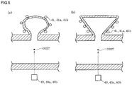
- the blackbody cavity is, e.g., a spherical or conical cavity as shown in FIG. 5(a) or FIG. 5(b) or a cavity having a shape provided by further elongating a cylindrical shape as shown in FIG. 4 (b) to realize a blackbody, and the radiation light which has entered the cavity repeats reflection or absorption in the cavity and attenuates when the blackbody cavity is provided on the wall surface facing the second radiance meter 40.
- the radiation light which has entered the cavity can be prevented from again being discharged into the kiln hood 12 from the opening end as much as possible, and a high emissivity of 0.99 or more can be provided. Consequently, since it is possible to greatly reduce the effect that the radiation light emitted from the flame of the burner 16 or the inner wall of the kiln hood 12 is reflected on the wall surface, the measurement accuracy for the radiance of the dust can be improved, and the measurement accuracy for a temperature of the object to be heated can be further enhanced.
- the cooling means can be also used. That is, for example, it is preferable to install the water cooled tube or the air cooled tube on an outer surface of the black cavity and perform the measurement in a state where the inner wall surface of the blackbody cavity is lowered to a temperature of 300 to 500°C.
- a radiance L' d , ⁇ of the dust at a wavelength ⁇ is first measured from the second radiance meter 40 provided in the cement production equipment 10a.
- the radiance L' d , ⁇ of the dust measured by the second radiance meter 40 is represented by the following Expression (1) when self-absorption and self-scattering caused due to the dust are taken into consideration.
- L d , ⁇ ′ a p , ⁇ L d , ⁇ a p , ⁇ + ⁇ p , ⁇ 1 ⁇ exp ⁇ a p , ⁇ + ⁇ p , ⁇ s d
- L d , ⁇ is a radiance of the dust
- a p , ⁇ is an absorption coefficient of the dust
- ⁇ p , ⁇ is a scattering coefficient of the dust
- s d is a length of the second radiance meter 40 in the optical axis direction in the area of dust presence.
- the radiance L d , ⁇ of the dust is obtained from a dust temperature T d based on Planck's formula which is the following Expression (2), and the absorption coefficient a p , ⁇ of the dust and the scattering coefficient ⁇ p , ⁇ of the dust are represented by the following Expression (3) and Expression (4), respectively.
- Expression (1') provided by substituting Expression (3) and Expression (4) in Expression (1) is shown below.
- a ratio (L d , ⁇ 1 /L d , ⁇ 2 ) of the radiances L d , ⁇ 1 and L d , ⁇ 2 of the dust is calculated from a ratio ( ⁇ 1 / ⁇ 2 ) of an emissivity ⁇ 1 of the dust particle at the wavelength ⁇ 1 and an emissivity ⁇ 2 of the dust particle at the wavelength ⁇ 2 .
- T C 2 1 / ⁇ 2 ⁇ 1 / ⁇ 1 In L ⁇ 1 / L ⁇ 2 + 5 ⁇ In ⁇ 1 / ⁇ 2
- the radiances L d , ⁇ 1 and L d , ⁇ 2 of the dust at the wavelength ⁇ 1 and the wavelength ⁇ 2 can be obtained by using this dust temperature T d .
- a p ⁇ N ⁇ In 1 ⁇ L d ; ⁇ ′ Ld , ⁇ Q abs , ⁇ + Q sca , ⁇ Q abs , ⁇ Q abs , ⁇ + Q sca , ⁇ s d
- Tg is a gas temperature (K) in an area of dust presence
- p density of the dust particles. It is to be noted that this Expression (8) is provided by converting N representing the number of particles per gas unit volume in the area of gas presence at an actual gas temperature into a particle mass with the use of the density of the particle after correction to 0°C and determining a resultant as dust concentration.
- a radiance L' c, ⁇ of the object to be heated 30 at the wavelength ⁇ 1 or the wavelength ⁇ 2 is measured by using the first radiance meter 20.
- this radiance L' c, ⁇ of the object to be heated 30 is represented by the following Expression (9).
- a first term on the right side in the following Expression (9) represents a radiance from the object to be heated 30 when the attenuation due to absorption and scattering of the dust is taken into consideration
- a second term on the right side represents a radiance from the dust when self-absorption and self-scattering due to the dust are taken into consideration.
- the radiance L c, ⁇ of the object to be heated 30 and the radiance L d, ⁇ of the dust are obtained from a temperature T c of the object to be heated 30 and a dust temperature T d based on Planck's formula of Expression (2), and the absorption coefficient a p, ⁇ of the dust and the scattering coefficient ⁇ p, ⁇ of the dust are represented by Expression (3) and Expression (4) respectively.
- Expression (9') provided by substituting Expression (3) and Expression (4) in Expression (9) is shown below.
- T d obtained from the radiance L' c, ⁇ of the object to be heated 30 measured at the wavelength ⁇ 1 or the wavelength ⁇ 2 by first radiance meter 20 and the radiances L' d, ⁇ 1 and L' d, ⁇ 2 of the dust measured at the two wavelengths i.e.
- the wavelengths ⁇ 1 and ⁇ 2 by the second radiance meter 40 based on Expression (5) and Expression (6), the radiance L d, ⁇ of the dust at the wavelength ⁇ 1 or the wavelength ⁇ 2 used in the measurement of the first radiance meter 20 obtained from Expression (2), and A p ⁇ N obtained from Expression (7) are substituted in Expression (10), the radiance L c, ⁇ of the object to be heated 30 can be obtained.
- the wavelength at which the radiance L' c, ⁇ of the object to be heated 30 is measured by the first radiance meter 20 using one of the wavelengths ⁇ 1 and ⁇ 2 when the radiance L' d , ⁇ of the dust is measured by the second radiance meter 40 is simple and hence desirable, but any other wavelength ⁇ 3 may be used as long as the absorption coefficient a p, ⁇ of the dust and the scattering coefficient ⁇ p, ⁇ of the dust can be additionally obtained.
- the radiance L d, ⁇ of the dust which is substituted in Expression (10) could be obtained by using T d and the wavelength ⁇ 3 in Expression (2).
- a radiance ratio (L c, ⁇ 1 /L c, ⁇ 2 ) of the object to be heated 30 can be obtained from an emissivity ratio ( ⁇ c, ⁇ 1 / ⁇ c, ⁇ 2 ) of the object to be heated without directly providing emissivities ⁇ c, ⁇ 1 and ⁇ c, ⁇ 2 of the object to be heated 30, and a temperature T c of the object to be heated 30 can be obtained from Expression (6).
- the emissivity ratio ( ⁇ c , ⁇ 1 / ⁇ c, ⁇ 2 ) can be regarded as 1.
- the radiance L' c, ⁇ of the object to be heated 30 is measured at the two wavelengths in advance, it is possible to suppress the effect that a flame of the burner 16 or radiation light emitted from the inner wall of the kiln hood 12 is reflected on the object to be heated 30 and enters the first radiance meter 20, and improve an accuracy of temperature measurement.
- the radiance L' c, ⁇ of the object to be heated 30 is measured at the two wavelengths in advance, it is possible to suppress the effect of an error in the radiance L d, ⁇ of the dust or A p • N which is caused when the radiation light emitted from the burner 16 or the inner wall of the kiln hood 12 is reflected on the wall surface in the furnace facing the second radiance meter 40 or scattered by the dust itself and enters the second radiance meter and which is calculated from a measurement value of the second radiance meter 40.
- ⁇ of the object to be heated 30 is measured at the two wavelengths.
- ⁇ at the time of measuring the radiance L' c, ⁇ of the object to be heated 30 with the use of the first radiance meter 20 using ⁇ 1 and ⁇ 2 at the time of measuring the radiance L' d, ⁇ of the dust by the second radiance meter 40 is simple and hence desirable, but combinations of other wavelengths, e.g.
- wavelengths ⁇ 4 and ⁇ 5 , wavelengths ⁇ 1 ad ⁇ 5 as well as wavelengths ⁇ 4 and ⁇ 2 can suffice as long as the absorption coefficient a p, ⁇ of the dust and the scattering coefficient ⁇ p, ⁇ of the dust can be additionally obtained.
- the radiances L d , ⁇ 1 and L d, ⁇ 2 of the dust which are substituted in Expression (12) could be replaced with the radiances L d, ⁇ 4 and L d, ⁇ 5 obtained with the use of the wavelength ⁇ 4 and the wavelength ⁇ 5 in Expression (2) at T d , and substituted.
- the temperature T c of the clinker which is the object to be heated can be obtained in the furnace having the dust therein like a rotary kiln in the cement production equipment.
- the temperature T c of the clinker, the dust temperature T d , dust concentration C d , and others may be manually calculated from the measured radiances L' c, ⁇ and L' d, ⁇ , but they may be automatically calculated by, e.g., calculating means such as a program of a computer 21 connected to outputs of the first radiance meter 20 and the second radiance meter 40.
- a measuring method according to a second embodiment of the present invention will now be described.
- this measuring method according to the second embodiment like the first embodiment, a description will be given as to an example where a temperature of an object to be heated (a clinker) which is in a high-temperature state is measured in a rotary kiln having dust therein provided in a cement production equipment.
- the measuring method as radiances of the dust used in the measurement of a temperature of the object to be heated in the first embodiment, two or more radiances measured by a plurality of second radiance meters are used.
- a dust temperature, dust concentration, and others are always constant depending on situations or the like.
- the area of dust presence is divided into two or more, and a plurality of radiances of dust in the respective divided areas are used, thereby further stabilizing a measurement accuracy.
- a cement production equipment 10b used in the second embodiment is the same as the cement production equipment 10a used in the first embodiment in a side elevation ( FIG. 3 ) .
- a top view of the cement production equipment 10b used in this second embodiment is shown in FIG. 2 .
- a first radiance meter 20 which measures a radiance of an object to be measured 30 is provided on an outer side of a wall surface of a kiln hood 12 facing an end portion of a kiln shell 11a on the downstream side and at a position facing an object to be heated 30. That is, the first radiance meter 20 is provided so that the object to be heated 30 is present on an optical axis of the first radiance meter 20.
- a plurality of second radiance meters 40a and 40b which are configured to measure two or more radiances of dust present between the object to be measured 30 and the first radiance meter 20 are provided on the outer side of a side wall surface of the kiln hood 12, i.e. , positions which do not face the object to be heated 30. That is, as regards a positional relationship between the first radiance meter 20 and the second radiance meters 40a and 40b, the second radiance meters 40a and 40b are provided at positions where optical axes of the second radiance meters 40a and 40b at least do not become parallel to, e.g.
- FIG. 2 shows an example where the two second radiance meters 40a and 40b are provided, the second radiance meters are provided in correspondence with the number of areas of dust presence divided at the time of carrying out the measuring method according to the present invention.
- this cement production equipment 10b it is desirable to likewise configure this cement production equipment 10b so that its wall surface facing the second radiance meters 40a and 40b (a wall surface on the optical axes of the second radiance meters 40a and 40b) is held at a temperature lower than that of a surrounding wall surface by cooling means 41a and 41b provided as shown in FIG. 4(a) and FIG. 4(b) . It is preferable to reduce the temperature of the wall surface to a temperature of 300 to 500°C. Additionally, it is desirable to control an emissivity of the wall surface facing the second radiance meters 40a and 40b to an emissivity much higher than 0.9 by using a material having an emissivity of 0.9 or more or providing such a blackbody cavity as shown in FIG. 5(a) or FIG. 5(b) like the first embodiment.
- radiances L' d1, ⁇ and L' d2, ⁇ of the dust at a wavelength ⁇ are first measured by the plurality of second radiance meters 40a and 40b provided in the cement production meter 10b respectively.
- the radiances L' d1, ⁇ and L' d1, ⁇ of the dust measured by the plurality of second radiance meters 40a and 40b are represented by the following Expression (13) and Expression (14), respectively.
- L d 2 , ⁇ ′ a p 2 , ⁇ L d 2 , ⁇ a p 2 , ⁇ + ⁇ p 2 , ⁇ 1 ⁇ exp ⁇ a p 2 , ⁇ + ⁇ p 2 , ⁇ s d 2
- L' d1, ⁇ and L' d2, ⁇ are radiances of dust in first and second areas of dust presence respectively
- ⁇ are absorption coefficients of dust in the first and second areas of dust presence respectively
- ⁇ p1, ⁇ and ⁇ p2 ⁇ are scattering coefficients of dust in the first and second areas of dust presence respectively
- s d1 and s d2 are lengths of the second radiance meters 40a and 40b in the optical axis direction in the first and second areas of dust presence respectively.
- the radiances L d1, ⁇ and L d2, ⁇ of the dust are obtained from dust temperatures T d1 and T d2 based on Planck's formula of Expression (2) respectively, and the absorption coefficients a p1, ⁇ and a p2, ⁇ of the dust and the scattering coefficients ⁇ p1, ⁇ and ⁇ p2, ⁇ of the dust are represented by Expression (3) and Expression (4) respectively.
- Expression (3) and Expression (4) in Expression (13) and Expression (14) respectively enables acquiring two expressions corresponding to Expression (1') in the first embodiment. Furthermore, on the basis of these expressions, it is possible to acquire expressions corresponding to Expression (5) in the first embodiment, which are the following Expression (15) and Expression (16) representing respective ratios (L' d1, ⁇ 1 /L' d1, ⁇ 2 and L' d2, ⁇ 1 /L' d2, ⁇ 2 ) of the radiances L' d1, ⁇ 1 and L' d1, ⁇ 2 , and L' d2, ⁇ 1 and L' d2, ⁇ 2 of the dust measured at two wavelengths, i.e., wavelengths ⁇ 1 and ⁇ 2 by the second radiance meters 40a and 40b respectively.
- Expression (15) and Expression (16) representing respective ratios (L' d1, ⁇ 1 /L' d1, ⁇ 2 and L' d2, ⁇ 1 /L' d2, ⁇ 2 ) of the
- the radiances L d1, ⁇ 1 and L d2, ⁇ 1 , and L d1, ⁇ 2 and L d2, ⁇ 2 of the dust at the wavelength ⁇ 1 and the wavelength ⁇ 2 can be obtained with the use of the dust temperatures T d1 and T d2 on the basis of Expression (2), respectively.
- a p 1 ⁇ N 1 In 1 ⁇ L d 1 , ⁇ ′ L d 1 , ⁇ ′ Q abs 1 , ⁇ + Q sca 1 , ⁇ Q abs 1 , ⁇ Q abs 1 , ⁇ + Q sca 1 , ⁇ S d 1
- a p 2 ⁇ N 2 In 1 ⁇ L d 2 , ⁇ ′ L d 2 , ⁇ ′ Q abs 2 , ⁇ + Q sca 2 , ⁇ Q abs 2 , ⁇ Q abs 2 , ⁇ + Q sca 2 , ⁇ S d 2
- T g1 and T g2 are gas temperatures (K) in the first and second areas of dust presence, and ⁇ 1 and ⁇ 2 are densities of the dust particles in the first and second areas of dust presence, respectively.
- a combination of wavelengths at the time of measuring the radiances L' d1, ⁇ and L' d2, ⁇ of the dust by the second radiance meters 40a and 40b may differ depending on the second radiance meters 40a and 40b and, for example, wavelengths ⁇ 1 and ⁇ 7 , or wavelengths ⁇ 6 and ⁇ 2 as well as wavelengths ⁇ 6 and ⁇ 7 may be used in the measurement using the second radiance meter 40b.
- a radiance L' c2, ⁇ of the object to be heated 30 at the wavelength ⁇ 1 or ⁇ 2 is measured by the first radiance meter 20.
- the radiance L' c2, ⁇ measured by the first radiance meter 20 is represented by the following Expression (21).
- a first term on the right side in the following Expression (21) represents a radiance L' c1, ⁇ from the object to be heated after passing through the first dust area represented by the following Expression (22) while taking the attenuation due to absorption and scattering of the dust in the second area of dust presence into consideration.
- a second term on the right side in the following Expression (21) represents a radiance from the dust in the second area of dust presence while taking self-absorption and self-scattering due to the dust into consideration.
- a first term on the right side in the following expression (22) represents a radiance from the object to be heated while taking the attenuation due to absorption and scattering of the dust in the first dust area into consideration
- a second term on the right side represents a radiance from the dust in the first area of dust presence while takin self-absorption and self-scattering due to the dust into consideration.
- L c 2 , ⁇ ′ L c 1 , ⁇ ′ exp ⁇ a p 2 , ⁇ s c 2 + a p 2 , ⁇ L d 2 , ⁇ a p 2 , ⁇ + ⁇ p 2 , ⁇ 1 ⁇ exp ⁇ a p 2 , ⁇ + ⁇ p 2 , ⁇ s c 2
- L d2, ⁇ is a radiance of the dust in the second area of dust presence
- s c2 is a length of the first radiance meter 20 in the optical axis direction in the second area of dust presence.
- a p2, ⁇ is an absorption coefficient of the dust in the second area of dust presence
- ⁇ p2 ⁇ is a scattering coefficient of the dust in the second area of dust presence.
- the radiances L d1, ⁇ and L d2, ⁇ of the dust and the radiance L c, ⁇ of the object to be heated are obtained from the dust temperatures T d1 and T d2 and the temperature T c of the object to be heated on the bases of Planck's formula of Expression (2), and the absorption coefficients a p1, ⁇ and a p2, ⁇ and the scattering coefficients ⁇ p1, ⁇ and ⁇ p2, ⁇ of the dust are represented by Expression (3) and Expression (4), respectively.
- Expression (23) represents an expression which obtains the radiance L' c1, ⁇ from the object to be heated after passing through the first area of dust presence from the radiance L' c2, ⁇ of the object to be heated 30 measured by the first radiance meter 20 by substituting Expression (3) and Expression (4) in Expression (21).
- T d2 is obtained from the radiance L' c2, ⁇ of the object to be heated 30 measured at the wavelength ⁇ 1 or the wavelength ⁇ 2 by the first radiance meter 20 and the radiances L' d2 , ⁇ 1 and L' d2, ⁇ 2 of the dust measured by the second radiance meter 40b on the basis of Expression (16) and Expression (6), and L' c1, ⁇ is obtained by substituting the radiance L d2, ⁇ of the dust at the wavelength ⁇ 1 or the wavelength ⁇ 2 used for the measurement of the first radiance meter 20 and A p2 ⁇ N 2 obtained from Expression (18) in Expression (23).
- Expression (24) represents an expression which obtains the radiance L c, ⁇ of the object to be heated 30 by substituting Expression (3) and Expression (4) in Expression (22) and modifying it.
- T d1 is obtained from the acquired L' c1, ⁇ and the radiances L' d1, ⁇ 1 and L' d1, ⁇ 2 of the dust measured by the second radiance meter 40a on the basis of Expression (15) and Expression (6), and the radiance L d1, ⁇ of the dust at the wavelength ⁇ 1 or the wavelength ⁇ 2 obtained from Expression (2) and used for the measurement of the first radiance meter 2 0 and A p1 ⁇ N 1 obtained from Expression (17) are substituted, thereby acquiring the radiance L c, ⁇ of the object to be heated 30.
- the wavelength at which the radiance L' c2, ⁇ of the object to be heated 30 is measured using either the wavelength ⁇ 1 or ⁇ 2 at the time of measuring the radiances L' d1, ⁇ and L' d2, ⁇ of the dust by the second radiance meters 40a and 40b is simple and desirable, but any other wavelength ⁇ 8 may be used as long as the absorption coefficient a p, ⁇ of the dust and the scattering coefficient ⁇ p, ⁇ of the dust can be additionally obtained.
- the radiance L d2, ⁇ of the dust which is substituted in Expression (23) can be obtained by using T d2 and the wavelength ⁇ 8 in Expression (2)
- the radiance L d1, ⁇ of the dust which is substituted in Expression (24) can be obtained by using T d2 and the wavelength ⁇ 8 in Expression (2).
- L c , ⁇ 1 ⁇ c ; ⁇ L c 1 , ⁇ ′ ⁇ Q abs 1 , ⁇ L d 1 , ⁇ Q abs 1 , ⁇ + Q sca 1 , ⁇ exp ⁇ Q abs 1 , ⁇ + Q sca 1 , ⁇ A p 1 N 1 S c 1 + Q abs , 1 , ⁇ L d 1 , ⁇ Q abs 1 , ⁇ + Q sca 1 , ⁇ .
- a radiance ratio (L c, ⁇ 1 /L c, ⁇ 2 ) of the object to be heated 30 can be obtained from an emissivity ratio ( ⁇ c, ⁇ 1 / ⁇ c, ⁇ 2 ) of the object to be heated 30 without directly giving emissivities ⁇ c, ⁇ 1 and ⁇ c, ⁇ 2 of the object to be heated 3 0, and the temperature T c of the object to be heated 3 0 can be acquired from Expression (6).
- the emissivity ratio ( ⁇ c, ⁇ 1 / ⁇ c, ⁇ 2 ) can be considered as 1.
- ⁇ of object to be heated 30 is measured at two wavelengths in advance, the effect that a flame of the burner 16 or radiation light emitted from the inner wall of the kiln hood 12 is reflected on the object to be heated 30 and enters the first radiance meter 20 can be suppressed, and an accuracy of the temperature measurement can be improved.
- wavelengths ⁇ at the time of measuring the radiance L' c2 ⁇ of the object to be heated 30 by using the first radiance meter 20, using ⁇ 1 and ⁇ 2 at the time of measuring the radiances L' d1, ⁇ and L' d2, ⁇ of the dust is simple and desirable, but combinations of other wavelengths, e.g., wavelengths ⁇ 1 and ⁇ 10 , wavelengths ⁇ 9 ad ⁇ 2 as well as wavelengths ⁇ 9 and ⁇ 10 can suffice as long as the absorption coefficient a p, ⁇ of the dust and the scattering coefficient ⁇ p, ⁇ of the dust can be additionally obtained.
- L d2, ⁇ which is substituted in Expression (23) is calculated from T d2 at the wavelength ⁇ 9 and the wavelength ⁇ 10 and substituted on the basis of Expression (2), and the radiance L d1, ⁇ 1 and L d1, ⁇ 2 of the dust which are substituted in Expression (25) could be replaced with the radiances L d1, ⁇ 9 and L d1, ⁇ 10 obtained with the use of the wavelength ⁇ 9 and the wavelength ⁇ 10 from T d1 and substituted on the basis of Expression (2).
- the temperature T c of the clinker which is the object to be heated can be obtained in the furnace having the dust therein like a rotary kiln in the cement production equipment.
- a measurement accuracy can be improved.
- the temperature T c of the clinker, the dust temperatures T d1 and T d2 , dust concentrations C d1 and C d2 , and others may be manually calculated from the measured radiances L' c, ⁇ , L' d1, ⁇ , and L' d2, ⁇ , but they may be automatically calculated by, e.g., calculating means such as a program of a computer 21 connected to outputs of the first radiance meter 20 and the second radiance meters 40a and 40b.
- the measuring method according to the present invention is not restricted to this example, and the temperature measuring method according to the present invention can be preferably used if it is an object in an atmosphere where dust is present.
- the object to be heated there are an object to be heated present in high-temperature furnaces (heating, smelting, refinement, firing, reactions, and others) other than a rotary kiln, a heat exchange tube in a boiler, and a solid or a liquid flowing through a duct as well as a heat transfer pipe or a partition wall in a heat exchanger.
- the object which is a temperature measurement target is not restricted to one having a high temperature above 1000°C like a clinker, and it may be one having approximately hundreds °C.
- a temperature T c of an object to be heated 1450°C
- an emissivity ⁇ c, ⁇ of the object to be heated is 0.9 ( ⁇ 1 , ⁇ 2 )
- a dust temperature T d 1000°C
- dust concentration C d 100g/m 3 N (N means that a temperature of a dust-containing gas is 0°C and a pressure is an atmospheric pressure)
- a radius rp of a dust particle 20 ⁇ m
- an emissivity ⁇ of the dust particle is 0.9 ( ⁇ 1 , ⁇ 2 )
- a length s d of an area of dust presence when a radiance of the dust is measured by the second radiance meter 40 is 5 m
- a length s c of the area of dust presence when a radiance of the object to be heated 3 0 is measured by the first radiance meter 20 is 5 m
- cooling means 41 was provided, and a second radiance meter 40 was installed at a positon facing a wall surface cooled to 300°C by the cooling means 41.
- the cooling means 41 was installed as shown in FIG. 4 (b) by a method of providing a cylindrical concave portion which has an opening end in a wall surface and protrudes toward the outer side, and by winding a water cooled tube as the cooling means 41 on an outer periphery of the concave portion.
- a cylinder length (a height) of the cylindrical concave portion was adjusted to provide a blackbody cavity, an emissivity of the wall surface was set to 0.999, and radiation light entered the blackbody cavity from a furnace inner wall surface of 1200°C surrounding this cavity.
- Table 1 shows a measurement result of temperatures of the object to be heated when an emissivity of a wall surface facing the second radiance meter 40 was changed when other conditions remained the same to see an effect of the emissivity of the wall surface.
- an emissivity 0. 7 shows a case where the facing wall surface was made of a refractory and measurement was performed
- an emissivity 0. 9 shows a case where a blackbody coating was further applied to the wall surface made of the refractory and measurement was performed.
- an emissivity 0.999 corresponds to a result of providing the blackbody cavity and performing measurement.
- each numerical value in parentheses represents a deviation from 1450°C which is the temperature of the object to be heated.
- cooling means 41a and 41b were provided, and the second radiance meters 40a and 40b were installed at positons facing a wall surface cooled to 300°C by the cooling means 41a and 41b.
- both of the two cooling means 41a and 41b were installed as shown in FIG 4(b) by a method of providing a cylindrical concave portion which has an opening end in a wall surface and protrudes toward the outer side, and by winding a water cooled tube as the cooling means 41a and 41b on an outer periphery of the concave portion.
- the cylindrical concave portion was made to be a blackbody cavity by adjusting a cylinder length (a height), and an emissivity of the wall surface was set to 0.999.
- the cooling means 41 was provided, and the second radiance meter 40 was installed at a positon facing a wall surface cooled to 300°C by the cooling means 41.
- the cooling means 41 was installed as shown in FIG. 4 (b) by a method of providing a cylindrical concave portion which has an opening end in a wall surface and protrudes toward the outer side, and by winding a water cooled tube as the cooling means 41 on an outer periphery of the concave portion.
- the cylindrical concave portion was made to be a blackbody by adjusting a cylinder length (a height), and an emissivity of the wall surface was set to 0.999.
- deviations in the measurement performed at two positions in the area of dust presence and the measurement performed at one position in the same on the basis of this method and a deviation in the measurement on the basis of the existing technology are 0°C, -39°C, and -196°C respectively, and it has been revealed that this method has a higher accuracy than that of the existing technology and that, if the dust temperature, the dust concentration, the radius of the dust particle, and others have distributions in the area of dust presence, increasing the number of positions at which the radiance of dust is measured enables enhancing a temperature measurement accuracy.
- the present invention can be preferably used in measurement of a temperature of an object to be heated like a clinker having a high-temperature mainly in a furnace having dust therein like a rotary kiln in a cement production equipment.
Landscapes
- Physics & Mathematics (AREA)
- General Physics & Mathematics (AREA)
- Spectroscopy & Molecular Physics (AREA)
- Engineering & Computer Science (AREA)
- Mechanical Engineering (AREA)
- General Engineering & Computer Science (AREA)
- Radiation Pyrometers (AREA)
- Waste-Gas Treatment And Other Accessory Devices For Furnaces (AREA)
- Muffle Furnaces And Rotary Kilns (AREA)
- Furnace Details (AREA)
- Measuring Temperature Or Quantity Of Heat (AREA)
Abstract
Description
- The present invention relates to a method for measuring a temperature of an object in an atmosphere where dust presents, e.g., an object to be heated or the like having a high temperature in a furnace where dust presents such as a rotary kiln provided in a cement production equipment. This International Application which claims priority based on Japanese Patent Application No.
2014-053172 filed on March 17, 2014 2014-053172 - Generally, in a furnace which has high dust concentration and where a continuous treatment is performed like a rotary kiln provided in a cement production equipment, a radiation thermometer or the like which can measure a temperature in a contactless manner is used for temperature measurement of an object to be heated. This radiation thermometer is widely used in a baking furnace other than the rotary kiln or high-temperature processes.
- However, the radiation thermometer has a problem that presence of dust between the object to be heated which is a measurement target and an observer leads to an influence of attenuation of radiation light caused by the dust and the radiation light from the dust itself, and a temperature of the object to be heated cannot be accurately measured. A two-color thermometer known as a non-contact thermometer obtains a temperature from a radiance ratio at two wavelengths, and this two-color thermometer can ignore an influence of attenuation of the radiation light caused by the dust which does not change the radiance ratio, but it cannot ignore an influence of the radiation light from the dust which changes the radiance ratio.
- The above-described problem according to the temperature measurement in the furnace having high dust concentration can likewise occur in other baking furnaces than the cement firing furnace as a matter of course. To eliminate such a problem, for example, a temperature measuring method which enables assuredly measuring a liquid level temperature of molten slag in a furnace having high soot concentration is disclosed (see, e.g., Patent Literature 1). According to this temperature measuring method, of radiant light radiated from a liquid level of molten slag accommodated in a furnace, radiant light in an intermediate-infrared region or a far-infrared region is concentrated on a photoelectric element, an output voltage having an amplitude corresponding to intensity of the incoming radiant light is generated from the photoelectric element, and the liquid level temperature of the molten slag is determined on the basis of this output voltage value and Planck's law of radiation. Further, according to this temperature measuring method, radiant lights having two or more different wavelengths are used.
- Furthermore, there is disclosed a flame light emission measuring apparatus using a condensing optical system in local measurement which is generally adopted to measure a fine structure of a flame (see, e.g., Patent Literature 2). This measuring apparatus is characterized by having a condensing optical system constituted of a single optical system which condenses light emission from a plurality of measuring points of a flame onto corresponding condensing points on a condensing surface and a light emission measuring system in which the light emission from the plurality of measuring points condensed on the condensing points respectively is measured.
-
- Patent Document 1: Japanese Unexamined Patent Application Publication No.
2001-249049 claim 1, claim 2, claim 3, paragraph [0001]) - Patent Document 2: Japanese Unexamined Patent Application Publication No.
2000-111398 claim 1, paragraph - However, according to the method disclosed in
Patent Literature 1 of the prior art, dust as a target has a particle diameter of 1 to 2 µm, and it is much finer than dust in the cement firing furnace and the like. Thus, this method cannot be directly applied to the dust in the cement firing furnace and the like and used for temperature measurement of clinkers. Likewise, it cannot be applied when a particle diameter of dust is not fine as described above even in case of measuring a temperature of a solid matter, a liquid, or the like flowing through a duct such as an object to be heated present in high-temperature furnaces (heating, smelting, refinement, firing, reactions, and others) other than a rotary kiln or a heat exchange tube in a boiler as well as a heat transfer pipe or a partition wall in a heat exchanger. Further, like the local measurement using the condensing optical system disclosed in Patent Literature 2, since a technique of simply reducing a volume to be measured cannot eliminated the effect of dust on an optical path and others, it cannot be directly applied to the method for measuring a temperature and others of clinkers in the cement firing furnace or the like having high dust concentration. - Thus, there has been demanded development of a measuring method which can be applied to measurement of a clinker temperature and others of the cement firing furnace and is more accurate than a conventional method using two-color thermometer.
- It is an object of the present invention to provide a measuring method which enables more accurately measuring an obj ect in an atmosphere where dust is present, e. g. , an obj ect to be heated having a high temperature in a furnace where dust is present, e.g., a rotary kiln provided in a cement production equipment.
- According to a first aspect of the present invention, there is provided a method for measuring a temperature of an object, the method using a first radiance meter which is provided to face the object in an atmosphere where dust is present and measures a radiance of the object and a second radiance meter which is provided without facing the object and measures a radiance of the dust present between the object and the first radiance meter so that a temperature of the object is measured from the radiance of the object measured by the first radiance meter and the radiance of the dust present between the object and the first radiance meter measured by the second radiance meter.
- According to a second aspect of the present invention, there is provided the invention based on the first aspect which is characterized in that the radiance of the dust is measured at two wavelengths.
- According to a third aspect of the present invention, there is provided the invention based on the first or second aspect which is characterized in that, at the time of measuring the radiance of the dust, the measurement is performed in a state where a temperature of a wall surface facing the second radiance meter is lowered by cooling means.
- According to a fourth aspect of the present invention, there is provided the invention based on the first to third aspects which is characterized in that, at the time of measuring the radiance of the dust, an emissivity of the wall surface facing the second radiance meter is set to 0.9 or more.
- According to a fifth aspect of the present invention, there is provided the invention based on the fourth aspect which is characterized in that, at the time of measuring a radiance of the dust, a blackbody cavity is provided in the wall surface facing the second radiance meter.
- According to a sixth aspect of the present invention, there is provided the invention based on the first to fifth aspects characterized in that the radiance of the object is measured at two wavelengths.
- According to a seventh aspect of the present invention, there is provided the invention based on the first to sixth aspects characterize in that a plurality of radiance meters are used as the second radiance meter to measure two or more radiances of the dust, and the measurement is made from the radiance of the object measured by the first radiance meter and the two or more radiances of the dust present between the object and the first radiance meter and measured by the plurality of second radiance meters.
- The method according to the first aspect of the present invention uses the first radiance meter which is provided to face an object in an atmosphere where dust is present and measures a radiance of the object and the second radiance meter which is provided without facing the object and measures a radiance of dust present between the object and the first radiance meter. This measuring method adopts a method which uses radiance meters different from a radiance meter which measures the radiance of the object and measures the radiance of the dust from other angles. Consequently, the effect of the dust at the time of measuring a temperature of the object can be reflected as a more accurate numerical value, and the accuracy can be further improved.
- According to the method based on the second aspect of the present invention, the radiance of the dust is measured at two wavelengths. As the radiance of the dust is measured at the two wavelengths, a later-described load (Ap·N) of the dust as well as a temperature and concentration of the dust can be more accurately measured.
- According to the method based on the third aspect of the present invention, the radiance of the dust is measured in a state where a temperature of the wall surface facing the second radiance meter is lowered by the cooling means. Consequently, the effect of radiation from the wall surface can be lowered, a measurement accuracy for the radiance of the dust can be improved, and a measurement accuracy for an object temperature can be enhanced.
- According to the method based on the fourth aspect of the present invention, at the time of measuring the radiance of the dust, setting an emissivity of the wall surface facing the second radiance meter to 0.9 or more enables to reduce the effect that radiation light emitted from a high-temperature object other than the dust, e.g., a burner or a furnace wall is reflected on the wall surface and enters the radiance meters, improve the measurement accuracy for the radiance of the dust, and further enhance the measurement accuracy for an object temperature.
- According to the method based on the fifth aspect of the present invention, at the time of measuring the radiance of the dust, providing the blackbody cavity in the wall surface facing the second radiance meter enables to reduce the effect that the radiation light emitted from a high-temperature object other than the dust, e.g., a burner or a furnace wall is reflected on the wall surface and enters the radiance meters, improve the measurement accuracy for the radiance of the dust, and further enhance the measurement accuracy for an object temperature.
- According to the method based on the sixth aspect of the present invention, measuring the radiance of the object is measured at two wavelengths, a temperature can be measured by giving an emissivity ratio of the object at the two wavelengths rather than directly giving an emissivity of the object, and the effect that the radiation light emitted from a high-temperature object other than the object which is a temperature measurement target is reflected on the object and enters the radiance meters can be suppressed, and the accuracy for temperature measurement can be improved. Likewise, as regards the radiance of the dust measured by the second radiance meter, when the radiance of the object is measured at two wavelengths, it is possible to suppress the effect that the radiation light emitted from a high-temperature object other than the dust, e.g., a burner or a furnace wall is reflected on the wall surface in the furnace facing the second radiance meter or scattered by the dust itself and enters the second radiance meter.
- According to the method based on the seventh aspect of the present invention, as the second radiance meter for use in measurement of the radiance of the dust, a plurality of radiance meters are used, two or more radiances of the dust measured by them are reflected in the radiance of the object measured by the first radiance meter, and an object temperature is measured. Consequently, as compared with a case where one radiance of the dust measured by the single second radiance meter is used, a temperature of the object can be more accurately measured.
-
-
FIG. 1 is a top view schematically showing an outline of a cement production equipment used in a first embodiment according to the present invention; -
FIG. 2 is a top view schematically showing an outline of a cement production equipment used in a second embodiment according to the present invention; -
FIG. 3 is a side elevation schematically showing an outline of a cement production equipment used in embodiment according to the present invention; -
FIG. 4 is a schematic view showing an example of cooling means provided in the cement production equipment used in embodiments according to the present invention; -
FIG. 5 is a schematic view showing an example of a blackbody cavity provided in the cement production equipment used in embodiments according to the present invention; -
FIG. 6 is a graph showing transitions of measurement values involved in changes in a dust temperature Td in Example 1; and -
FIG. 7 is a graph showing transitions of measurement values involved in changes in dust concentration Cd in Example 1. - Modes for carrying out the present invention will now be described with reference to the drawings. It is to be noted that like reference numerals denote like components and others in
FIG. 1 to FIG. 3 . It is to be noted that, in this specification, dust means a dust group formed when a plurality of dust particles suspended in a gas gather with predetermined concentration, and radiance, an absorption coefficient, a scattering coefficient, absorption efficiency, scattering efficiency, and concentration of the dust mean values of the dust group in an area of dust presence, respectively. Furthermore, the dust particle means each dust particle included in the dust group, and an emissivity, density, a geometrical cross section, and a radius of the dust particle means average values of individual dust particles included in the dust group in the area of dust presence. A dust temperature means an average value of temperatures of the individual dust particles included in the dust group in the area of dust presence. - A measuring method according to a first embodiment of the present invention will now be described on the basis of an example where a temperature of an object to be heated (a clinker) in a high-temperature state is measured in the presence of high-concentration dust in a rotary kiln provided in a cement production equipment.
- An apparatus shown in
FIG. 3 is an example of a cement production equipment preferable for carrying out the measuring method according to the present invention, and thiscement production equipment 10a includes arotary kiln 11 and akiln hood 12 connected with therotary kiln 11. Therotary kiln 11 is configured to fire a cement raw material to manufacture a clinker, and apreheater 14 is provided on the upstream side of therotary kiln 11. Thepreheater 14 preheats the cement raw material pulverized by a non-illustrated raw material mill to a predetermined temperature so that the cement raw material can be readily fired by therotary kiln 11 at a later step. Thepreheater 14 is constituted by mounting many cyclones on a multistory steel frame stand. Therotary kiln 11 has a laterally-facing cylindrical kiln shell 11a which is slightly downwardly inclined toward the downstream side, and aburner 16 which faces a kiln tail is provided at an end portion of the kiln shell 11a on the downstream side. The cement raw material is preliminary fired while flowing down through each cyclone of thepreheater 14, and then the cement raw material flows into the kiln tail portion of therotary kiln 11. A refractory 11b is applied to an inner wall surface of the kiln shell 11a. The kiln shell 11a fires the cement raw material supplied from thepreheater 14 by burner heating, which uses a heavy oil or pulverized coal as a fuel, to provide a clinker while rotating in a circumferential direction (in a periaxial direction), and carries it to the burner side. - The
kiln hood 12 has an upstream end connected to a burner side end portion of therotary kiln 11 and a downstream end connected to aclinker cooler 13. The clinker of approximately 1200 to 1500°C which is discharged from the burner side end portion of therotary kiln 11 and supplied to the upstream side of thekiln hood 12 is cooled by air of 20 to 30°C supplied from a coolingfan 18 connected to theclinker cooler 13. A plurality ofplates 13b are laid on a floor surface of this clinker cooler 13 from the upstream side toward the downstream side, and the lump-like clinker discharged from the burner side end portion of therotary kiln 11 falls onto theplates 13b on the upstream side. Each of the plurality ofplates 13b reciprocates in a front-and-back direction to sequentially guide the clinker placed on an upper surface thereof to theplate 13b on the downstream side. Thus, a clinker layer which is carried on the plurality ofplates 13b from the upstream side toward the downstream side is formed in theclinker cooler 13, and the air supplied from the coolingfan 18 passes between the plurality ofplates 13b from the lower side of the plurality ofplates 13b to cool the clinker. It is to be noted that the cooled clinker is discharged from the downstream side end portion of theclinker cooler 13, and the clinker discharged from the downstream side end portion is stored in aclinker silo 19. Moreover, the air which is supplied from the coolingfan 18, passes between the plurality ofplates 13b, and further passes through the clinker layer to cool the clinker flows toward the upstream side above the clinker layer and is supplied to therotary kiln 11 as combustion air in theburner 16 as indicated by arrows of a broken line inFIG. 3 . - Additionally, as shown in
FIG. 1 andFIG. 3 , in thiscement production equipment 10a, to carry out the measuring method according to the present invention, afirst radiance meter 20 which measures a radiance of an object to be heated 30 is provided on an outer side of a wall surface of thekiln hood 12 facing the downstream side end portion of the kiln shell 11a and at a position facing the object to be heated 30. That is, thefirst radiance meter 20 is provided so that the object to be heated 30 is present on an optical axis of thefirst radiance meter 20. As an example of an apparatus that measures a radiance, in addition to a radiance meter or a spectral radiance meter, there is an apparatus which is a combination of a radiation thermometer and an arithmetic apparatus and converts a temperature measurement value of the radiation thermometer into luminance by using Planck's formula which is a later-described Expression (2). Further, considering a case where the radiance is measured at two different wavelengths, it is desirable for thefirst radiance meter 20 and later-describedsecond radiance meters - On the other hand, as shown in
FIG. 1 , thesecond radiance meter 40 which measures a radiance of dust present between the object to be heated 30 and thefirst radiance meter 20 is provided on the outer side of the side wall surface of thekiln hood 12, i.e., a position which does not face the object to be heated 30. That is, as regards a positional relationship between thefirst radiance meter 20 and thesecond radiance meter 40, thesecond radiance meter 40 is provided at a position where an optical axis of thesecond radiance meter 40 is not parallel to at least an optical axis of thefirst radiance meter 20. As a position at which thesecond radiance meter 40 is provided gets closer to a position at which the optical axis of thesecond radiance meter 40 is parallel to the optical axis of thefirst radiance meter 20, for example, radiation light from the object to be heated 30 enters thesecond radiance meter 40, and highly accurate measurement of the radiance of the dust, which is an original goal, becomes difficult in some situations. When thesecond radiance meter 40 is provided in this way to perform measurement and gauging, an accurate temperature of the object to be heated 30 can be measured while eliminating the effect of dust. It is desirable to set a position at which thesecond radiance meter 40 is installed in a height direction y to a position at which the optical axis of thissecond radiance meter 40 crosses the optical axis of thefirst radiance meter 20. Furthermore, it is desirable to set a position at which thesecond radiance meter 40 is installed in a lateral direction x (an optical axis direction of the first radiance meter 20) to a position running through an intermediate point (Sc/2) in a lateral direction x (the optical axis direction of the first radiance meter 20) in an area of dust presence. Consequently, an average dust temperature and dust concentration in the area of dust presence can be reflected in the measurement of a temperature of the object to be heated, and the measurement accuracy can be further improved. - Moreover, it is desirable to hold the wall surface facing the second radiance meter 40 (the wall surface present on the optical axis of the second radiance meter 40) at a temperature lower than a temperature of a surrounding wall surface by the cooling means 41. Consequently, the effect of the radiation light entering the
second radiance meter 40 from the wall surface can be eliminated, and the radiance of the dust can be more accurately measured. In general, in the cement equipment, although a temperature of the inner wall surface in thekiln hood 12 increases to approximately 1500°C, it is desirable to perform the measurement in a state where the temperature of the wall surface is lowered to a temperature of 300 to 500°C. Although the cooling means 41 is not restricted in particular, for example, as shown inFIG. 4 (a) , there is a water cooled tube or an air cooled tube buried immediately below the wall surface from the outer side. Additionally, for example, as shown inFIG. 4(b) , a cylindrical concave portion which has an opening end in the wall surface and protrudes toward the outer side may be provided, and the water cooled tube or the air cooled tube may be wound on an outer periphery of the concave portion. It is to be noted that, when the concave portion or the like is provided at a position facing thesecond radiance meter 40 as shown inFIG. 4(b) , the wall surface facing thesecond radiance meter 40 means an inner wall surface of the concave portion. Consequently, the effect of radiation from the wall surface can be reduced, the measurement accuracy for the radiance of the dust can be improved, and hence the measurement accuracy for a temperature of the object to be heated can be further enhanced. - Further, when radiation light emitted from a flame of the
burner 16 or the inner wall of thekiln hood 12 is reflected on the wall surface and enters thesecond radiance meter 40, the measurement accuracy is lowered. Thus, it is desirable to control an emissivity of the wall surface to 0.9 or more so that the effect of the reflection of the radiation light can be reduced. Consequently, the measurement accuracy for the radiance of the dust can be improved, and hence the measurement accuracy for a temperature of the object to be heated can be further enhanced. It is to be noted that, as a method for controlling the emissivity to 0.9 or more, when substances having emissivity of 0.9 or more, for example, a metal having an oxidized surface, a metal having fine irregularities on a surface thereof, a metal having a blackbody coating material applied thereto, a refractory, and the like are used and placed on the wall surface, the wall surface can be made of a material having desired emissivity. - Furthermore, in place of using the specific material, a blackbody cavity using the wall surface as an opening end may be installed. The blackbody cavity is, e.g., a spherical or conical cavity as shown in
FIG. 5(a) or FIG. 5(b) or a cavity having a shape provided by further elongating a cylindrical shape as shown inFIG. 4 (b) to realize a blackbody, and the radiation light which has entered the cavity repeats reflection or absorption in the cavity and attenuates when the blackbody cavity is provided on the wall surface facing thesecond radiance meter 40. Thus, the radiation light which has entered the cavity can be prevented from again being discharged into thekiln hood 12 from the opening end as much as possible, and a high emissivity of 0.99 or more can be provided. Consequently, since it is possible to greatly reduce the effect that the radiation light emitted from the flame of theburner 16 or the inner wall of thekiln hood 12 is reflected on the wall surface, the measurement accuracy for the radiance of the dust can be improved, and the measurement accuracy for a temperature of the object to be heated can be further enhanced. Moreover, to further reduce the effect of radiation from the blackbody cavity, the cooling means can be also used. That is, for example, it is preferable to install the water cooled tube or the air cooled tube on an outer surface of the black cavity and perform the measurement in a state where the inner wall surface of the blackbody cavity is lowered to a temperature of 300 to 500°C. - In the measuring method according to the first embodiment of the present invention, a radiance L'd, λ of the dust at a wavelength λ is first measured from the
second radiance meter 40 provided in thecement production equipment 10a. The radiance L'd, λ of the dust measured by thesecond radiance meter 40 is represented by the following Expression (1) when self-absorption and self-scattering caused due to the dust are taken into consideration. -

second radiance meter 40 in the optical axis direction in the area of dust presence. - It is to be noted that the radiance Ld, λ of the dust is obtained from a dust temperature Td based on Planck's formula which is the following Expression (2), and the absorption coefficient ap, λ of the dust and the scattering coefficient σp, λ of the dust are represented by the following Expression (3) and Expression (4), respectively.
-

-

-


- Here, Expression (1') provided by substituting Expression (3) and Expression (4) in Expression (1) is shown below.
-

- Based on Expression (1'), a ratio (L'd,λ1/L'd,λ2) of radiances L'd,λ1 and L'd,λ2 of the dust measured at two wavelengths, i.e., wavelengths λ1 and λ2 by the
second radiance meter 40 is represented by the following Expression (5). -

- Based on Expression (5), a ratio (Ld,λ1/Ld,λ2) of the radiances Ld,λ1 and Ld,λ2 of the dust is calculated from a ratio (ξλ1/ξλ2) of an emissivity ξλ1 of the dust particle at the wavelength λ1 and an emissivity ξλ2 of the dust particle at the wavelength λ2.
- On the other hand, an approximate expression of the following Expression (6) which can obtain a temperature T from the ratio (Ld,λ1/Ld,λ2) of the radiances at two wavelengths, i.e., the wavelengths λ1 and λ2 is derived from Planck's formula of Expression (2). Further, a value of Ld,λ1/Ld,λ2 is substituted in this Expression (6) to obtain a dust temperature Td.
-

- Then, based on Expression (2), the radiances Ld,λ1 and Ld,λ2 of the dust at the wavelength λ1 and the wavelength λ2 can be obtained by using this dust temperature Td.
- Furthermore, when either radiance Ld, λ1 or Ld,λ2 is substituted in the following Expression (7) provided by modifying Expression (1'), Ap·N can be obtained. Moreover, an average value of Ap·N obtained by substituting the radiances Ld, λ1 and Ld,λ2 in Expression (7) respectively may be used.
-

- Moreover, since Ap can be obtained by giving a radius rp of the particle diameter, N can be obtained, and dust concentration Cd is also obtained based on the following Expression (8). It is to be noted that when the radius rp of the dust particle is not clear or when it varies depending on situations, the accurate radius rp of the dust particle cannot be given, and the accurate dust concentration Cd cannot be obtained, but measurement values of a temperature of the object to be heated or a temperature of the dust which are the goal in this method are not affected, and Ap·N can be considered to correspond to a load of the dust and can be exploited in, e.g., control of the furnace.
-

- Aside from the measurement of the radiance Ld,λ of the dust using the
second radiance meter 40, a radiance L'c,λ of the object to be heated 30 at the wavelength λ1 or the wavelength λ2 is measured by using thefirst radiance meter 20. Considering attenuation due to absorption and scattering of the dust and the radiance from the dust, this radiance L'c,λ of the object to be heated 30 is represented by the following Expression (9). A first term on the right side in the following Expression (9) represents a radiance from the object to be heated 30 when the attenuation due to absorption and scattering of the dust is taken into consideration, and a second term on the right side represents a radiance from the dust when self-absorption and self-scattering due to the dust are taken into consideration. -

first radiance meter 20 in the optical axis direction in the area of dust presence. - Moreover, the radiance Lc,λ of the object to be heated 30 and the radiance Ld,λ of the dust are obtained from a temperature Tc of the object to be heated 30 and a dust temperature Td based on Planck's formula of Expression (2), and the absorption coefficient ap,λ of the dust and the scattering coefficient σp,λ of the dust are represented by Expression (3) and Expression (4) respectively.
- Here, Expression (9') provided by substituting Expression (3) and Expression (4) in Expression (9) is shown below.
-

- Additionally, when Expression (9') is modified, the following Expression (10) is derived.
-

- Further, when Td obtained from the radiance L'c,λ of the object to be heated 30 measured at the wavelength λ1 or the wavelength λ2 by
first radiance meter 20 and the radiances L'd,λ1 and L'd,λ2 of the dust measured at the two wavelengths, i.e. , the wavelengths λ1 and λ2 by thesecond radiance meter 40 based on Expression (5) and Expression (6), the radiance Ld,λ of the dust at the wavelength λ1 or the wavelength λ2 used in the measurement of thefirst radiance meter 20 obtained from Expression (2), and Ap·N obtained from Expression (7) are substituted in Expression (10), the radiance Lc,λ of the object to be heated 30 can be obtained. - It is to be noted that, as the wavelength at which the radiance L'c,λ of the object to be heated 30 is measured by the
first radiance meter 20, using one of the wavelengths λ1 and λ2 when the radiance L'd,λ of the dust is measured by thesecond radiance meter 40 is simple and hence desirable, but any other wavelength λ3 may be used as long as the absorption coefficient ap,λ of the dust and the scattering coefficient σp,λ of the dust can be additionally obtained. In such a case, the radiance Ld,λ of the dust which is substituted in Expression (10) could be obtained by using Td and the wavelength λ3 in Expression (2). - Furthermore, when this radiance Lc,λ of the object to be heated 30 is substituted in the following Expression (11) which is an inverse function of Planck's formula of Expression (2), the temperature Tc of the object to be heated 30 can be obtained.
-

- It is to be noted that, at the time of measuring the radiance L'c,λ of the object to be heated 30 by the
first radiance meter 20, measuring the radiances L'c,λ1 and L'c,λ2 of the object to be heated 3 0 at the two wavelengths, i.e., the wavelengths λ1 and λ2 in advance enables deriving the following Expression (12) based on Expression (10). -

- Consequently, a radiance ratio (Lc,λ1/Lc,λ2) of the object to be heated 30 can be obtained from an emissivity ratio (εc,λ1/εc,λ2) of the object to be heated without directly providing emissivities εc,λ1 and εc,λ2 of the object to be heated 30, and a temperature Tc of the object to be heated 30 can be obtained from Expression (6). In general, when the wavelengths λ1 and λ2 are close to each other, the emissivity ratio (εc,λ1/εc,λ2) can be regarded as 1. Further, when the radiance L'c,λ of the object to be heated 30 is measured at the two wavelengths in advance, it is possible to suppress the effect that a flame of the
burner 16 or radiation light emitted from the inner wall of thekiln hood 12 is reflected on the object to be heated 30 and enters thefirst radiance meter 20, and improve an accuracy of temperature measurement. Likewise, in a case where the radiance L'c,λ of the object to be heated 30 is measured at the two wavelengths in advance, it is possible to suppress the effect of an error in the radiance Ld,λ of the dust or Ap•N which is caused when the radiation light emitted from theburner 16 or the inner wall of thekiln hood 12 is reflected on the wall surface in the furnace facing thesecond radiance meter 40 or scattered by the dust itself and enters the second radiance meter and which is calculated from a measurement value of thesecond radiance meter 40. That is because the effect of various factors can be reduced since the calculation is made with the use of the ratio rather than an absolute value of the radiance when the radiance L'c,λ of the object to be heated 30 is measured at the two wavelengths. Here, as the wavelengths λ at the time of measuring the radiance L'c,λ of the object to be heated 30 with the use of thefirst radiance meter 20, using λ1 and λ2 at the time of measuring the radiance L'd,λ of the dust by thesecond radiance meter 40 is simple and hence desirable, but combinations of other wavelengths, e.g. , wavelengths λ4 and λ5, wavelengths λ1 ad λ5 as well as wavelengths λ4 and λ2 can suffice as long as the absorption coefficient ap,λ of the dust and the scattering coefficient σp,λ of the dust can be additionally obtained. In case of the wavelengths λ4 and λ5, the radiances Ld, λ1 and Ld,λ2 of the dust which are substituted in Expression (12) could be replaced with the radiances Ld,λ4 and Ld,λ5 obtained with the use of the wavelength λ4 and the wavelength λ5 in Expression (2) at Td, and substituted. - In the measuring method according to the first embodiment of the present invention, the temperature Tc of the clinker which is the object to be heated can be obtained in the furnace having the dust therein like a rotary kiln in the cement production equipment. It is to be noted that the temperature Tc of the clinker, the dust temperature Td, dust concentration Cd, and others may be manually calculated from the measured radiances L'c,λ and L'd,λ, but they may be automatically calculated by, e.g., calculating means such as a program of a
computer 21 connected to outputs of thefirst radiance meter 20 and thesecond radiance meter 40. - A measuring method according to a second embodiment of the present invention will now be described. As regards this measuring method according to the second embodiment, like the first embodiment, a description will be given as to an example where a temperature of an object to be heated (a clinker) which is in a high-temperature state is measured in a rotary kiln having dust therein provided in a cement production equipment.
- In the measuring method according to the second embodiment, as radiances of the dust used in the measurement of a temperature of the object to be heated in the first embodiment, two or more radiances measured by a plurality of second radiance meters are used. In an area of dust presence in a furnace in the cement production equipment or the like, it cannot be said that a dust temperature, dust concentration, and others are always constant depending on situations or the like. Thus, in this second embodiment, the area of dust presence is divided into two or more, and a plurality of radiances of dust in the respective divided areas are used, thereby further stabilizing a measurement accuracy.
- A
cement production equipment 10b used in the second embodiment is the same as thecement production equipment 10a used in the first embodiment in a side elevation (FIG. 3 ) . On the other hand, a top view of thecement production equipment 10b used in this second embodiment is shown inFIG. 2 . - As shown in
FIG. 2 andFIG. 3 , in thiscement production equipment 10b, like thecement equipment 10a used in the first embodiment, afirst radiance meter 20 which measures a radiance of an object to be measured 30 is provided on an outer side of a wall surface of akiln hood 12 facing an end portion of a kiln shell 11a on the downstream side and at a position facing an object to be heated 30. That is, thefirst radiance meter 20 is provided so that the object to be heated 30 is present on an optical axis of thefirst radiance meter 20. - On the other hand, as shown in
FIG. 2 , a plurality ofsecond radiance meters first radiance meter 20 are provided on the outer side of a side wall surface of thekiln hood 12, i.e. , positions which do not face the object to be heated 30. That is, as regards a positional relationship between thefirst radiance meter 20 and thesecond radiance meters second radiance meters second radiance meters first radiance meter 20 for the above-described reason. AlthoughFIG. 2 shows an example where the twosecond radiance meters - It is desirable to set positions at which the plurality of
second radiance meters second radiance meters first radiance meter 20. Furthermore, it is desirable to set positions in a lateral direction x (an optical axis direction of the first radiance meter 20) to positions at which the optical axes of thesecond radiance meters - Moreover, it is desirable to likewise configure this
cement production equipment 10b so that its wall surface facing thesecond radiance meters second radiance meters FIG. 4(a) and FIG. 4(b) . It is preferable to reduce the temperature of the wall surface to a temperature of 300 to 500°C. Additionally, it is desirable to control an emissivity of the wall surface facing thesecond radiance meters FIG. 5(a) or FIG. 5(b) like the first embodiment. - In the measuring method according to the second embodiment of the present invention, radiances L'd1,λ and L'd2,λ of the dust at a wavelength λ are first measured by the plurality of
second radiance meters cement production meter 10b respectively. Considering self-absorption and self-scattering due to the dust, the radiances L'd1,λ and L'd1,λ of the dust measured by the plurality ofsecond radiance meters -

-

second radiance meters - It is to be noted that the radiances Ld1,λ and Ld2,λ of the dust are obtained from dust temperatures Td1 and Td2 based on Planck's formula of Expression (2) respectively, and the absorption coefficients ap1,λ and ap2,λ of the dust and the scattering coefficients σp1,λ and σp2,λ of the dust are represented by Expression (3) and Expression (4) respectively.
- Further, substituting Expression (3) and Expression (4) in Expression (13) and Expression (14) respectively enables acquiring two expressions corresponding to Expression (1') in the first embodiment. Furthermore, on the basis of these expressions, it is possible to acquire expressions corresponding to Expression (5) in the first embodiment, which are the following Expression (15) and Expression (16) representing respective ratios (L'd1,λ1/L'd1,λ2 and L'd2,λ1/L'd2,λ2) of the radiances L'd1,λ1 and L'd1,λ2, and L'd2,λ1 and L'd2,λ2 of the dust measured at two wavelengths, i.e., wavelengths λ1 and λ2 by the
second radiance meters -

-

- On the basis of Expression (15) and Expression (16), respective ratios (Ld1,λ1/Ld1,λ2 and Ld2,λ1/Ld2,λ2) of the radiances Ld1,λ1 and Ld2,λ2, and Ld2,λ1 and Ld2,λ2 of the dust are obtained from ratios (ξ1λ1/ξ1λ2 and ξ2λ1/ξ2λ2) of emissivities of dust particles at the wavelength λ1 and the wavelength λ2 in the first and second dust areas respectively.
- Moreover, values of Ld1,λ1/Ld1,λ2 and Ld2,λ1/Ld2,λ2 are substituted in Expression (6) to obtain dust temperatures Td1 and Td2, respectively.
- Subsequently, the radiances Ld1,λ1 and Ld2,λ1, and Ld1,λ2 and Ld2,λ2 of the dust at the wavelength λ1 and the wavelength λ2 can be obtained with the use of the dust temperatures Td1 and Td2 on the basis of Expression (2), respectively.
- Further, when either the radiance Ld1,λ1 or Ld1,λ2 is substituted in the following Expression (17) and either the radiance Ld2,λ1 or Ld2,λ2 is substituted in the following Expression (18), Ap1·N1 and Ap2·N2 can be obtained, respectively. It is to be noted that an average value of Ap1·N1 obtained by substituting the radiances Ld1,λ1 and Ld1,λ2 in Expression (17) respectively may be used. This can be likewise applied to the calculation of Ap2·N2.
-
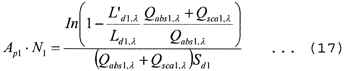
-

- Further, since Ap1 and Ap2 are obtained by giving radii rp1 and rp2 of the dust particles, N1 and N2 are acquired, and dust concentrations Cd1 and Cd2 are obtained from the following Expression (19) and Expression (20) corresponding to Expression (8). It is to be noted that, when the radii rp1 and rp2 of the dust particles are unknown or vary depending on situations, the accurate radii rp1 and rp2 of the dust particles cannot be given, and the accurate dust concentrations Cd1 and Cd2 cannot be obtained, but a measurement value of a temperature of an obj ect to be heated or a temperature of the dust which is a target in this method is not affected, and Ap1·N1 and Ap2·N2 can be considered to correspond to a load of the dust and can be exploited for control over the furnace or the like.
-

-

second radiance meters second radiance meters second radiance meter 40b. - Aside from the measurement of the radiances L'd1,λ and L'd2,λ of the dust by the
second radiance meters first radiance meter 20. Considering attenuation due to absorption and scattering of the dust in the first and second areas of dust presence and a radiance from the dust, the radiance L'c2,λ measured by thefirst radiance meter 20 is represented by the following Expression (21). A first term on the right side in the following Expression (21) represents a radiance L'c1,λ from the object to be heated after passing through the first dust area represented by the following Expression (22) while taking the attenuation due to absorption and scattering of the dust in the second area of dust presence into consideration. Furthermore, a second term on the right side in the following Expression (21) represents a radiance from the dust in the second area of dust presence while taking self-absorption and self-scattering due to the dust into consideration. Moreover, a first term on the right side in the following expression (22) represents a radiance from the object to be heated while taking the attenuation due to absorption and scattering of the dust in the first dust area into consideration, and a second term on the right side represents a radiance from the dust in the first area of dust presence while takin self-absorption and self-scattering due to the dust into consideration. -

first radiance meter 20 in the optical axis direction in the second area of dust presence. Furthermore, ap2,λ is an absorption coefficient of the dust in the second area of dust presence, and σp2,λ is a scattering coefficient of the dust in the second area of dust presence. -

first radiance meter 20 in the optical axis direction in the first area of dust presence. Further, ap1,λ is an absorption coefficient of the dust in the first area of dust presence, and σp1,λ is a scattering coefficient of the dust in the first area of dust presence. - Additionally, in Expressions (21) and (22), the radiances Ld1,λ and Ld2,λ of the dust and the radiance Lc,λ of the object to be heated are obtained from the dust temperatures Td1 and Td2 and the temperature Tc of the object to be heated on the bases of Planck's formula of Expression (2), and the absorption coefficients ap1,λ and ap2,λ and the scattering coefficients σp1,λ and σp2,λ of the dust are represented by Expression (3) and Expression (4), respectively.
- Here, the following Expression (23) represents an expression which obtains the radiance L'c1,λ from the object to be heated after passing through the first area of dust presence from the radiance L'c2,λ of the object to be heated 30 measured by the
first radiance meter 20 by substituting Expression (3) and Expression (4) in Expression (21).
- Further, Td2 is obtained from the radiance L'c2,λ of the object to be heated 30 measured at the wavelength λ1 or the wavelength λ2 by the
first radiance meter 20 and the radiances L'd2,λ1 and L'd2,λ2 of the dust measured by thesecond radiance meter 40b on the basis of Expression (16) and Expression (6), and L'c1,λ is obtained by substituting the radiance Ld2,λ of the dust at the wavelength λ1 or the wavelength λ2 used for the measurement of thefirst radiance meter 20 and Ap2·N2 obtained from Expression (18) in Expression (23). - Furthermore, the following Expression (24) represents an expression which obtains the radiance Lc,λ of the object to be heated 30 by substituting Expression (3) and Expression (4) in Expression (22) and modifying it. Td1 is obtained from the acquired L'c1,λ and the radiances L'd1,λ1 and L'd1,λ2 of the dust measured by the
second radiance meter 40a on the basis of Expression (15) and Expression (6), and the radiance Ld1,λ of the dust at the wavelength λ1 or the wavelength λ2 obtained from Expression (2) and used for the measurement of the first radiance meter 2 0 and Ap1·N1 obtained from Expression (17) are substituted, thereby acquiring the radiance Lc,λ of the object to be heated 30. It is to be noted that, as the wavelength at which the radiance L'c2,λ of the object to be heated 30 is measured, using either the wavelength λ1 or λ2 at the time of measuring the radiances L'd1,λ and L'd2,λ of the dust by thesecond radiance meters -

- Moreover, when the radiance Lc,λ of the object to be heated 30 is substituted in Expression (11), the temperature Tc of the object to be heated 30 can be obtained.
- It is to be noted that, at the time of measuring the radiance L'c2,λ of the object to be heated 30 by using the
first radiance meter 20, measuring the radiances L'c2,λ1 and L'c2,λ2 of the object to be heated 30 at two wavelengths, i.e., the wavelengths λ1 and λ2 in advance enables obtaining L'c1,λ1 and L'c1,λ2 from Expression (23), and further the following Expression (25) is derived from Expression (24). -

- Consequently, a radiance ratio (Lc,λ1/Lc,λ2) of the object to be heated 30 can be obtained from an emissivity ratio (εc,λ1/εc,λ2) of the object to be heated 30 without directly giving emissivities εc,λ1 and εc,λ2 of the object to be heated 3 0, and the temperature Tc of the object to be heated 3 0 can be acquired from Expression (6). In general, when the wavelengths λ1 and λ2 are close to each other, the emissivity ratio (εc,λ1/εc,λ2) can be considered as 1. Further, when the radiance L'c2,λ of object to be heated 30 is measured at two wavelengths in advance, the effect that a flame of the
burner 16 or radiation light emitted from the inner wall of thekiln hood 12 is reflected on the object to be heated 30 and enters thefirst radiance meter 20 can be suppressed, and an accuracy of the temperature measurement can be improved. Likewise, when the radiance L'c2,λ of the object to be heated 30 is measured at two wavelengths in advance, it is possible to suppress the effect of an error in the radiance Ld,λ or Ap·N of the dust calculated from a measurement value of thesecond radiance meter 40, which is caused when the radiation light emitted from theburner 16 or the inner wall of thekiln hood 12 is reflected on the wall surface in the furnace facing thesecond radiance meters first radiance meter 20, using λ1 and λ2 at the time of measuring the radiances L'd1,λ and L'd2,λ of the dust is simple and desirable, but combinations of other wavelengths, e.g., wavelengths λ1 and λ10, wavelengths λ9 ad λ2 as well as wavelengths λ9 and λ10 can suffice as long as the absorption coefficient ap,λ of the dust and the scattering coefficient σp,λ of the dust can be additionally obtained. In case of the wavelengths λ9 and λ10, Ld2,λ which is substituted in Expression (23) is calculated from Td2 at the wavelength λ9 and the wavelength λ10 and substituted on the basis of Expression (2), and the radiance Ld1,λ1 and Ld1,λ2 of the dust which are substituted in Expression (25) could be replaced with the radiances Ld1,λ9 and Ld1,λ10 obtained with the use of the wavelength λ9 and the wavelength λ10 from Td1 and substituted on the basis of Expression (2). - As described above, in the measuring method according to the second embodiment of the present invention, the temperature Tc of the clinker which is the object to be heated can be obtained in the furnace having the dust therein like a rotary kiln in the cement production equipment. In the measuring method according to the second embodiment of the present invention, even if a bias of a distribution of a dust temperature, dust concentration, a radius of each dust particle, or the like in the area of dust presence in the furnace is considerable in particular, a measurement accuracy can be improved. It is to be noted that the temperature Tc of the clinker, the dust temperatures Td1 and Td2, dust concentrations Cd1 and Cd2, and others may be manually calculated from the measured radiances L'c,λ, L'd1,λ, and L'd2,λ, but they may be automatically calculated by, e.g., calculating means such as a program of a
computer 21 connected to outputs of thefirst radiance meter 20 and thesecond radiance meters - Further, although the description has been given as to the example where a temperature of the object to be heated in the rotary kiln is measured in the first and second embodiments according to the present invention, the measuring method according to the present invention is not restricted to this example, and the temperature measuring method according to the present invention can be preferably used if it is an object in an atmosphere where dust is present. As examples other than the object to be heated, there are an object to be heated present in high-temperature furnaces (heating, smelting, refinement, firing, reactions, and others) other than a rotary kiln, a heat exchange tube in a boiler, and a solid or a liquid flowing through a duct as well as a heat transfer pipe or a partition wall in a heat exchanger. Furthermore, the object which is a temperature measurement target is not restricted to one having a high temperature above 1000°C like a clinker, and it may be one having approximately hundreds °C.
- Examples and comparative examples of the present invention will now be described in detail hereinafter.
- Assuming that λ1=0.9 µm, λ2=1.35 µm, a temperature Tc of an object to be heated=1450°C, an emissivity εc,λ of the object to be heated is 0.9 (λ1, λ2), a dust temperature Td=1000°C, dust concentration Cd=100g/m3 N (N means that a temperature of a dust-containing gas is 0°C and a pressure is an atmospheric pressure), a radius rp of a dust particle is 20 µm, an emissivity ξλ of the dust particle is 0.9 (λ1, λ2), a length sd of an area of dust presence when a radiance of the dust is measured by the
second radiance meter 40 is 5 m, a length sc of the area of dust presence when a radiance of the object to be heated 3 0 is measured by thefirst radiance meter 20 is 5 m, and density p of the dust particle is 3.18 g/cm3, when radiances L'c,λ1 and L'c,λ2 which are to be measured by thefirst radiance meter 20 are calculated at λ1 and λ2 from Expression (9), L'c,λ1=1. 94×109 and L'c,λ2=9. 02×109 are derived. - On the other hand, as shown in
FIG. 1 , cooling means 41 was provided, and asecond radiance meter 40 was installed at a positon facing a wall surface cooled to 300°C by the cooling means 41. It is to be noted that the cooling means 41 was installed as shown inFIG. 4 (b) by a method of providing a cylindrical concave portion which has an opening end in a wall surface and protrudes toward the outer side, and by winding a water cooled tube as the cooling means 41 on an outer periphery of the concave portion. Moreover, a cylinder length (a height) of the cylindrical concave portion was adjusted to provide a blackbody cavity, an emissivity of the wall surface was set to 0.999, and radiation light entered the blackbody cavity from a furnace inner wall surface of 1200°C surrounding this cavity. Additionally, L'd,λ1 and L'd,λ2 at the time of measuring at the two wavelengths λ1 and λ2 are acquired by thissecond radiance meter 40, Ld,λ1/Ld,λ2 which is a radiance ratio of the dust is calculated from Expression (5), and a dust temperature Td=1000°C is obtained from Expression (6). Further, Ap·N=0.2536 is obtained from Expression (7). - Then, these pieces of information are substituted in Expression (10) to obtain Lc,λ, and Tc=1451°C can be obtained from Expression (11). It is to be noted that this result is a result of measuring the radiance L'c,λ of the object to be heated by a method of measuring at one wavelength (λ=0.9 µm).
- Furthermore, these pieces of information are substituted in Expression (12) to obtain Lc,λ1/Lc,λ2, and Tc=1450°C can be obtained from Expression (6). It is to be noted that this result is a result of measuring the radiance L'c,λ of the object to be heated by a method of measuring at two wavelengths (λ=0.9 µm, and λ2=1.35 µm).
- On the other hand, in case of performing the measurement based on a two-color method which is an existing technology using no
second radiance meter 40, when a calculation is made on the basis of Expression (6) from a ratio of L'c,λ1=1. 94×109 and L'c,λ2=9. 02×109 which have been already obtained, Tc=1222°C is provided. That is, a deviation from 1450°C as the temperature of the object to be heated is 228°C when the existing technology which does not adopt thesecond radiance meter 40 is used, whereas it is 1°C when the method according to the present invention which measures the radiance L'c,λ of the object to be heated at one wavelength (λ=0.9 µm) is used, or it is 0°C when the method according to the present invention which measures the radiance L'c,λ of the object to be heated at two wavelengths (λ1=0.9 µm, and λ2=1.35 µm) is used, and it can be understood that a very high accuracy is achieved. - Further,
FIG. 6 shows transitions of measurement values provided by the existing technology which does not use thesecond radiance meter 40, the measuring method for measuring the radiance L'c,λ of the obj ect to be heated at one wavelength (λ=0.9 µm), and the method for measuring the radiance L'c,λ of the object to be heated at two wavelengths (λ1=0.9 µm, and λ2=1.35 µm) respectively, which are brought about by a change in the dust temperature Td when other conditions remain the same and Tc=1450 or 1250°C (the two-color method, this method, and this method (two colors) inFIG. 6 ). It can be understood that deviations become considerable as measurement values get closer to the dust temperature in the existing technology which is impractical, but accurate measurement values can be provided irrespective of the dust temperature in this method and this method (two colors). - Furthermore,
FIG. 7 shows transitions of measurement values provided by the existing technology which does not use thesecond radiance meter 40, the measuring method for measuring the radiance L'c,λ of the object to be heated at one wavelength (λ=0.9 µm), and the method for measuring the radiance L'c,λ of the object to be heated at two wavelengths (λ1=0.9 µm, and λ2=1.35 µm) respectively, which are brought about by a change in the dust concentration Cd when other conditions remain the same and Tc=1450 or 1250°C (the two-color method, this method, and this method (two colors) inFIG. 7 ). Although the existing technology is not affected when the dust concentration Cd is small, a deviation increases when measurement values get closer to 1000°C which is the dust temperature due to a rise of the dust concentration, and hence the existing technology is impractical, but the present method and the present method (two colors) are not greatly affected even though the dust concentration is high, and it can be understood that these methods have an accuracy far greater than that of the existing technology. - Moreover, Table 1 shows a measurement result of temperatures of the object to be heated when an emissivity of a wall surface facing the
second radiance meter 40 was changed when other conditions remained the same to see an effect of the emissivity of the wall surface. Here, in Table 1, anemissivity 0. 7 shows a case where the facing wall surface was made of a refractory and measurement was performed, and anemissivity 0. 9 shows a case where a blackbody coating was further applied to the wall surface made of the refractory and measurement was performed. It is to be noted that an emissivity 0.999 corresponds to a result of providing the blackbody cavity and performing measurement. Additionally, each numerical value in parentheses represents a deviation from 1450°C which is the temperature of the object to be heated. Further, a temperature of the wall surface facing thesecond radiance meter 40 was cooled to 300°C by the cooling means 41.[Table 1] Emissivity of facing wall surface 0.7 0.9 0.999 This method 1377 (-73) 1419 (-31) 1451 (+1) This method (two colors) 1480 (+30) 1459 (+9) 1450 (0) Two-color method (existing technology) 1222 (-228) 1222 (-228) 1222 (-228) - When the emissivity is 0.7, deviations in this method and this method (two colors) are as large as -73°C and 30°C respectively, but they are smaller than -228°C which is a deviation in the two-color method (the existing technology). Further, when the emissivity is 0.9, deviations in this method and this method (two colors) are -31°C and 9°C respectively, and hence the deviations can be reduced. Furthermore, as to each emissivity, it can be understood that the deviations of this method (two colors) are smaller than those of this method and the method for measuring the radiance L'c of the object to be heated at two wavelengths can greatly improve an accuracy.
- Assuming that λ1=0.9 µm, λ2=1.35 µm, a temperature Tc of an object to be heated is 1450°C, an emissivity εc,λ of the object to be heated is 0.9 (λ1, λ2), dust temperatures Td1=1000°C and Td2=900°C in the first and second areas of dust presence respectively, dust concentration Cd1=Cd2=100g/m3N, a radius rp1 of a dust particle=rp2=20 µm, an emissivity ξ1,λ of the dust particle is ξ2,λ=0.9 (λ1, λ2), a length sd1 of a first area of dust presence is 5 m and a length sd2 of a second area of dust presence is 5 m when a radiance of the dust is measured by the second radiance meters 40a and 40b, a length sc1 of the first area of dust presence is 3 m and a length sc2 of the area of the second area of dust presence is 2 m when a radiance of the object to be heated 30 is measured by the first radiance meter 20, and density ρ1 of the dust particles is ρ2=3.18 g/cm3, when radiances L'c2,λ1 and L'c2,λ2 which are to be measured by the first radiance meter 20 are calculated at λ1 and λ2 from Expression (21) and Expression (22), L'c2,λ1=1. 67×109 and L'c2,λ2=7 23×109 are derived.
- On the other hand, as shown in
FIG. 2 , cooling means 41a and 41b were provided, and thesecond radiance meters FIG 4(b) by a method of providing a cylindrical concave portion which has an opening end in a wall surface and protrudes toward the outer side, and by winding a water cooled tube as the cooling means 41a and 41b on an outer periphery of the concave portion. Moreover, the cylindrical concave portion was made to be a blackbody cavity by adjusting a cylinder length (a height), and an emissivity of the wall surface was set to 0.999. Additionally, L'd1,λ1, L'd1,λ2, L'd2,λ1, and L'd2,λ2 assuming the measurement at the two wavelengths λ1 and λ2 are acquired by the twosecond radiance meters - On the other hand, like this example, when lengths of the first and second areas of dust presence at the time of measuring the radiance of the object to be heated 30 by the
first radiance meter 20 are sc1=3 m and sc2=2 m respectively and the dust temperatures are Td1=1000°C and Td2=900°C respectively, in case of measuring the radiance of the dust only at one position in the area of dust presence and at an intermediate point in the area of dust presence by thesecond radiance meter 40 like Example 1, the length of the area of dust presence in Example 1 is sc=5 m (=sc1+sc2) and the dust temperature Td1 at the same point is 1000°C. As shown inFIG. 1 , the cooling means 41 was provided, and thesecond radiance meter 40 was installed at a positon facing a wall surface cooled to 300°C by the cooling means 41. It is to be noted that the cooling means 41 was installed as shown inFIG. 4 (b) by a method of providing a cylindrical concave portion which has an opening end in a wall surface and protrudes toward the outer side, and by winding a water cooled tube as the cooling means 41 on an outer periphery of the concave portion. Moreover, the cylindrical concave portion was made to be a blackbody by adjusting a cylinder length (a height), and an emissivity of the wall surface was set to 0.999. Additionally, L'd,λ1 and L'd,λ2 at the time of measuring at the two wavelengths λ1 and λ2 are acquired by thissecond radiance meter 40, Ld,λ1/Ld,λ2 which is a radiance ratio of the dust is obtained from Expression (5), the dust temperature Td=1000°C is calculated from Expression (6), and Ap·N=0.2536 is calculated from Expression (7). However, the radiances L'c,λ1 and L'c,λ measured by thefirst radiance meter 20 is L'c2,λ1=1.67×10⁹ and L'c2,λ2=7.23×10⁹ obtained on the earlier stage, and these values are substituted in Expression (10) to obtain Lc,λ, and Tc=1411°C is calculated from Expression (11). - When the measurement was performed by the two-color method as the existing technology which does not use the
second radiance meter 40, Tc=1254°C is derived from a ratio of L'c2,λ1=1.67×10⁹ and L'c2,λ2=7.23×10⁹ obtained on the earlier stage on the basis of a calculation using Expression (6). That is, deviations in the measurement performed at two positions in the area of dust presence and the measurement performed at one position in the same on the basis of this method and a deviation in the measurement on the basis of the existing technology (the two-color method) are 0°C, -39°C, and -196°C respectively, and it has been revealed that this method has a higher accuracy than that of the existing technology and that, if the dust temperature, the dust concentration, the radius of the dust particle, and others have distributions in the area of dust presence, increasing the number of positions at which the radiance of dust is measured enables enhancing a temperature measurement accuracy. - The present invention can be preferably used in measurement of a temperature of an object to be heated like a clinker having a high-temperature mainly in a furnace having dust therein like a rotary kiln in a cement production equipment.
-
- 10a
- cement production equipment
- 11
- rotary kiln
- 20
- first radiance meter
- 30
- object (object to be heated or the like)
- 40
- second radiance meter
Claims (7)
- A method for measuring a temperature of an object, the method using a first radiance meter which is provided to face the object in an atmosphere where dust is present and measures a radiance of the object and a second radiance meter which is provided without facing the object and measures a radiance of the dust present between the object and the first radiance meter so that a temperature of the object is measured from the radiance of the object measured by the first radiance meter and the radiance of the dust present between the object and the first radiance meter measured by the second radiance meter.
- The method for measuring a temperature of an object according to claim 1,
wherein the radiance of the dust is measured at two wavelengths. - The method for measuring a temperature of an object according to claim 1 or 2,
wherein, at the time of measuring the radiance of the dust, the measurement is performed in a state where a temperature of a wall surface facing the second radiance meter is lowered by cooling means. - The method for measuring a temperature of an object according to any one of claims 1 to 3,
wherein, at the time of measuring the radiance of the dust, an emissivity of the wall surface facing the second radiance meter is set to 0.9 or more. - The method for measuring a temperature of an object according to claim 4,
wherein, at the time of measuring a radiance of the dust, a blackbody cavity is provided in the wall surface facing the second radiance meter. - The method for measuring a temperature of an object according to any one of claims 1 to 5,
wherein the radiance of the object is measured at two wavelengths. - The method for measuring a temperature of an object according to any one of claims 1 to 6,
wherein a plurality of radiance meters are used as the second radiance meter to measure two or more radiances of the dust, and the measurement is made from the radiance of the object measured by the first radiance meter and the two or more radiances of the dust present between the object and the first radiance meter measured by the plurality of second radiance meters.
Applications Claiming Priority (2)
| Application Number | Priority Date | Filing Date | Title |
|---|---|---|---|
| JP2014053172A JP6438663B2 (en) | 2014-03-17 | 2014-03-17 | How to measure the temperature of an object in an atmosphere with dust |
| PCT/JP2015/055325 WO2015141412A1 (en) | 2014-03-17 | 2015-02-25 | Method for measuring temperature of object in atmosphere having dust |
Publications (3)
| Publication Number | Publication Date |
|---|---|
| EP3121572A1 true EP3121572A1 (en) | 2017-01-25 |
| EP3121572A4 EP3121572A4 (en) | 2017-12-27 |
| EP3121572B1 EP3121572B1 (en) | 2021-10-13 |
Family
ID=54144388
Family Applications (1)
| Application Number | Title | Priority Date | Filing Date |
|---|---|---|---|
| EP15764852.8A Active EP3121572B1 (en) | 2014-03-17 | 2015-02-25 | Method for measuring temperature of object in atmosphere having dust |
Country Status (8)
| Country | Link |
|---|---|
| US (1) | US9863812B2 (en) |
| EP (1) | EP3121572B1 (en) |
| JP (1) | JP6438663B2 (en) |
| KR (1) | KR102266823B1 (en) |
| CN (1) | CN106233106B (en) |
| AU (1) | AU2015232784B2 (en) |
| MY (1) | MY195082A (en) |
| WO (1) | WO2015141412A1 (en) |
Cited By (1)
| Publication number | Priority date | Publication date | Assignee | Title |
|---|---|---|---|---|
| EP3351913A4 (en) * | 2015-09-16 | 2019-02-27 | Mitsubishi Materials Corporation | METHOD FOR MEASURING TEMPERATURE OF AN OBJECT TO BE MEASURED, DUST TEMPERATURE AND DUST CONCENTRATION |
Families Citing this family (5)
| Publication number | Priority date | Publication date | Assignee | Title |
|---|---|---|---|---|
| MY191054A (en) * | 2015-09-16 | 2022-05-30 | Ube Industries | Method of measuring temperature of an object to be measured dust temperature and dust concentration |
| JP6728956B2 (en) * | 2016-05-13 | 2020-07-22 | 富士電機株式会社 | Particle measuring device |
| US10409275B2 (en) * | 2016-10-19 | 2019-09-10 | United Technologies Corporation | Oil debris monitoring (ODM) with adaptive learning |
| CN111272296B (en) * | 2020-02-19 | 2020-12-01 | 中南大学 | A correction method and system for reducing the influence of dust in the optical path on infrared temperature measurement |
| US12146794B2 (en) * | 2021-05-17 | 2024-11-19 | Rosemount Aerospace Inc. | Infrared inspection system for heaters comprised of positive temperature coefficient resistors |
Family Cites Families (16)
| Publication number | Priority date | Publication date | Assignee | Title |
|---|---|---|---|---|
| JPS525865B1 (en) * | 1969-04-25 | 1977-02-17 | ||
| JPS525865A (en) | 1975-07-03 | 1977-01-17 | Dainippon Printing Co Ltd | Method and device for producing hollow spherical article |
| GB1599949A (en) | 1977-04-04 | 1981-10-07 | Nippon Steel Corp | Method and an apparatus for simultaneous measurement of both temperature and emissivity of a heated material |
| JPS5485078A (en) | 1977-12-20 | 1979-07-06 | Nippon Steel Corp | Surface temperature measuring method of in-furnace objects |
| EP0083100B1 (en) | 1981-12-28 | 1988-04-06 | Nippon Steel Corporation | Method of measuring pipe temperature |
| CA1218866A (en) * | 1984-04-24 | 1987-03-10 | John M. Lucas | Tuyere pyrometer |
| JPH07174634A (en) | 1993-12-20 | 1995-07-14 | Nippon Steel Corp | Temperature measurement method for objects in the furnace |
| JP2000111398A (en) | 1998-09-30 | 2000-04-18 | Hamamatsu Photonics Kk | Measuring apparatus for self-luminescence from flame |
| JP2001249049A (en) | 2000-03-07 | 2001-09-14 | Mitsubishi Heavy Ind Ltd | Method for measuring temperature of molten slag |
| US7062187B2 (en) | 2002-10-31 | 2006-06-13 | Konica Minolta Holdings, Inc. | Fixing device for use in image forming apparatus |
| US7242803B2 (en) * | 2003-01-21 | 2007-07-10 | The United States Of America As Represented By The Secretary Of The Navy | System and method for significant dust detection and enhancement of dust images over land and ocean |
| US7379592B2 (en) * | 2003-01-21 | 2008-05-27 | United States Of America As Represented By The Secretary Of The Navy | System and method for significant dust detection and enhancement of dust images over land and ocean |
| JP2004252431A (en) | 2003-01-29 | 2004-09-09 | Konica Minolta Business Technologies Inc | Image forming apparatus and its fixing device |
| TWI481846B (en) * | 2007-11-15 | 2015-04-21 | Xtralis Technologies Ltd | Technique for measuring beam alignment in an active video smoke detection (AVSD) system |
| US9335219B2 (en) * | 2010-06-07 | 2016-05-10 | Exergen Corporation | Dual waveband temperature detector |
| JP2013210259A (en) * | 2012-03-30 | 2013-10-10 | Mitsubishi Materials Corp | Method for measuring temperatures of a heated object, powder dust and gas in furnace and emissivity thereof |
-
2014
- 2014-03-17 JP JP2014053172A patent/JP6438663B2/en active Active
-
2015
- 2015-02-25 EP EP15764852.8A patent/EP3121572B1/en active Active
- 2015-02-25 MY MYPI2016001686A patent/MY195082A/en unknown
- 2015-02-25 CN CN201580019724.3A patent/CN106233106B/en active Active
- 2015-02-25 US US15/124,475 patent/US9863812B2/en active Active
- 2015-02-25 KR KR1020167027551A patent/KR102266823B1/en active Active
- 2015-02-25 WO PCT/JP2015/055325 patent/WO2015141412A1/en not_active Ceased
- 2015-02-25 AU AU2015232784A patent/AU2015232784B2/en active Active
Cited By (1)
| Publication number | Priority date | Publication date | Assignee | Title |
|---|---|---|---|---|
| EP3351913A4 (en) * | 2015-09-16 | 2019-02-27 | Mitsubishi Materials Corporation | METHOD FOR MEASURING TEMPERATURE OF AN OBJECT TO BE MEASURED, DUST TEMPERATURE AND DUST CONCENTRATION |
Also Published As
| Publication number | Publication date |
|---|---|
| JP2015175756A (en) | 2015-10-05 |
| MY195082A (en) | 2023-01-09 |
| JP6438663B2 (en) | 2018-12-19 |
| KR20160135235A (en) | 2016-11-25 |
| US9863812B2 (en) | 2018-01-09 |
| AU2015232784A1 (en) | 2016-08-25 |
| US20170023411A1 (en) | 2017-01-26 |
| CN106233106B (en) | 2019-12-17 |
| EP3121572A4 (en) | 2017-12-27 |
| AU2015232784B2 (en) | 2019-07-11 |
| CN106233106A (en) | 2016-12-14 |
| WO2015141412A1 (en) | 2015-09-24 |
| KR102266823B1 (en) | 2021-06-17 |
| EP3121572B1 (en) | 2021-10-13 |
Similar Documents
| Publication | Publication Date | Title |
|---|---|---|
| EP3121572B1 (en) | Method for measuring temperature of object in atmosphere having dust | |
| Draper et al. | Two-dimensional flame temperature and emissivity measurements of pulverized oxy-coal flames | |
| Smart et al. | Characterisation of an oxy-coal flame through digital imaging | |
| WO2018076403A1 (en) | One-dimensional simulation method for predicting quality of clinker in rotary cement kiln | |
| US10852195B2 (en) | Method of measuring temperature of an object to be measured, dust temperature and dust concentration | |
| US20250198819A1 (en) | Method and device for measuring a flow velocity of a gas stream | |
| JP2013210259A (en) | Method for measuring temperatures of a heated object, powder dust and gas in furnace and emissivity thereof | |
| Schiemann et al. | Optical coal particle temperature measurement under oxy‐fuel conditions: measurement methodology and initial results | |
| Jiménez | Two-color, two-dimensional pyrometers based on monochrome and color cameras for high-temperature (> 1000 K) planar measurements | |
| US9551485B2 (en) | Method for controlling NOx concentration in exhaust gas in combustion facility using pulverized coal | |
| US5707444A (en) | Method for controlling the temperature in a kiln | |
| Hebel et al. | Experimental study of particle velocity fields and gas-phase temperatures in oxy-fuel biomass combustion in a semi-industrial swirl-stabilized combustion chamber | |
| Liu et al. | Integrated ef fective emissivity computation for non-isothermal non-axisymmetric cavities | |
| Kychakoff et al. | Use of acoustic temperature measurements in the cement manufacturing pyroprocess | |
| WO2017047376A1 (en) | Method of measuring temperature of an object to be measured, dust temperature and dust concentration | |
| YAMAMOTO et al. | DEVELOPMENT OF TECHNOLOGY FOR HIGH-ACCURACY TEMPERATURE MEASUREMENT OF CLINKER IN KILNS: PART2─ IMPROVEMENT OF MEASUREMENT ACCURACY FOR PRACTICAL APPLICATION | |
| JPH02306130A (en) | Method and apparatus for measuring kiln temperature | |
| KR100689153B1 (en) | Method for predicting slab temperature in a furnace. | |
| Schwotzer et al. | Experimental investigation of a concept for scale free reheating of semi-finished metal products | |
| Huang et al. | Experimental study on thermal environment and pollutant distribution during the cooling stage in a graphitization plant with an ultra-large surface pollution source | |
| Aleksandrov et al. | Improving the quality of alumina-containing sinter using water-cooled furnace shell | |
| Hayes et al. | Glass Furnaces |
Legal Events
| Date | Code | Title | Description |
|---|---|---|---|
| PUAI | Public reference made under article 153(3) epc to a published international application that has entered the european phase |
Free format text: ORIGINAL CODE: 0009012 |
|
| STAA | Information on the status of an ep patent application or granted ep patent |
Free format text: STATUS: REQUEST FOR EXAMINATION WAS MADE |
|
| 17P | Request for examination filed |
Effective date: 20160822 |
|
| AK | Designated contracting states |
Kind code of ref document: A1 Designated state(s): AL AT BE BG CH CY CZ DE DK EE ES FI FR GB GR HR HU IE IS IT LI LT LU LV MC MK MT NL NO PL PT RO RS SE SI SK SM TR |
|
| AX | Request for extension of the european patent |
Extension state: BA ME |
|
| DAX | Request for extension of the european patent (deleted) | ||
| A4 | Supplementary search report drawn up and despatched |
Effective date: 20171127 |
|
| RIC1 | Information provided on ipc code assigned before grant |
Ipc: F27D 7/06 20060101ALI20171117BHEP Ipc: G01J 5/06 20060101ALI20171117BHEP Ipc: F27D 19/00 20060101ALI20171117BHEP Ipc: F27D 21/00 20060101ALI20171117BHEP Ipc: G01J 5/60 20060101ALI20171117BHEP Ipc: F27B 7/20 20060101ALI20171117BHEP Ipc: G01J 5/00 20060101AFI20171117BHEP Ipc: F27B 7/42 20060101ALI20171117BHEP |
|
| RAP1 | Party data changed (applicant data changed or rights of an application transferred) |
Owner name: MITSUBISHI MATERIALS CORPORATION |
|
| GRAP | Despatch of communication of intention to grant a patent |
Free format text: ORIGINAL CODE: EPIDOSNIGR1 |
|
| STAA | Information on the status of an ep patent application or granted ep patent |
Free format text: STATUS: GRANT OF PATENT IS INTENDED |
|
| INTG | Intention to grant announced |
Effective date: 20210629 |
|
| GRAS | Grant fee paid |
Free format text: ORIGINAL CODE: EPIDOSNIGR3 |
|
| GRAA | (expected) grant |
Free format text: ORIGINAL CODE: 0009210 |
|
| STAA | Information on the status of an ep patent application or granted ep patent |
Free format text: STATUS: THE PATENT HAS BEEN GRANTED |
|
| AK | Designated contracting states |
Kind code of ref document: B1 Designated state(s): AL AT BE BG CH CY CZ DE DK EE ES FI FR GB GR HR HU IE IS IT LI LT LU LV MC MK MT NL NO PL PT RO RS SE SI SK SM TR |
|
| REG | Reference to a national code |
Ref country code: GB Ref legal event code: FG4D |
|
| REG | Reference to a national code |
Ref country code: CH Ref legal event code: EP |
|
| REG | Reference to a national code |
Ref country code: DE Ref legal event code: R096 Ref document number: 602015074106 Country of ref document: DE |
|
| REG | Reference to a national code |
Ref country code: IE Ref legal event code: FG4D |
|
| REG | Reference to a national code |
Ref country code: AT Ref legal event code: REF Ref document number: 1438505 Country of ref document: AT Kind code of ref document: T Effective date: 20211115 |
|
| REG | Reference to a national code |
Ref country code: LT Ref legal event code: MG9D |
|
| REG | Reference to a national code |
Ref country code: NL Ref legal event code: MP Effective date: 20211013 |
|
| REG | Reference to a national code |
Ref country code: AT Ref legal event code: MK05 Ref document number: 1438505 Country of ref document: AT Kind code of ref document: T Effective date: 20211013 |
|
| PG25 | Lapsed in a contracting state [announced via postgrant information from national office to epo] |
Ref country code: RS Free format text: LAPSE BECAUSE OF FAILURE TO SUBMIT A TRANSLATION OF THE DESCRIPTION OR TO PAY THE FEE WITHIN THE PRESCRIBED TIME-LIMIT Effective date: 20211013 Ref country code: LT Free format text: LAPSE BECAUSE OF FAILURE TO SUBMIT A TRANSLATION OF THE DESCRIPTION OR TO PAY THE FEE WITHIN THE PRESCRIBED TIME-LIMIT Effective date: 20211013 Ref country code: FI Free format text: LAPSE BECAUSE OF FAILURE TO SUBMIT A TRANSLATION OF THE DESCRIPTION OR TO PAY THE FEE WITHIN THE PRESCRIBED TIME-LIMIT Effective date: 20211013 Ref country code: BG Free format text: LAPSE BECAUSE OF FAILURE TO SUBMIT A TRANSLATION OF THE DESCRIPTION OR TO PAY THE FEE WITHIN THE PRESCRIBED TIME-LIMIT Effective date: 20220113 Ref country code: AT Free format text: LAPSE BECAUSE OF FAILURE TO SUBMIT A TRANSLATION OF THE DESCRIPTION OR TO PAY THE FEE WITHIN THE PRESCRIBED TIME-LIMIT Effective date: 20211013 |
|
| PG25 | Lapsed in a contracting state [announced via postgrant information from national office to epo] |
Ref country code: IS Free format text: LAPSE BECAUSE OF FAILURE TO SUBMIT A TRANSLATION OF THE DESCRIPTION OR TO PAY THE FEE WITHIN THE PRESCRIBED TIME-LIMIT Effective date: 20220213 Ref country code: SE Free format text: LAPSE BECAUSE OF FAILURE TO SUBMIT A TRANSLATION OF THE DESCRIPTION OR TO PAY THE FEE WITHIN THE PRESCRIBED TIME-LIMIT Effective date: 20211013 Ref country code: PT Free format text: LAPSE BECAUSE OF FAILURE TO SUBMIT A TRANSLATION OF THE DESCRIPTION OR TO PAY THE FEE WITHIN THE PRESCRIBED TIME-LIMIT Effective date: 20220214 Ref country code: PL Free format text: LAPSE BECAUSE OF FAILURE TO SUBMIT A TRANSLATION OF THE DESCRIPTION OR TO PAY THE FEE WITHIN THE PRESCRIBED TIME-LIMIT Effective date: 20211013 Ref country code: NO Free format text: LAPSE BECAUSE OF FAILURE TO SUBMIT A TRANSLATION OF THE DESCRIPTION OR TO PAY THE FEE WITHIN THE PRESCRIBED TIME-LIMIT Effective date: 20220113 Ref country code: NL Free format text: LAPSE BECAUSE OF FAILURE TO SUBMIT A TRANSLATION OF THE DESCRIPTION OR TO PAY THE FEE WITHIN THE PRESCRIBED TIME-LIMIT Effective date: 20211013 Ref country code: LV Free format text: LAPSE BECAUSE OF FAILURE TO SUBMIT A TRANSLATION OF THE DESCRIPTION OR TO PAY THE FEE WITHIN THE PRESCRIBED TIME-LIMIT Effective date: 20211013 Ref country code: HR Free format text: LAPSE BECAUSE OF FAILURE TO SUBMIT A TRANSLATION OF THE DESCRIPTION OR TO PAY THE FEE WITHIN THE PRESCRIBED TIME-LIMIT Effective date: 20211013 Ref country code: GR Free format text: LAPSE BECAUSE OF FAILURE TO SUBMIT A TRANSLATION OF THE DESCRIPTION OR TO PAY THE FEE WITHIN THE PRESCRIBED TIME-LIMIT Effective date: 20220114 Ref country code: ES Free format text: LAPSE BECAUSE OF FAILURE TO SUBMIT A TRANSLATION OF THE DESCRIPTION OR TO PAY THE FEE WITHIN THE PRESCRIBED TIME-LIMIT Effective date: 20211013 |
|
| REG | Reference to a national code |
Ref country code: DE Ref legal event code: R097 Ref document number: 602015074106 Country of ref document: DE |
|
| PG25 | Lapsed in a contracting state [announced via postgrant information from national office to epo] |
Ref country code: SM Free format text: LAPSE BECAUSE OF FAILURE TO SUBMIT A TRANSLATION OF THE DESCRIPTION OR TO PAY THE FEE WITHIN THE PRESCRIBED TIME-LIMIT Effective date: 20211013 Ref country code: SK Free format text: LAPSE BECAUSE OF FAILURE TO SUBMIT A TRANSLATION OF THE DESCRIPTION OR TO PAY THE FEE WITHIN THE PRESCRIBED TIME-LIMIT Effective date: 20211013 Ref country code: RO Free format text: LAPSE BECAUSE OF FAILURE TO SUBMIT A TRANSLATION OF THE DESCRIPTION OR TO PAY THE FEE WITHIN THE PRESCRIBED TIME-LIMIT Effective date: 20211013 Ref country code: EE Free format text: LAPSE BECAUSE OF FAILURE TO SUBMIT A TRANSLATION OF THE DESCRIPTION OR TO PAY THE FEE WITHIN THE PRESCRIBED TIME-LIMIT Effective date: 20211013 Ref country code: DK Free format text: LAPSE BECAUSE OF FAILURE TO SUBMIT A TRANSLATION OF THE DESCRIPTION OR TO PAY THE FEE WITHIN THE PRESCRIBED TIME-LIMIT Effective date: 20211013 Ref country code: CZ Free format text: LAPSE BECAUSE OF FAILURE TO SUBMIT A TRANSLATION OF THE DESCRIPTION OR TO PAY THE FEE WITHIN THE PRESCRIBED TIME-LIMIT Effective date: 20211013 |
|
| PLBE | No opposition filed within time limit |
Free format text: ORIGINAL CODE: 0009261 |
|
| STAA | Information on the status of an ep patent application or granted ep patent |
Free format text: STATUS: NO OPPOSITION FILED WITHIN TIME LIMIT |
|
| REG | Reference to a national code |
Ref country code: DE Ref legal event code: R081 Ref document number: 602015074106 Country of ref document: DE Owner name: MITSUBISHI UBE CEMENT CORP., JP Free format text: FORMER OWNER: MITSUBISHI MATERIALS CORP., TOKYO, JP |
|
| 26N | No opposition filed |
Effective date: 20220714 |
|
| PG25 | Lapsed in a contracting state [announced via postgrant information from national office to epo] |
Ref country code: MC Free format text: LAPSE BECAUSE OF FAILURE TO SUBMIT A TRANSLATION OF THE DESCRIPTION OR TO PAY THE FEE WITHIN THE PRESCRIBED TIME-LIMIT Effective date: 20211013 |
|
| REG | Reference to a national code |
Ref country code: CH Ref legal event code: PL |
|
| REG | Reference to a national code |
Ref country code: BE Ref legal event code: MM Effective date: 20220228 |
|
| PG25 | Lapsed in a contracting state [announced via postgrant information from national office to epo] |
Ref country code: LU Free format text: LAPSE BECAUSE OF NON-PAYMENT OF DUE FEES Effective date: 20220225 Ref country code: AL Free format text: LAPSE BECAUSE OF FAILURE TO SUBMIT A TRANSLATION OF THE DESCRIPTION OR TO PAY THE FEE WITHIN THE PRESCRIBED TIME-LIMIT Effective date: 20211013 |
|
| REG | Reference to a national code |
Ref country code: GB Ref legal event code: 732E Free format text: REGISTERED BETWEEN 20221027 AND 20221102 |
|
| PG25 | Lapsed in a contracting state [announced via postgrant information from national office to epo] |
Ref country code: SI Free format text: LAPSE BECAUSE OF FAILURE TO SUBMIT A TRANSLATION OF THE DESCRIPTION OR TO PAY THE FEE WITHIN THE PRESCRIBED TIME-LIMIT Effective date: 20211013 |
|
| PG25 | Lapsed in a contracting state [announced via postgrant information from national office to epo] |
Ref country code: LI Free format text: LAPSE BECAUSE OF NON-PAYMENT OF DUE FEES Effective date: 20220228 Ref country code: IE Free format text: LAPSE BECAUSE OF NON-PAYMENT OF DUE FEES Effective date: 20220225 Ref country code: CH Free format text: LAPSE BECAUSE OF NON-PAYMENT OF DUE FEES Effective date: 20220228 |
|
| PG25 | Lapsed in a contracting state [announced via postgrant information from national office to epo] |
Ref country code: BE Free format text: LAPSE BECAUSE OF NON-PAYMENT OF DUE FEES Effective date: 20220228 |
|
| PG25 | Lapsed in a contracting state [announced via postgrant information from national office to epo] |
Ref country code: HU Free format text: LAPSE BECAUSE OF FAILURE TO SUBMIT A TRANSLATION OF THE DESCRIPTION OR TO PAY THE FEE WITHIN THE PRESCRIBED TIME-LIMIT; INVALID AB INITIO Effective date: 20150225 |
|
| PG25 | Lapsed in a contracting state [announced via postgrant information from national office to epo] |
Ref country code: MK Free format text: LAPSE BECAUSE OF FAILURE TO SUBMIT A TRANSLATION OF THE DESCRIPTION OR TO PAY THE FEE WITHIN THE PRESCRIBED TIME-LIMIT Effective date: 20211013 Ref country code: CY Free format text: LAPSE BECAUSE OF FAILURE TO SUBMIT A TRANSLATION OF THE DESCRIPTION OR TO PAY THE FEE WITHIN THE PRESCRIBED TIME-LIMIT Effective date: 20211013 |
|
| PG25 | Lapsed in a contracting state [announced via postgrant information from national office to epo] |
Ref country code: MT Free format text: LAPSE BECAUSE OF FAILURE TO SUBMIT A TRANSLATION OF THE DESCRIPTION OR TO PAY THE FEE WITHIN THE PRESCRIBED TIME-LIMIT Effective date: 20211013 |
|
| PG25 | Lapsed in a contracting state [announced via postgrant information from national office to epo] |
Ref country code: TR Free format text: LAPSE BECAUSE OF FAILURE TO SUBMIT A TRANSLATION OF THE DESCRIPTION OR TO PAY THE FEE WITHIN THE PRESCRIBED TIME-LIMIT Effective date: 20211013 |
|
| PGFP | Annual fee paid to national office [announced via postgrant information from national office to epo] |
Ref country code: FR Payment date: 20251231 Year of fee payment: 12 |
|
| PGFP | Annual fee paid to national office [announced via postgrant information from national office to epo] |
Ref country code: GB Payment date: 20260106 Year of fee payment: 12 |
|
| PGFP | Annual fee paid to national office [announced via postgrant information from national office to epo] |
Ref country code: DE Payment date: 20260102 Year of fee payment: 12 |
|
| PGFP | Annual fee paid to national office [announced via postgrant information from national office to epo] |
Ref country code: IT Payment date: 20260122 Year of fee payment: 12 |