EP3121540A1 - Refrigeration system including evaporators associated in parallel - Google Patents
Refrigeration system including evaporators associated in parallel Download PDFInfo
- Publication number
- EP3121540A1 EP3121540A1 EP16179277.5A EP16179277A EP3121540A1 EP 3121540 A1 EP3121540 A1 EP 3121540A1 EP 16179277 A EP16179277 A EP 16179277A EP 3121540 A1 EP3121540 A1 EP 3121540A1
- Authority
- EP
- European Patent Office
- Prior art keywords
- evaporators
- evaporator
- parallel
- outflow
- refrigeration system
- Prior art date
- Legal status (The legal status is an assumption and is not a legal conclusion. Google has not performed a legal analysis and makes no representation as to the accuracy of the status listed.)
- Withdrawn
Links
- 238000005057 refrigeration Methods 0.000 title claims abstract description 36
- 239000007788 liquid Substances 0.000 claims abstract description 38
- 239000012530 fluid Substances 0.000 claims description 10
- 230000006835 compression Effects 0.000 claims description 4
- 238000007906 compression Methods 0.000 claims description 4
- 230000000694 effects Effects 0.000 claims description 3
- 238000005461 lubrication Methods 0.000 claims description 2
- 238000001704 evaporation Methods 0.000 description 12
- 230000008020 evaporation Effects 0.000 description 12
- 239000003507 refrigerant Substances 0.000 description 10
- 238000001816 cooling Methods 0.000 description 4
- 238000007710 freezing Methods 0.000 description 3
- 230000008014 freezing Effects 0.000 description 3
- 229920006395 saturated elastomer Polymers 0.000 description 3
- 239000004610 Internal Lubricant Substances 0.000 description 1
- 239000003990 capacitor Substances 0.000 description 1
- 238000010276 construction Methods 0.000 description 1
- 239000002826 coolant Substances 0.000 description 1
- 230000009977 dual effect Effects 0.000 description 1
- 238000009413 insulation Methods 0.000 description 1
- 238000002955 isolation Methods 0.000 description 1
- 239000007791 liquid phase Substances 0.000 description 1
- 239000000314 lubricant Substances 0.000 description 1
- 239000002184 metal Substances 0.000 description 1
- 230000037361 pathway Effects 0.000 description 1
Images

Classifications
-
- F—MECHANICAL ENGINEERING; LIGHTING; HEATING; WEAPONS; BLASTING
- F25—REFRIGERATION OR COOLING; COMBINED HEATING AND REFRIGERATION SYSTEMS; HEAT PUMP SYSTEMS; MANUFACTURE OR STORAGE OF ICE; LIQUEFACTION SOLIDIFICATION OF GASES
- F25B—REFRIGERATION MACHINES, PLANTS OR SYSTEMS; COMBINED HEATING AND REFRIGERATION SYSTEMS; HEAT PUMP SYSTEMS
- F25B5/00—Compression machines, plants or systems, with several evaporator circuits, e.g. for varying refrigerating capacity
- F25B5/02—Compression machines, plants or systems, with several evaporator circuits, e.g. for varying refrigerating capacity arranged in parallel
-
- F—MECHANICAL ENGINEERING; LIGHTING; HEATING; WEAPONS; BLASTING
- F25—REFRIGERATION OR COOLING; COMBINED HEATING AND REFRIGERATION SYSTEMS; HEAT PUMP SYSTEMS; MANUFACTURE OR STORAGE OF ICE; LIQUEFACTION SOLIDIFICATION OF GASES
- F25B—REFRIGERATION MACHINES, PLANTS OR SYSTEMS; COMBINED HEATING AND REFRIGERATION SYSTEMS; HEAT PUMP SYSTEMS
- F25B31/00—Compressor arrangements
- F25B31/002—Lubrication
-
- F—MECHANICAL ENGINEERING; LIGHTING; HEATING; WEAPONS; BLASTING
- F25—REFRIGERATION OR COOLING; COMBINED HEATING AND REFRIGERATION SYSTEMS; HEAT PUMP SYSTEMS; MANUFACTURE OR STORAGE OF ICE; LIQUEFACTION SOLIDIFICATION OF GASES
- F25D—REFRIGERATORS; COLD ROOMS; ICE-BOXES; COOLING OR FREEZING APPARATUS NOT OTHERWISE PROVIDED FOR
- F25D11/00—Self-contained movable devices, e.g. domestic refrigerators
- F25D11/02—Self-contained movable devices, e.g. domestic refrigerators with cooling compartments at different temperatures
- F25D11/022—Self-contained movable devices, e.g. domestic refrigerators with cooling compartments at different temperatures with two or more evaporators
-
- F—MECHANICAL ENGINEERING; LIGHTING; HEATING; WEAPONS; BLASTING
- F25—REFRIGERATION OR COOLING; COMBINED HEATING AND REFRIGERATION SYSTEMS; HEAT PUMP SYSTEMS; MANUFACTURE OR STORAGE OF ICE; LIQUEFACTION SOLIDIFICATION OF GASES
- F25B—REFRIGERATION MACHINES, PLANTS OR SYSTEMS; COMBINED HEATING AND REFRIGERATION SYSTEMS; HEAT PUMP SYSTEMS
- F25B2500/00—Problems to be solved
- F25B2500/01—Geometry problems, e.g. for reducing size
-
- F—MECHANICAL ENGINEERING; LIGHTING; HEATING; WEAPONS; BLASTING
- F25—REFRIGERATION OR COOLING; COMBINED HEATING AND REFRIGERATION SYSTEMS; HEAT PUMP SYSTEMS; MANUFACTURE OR STORAGE OF ICE; LIQUEFACTION SOLIDIFICATION OF GASES
- F25B—REFRIGERATION MACHINES, PLANTS OR SYSTEMS; COMBINED HEATING AND REFRIGERATION SYSTEMS; HEAT PUMP SYSTEMS
- F25B2600/00—Control issues
- F25B2600/25—Control of valves
- F25B2600/2511—Evaporator distribution valves
Definitions
- the invention relates to a refrigeration system including at least two evaporators connected in parallel, and more particularly, two evaporators even associated in series, has its outflows tied to the input path of an accumulator device liquids, which comprises one outflow capable of being fluidly connected to the suction path of a compressor.
- the current state of the art comprises a plurality of arrangements and constructions of refrigeration systems and, in particular, refrigeration systems including at least two evaporators.
- this refrigeration system category - with at least two evaporators - is due to the fact that the vast majority of refrigeration appliances, the conventional refrigerator comprises at least two refrigerated compartments operating in different temperature ranges such as, for example, refrigerators comprise a freezing chamber and a cooling chamber.
- this type of arrangement (two evaporators operating at different pressure and temperature ranges, associated in parallel) can be achieved through the use of a single compressor.
- US2123497 and US3108453 documents illustrate rudimentary buildings of refrigeration systems that use a single compressor including at least two evaporators connected in parallel capable of operating in different pressure and temperature ranges.
- this type of arrangement (two evaporators operating at different pressure and temperature ranges, associated in parallel) can be achieved through the use of a single com-pressor, provided that there are means for selecting only one of the two (or multiple) evaporators and means for connecting the outflow of the two (or multiples) evaporators through the single suction of said compressor.
- the outflow of the low evaporation temperature evaporator further comprises, in a previous section for connection to the outflow of the average evaporation temperature of the evaporator (cooler), a device liquid accumulator associated in series with a one-way check valve.
- the series of the two components prevents the refrigerant fluid flows from the average evaporation temperature of the evaporator (higher pressure) to the evaporator very low lower evaporation temperature (smaller pressure).
- a refrigeration system comprising at least two evaporators connected in parallel wherein said evaporators operate essentially independent manner, i.e. without the normal or atypical conditions of operation an evaporator influence the operation of another evaporator.
- the cooling system including at least two evaporators associated parallel disclosed herein is especially dedicated to the use of fluid compressor capable of operating without the use of internal lubricants as is the case, for example, certain types of compressors.
- a refrigeration system including at least two associated evaporators in parallel wherein said evaporators connected in parallel operate in different pressure and temperature ranges; said refrigeration system comprising at least two evaporators connected in parallel, further comprising: at least one compressor, at least one condenser, at least one switch device, at least a first expansion device, at least a second expansion device, and at least one liquid accumulator; the outflow of the compressor being fluidly connected to the inlet path from the condenser; the condenser outflow being fluidly connected to the switching device via inlet; the outflow of commutation device being fluidly connected to the first expansion device; the outflow via the switching device is fluidly connected to the second expansion device; said liquid accumulator comprising at least one via lower inlet immersed in the liquid, at least one upper inlet path, and at least one upper outflow; said refrigeration system comprising at least two evaporators connected in parallel with special and preferentially characterized in that it further comprises: at least one dry expansion
- said liquid accumulator is preferably at a higher gravitational potential relative to the flooded evaporator so as to define a siphon effect between said liquid accumulator and said flooded evaporator.
- the moving parts of the compressor compression mechanism does not use oil - that is, preferably operating without lubrication liquids.
- the moving parts of the compressor compression mechanism may cooperate with oil and at least one oil separator.
- said liquid accumulator may comprise at least one additional special compartment evaporator of a refrigeration system.
- the evaporators can be classified according to their form of "power", that is, the evaporators can be defined as dry expansion evaporators, flooded evaporators or liquid over-feeding evaporators.
- the dry expansion evaporators are often "fed” by fluid previously turbulent refrigerant (liquid and vapor), and in its outflow, all the refrigerant is in the form of superheated steam.
- Flooded evaporators usually are "fed” by only the refrigerant in liquid form, it being at its output, all the refrigerant is in the form of dry saturated vapor fluid.
- the refrigeration system including at least two evaporators associated in parallel is primarily composed of a compressor 1, a condenser 2, a switching device 3 a first expansion device 41, one second expansion device 42, a dry expansion evaporator 51, a evaporates pain flooded 52 and a liquid accumulator 6.
- the compressor 1 is a compressor fundamentally conventional comprising a single outflow 11 and a single suction path 12.
- the condenser 2 it is essentially a capacitor conventional comprising an inlet path 21 and an outflow 22.
- the switching device 3 is any device, comprising an inlet path 31 and at least two outflows 32 and 33, is able to switch the fluid communication of its inlet path 31 with only one of the at least two outflows 32 or 33.
- said switching device 3 it is fundamentally a conventionally three-way valve for two positions.
- Both the first expansion device 41 as the second expansion device 42 these are traditional expansion devices, and preferentially, conventional capillary tubes widely known to those skilled in the technical subject.
- the dry expansion evaporator 51 which is used as evaporator of a cooling chamber (not shown), or used as high pressure and low temperature evaporator, it is a traditional dry expansion evaporator fundamentally comprising an inlet path 511 and an outflow 512.
- the flooded evaporator 52 which is used as an evaporator of a freezing chamber (not shown), this is, used as low pressure and very low temperature evaporator, it is flooded evaporator conventional, comprising an inlet path 521 and outflow 522.
- the liquid accumulator 6 in turn, also is a liquid accumulator conventionally used in refrigeration systems, and comprises an airtight casing provided with at least one inlet through the bottom 61, by least one upper inlet path 62 and at least one superior outflow 63.
- the outflow 11 to the compressor 1 is fluidly connected to the inlet path 21 to the condenser 2.
- the outflow 22 of the condenser 2 is fluidly connected to the inlet 31 of the switching device 3.
- the outflow 32 of the switching device 3 is fluidly connected to the first expansion device 41, which is connected to the inlet path 511 to the dry expansion evaporator 51.
- the outflow 512 of said dry expansion evaporator 51 is fluidly connected to the upper inlet path 62 of the liquid accumulator 6.
- the outflow 33 of the switching device3 is fluidly connected to the second expansion device 42, which is connected to the input 521 via the flooded evaporator 52.
- the outflow 522 of the aforementioned flooded evaporator 52 is fluidly connected to a bottom inlet path 61 of the liquid accumulator 6.
- the liquid accumulator 6 ultimately perform two simultaneous functions, including: i) means of connection between the outflows 512 and 522 of evaporators 51 and 52 with the suction path 12 of the compressor 1; and II) means of insulation between the evaporation line of the dry expansion evaporator 51 and the evaporation line of the flooded evaporator 52.
- the liquid tank 6 acts as a medium of isolation between rows of evaporation, it can be said that it is the major responsible for maintaining the independence between the evaporation lines and, in particular, maintaining the 52 always flooded evaporator flooded condition, even being the same not operating (depending on the operation of dry expansion evaporator 51).
- the compressor 1 tends to suck only steam superheated derived from said dry expansion evaporator 51, and the flooded evaporator 52 is still flooded with coolant in which the liquid in the tank should be at its lowest level and the lower inlet always flooded.
- compressor 1 tends to suck, at first, both superheated steam arising from said dry expansion evaporator 51 as dry saturated steam coming from the flooded evaporator 52, and, in a second time, only dry saturated steam coming from the flooded evaporator 52, and the refrigerant contained in dry expansion evaporator 51 is completely drained and deposited in the accumulator at its maximum while maintaining the outflow to the compressor always with overheated steam.
- the liquid accumulator 6 has to be in a greater gravitational potential relative to the flooded evaporator 52, after all, the greatest potential gravitational ends to define a siphon effect between said liquid accumulator 6 and the aforementioned flooded evaporator 52, preventing refrigerant liquid to change position when not suctioned.
- the refrigeration system including at least two evaporators connected in parallel herein disclosed is also totally capable of operating independently of the greater gravitational potential of the liquid accumulator 6 in relation to the flooded evaporator 52, after all, pressure difference between the evaporators 51 and 52, depending on the dynamics of established refrigeration, i.e., the pressure of said dry expansion evaporator 51 being greater than the pressure of the flooded evaporator 52 (depending on specific dimensioning of the expansion devices 41 and 42, of course) is sufficient to maintain the refrigerant in liquid phase only liquid in the lower region of the accumulator 6, and consequently throughout the flooded evaporator 52.
- the compressor 1 is about a compressor mainly conventionally capable to operate free of lubricants.
- figure 3 and certain nomenclatures above used, are intended to illustrate the preferred embodiment of the invention in question, cannot be interpreted as limiting embodiment, after all, the scope of the invention in question must be considered as wide as the interpretation of the claims, further including the possible equivalent means.
Landscapes
- Engineering & Computer Science (AREA)
- Physics & Mathematics (AREA)
- Mechanical Engineering (AREA)
- Thermal Sciences (AREA)
- General Engineering & Computer Science (AREA)
- Chemical & Material Sciences (AREA)
- Combustion & Propulsion (AREA)
- Devices That Are Associated With Refrigeration Equipment (AREA)
- Analytical Chemistry (AREA)
- Power Engineering (AREA)
Abstract
Description
- The invention relates to a refrigeration system including at least two evaporators connected in parallel, and more particularly, two evaporators even associated in series, has its outflows tied to the input path of an accumulator device liquids, which comprises one outflow capable of being fluidly connected to the suction path of a compressor.
- As is known to the skilled technicians in the subject, the current state of the art comprises a plurality of arrangements and constructions of refrigeration systems and, in particular, refrigeration systems including at least two evaporators. Of course, this refrigeration system category - with at least two evaporators - is due to the fact that the vast majority of refrigeration appliances, the conventional refrigerator comprises at least two refrigerated compartments operating in different temperature ranges such as, for example, refrigerators comprise a freezing chamber and a cooling chamber.
- Given this premise, it is highlighted that the refrigeration systems which at least two evaporators operate at different pressure ranges and temperature, which are connected in parallel.
- According to the current state of the art, this type of arrangement (two evaporators operating at different pressure and temperature ranges, associated in parallel) can be achieved through the use of a single compressor.
-
- Also in accordance with the current state of the art, this type of arrangement (two evaporators operating at different pressure and temperature ranges, associated in parallel) can be achieved through the use of a single com-pressor, provided that there are means for selecting only one of the two (or multiple) evaporators and means for connecting the outflow of the two (or multiples) evaporators through the single suction of said compressor.
- In this scenario, there is the
EP1087186 document, which describes and illustrates a dual evaporator refrigeration system as schematically illustrated infigure 2 , comprises two evaporators operating at different temperature and pressure ranges associated in parallel. Therefore, it is pre-seen a low temperature evaporator (cooling chamber evaporator), and a very low temperature evaporator (freezing chamber evaporator). The selection of one among these two evaporators is usually performed by means of valve arranged between the outlet of the condenser and input pathways for each of the expansion devices evaporators. As the compressor has only one suction means, the outflows of the two evaporators are connected together and to the suction path of the compressor. - However, it remains to emphasize that the outflow of the low evaporation temperature evaporator (freezer) further comprises, in a previous section for connection to the outflow of the average evaporation temperature of the evaporator (cooler), a device liquid accumulator associated in series with a one-way check valve. The series of the two components prevents the refrigerant fluid flows from the average evaporation temperature of the evaporator (higher pressure) to the evaporator very low lower evaporation temperature (smaller pressure).
- While this refrigeration system is, in theory, efficient, it is noted that the same has a drawback related to the operation period in which part of the refrigerant fluid is pumped from the evaporation low temperature evaporator (freezer) to the evaporator average evaporation temperature (refrigerator), after all, all of said refrigerant tends to migrate from the average evaporation temperature of the evaporator to the evaporator low evaporation temperature during operation of the system. At the most, there is even any failure of unidirectional check valve result in compromising total system efficiency.
- Based on this scenario that arises the invention in question.
- It is therefore the primary objective of the subject invention disclose a refrigeration system comprising at least two evaporators connected in parallel wherein said evaporators operate essentially independent manner, i.e. without the normal or atypical conditions of operation an evaporator influence the operation of another evaporator.
- Additionally, one of the goals of the subject invention that the cooling system including at least two evaporators associated parallel disclosed herein is especially dedicated to the use of fluid compressor capable of operating without the use of internal lubricants as is the case, for example, certain types of compressors.
- The aforementioned aims are fully achieved by a refrigeration system including at least two associated evaporators in parallel wherein said evaporators connected in parallel operate in different pressure and temperature ranges; said refrigeration system comprising at least two evaporators connected in parallel, further comprising: at least one compressor, at least one condenser, at least one switch device, at least a first expansion device, at least a second expansion device, and at least one liquid accumulator; the outflow of the compressor being fluidly connected to the inlet path from the condenser; the condenser outflow being fluidly connected to the switching device via inlet; the outflow of commutation device being fluidly connected to the first expansion device; the outflow via the switching device is fluidly connected to the second expansion device; said liquid accumulator comprising at least one via lower inlet immersed in the liquid, at least one upper inlet path, and at least one upper outflow; said refrigeration system comprising at least two evaporators connected in parallel with special and preferentially characterized in that it further comprises: at least one dry expansion evaporator acting as a high pressure evaporator and a low temperature and being fed by the first expansion device ; at least one evaporates pain flooded acting as low-pressure evaporator and very low temperature and being fed by the second expansion device; and the outlet of the cites of the dry expansion evaporator being fluidly connected via the upper inlet of the liquid accumulator; the outflow of that flooded evaporators being fluidly connected to a lower input path of the liquid accumulator; and the upper outflow of the liquid accumulator being fluidly connected to the suction path of the compressor.
- In a preferred embodiment of the invention, said liquid accumulator is preferably at a higher gravitational potential relative to the flooded evaporator so as to define a siphon effect between said liquid accumulator and said flooded evaporator.
- Preferably the moving parts of the compressor compression mechanism does not use oil - that is, preferably operating without lubrication liquids.
- Optionally the moving parts of the compressor compression mechanism may cooperate with oil and at least one oil separator.
- Also according to a preferred embodiment and an alternative, said liquid accumulator may comprise at least one additional special compartment evaporator of a refrigeration system.
- The invention in question happens to be detailed in detail based on the figures listed below, including:
-
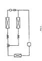
Figure 1 illustrates a refrigeration system including at least two evaporators connected in parallel belonging to the current state of the art; -
Figure 2 illustrates another refrigeration system comprising at least two evaporators connected in parallel belonging to the current state of the art; and -
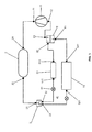
Figure 3 illustrates the refrigeration system including at least two evaporators connected in parallel according to the present invention. - Preliminarily, it should be clarified that, according to specialized literature, the evaporators can be classified according to their form of "power", that is, the evaporators can be defined as dry expansion evaporators, flooded evaporators or liquid over-feeding evaporators.
- The dry expansion evaporators are often "fed" by fluid previously turbulent refrigerant (liquid and vapor), and in its outflow, all the refrigerant is in the form of superheated steam. Flooded evaporators usually are "fed" by only the refrigerant in liquid form, it being at its output, all the refrigerant is in the form of dry saturated vapor fluid.
- Such arrangements are important for the fact that the refrigeration system including at least two evaporators associated in parallel now revealed is specially shaped to provide for a dry expansion evaporator associated in parallel with a flooded evaporator, and the "feeding" of an evaporator does not influence the "power" of the other evaporator.
- As illustrated in
Figure 3 , the refrigeration system including at least two evaporators associated in parallel, according to the present invention is primarily composed of acompressor 1, a condenser 2, a switching device 3 afirst expansion device 41, onesecond expansion device 42, adry expansion evaporator 51, a evaporates pain flooded 52 and aliquid accumulator 6. - The
compressor 1 is a compressor fundamentally conventional comprising asingle outflow 11 and asingle suction path 12. - The condenser 2 it is essentially a capacitor conventional comprising an
inlet path 21 and anoutflow 22. - The
switching device 3 is any device, comprising aninlet path 31 and at least twooutflows inlet path 31 with only one of the at least twooutflows device 3 it is fundamentally a conventionally three-way valve for two positions. - Both the
first expansion device 41 as thesecond expansion device 42 these are traditional expansion devices, and preferentially, conventional capillary tubes widely known to those skilled in the technical subject. - The
dry expansion evaporator 51, which is used as evaporator of a cooling chamber (not shown), or used as high pressure and low temperature evaporator, it is a traditional dry expansion evaporator fundamentally comprising aninlet path 511 and anoutflow 512. - The flooded
evaporator 52, which is used as an evaporator of a freezing chamber (not shown), this is, used as low pressure and very low temperature evaporator, it is flooded evaporator conventional, comprising aninlet path 521 andoutflow 522. - The
liquid accumulator 6, in turn, also is a liquid accumulator conventionally used in refrigeration systems, and comprises an airtight casing provided with at least one inlet through thebottom 61, by least oneupper inlet path 62 and at least onesuperior outflow 63. - In accordance with the subject invention, the
outflow 11 to thecompressor 1, is fluidly connected to theinlet path 21 to the condenser 2. Theoutflow 22 of the condenser 2 is fluidly connected to theinlet 31 of theswitching device 3. - The
outflow 32 of theswitching device 3 is fluidly connected to thefirst expansion device 41, which is connected to theinlet path 511 to thedry expansion evaporator 51. Theoutflow 512 of saiddry expansion evaporator 51 is fluidly connected to theupper inlet path 62 of theliquid accumulator 6. - The
outflow 33 of the switching device3 is fluidly connected to thesecond expansion device 42, which is connected to theinput 521 via the floodedevaporator 52. Theoutflow 522 of the aforementioned floodedevaporator 52 is fluidly connected to abottom inlet path 61 of theliquid accumulator 6. - The
upper outflow 63 ofliquid accumulator 6, in turn, is fluidly connected to thesuction path 12 of thecompressor 1. - It is worth mentioning that the fluid connections between the elements of the system as described above, are performed by traditional metal pipes means.
- Based on the above detailed arrangement, it is verified that the
liquid accumulator 6 ultimately perform two simultaneous functions, including: i) means of connection between theoutflows evaporators suction path 12 of thecompressor 1; and II) means of insulation between the evaporation line of thedry expansion evaporator 51 and the evaporation line of the floodedevaporator 52. - Once the
liquid accumulator 6 acts as a link between theevaporators compressor 1, it is clear that the invention in question facilitates the assembly of the system as a whole (seeFigure 2 ). - Once the
liquid tank 6 acts as a medium of isolation between rows of evaporation, it can be said that it is the major responsible for maintaining the independence between the evaporation lines and, in particular, maintaining the 52 always flooded evaporator flooded condition, even being the same not operating (depending on the operation of dry expansion evaporator 51). - Thus, when the
dry expansion evaporator 51 is operating (according to a certain position of the switching device 3), that is, when only thedry expansion evaporator 51 is being fed, thecompressor 1 tends to suck only steam superheated derived from saiddry expansion evaporator 51, and the floodedevaporator 52 is still flooded with coolant in which the liquid in the tank should be at its lowest level and the lower inlet always flooded. - When the flooded
evaporator 52 is operating (also due to a certain position of the switching device 3), that is, when only the floodedevaporator 52 is being fed,compressor 1 tends to suck, at first, both superheated steam arising from saiddry expansion evaporator 51 as dry saturated steam coming from the floodedevaporator 52, and, in a second time, only dry saturated steam coming from the floodedevaporator 52, and the refrigerant contained indry expansion evaporator 51 is completely drained and deposited in the accumulator at its maximum while maintaining the outflow to the compressor always with overheated steam. - That said, and that the above detailed operation proves extremely advantageous, it is important to note that the
liquid accumulator 6 has to be in a greater gravitational potential relative to the floodedevaporator 52, after all, the greatest potential gravitational ends to define a siphon effect between saidliquid accumulator 6 and the aforementioned floodedevaporator 52, preventing refrigerant liquid to change position when not suctioned. - However, it remains to show that the refrigeration system including at least two evaporators connected in parallel herein disclosed is also totally capable of operating independently of the greater gravitational potential of the
liquid accumulator 6 in relation to the floodedevaporator 52, after all, pressure difference between theevaporators dry expansion evaporator 51 being greater than the pressure of the flooded evaporator 52 (depending on specific dimensioning of theexpansion devices accumulator 6, and consequently throughout the floodedevaporator 52. - In more, remains to show that, preferentially, but not limiting, the
compressor 1 is about a compressor mainly conventionally capable to operate free of lubricants. Finally, it remains to show thatfigure 3 , and certain nomenclatures above used, are intended to illustrate the preferred embodiment of the invention in question, cannot be interpreted as limiting embodiment, after all, the scope of the invention in question must be considered as wide as the interpretation of the claims, further including the possible equivalent means.
Claims (5)
- Refrigeration system including at least two evaporators associated in parallel, where:said evaporators connected in parallel operate in different pressure and temperature ranges;said refrigeration system comprising at least two evaporators connected in parallel further comprising:at least one compressor (1), at least a condenser (2), at least a switching device (3) at least a first expansion device (41), at least a second expansion device (42), and at least one fluid accumulator (6);the outflow of the compressor being fluidly connected to the inlet path from the condenser; the condenser outflow being fluidly connected to the switching device inlet path; the switching device outflow being fluidly connected to the first expansion device; the switching device outflow is fluidly connected to the second expansion device;said liquid accumulator (6) comprising at least one lower inlet path (61) immersed in the liquid, at least one upper inlet path (62), and at least one upper outflow (63);said refrigeration system comprising at least two evaporators connected in parallel being particularly characterized in that further comprises:at least one dry expansion evaporator (51) acting as high pressure evaporator and low temperature and being fed by the first expansion device (41);at least a flooded evaporator (52) acting as a low pressure evaporator and very low temperature and being fed by the second expansion device (42); andthe outflow (512) of said dry expansion evaporator (51) being fluidly connected to the upper inlet path (62) of the liquid accumulator (6);the outflow (522) of said flooded evaporator (52) being fluidly connected to a lower inlet path (61) of the liquid accumulator (6); andthe upper outflow (63) of the liquid accumulator (6) being fluidly connected to the compressor suction path (1).
- Refrigeration system including at least two evaporators associated in parallel, as claimed in claim 1, characterized in that the fluid accumulator (6) is at a higher potential gravitational in relation to the flooded evaporator (52), so as to define a siphon effect between said liquid accumulator (6) and said flooded evaporator (52).
- Refrigeration system including at least two evaporators associated in parallel, as claimed in claim 1, characterized by the fact that the moving parts of the compression mechanism of compressor operate without lubrication by liquid means.
- Refrigeration system including at least two evaporators associated in parallel, as claimed in claim 1, characterized by the fact that the moving parts of the compressor compression mechanism cooperate with oil and at least one oil separator.
- Refrigeration system including at least two evaporators connected in parallel, as claimed in claim 1, characterized by the fact that said fluid accumulator (6) comprises at least one additional evaporator of a special compartment of the refrigeration system.
Applications Claiming Priority (1)
| Application Number | Priority Date | Filing Date | Title |
|---|---|---|---|
| BR102015017086A BR102015017086A2 (en) | 2015-07-16 | 2015-07-16 | cooling system including associated evaporators in parallel |
Publications (1)
| Publication Number | Publication Date |
|---|---|
| EP3121540A1 true EP3121540A1 (en) | 2017-01-25 |
Family
ID=56411479
Family Applications (1)
| Application Number | Title | Priority Date | Filing Date |
|---|---|---|---|
| EP16179277.5A Withdrawn EP3121540A1 (en) | 2015-07-16 | 2016-07-13 | Refrigeration system including evaporators associated in parallel |
Country Status (4)
| Country | Link |
|---|---|
| US (1) | US20170016652A1 (en) |
| EP (1) | EP3121540A1 (en) |
| CN (1) | CN106352580A (en) |
| BR (1) | BR102015017086A2 (en) |
Families Citing this family (10)
| Publication number | Priority date | Publication date | Assignee | Title |
|---|---|---|---|---|
| CN107990610A (en) * | 2018-01-18 | 2018-05-04 | 河南中瑞制冷科技有限公司 | A kind of industry water temperature double-control system |
| US11435124B2 (en) | 2018-02-28 | 2022-09-06 | Carrier Corporation | Refrigeration system with leak detection |
| CN109579335A (en) * | 2018-10-26 | 2019-04-05 | 青岛海尔股份有限公司 | Refrigeration system and refrigerator with the system |
| CN109579334A (en) * | 2018-10-26 | 2019-04-05 | 青岛海尔股份有限公司 | Low noise refrigerating system and refrigerator with the system |
| CN109579336B (en) * | 2018-10-26 | 2022-05-20 | 海尔智家股份有限公司 | Refrigerator noise reduction refrigerating system and refrigerator with same |
| DE102019201427B4 (en) * | 2019-02-05 | 2022-01-13 | Audi Ag | Method for operating a refrigerant circuit of a refrigeration system of a vehicle |
| US11879675B2 (en) * | 2020-01-15 | 2024-01-23 | Heatcraft Refrigeration Products Llc | Cooling system with flooded low side heat exchangers |
| DE102021201091A1 (en) * | 2021-02-05 | 2022-08-11 | Thyssenkrupp Ag | Compressors, in particular refrigerant compressors, refrigeration machines, and methods for producing a compressor |
| CN113340011B (en) * | 2021-06-08 | 2022-05-03 | 四川大学 | Heat exchanger rapid switching mechanism and method for refrigeration and heat pump circulating system |
| CN115406276B (en) * | 2022-08-03 | 2024-08-23 | 上海格熵航天科技有限公司 | Single heat source working medium consumption type cylindrical loop heat pipe |
Citations (6)
| Publication number | Priority date | Publication date | Assignee | Title |
|---|---|---|---|---|
| US2123497A (en) | 1936-11-11 | 1938-07-12 | Westinghouse Electric & Mfg Co | Two-temperature refrigerating apparatus |
| DE667699C (en) * | 1935-12-26 | 1938-11-18 | Sulzer Akt Ges Geb | Device for the return of oil in a refrigeration machine |
| US3108453A (en) | 1959-08-05 | 1963-10-29 | Mrs Bonita E Runde | Refrigerating apparatus including heat exchange stabilizer means |
| EP1087186A2 (en) | 1999-09-21 | 2001-03-28 | Kabushiki Kaisha Toshiba | Refrigerator with two evaporators |
| JP2006125769A (en) * | 2004-10-29 | 2006-05-18 | Denso Corp | Heat pump cycle equipment |
| EP2105686A2 (en) * | 2008-03-26 | 2009-09-30 | Sanyo Electric Co., Ltd. | Chiller unit, refrigeration system having chiller unit and air conditioner having chiller unit |
Family Cites Families (5)
| Publication number | Priority date | Publication date | Assignee | Title |
|---|---|---|---|---|
| US2133949A (en) * | 1935-03-30 | 1938-10-25 | Westinghouse Electric & Mfg Co | Refrigeration apparatus |
| US6176092B1 (en) * | 1998-10-09 | 2001-01-23 | American Standard Inc. | Oil-free liquid chiller |
| US7237395B2 (en) * | 2003-12-22 | 2007-07-03 | General Electric Company | Methods and apparatus for controlling refrigerators |
| DE102012020111A1 (en) * | 2011-10-19 | 2013-04-25 | Thermo Fisher Scientific (Asheville) LLC (n. d. Ges. d. Staates Delaware) | HIGH-PERFORMANCE COOLER WITH TWO EVAPORATORS |
| US9140480B2 (en) * | 2013-03-15 | 2015-09-22 | Whirlpool Corporation | Active insulation hybrid dual evaporator with rotating fan |
-
2015
- 2015-07-16 BR BR102015017086A patent/BR102015017086A2/en not_active Application Discontinuation
-
2016
- 2016-07-13 EP EP16179277.5A patent/EP3121540A1/en not_active Withdrawn
- 2016-07-15 CN CN201610560733.XA patent/CN106352580A/en active Pending
- 2016-07-15 US US15/211,419 patent/US20170016652A1/en not_active Abandoned
Patent Citations (6)
| Publication number | Priority date | Publication date | Assignee | Title |
|---|---|---|---|---|
| DE667699C (en) * | 1935-12-26 | 1938-11-18 | Sulzer Akt Ges Geb | Device for the return of oil in a refrigeration machine |
| US2123497A (en) | 1936-11-11 | 1938-07-12 | Westinghouse Electric & Mfg Co | Two-temperature refrigerating apparatus |
| US3108453A (en) | 1959-08-05 | 1963-10-29 | Mrs Bonita E Runde | Refrigerating apparatus including heat exchange stabilizer means |
| EP1087186A2 (en) | 1999-09-21 | 2001-03-28 | Kabushiki Kaisha Toshiba | Refrigerator with two evaporators |
| JP2006125769A (en) * | 2004-10-29 | 2006-05-18 | Denso Corp | Heat pump cycle equipment |
| EP2105686A2 (en) * | 2008-03-26 | 2009-09-30 | Sanyo Electric Co., Ltd. | Chiller unit, refrigeration system having chiller unit and air conditioner having chiller unit |
Also Published As
| Publication number | Publication date |
|---|---|
| CN106352580A (en) | 2017-01-25 |
| BR102015017086A2 (en) | 2017-01-24 |
| US20170016652A1 (en) | 2017-01-19 |
Similar Documents
| Publication | Publication Date | Title |
|---|---|---|
| EP3121540A1 (en) | Refrigeration system including evaporators associated in parallel | |
| US10634424B2 (en) | Oil management for micro booster supermarket refrigeration system | |
| EP2787305B1 (en) | Refrigerating/air-conditioning device | |
| JP2017531156A (en) | Refrigeration cycle equipment | |
| KR100846567B1 (en) | Refrigerating apparatus | |
| JP6349417B2 (en) | Two-stage rotary compressor and cooling cycle equipment | |
| EP2865970A1 (en) | Freezer | |
| US20090229300A1 (en) | Refrigeration System | |
| KR101429363B1 (en) | Oil-cooled two-stage compressor and heat pump | |
| JP6498299B2 (en) | Refrigeration cycle equipment | |
| JP2009228976A (en) | Refrigerating cycle device | |
| JP5279105B1 (en) | Start-up control method for dual refrigeration system | |
| JP3861913B1 (en) | Refrigeration equipment | |
| CN204757427U (en) | High -efficient refrigerating unit | |
| JP5975742B2 (en) | Refrigeration equipment | |
| EP2762803A2 (en) | Two-stage compression device and chilling/air-conditioning device using the same | |
| JP2016161190A (en) | Refrigeration equipment and heat pump | |
| EP3611442A1 (en) | Gas-liquid separation unit for refrigeration device, and refrigeration device | |
| US10203144B2 (en) | Refrigeration device comprising a refrigerant circuit with a multi suction line | |
| EP1616136B1 (en) | Refrigeration system and a method for operating such system | |
| US12345451B2 (en) | Refrigeration system | |
| KR200233880Y1 (en) | Condenser combined with Receiver Tank | |
| WO2011101029A1 (en) | Refrigeration system and method for balancing the oil levels between compressors of a refrigeration system | |
| JPH02230985A (en) | Parallel compression type refrigerator | |
| Ariyo et al. | Performance of an improved household refrigerator/freezer |
Legal Events
| Date | Code | Title | Description |
|---|---|---|---|
| PUAI | Public reference made under article 153(3) epc to a published international application that has entered the european phase |
Free format text: ORIGINAL CODE: 0009012 |
|
| AK | Designated contracting states |
Kind code of ref document: A1 Designated state(s): AL AT BE BG CH CY CZ DE DK EE ES FI FR GB GR HR HU IE IS IT LI LT LU LV MC MK MT NL NO PL PT RO RS SE SI SK SM TR |
|
| AX | Request for extension of the european patent |
Extension state: BA ME |
|
| 17P | Request for examination filed |
Effective date: 20170724 |
|
| RBV | Designated contracting states (corrected) |
Designated state(s): AL AT BE BG CH CY CZ DE DK EE ES FI FR GB GR HR HU IE IS IT LI LT LU LV MC MK MT NL NO PL PT RO RS SE SI SK SM TR |
|
| 17Q | First examination report despatched |
Effective date: 20171205 |
|
| STAA | Information on the status of an ep patent application or granted ep patent |
Free format text: STATUS: THE APPLICATION IS DEEMED TO BE WITHDRAWN |
|
| 18D | Application deemed to be withdrawn |
Effective date: 20180417 |