EP3121442B2 - Operating wind turbines - Google Patents
Operating wind turbines Download PDFInfo
- Publication number
- EP3121442B2 EP3121442B2 EP15382372.9A EP15382372A EP3121442B2 EP 3121442 B2 EP3121442 B2 EP 3121442B2 EP 15382372 A EP15382372 A EP 15382372A EP 3121442 B2 EP3121442 B2 EP 3121442B2
- Authority
- EP
- European Patent Office
- Prior art keywords
- wind
- wind turbine
- parameters
- wake
- determining
- Prior art date
- Legal status (The legal status is an assumption and is not a legal conclusion. Google has not performed a legal analysis and makes no representation as to the accuracy of the status listed.)
- Active
Links
- 238000000034 method Methods 0.000 claims description 72
- 230000006735 deficit Effects 0.000 claims description 17
- 230000006870 function Effects 0.000 claims description 13
- 238000005259 measurement Methods 0.000 claims description 11
- 238000012795 verification Methods 0.000 claims description 9
- 238000005457 optimization Methods 0.000 claims description 8
- 230000009467 reduction Effects 0.000 description 7
- 238000010248 power generation Methods 0.000 description 6
- 238000004422 calculation algorithm Methods 0.000 description 4
- 238000004364 calculation method Methods 0.000 description 4
- 230000000694 effects Effects 0.000 description 4
- 230000006399 behavior Effects 0.000 description 2
- 238000001514 detection method Methods 0.000 description 2
- 238000009826 distribution Methods 0.000 description 2
- 230000001960 triggered effect Effects 0.000 description 2
- 238000012935 Averaging Methods 0.000 description 1
- 230000009471 action Effects 0.000 description 1
- 238000004458 analytical method Methods 0.000 description 1
- 230000002238 attenuated effect Effects 0.000 description 1
- 230000008859 change Effects 0.000 description 1
- 238000004590 computer program Methods 0.000 description 1
- 230000003750 conditioning effect Effects 0.000 description 1
- 238000010276 construction Methods 0.000 description 1
- 238000011217 control strategy Methods 0.000 description 1
- 230000002950 deficient Effects 0.000 description 1
- 230000001419 dependent effect Effects 0.000 description 1
- 230000005611 electricity Effects 0.000 description 1
- 238000009434 installation Methods 0.000 description 1
- 230000003993 interaction Effects 0.000 description 1
- 238000004519 manufacturing process Methods 0.000 description 1
- 238000012986 modification Methods 0.000 description 1
- 230000004048 modification Effects 0.000 description 1
- 238000012544 monitoring process Methods 0.000 description 1
- 230000008569 process Effects 0.000 description 1
- 238000012545 processing Methods 0.000 description 1
- 238000003860 storage Methods 0.000 description 1
Images

Classifications
-
- F—MECHANICAL ENGINEERING; LIGHTING; HEATING; WEAPONS; BLASTING
- F03—MACHINES OR ENGINES FOR LIQUIDS; WIND, SPRING, OR WEIGHT MOTORS; PRODUCING MECHANICAL POWER OR A REACTIVE PROPULSIVE THRUST, NOT OTHERWISE PROVIDED FOR
- F03D—WIND MOTORS
- F03D7/00—Controlling wind motors
- F03D7/02—Controlling wind motors the wind motors having rotation axis substantially parallel to the air flow entering the rotor
- F03D7/04—Automatic control; Regulation
- F03D7/042—Automatic control; Regulation by means of an electrical or electronic controller
- F03D7/048—Automatic control; Regulation by means of an electrical or electronic controller controlling wind farms
-
- F—MECHANICAL ENGINEERING; LIGHTING; HEATING; WEAPONS; BLASTING
- F03—MACHINES OR ENGINES FOR LIQUIDS; WIND, SPRING, OR WEIGHT MOTORS; PRODUCING MECHANICAL POWER OR A REACTIVE PROPULSIVE THRUST, NOT OTHERWISE PROVIDED FOR
- F03D—WIND MOTORS
- F03D17/00—Monitoring or testing of wind motors, e.g. diagnostics
-
- F—MECHANICAL ENGINEERING; LIGHTING; HEATING; WEAPONS; BLASTING
- F03—MACHINES OR ENGINES FOR LIQUIDS; WIND, SPRING, OR WEIGHT MOTORS; PRODUCING MECHANICAL POWER OR A REACTIVE PROPULSIVE THRUST, NOT OTHERWISE PROVIDED FOR
- F03D—WIND MOTORS
- F03D7/00—Controlling wind motors
- F03D7/02—Controlling wind motors the wind motors having rotation axis substantially parallel to the air flow entering the rotor
- F03D7/04—Automatic control; Regulation
- F03D7/042—Automatic control; Regulation by means of an electrical or electronic controller
- F03D7/043—Automatic control; Regulation by means of an electrical or electronic controller characterised by the type of control logic
- F03D7/045—Automatic control; Regulation by means of an electrical or electronic controller characterised by the type of control logic with model-based controls
-
- F—MECHANICAL ENGINEERING; LIGHTING; HEATING; WEAPONS; BLASTING
- F03—MACHINES OR ENGINES FOR LIQUIDS; WIND, SPRING, OR WEIGHT MOTORS; PRODUCING MECHANICAL POWER OR A REACTIVE PROPULSIVE THRUST, NOT OTHERWISE PROVIDED FOR
- F03D—WIND MOTORS
- F03D9/00—Adaptations of wind motors for special use; Combinations of wind motors with apparatus driven thereby; Wind motors specially adapted for installation in particular locations
- F03D9/20—Wind motors characterised by the driven apparatus
- F03D9/25—Wind motors characterised by the driven apparatus the apparatus being an electrical generator
- F03D9/255—Wind motors characterised by the driven apparatus the apparatus being an electrical generator connected to electrical distribution networks; Arrangements therefor
- F03D9/257—Wind motors characterised by the driven apparatus the apparatus being an electrical generator connected to electrical distribution networks; Arrangements therefor the wind motor being part of a wind farm
-
- G—PHYSICS
- G05—CONTROLLING; REGULATING
- G05B—CONTROL OR REGULATING SYSTEMS IN GENERAL; FUNCTIONAL ELEMENTS OF SUCH SYSTEMS; MONITORING OR TESTING ARRANGEMENTS FOR SUCH SYSTEMS OR ELEMENTS
- G05B13/00—Adaptive control systems, i.e. systems automatically adjusting themselves to have a performance which is optimum according to some preassigned criterion
- G05B13/02—Adaptive control systems, i.e. systems automatically adjusting themselves to have a performance which is optimum according to some preassigned criterion electric
- G05B13/04—Adaptive control systems, i.e. systems automatically adjusting themselves to have a performance which is optimum according to some preassigned criterion electric involving the use of models or simulators
- G05B13/041—Adaptive control systems, i.e. systems automatically adjusting themselves to have a performance which is optimum according to some preassigned criterion electric involving the use of models or simulators in which a variable is automatically adjusted to optimise the performance
-
- F—MECHANICAL ENGINEERING; LIGHTING; HEATING; WEAPONS; BLASTING
- F05—INDEXING SCHEMES RELATING TO ENGINES OR PUMPS IN VARIOUS SUBCLASSES OF CLASSES F01-F04
- F05B—INDEXING SCHEME RELATING TO WIND, SPRING, WEIGHT, INERTIA OR LIKE MOTORS, TO MACHINES OR ENGINES FOR LIQUIDS COVERED BY SUBCLASSES F03B, F03D AND F03G
- F05B2270/00—Control
- F05B2270/10—Purpose of the control system
- F05B2270/20—Purpose of the control system to optimise the performance of a machine
- F05B2270/204—Purpose of the control system to optimise the performance of a machine taking into account the wake effect
-
- F—MECHANICAL ENGINEERING; LIGHTING; HEATING; WEAPONS; BLASTING
- F05—INDEXING SCHEMES RELATING TO ENGINES OR PUMPS IN VARIOUS SUBCLASSES OF CLASSES F01-F04
- F05B—INDEXING SCHEME RELATING TO WIND, SPRING, WEIGHT, INERTIA OR LIKE MOTORS, TO MACHINES OR ENGINES FOR LIQUIDS COVERED BY SUBCLASSES F03B, F03D AND F03G
- F05B2270/00—Control
- F05B2270/80—Devices generating input signals, e.g. transducers, sensors, cameras or strain gauges
- F05B2270/804—Optical devices
- F05B2270/8042—Lidar systems
-
- Y—GENERAL TAGGING OF NEW TECHNOLOGICAL DEVELOPMENTS; GENERAL TAGGING OF CROSS-SECTIONAL TECHNOLOGIES SPANNING OVER SEVERAL SECTIONS OF THE IPC; TECHNICAL SUBJECTS COVERED BY FORMER USPC CROSS-REFERENCE ART COLLECTIONS [XRACs] AND DIGESTS
- Y02—TECHNOLOGIES OR APPLICATIONS FOR MITIGATION OR ADAPTATION AGAINST CLIMATE CHANGE
- Y02E—REDUCTION OF GREENHOUSE GAS [GHG] EMISSIONS, RELATED TO ENERGY GENERATION, TRANSMISSION OR DISTRIBUTION
- Y02E10/00—Energy generation through renewable energy sources
- Y02E10/70—Wind energy
- Y02E10/72—Wind turbines with rotation axis in wind direction
Definitions
- the present disclosure relates to methods of operating a first wind turbine and a second wind turbine in a situation wherein presence of the first wind turbine affects the wind so that a wake is generated that affects the second wind turbine.
- the present disclosure further relates to control systems for operating a plurality of wind turbines, and to wind farms including any of such control systems.
- Wind turbines are commonly used to supply electricity into the electrical grid.
- Wind turbines generally comprise a rotor with a rotor hub and a plurality of blades.
- the rotor is set into rotation under the influence of the wind on the blades.
- the rotation of a rotor shaft drives a generator rotor either directly (“directly driven") or through the use of a gearbox.
- the gearbox (if present), the generator and other systems are usually mounted in a nacelle on top of a wind turbine tower.
- Wind turbines are often grouped together in so-called wind farms.
- a wind farm is to be regarded as a cluster of two or more wind turbines.
- action of the wind on one wind turbine may produce a wake which may be received by another wind turbine.
- a wake received by a wind turbine may cause loads (particularly vibrations) and/or a reduction of electrical power production in this wind turbine. These loads may damage components of the wind turbine, and this damage may reduce the life and/or the performance of the wind turbine. Therefore, in a wind farm, monitoring is carried out in order to determine possible wake situations and the wind turbines are operated in order to minimize negative effects caused by the wakes.
- Some wake management strategies are defined by simulating operational conditions (e.g. loads, generated power, etc.) for a theoretical layout and parameters of the wind. For every wind turbine in the layout, a set of adjustments in the operation of the wind turbine (e.g. stops, curtailments) is defined for predetermined wind directions in order to perform an operation of the wind turbine as optimal as possible. Optimal operation may be in terms of e.g. producing maximum power, minimizing loads, etc. depending on the main goal pursued at each moment. These adjustments are entered in a control system (e.g. a SCADA control system) which applies them in the wind farm by e.g. sending suitable control signals to e.g. the corresponding pitch systems, brakes, etc.
- a control system e.g. a SCADA control system
- An optimizing algorithm may be used to improve the performance of at least part of the wind farm based on the interaction between wind turbines.
- Wake effects may be detected and evaluated by using one or more theoretical wake models including empirical factors (parameters, constants, etc.) which are predefined based on previous experience at existing wind farms (e.g. from operational data collected from before installation of the wind farm).
- This way of computing wakes may produce results that greatly diverge from what is actually happening between wind turbines due to variations of characteristics of the environment. For instance, the air density may vary, the geography may change due to e.g. trees growing and/or constructions erected in the vicinity of the wind turbines, etc.
- the models themselves, which are based on existing wind farms may not be appropriate for the wind farm under consideration as particular conditions of the existing wind farms may not be applicable. This divergence may cause deficient operation of the wind turbines and the wind farm as a whole.
- the invention provides methods of operating a first wind turbine and a second wind turbine in a situation wherein presence of the first wind turbine affects the wind so that a wake is generated that affects the second wind turbine in accordance with any of independent claims 1, 4 and 6. Embodiments are set out in the dependent claims.
- the methods comprise determining one or more parameters of the wind at the first wind turbine, and determining one or more parameters of the wind at the second wind turbine.
- the methods further comprise determining a value of a parameter of a theoretical wake model to determine a current wake model. This value is determined based on the one or more parameters of the wind at the first wind turbine, and on the one or more parameters of the wind at the second wind turbine.
- the method still further comprises optimizing the operation of the first and second wind turbines based on the current wake model.
- the method may further comprise determining a divergence between a previously determined wake model and the current wake model, and verifying whether said divergence exceeds a predefined threshold. In case of negative result of said verification, the previously determined wake model may be taken as the current wake model.
- the previously determined wake model may be either a wake model determined in a previous execution (or iteration) of the method (i.e. based on real parameters of the wind at the first and second wind turbines) or a baseline wake model.
- the previously determined wake model may be the wake model that has been determined most recently in a preceding execution (or iteration) of the method.
- the baseline wake model may refer to a wake model that has been predetermined based on data other than real parameters of the wind (at the first and second wind turbines) because e.g. no execution of the method has still been performed.
- the baseline wake model may have been determined based on e.g. data from other wind farms. Once a first execution (or iteration) of the method has been performed, the baseline wake model may not be used anymore. In this case, a wake model determined in a previous iteration or execution of the method may be used instead of the baseline wake model.
- Determining parameters of the wind at first and second wind turbines may comprise determining wind speed and/or wind turbulence and/or wind direction at first and second wind turbines. Other parameters are also possible.
- Obtained wind speeds may be used to calculate a value of wind speed deficit, which may be compared to a wind speed deficit obtained from a wake model such as e.g. Jensen model.
- obtained wind turbulences may be used to calculate a value of added wind turbulence, which may be compared to an added turbulence obtained from a wake model such as e.g. Frandsen model.
- the current wake model may be determined from a theoretical wake model based on real operational data (parameters of the wind) determined at first and second wind turbines participating in the wake.
- Said real operational data may comprise e.g. wind speed at first and second wind turbines, from which a real speed deficit may be calculated.
- a theoretical wake model may comprise an analytical function expressing the speed deficit depending on a factor (or constant). Determining the current wake model may comprise calculating a value for said factor/constant that makes the analytical function (of the theoretical wake model) to produce a speed deficit substantially equal to the "measured" real speed deficit.
- the current wake model may be seen as a particular version of the theoretical wake model including the recalculated factor/constant. Which parameter or property of the wind is to be taken into account depends on the theoretical model used for describing wake behaviour.
- Jensen model comprises an analytical function mathematically expressing the speed deficit depending on variables, such as e.g. rotor diameter and thrust coefficient, and on a predefined decay constant. A new value for the decay constant of the Jensen model may be calculated that produces the real speed deficit calculated from the real wind speeds measured at first and second wind turbines.
- Other theoretical wake models may comprise other analytical functions including other empirical factors or constants that may also be recalculated based on real parameters of the wind.
- Frandsen turbulence model comprises an analytical function mathematically expressing added wind turbulence.
- Other wake models that can be used in the context of the suggested method are e.g. Larsen model and Ainslie model.
- the proposed method of operating first and second wind turbines is based on determining a current wake model depending on real parameters of the wind measured at first and second wind turbines. Then, the current wake model may be inputted in an optimization process to optimize the operation of the wind turbines.
- An aspect of the method may thus be that wind turbines are operated more optimally because wake is modelled depending on real operational data (parameters of the wind) rather than on predefined data.
- determining a current wake model describing the behaviour of a wake in a certain wind farm may be done in real-time.
- the parameters of the wind at the first and second wind turbines are determined depending on one or more measurements from a LIDAR associated with the wind turbines.
- the LIDAR may be arranged in the vicinity of the wind turbines in e.g. a frontal position, such that parameters of the wind received by the wind turbines may be reliably measured.
- At least some of the parameters of the wind at any of the first and second wind turbines may also be determined depending on one or more operational characteristics of the wind turbine. These operational characteristics may comprise at least one of: pitch angle, yaw angle, rotor speed, rotor torque and generated power. Wind turbines may comprise sensors configured to obtain measures that permit determining such operational characteristics when required.
- the parameters of the wind at any of the first and second wind turbines are determined depending on one or more loads measured at the wind turbine.
- Wind turbines may comprise load sensors through which said load measurements are obtained.
- a particular wind parameter may be determined through any one of the previously described manners or through a combination thereof.
- the different values obtained for the wind parameter may be averaged such that a more reliable value of the parameter is obtained.
- the different values of the parameter may be suitably weighted in said averaging depending on an estimated reliability of the algorithm used to determine every value of the wind parameter.
- the first and second wind turbines may be operated by controlling one or more operational parameters of the wind turbine.
- Optimum values of the operational parameters may be obtained either from one or more matrices (or lookup tables), or from one or more functions, or from a combination of both.
- Optimum values of the operational parameters may be those that maximize parameters of an optimization objective depending on parameters of the current wake model.
- optimum values of the operational parameters may be those that maximize e.g. the generation of power or the reduction of loads depending on the current wake model.
- methods of operating a plurality of wind turbines may be provided. These methods may comprise detecting one or more pairs of the wind turbines having a first wind turbine and a second wind turbine in a situation wherein presence of the first wind turbine affects the wind so that a wake is generated that affects the second wind turbine. These methods may further comprise operating, for at least some of the detected pairs of wind turbines, the first and second wind turbines of the pair of wind turbines by performing any of the methods of operating first and second wind turbines according to claim 1, 4 or 6. At least one of the pairs of wind turbines may be detected depending on a previously determined wake model for the first and second wind turbines of the pair of wind turbines, so that said detection may be based on more real data and therefore may be more reliable.
- the previously determined wake model may be the wake model determined in the most recent execution (or iteration) of the method.
- control systems for operating a plurality of wind turbines which e.g. may be comprised in a wind farm.
- These control systems comprise a processor and a memory.
- the memory stores computer executable instructions that, when executed, cause the processor to perform methods of operating a plurality of wind turbines according to claim 9.
- wind farms comprising a plurality of wind turbines and any one of the previously described control systems.
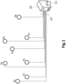
- FIG 1 is a schematic representation of a wind farm according to an example.
- This wind farm may comprise a plurality of wind turbines T1 - T8, which are conceptually represented in the figure as circles.
- Each or some of these wind turbines may have different types of sensors (not shown) such as e.g. load sensors, LIDARs, yaw sensors, etc.
- the wind farm may also comprise an example of a control system 10 for operating all or part of the wind turbines T1 - T8 as a whole.
- the wind turbines T1 - T8 may be theoretically distributed within the wind farm according to a theoretical layout.
- a met pole may be included in the wind park for measuring wind and ambient conditions (e.g. temperature, wind direction, turbulence, wind speed, humidity etc.).
- the control system 10 may be connected 12 with the wind turbines T1 - T8, such that the control system 10 may receive measurements (e.g. load measurements, wind measurements, yaw measurements, etc.) from sensors associated with some or all of the wind turbines T1 - T8.
- the control system 10 may also send, through the connection 12, proper signals (e.g. set points) to the wind turbines T1 - T8 for adjusting their operation as a whole.
- the control system 10 may comprise a memory and a processor.
- the memory may store computer program instructions executable by the processor. Said instructions may comprise functionality to execute one or more examples of a method of operating a plurality of wind turbines, which are described in other parts of the description.
- the control system 10 may further comprise a repository 11 for obtaining and storing data related to wind turbines T1 - T8, such as e.g. the layout of the wind farm, distances between wind turbines, dimensions of the wind turbines, theoretical wake models, control strategies, etc.
- Each or some of the wind turbines T1 - T8 may have an individual controller configured to operate the wind turbine depending on individual parameters and control signals (set points) received from the control system 10. These individual controllers may control operational parameters (pitch angle, rotor speed, rotor torque, etc.) of the wind turbine in such a way that set points from the control system 10 and individual requirements are satisfied.
- FIG 2a is a schematic representation of a wind farm similar to the one of Figure 1 , wherein a wake situation/scenario is illustrated between first and second wind turbines resulting in a wind speed deficit.
- a wake situation/scenario is illustrated between first and second wind turbines resulting in a wind speed deficit.
- FIG. 2a it is shown that presence of the wind turbine T8 may affect the wind 200 so that a wake 205 is generated that affects the wind turbine T7.
- wind passing through the rotor of the wind turbine T8 is shown suffering a reduction of its speed 202.
- Wind passing surrounding the rotor of wind turbine T8 is shown maintaining its wind speed substantially unchanged 201, but this is not necessarily the case.
- the wind with substantially unchanged speed 203 is shown passing surrounding the rotor of wind turbine T7.
- the wind with reduced speed 204 is shown influencing the rotor of the wind turbine T7, such that e.g. less power is generated by the wind turbine T7.
- An excessively reduced wind speed 204 may cause the stop of the wind turbine T7.
- An objective of an example of a method of operating first and second wind turbines T7, T8 may be maximizing power generation by the wind turbines T7, T8 as a whole, and this may be achieved by e.g. avoiding the stop of the wind turbines T7, T8.
- said method may suitably vary the operation of the wind turbine T8 in such a way that the wind speed 204 is less reduced so that the stop of the wind turbine T7 is avoided.
- Turbines T7, T8 may thus be operated by the proposed method in such a way that their performance is improved as a whole.
- Jensen model is an example of theoretical wake model which describes the wind speed deficit schematically illustrated by Figure 2a .
- FIG 2b is a schematic representation of a wind farm similar to the one of Figure 1 , wherein a turbulence increase (added turbulence) is illustrated between first and second wind turbines as a result of the wake effect. It is shown that the presence of the wind turbine T8 may affect the wind 206 so that a wake 211 is generated that affects the wind turbine T7.
- the wind 206 is represented with a certain level of turbulence through slightly wavy arrows. Wind passing through the rotor of the wind turbine T8 is shown with an increased turbulence 208. Wind passing surrounding the rotor of the wind turbine T8 is shown maintaining its level of turbulence substantially unchanged 207, but this is not necessarily the case.
- the wind without added turbulence 209 is shown passing surrounding the rotor of the wind turbine T7.
- the wind with added turbulence 210 is shown influencing the rotor of the wind turbine T7, such that e.g. higher loads are suffered by the wind turbine T7.
- Excessively increased wind turbulence 210 may cause too high loads on the wind turbine T7 and its individual operation may be varied accordingly with the aim of reducing such loads. This variation of the individual operation may cause a reduction of power generation or even the stop of the wind turbine T7.
- An objective of an example of a method of operating first and second wind turbines T7, T8 may be maximizing power generation by the wind turbines T7, T8 as a whole.
- This objective may be achieved by avoiding the reduction of power generation by wind turbine T7 and/or the stop of the wind turbine T7.
- said method may cause operation of the wind turbine T8 in such a way that e.g. the added turbulence 208 and its affectation on the wind turbine T7 are attenuated.
- Turbines T7, T8 may thus be operated by the proposed method in such a way that their performance is improved as a whole.
- an objective of an example of a method of operating first and second wind turbines T7, T8 may be limiting loads suffered by T7.
- Frandsen model is an example of theoretical wake model which models the effect of added turbulence schematically illustrated by Figure 2b .
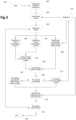
- Figure 3 is a flow chart of an example of a method of operating a wind farm according to an implementation.
- the method may be initiated at initial block 300 which may be triggered upon reception of a user request, as a result of an automatic triggering, upon detection of a triggering condition, etc.
- parameters representative of weather conditions at the wind farm site may be obtained from a reference mast or similar arranged at wind farm level. Parameters of the wind (speed and direction) may be systematically measured and obtained, whereas other parameters (wind turbulence, temperature or density) might optionally also be acquired.
- DB Database
- DB 315 for later use, such as e.g. for empirical analysis of wind farm data. If just a short time has elapsed since the last execution of block 301, recent data on parameters of the wind and possibly other aspects may be obtained from DB 315 instead of from the reference mast.
- wake situations in the wind farm may be identified from the ambient data obtained at block 301 and one or more surrogate models associated with the wind farm from DB 315.
- Situations in that wind conditions i.e. wind speed and wind direction
- a first wind turbine causes a wake affecting a second wind turbine may be detected by processing data from block 301 and data from DB 315.
- Surrogate model may include geometrical data, i.e. layout of the wind farm including distribution of wind turbines, distances between wind turbines, dimensions of wind turbines, etc.
- Surrogate model may further comprise wake model(s) that can be used to model and estimate presence and relevance of wake situations substantially in real time.
- a theoretical wake model may include parameters characterizing e.g. wind turbines and their distribution, and empirical factors theoretically conditioning the occurrence and magnitude of wakes. Said empirical factors may be predefined based on previous experience (empirical data) from known wind farms, thus resulting in a baseline wake model.
- Block 302 may produce a set of pairs of wind turbines with a wake between them which may distort the operation and power generation of the wind farm as a whole.
- a wake model determined in a previous execution of the method may be retrieved from DB 315 and used instead of the baseline wake model for identifying wake situations.
- a previous execution (or iteration) of the proposed method may have produced a wake model from current real wind data determined at first and second wind turbines and may have stored said previously determined wake model in DB 315 for later use.
- the wake model retrieved from DB 315 may be the one generated most recently for the first and second wind turbines that are being processed. In that sense, note that different areas of a wind farm may have varying characteristics, so different wake models may be applicable to each of those differentiated areas.
- one of the pairs of wind turbines detected at previous block 302 may be selected to be processed in subsequent blocks.
- one or more wind parameters may be determined at first wind turbine which is creating the wake.
- one or more wind parameters may be determined at second wind turbine which is receiving the wake.
- the one or more wind parameters may comprise one of the wind speed, wind turbulence and wind direction.
- wind speed and/or wind turbulence at a wind turbine are determined depending on measurements from a LIDAR associated with the first and second wind turbines.
- Individual controller of a wind turbine may operate the wind turbine by controlling operational parameters such as e.g. pitch angle, yaw angle, rotor speed, torque and generated power based on measurements obtained at the wind turbine.
- wind speed and/or wind turbulence may be indirectly determined at a wind turbine from at least some of said operational parameters controlled by the individual controller of the wind turbine.
- a wind turbine may also comprise load sensors for determining loads on the wind turbine.
- wind speed and/or wind turbulence are indirectly determined at a wind turbine from load measurements provided by said load sensors.
- a previously determined wake model having a parameter with a predetermined value for the first and second wind turbines may be retrieved from DB 315.
- the previously determined wake model may be either a baseline wake model or a wake model determined in a previous execution or iteration of the method.
- a current wake model may be determined by calculating a value of the parameter of the theoretical wake model based on the obtained wind parameter(s) at first and second wind turbines.
- a real (experimental) magnitude may be obtained.
- this real magnitude may refer to wind speed deficit on the second wind turbine.
- wind speed deficit is obtainable from the Jensen wake model.
- the obtained real magnitude may refer to added wind turbulence on the second wind turbine, i.e. an amount of added turbulence received by the downwind (second) wind turbine from the upwind (first) wind turbine.
- added wind turbulence may be determined by using the Frandsen wake model.
- a value of a constant or factor of the theoretical wake model may be calculated. Said calculation of the constant or factor may be performed based on the real (experimental) magnitude obtained from the real wind parameter(s) determined at first and second wind turbines.
- the constant to be calculated may be the "decay constant" which depends on predefined data (roughness of the ground surface and height of the wind turbine tower) in the analytical function of the model.
- the Jensen model may thus be used in methods not covered by claim 1 to calculate the decay constant in such a way that the analytical function produces a wind speed deficit substantially equal to the obtained real magnitude of the wind speed deficit (depending on real wind speed at first and second wind turbines).
- This calculated decay constant may be used in subsequent calculations of the proposed method, such as e.g. those aimed at optimizing the operation of first and second wind turbines.
- the previously determined wake model (obtained from DB 315) and the current wake model (determined from current real wind data) may be compared.
- a verification of whether the comparison performed at block 308 produces a divergence that exceeds a predefined threshold may be performed.
- the method may continue to block 311 at which the current wake model (determined from current real wind data) is provided to block 312 of optimizing the operation of first and second wind turbines.
- the method may continue to block 310 at which the previously determined wake model is taken as the current wake model and therefore provided to block 312 of optimizing the operation of first and second wind turbines.
- the current wake model (determined from current real wind data) may be also provided to DB 315 for its storage, so that later executions or iterations of the method may re-use said wake model at block 306.
- An aspect of this re-utilization of wake models determined in previous executions or iterations of the method is that wakes may be estimated based on more real conditions.
- the previously determined wake model and the current wake model may be taken as the current wake model and therefore used in subsequent calculations. Since the previously determined wake model has been already used (in previous executions of the method) its selection for subsequent calculations may require relatively less computational effort.
- first and second wind turbines may be optimized taking into account the current wake model, which may have been obtained from current real wind data (at first and second wind turbines) or may be the previously determined wake model, depending on the result of the verification performed at block 309.
- Optimum operating parameters such as e.g. pitch, torque, rpms, yaw, etc. may be generated for both first and second wind turbines depending on the current wake model. Said optimization may be performed depending on an objective, such as e.g. maximizing power generation, maximizing loads reduction, etc. This optimization may be performed by using matrices or look-up tables having input and output parameters.
- Input parameters may comprise those parameters characterizing the current operational state of wind turbines, the operational objective to be achieved, etc.
- Output parameters may comprise those operating parameters (pitch, torque, rpms, etc.) to be controlled for operating the wind turbine.
- the decay constant of the current wake model may be one of the input parameters such that output parameters may be determined depending on said decay constant.
- Any known optimizing algorithm may be used to select the most optimum output parameters according to the objective to be achieved which is represented in the matrices (or look up tables) in the form of input parameters.
- suitable analytical function(s) may be used for optimizing the operation of first and second wind turbines.
- output parameters to be controlled may be expressed as a function of input parameters such as e.g. factor or constant of the corresponding wake model.
- an output parameter (pitch, rpms, torque%) may be expressed as a function of the decay constant and other parameters such as e.g. variables characterizing the objective to be achieved (maximum power, maximum loads reduction, ). Any known optimizing algorithm may be used to optimize such analytical functions.
- control signals may be sent to wind turbine actuators to operate the first and second wind turbines according to the obtained optimum operating parameters.
- a verification of whether all the pairs of wind turbines detected at block 302 have been processed may be performed. In case of negative result of said verification, the method may loop back to block 303 in order to select a next pair of wind turbines to be processed. In case of positive result of said verification, the method may continue to final block 314.
- the method may end its execution. From this point, the initial block 300 may be triggered again in order to perform a new iteration or execution of the method, such that the method may continuously iterate under a given frequency, for example.
Description
- The present disclosure relates to methods of operating a first wind turbine and a second wind turbine in a situation wherein presence of the first wind turbine affects the wind so that a wake is generated that affects the second wind turbine. The present disclosure further relates to control systems for operating a plurality of wind turbines, and to wind farms including any of such control systems.
- Modern wind turbines are commonly used to supply electricity into the electrical grid. Wind turbines generally comprise a rotor with a rotor hub and a plurality of blades. The rotor is set into rotation under the influence of the wind on the blades. The rotation of a rotor shaft drives a generator rotor either directly ("directly driven") or through the use of a gearbox. The gearbox (if present), the generator and other systems are usually mounted in a nacelle on top of a wind turbine tower.
- Wind turbines are often grouped together in so-called wind farms. In the present disclosure, a wind farm is to be regarded as a cluster of two or more wind turbines. In a wind farm there may be a relatively short distance between wind turbines. Thus, action of the wind on one wind turbine may produce a wake which may be received by another wind turbine. A wake received by a wind turbine may cause loads (particularly vibrations) and/or a reduction of electrical power production in this wind turbine. These loads may damage components of the wind turbine, and this damage may reduce the life and/or the performance of the wind turbine. Therefore, in a wind farm, monitoring is carried out in order to determine possible wake situations and the wind turbines are operated in order to minimize negative effects caused by the wakes.
- Currently, it is known that some wake management strategies are defined by simulating operational conditions (e.g. loads, generated power, etc.) for a theoretical layout and parameters of the wind. For every wind turbine in the layout, a set of adjustments in the operation of the wind turbine (e.g. stops, curtailments) is defined for predetermined wind directions in order to perform an operation of the wind turbine as optimal as possible. Optimal operation may be in terms of e.g. producing maximum power, minimizing loads, etc. depending on the main goal pursued at each moment. These adjustments are entered in a control system (e.g. a SCADA control system) which applies them in the wind farm by e.g. sending suitable control signals to e.g. the corresponding pitch systems, brakes, etc.
- An optimizing algorithm may be used to improve the performance of at least part of the wind farm based on the interaction between wind turbines. Wake effects may be detected and evaluated by using one or more theoretical wake models including empirical factors (parameters, constants, etc.) which are predefined based on previous experience at existing wind farms (e.g. from operational data collected from before installation of the wind farm). This way of computing wakes may produce results that greatly diverge from what is actually happening between wind turbines due to variations of characteristics of the environment. For instance, the air density may vary, the geography may change due to e.g. trees growing and/or constructions erected in the vicinity of the wind turbines, etc. Furthermore, the models themselves, which are based on existing wind farms, may not be appropriate for the wind farm under consideration as particular conditions of the existing wind farms may not be applicable. This divergence may cause deficient operation of the wind turbines and the wind farm as a whole.
- It is an object of the present disclosure to provide methods and systems for operating wind turbines that at least partially reduce at least one of the aforementioned drawbacks, leading to improved performance of the wind turbines as a whole.
- The invention provides methods of operating a first wind turbine and a second wind turbine in a situation wherein presence of the first wind turbine affects the wind so that a wake is generated that affects the second wind turbine in accordance with any of independent claims 1, 4 and 6. Embodiments are set out in the dependent claims.
- The methods comprise determining one or more parameters of the wind at the first wind turbine, and determining one or more parameters of the wind at the second wind turbine.
- The methods further comprise determining a value of a parameter of a theoretical wake model to determine a current wake model. This value is determined based on the one or more parameters of the wind at the first wind turbine, and on the one or more parameters of the wind at the second wind turbine. The method still further comprises optimizing the operation of the first and second wind turbines based on the current wake model.
- In some examples, the method may further comprise determining a divergence between a previously determined wake model and the current wake model, and verifying whether said divergence exceeds a predefined threshold. In case of negative result of said verification, the previously determined wake model may be taken as the current wake model.
- The previously determined wake model may be either a wake model determined in a previous execution (or iteration) of the method (i.e. based on real parameters of the wind at the first and second wind turbines) or a baseline wake model. For example, the previously determined wake model may be the wake model that has been determined most recently in a preceding execution (or iteration) of the method.
- The baseline wake model may refer to a wake model that has been predetermined based on data other than real parameters of the wind (at the first and second wind turbines) because e.g. no execution of the method has still been performed. The baseline wake model may have been determined based on e.g. data from other wind farms. Once a first execution (or iteration) of the method has been performed, the baseline wake model may not be used anymore. In this case, a wake model determined in a previous iteration or execution of the method may be used instead of the baseline wake model.
- Determining parameters of the wind at first and second wind turbines may comprise determining wind speed and/or wind turbulence and/or wind direction at first and second wind turbines. Other parameters are also possible.
- Obtained wind speeds may be used to calculate a value of wind speed deficit, which may be compared to a wind speed deficit obtained from a wake model such as e.g. Jensen model. Similarly, obtained wind turbulences may be used to calculate a value of added wind turbulence, which may be compared to an added turbulence obtained from a wake model such as e.g. Frandsen model.
- The current wake model may be determined from a theoretical wake model based on real operational data (parameters of the wind) determined at first and second wind turbines participating in the wake. Said real operational data may comprise e.g. wind speed at first and second wind turbines, from which a real speed deficit may be calculated. A theoretical wake model may comprise an analytical function expressing the speed deficit depending on a factor (or constant). Determining the current wake model may comprise calculating a value for said factor/constant that makes the analytical function (of the theoretical wake model) to produce a speed deficit substantially equal to the "measured" real speed deficit. Hence, the current wake model may be seen as a particular version of the theoretical wake model including the recalculated factor/constant. Which parameter or property of the wind is to be taken into account depends on the theoretical model used for describing wake behaviour.
- For example, Jensen model comprises an analytical function mathematically expressing the speed deficit depending on variables, such as e.g. rotor diameter and thrust coefficient, and on a predefined decay constant. A new value for the decay constant of the Jensen model may be calculated that produces the real speed deficit calculated from the real wind speeds measured at first and second wind turbines. Other theoretical wake models may comprise other analytical functions including other empirical factors or constants that may also be recalculated based on real parameters of the wind. For instance, Frandsen turbulence model comprises an analytical function mathematically expressing added wind turbulence. Other wake models that can be used in the context of the suggested method are e.g. Larsen model and Ainslie model.
- These theoretical wake models (Jensen, Frandsen, Larsen, Ainslie, etc.) are well known in the technical field of the present disclosure, so no many further details will be provided herein about them.
- The proposed method of operating first and second wind turbines is based on determining a current wake model depending on real parameters of the wind measured at first and second wind turbines. Then, the current wake model may be inputted in an optimization process to optimize the operation of the wind turbines. An aspect of the method may thus be that wind turbines are operated more optimally because wake is modelled depending on real operational data (parameters of the wind) rather than on predefined data. In some examples, determining a current wake model describing the behaviour of a wake in a certain wind farm may be done in real-time.
- According to independent claim 4, the parameters of the wind at the first and second wind turbines are determined depending on one or more measurements from a LIDAR associated with the wind turbines. The LIDAR may be arranged in the vicinity of the wind turbines in e.g. a frontal position, such that parameters of the wind received by the wind turbines may be reliably measured.
- At least some of the parameters of the wind at any of the first and second wind turbines may also be determined depending on one or more operational characteristics of the wind turbine. These operational characteristics may comprise at least one of: pitch angle, yaw angle, rotor speed, rotor torque and generated power. Wind turbines may comprise sensors configured to obtain measures that permit determining such operational characteristics when required.
- In accordance with independent claim 6, the parameters of the wind at any of the first and second wind turbines are determined depending on one or more loads measured at the wind turbine. Wind turbines may comprise load sensors through which said load measurements are obtained.
- A particular wind parameter may be determined through any one of the previously described manners or through a combination thereof. In this latter case, the different values obtained for the wind parameter may be averaged such that a more reliable value of the parameter is obtained. The different values of the parameter may be suitably weighted in said averaging depending on an estimated reliability of the algorithm used to determine every value of the wind parameter.
- According to examples, the first and second wind turbines may be operated by controlling one or more operational parameters of the wind turbine. Optimum values of the operational parameters (to be controlled) may be obtained either from one or more matrices (or lookup tables), or from one or more functions, or from a combination of both. Optimum values of the operational parameters may be those that maximize parameters of an optimization objective depending on parameters of the current wake model. For example, optimum values of the operational parameters may be those that maximize e.g. the generation of power or the reduction of loads depending on the current wake model.
- In some examples, methods of operating a plurality of wind turbines may be provided. These methods may comprise detecting one or more pairs of the wind turbines having a first wind turbine and a second wind turbine in a situation wherein presence of the first wind turbine affects the wind so that a wake is generated that affects the second wind turbine. These methods may further comprise operating, for at least some of the detected pairs of wind turbines, the first and second wind turbines of the pair of wind turbines by performing any of the methods of operating first and second wind turbines according to claim 1, 4 or 6. At least one of the pairs of wind turbines may be detected depending on a previously determined wake model for the first and second wind turbines of the pair of wind turbines, so that said detection may be based on more real data and therefore may be more reliable. The previously determined wake model may be the wake model determined in the most recent execution (or iteration) of the method.
- In a second aspect, control systems are provided for operating a plurality of wind turbines which e.g. may be comprised in a wind farm. These control systems comprise a processor and a memory. The memory stores computer executable instructions that, when executed, cause the processor to perform methods of operating a plurality of wind turbines according to claim 9.
- In a third aspect, wind farms are provided comprising a plurality of wind turbines and any one of the previously described control systems.
- Non-limiting examples of the present disclosure will be described in the following, with reference to the appended drawings, in which:
- Figure 1a is a schematic representation of an example of a wind farm.
-
Figure 2a is a schematic representation of a wake situation between first and second wind turbines wherein wind speed deficit is caused on second wind turbine. -
Figure 2b is a schematic representation of a wake situation between first and second wind turbines wherein added wind turbulence is caused on second wind turbine. -
Figure 3 is a flow chart of an example of a method of operating a plurality of wind turbines. -
Figure 1 is a schematic representation of a wind farm according to an example. This wind farm may comprise a plurality of wind turbines T1 - T8, which are conceptually represented in the figure as circles. Each or some of these wind turbines may have different types of sensors (not shown) such as e.g. load sensors, LIDARs, yaw sensors, etc. The wind farm may also comprise an example of acontrol system 10 for operating all or part of the wind turbines T1 - T8 as a whole. The wind turbines T1 - T8 may be theoretically distributed within the wind farm according to a theoretical layout. In some examples, a met pole may be included in the wind park for measuring wind and ambient conditions (e.g. temperature, wind direction, turbulence, wind speed, humidity etc.). - The
control system 10 may be connected 12 with the wind turbines T1 - T8, such that thecontrol system 10 may receive measurements (e.g. load measurements, wind measurements, yaw measurements, etc.) from sensors associated with some or all of the wind turbines T1 - T8. Thecontrol system 10 may also send, through theconnection 12, proper signals (e.g. set points) to the wind turbines T1 - T8 for adjusting their operation as a whole. Thecontrol system 10 may comprise a memory and a processor. The memory may store computer program instructions executable by the processor. Said instructions may comprise functionality to execute one or more examples of a method of operating a plurality of wind turbines, which are described in other parts of the description. Thecontrol system 10 may further comprise arepository 11 for obtaining and storing data related to wind turbines T1 - T8, such as e.g. the layout of the wind farm, distances between wind turbines, dimensions of the wind turbines, theoretical wake models, control strategies, etc. - Each or some of the wind turbines T1 - T8 may have an individual controller configured to operate the wind turbine depending on individual parameters and control signals (set points) received from the
control system 10. These individual controllers may control operational parameters (pitch angle, rotor speed, rotor torque, etc.) of the wind turbine in such a way that set points from thecontrol system 10 and individual requirements are satisfied. -
Figure 2a is a schematic representation of a wind farm similar to the one ofFigure 1 , wherein a wake situation/scenario is illustrated between first and second wind turbines resulting in a wind speed deficit. In this figure, it is shown that presence of the wind turbine T8 may affect thewind 200 so that awake 205 is generated that affects the wind turbine T7. Thus, wind passing through the rotor of the wind turbine T8 is shown suffering a reduction of itsspeed 202. Wind passing surrounding the rotor of wind turbine T8 is shown maintaining its wind speed substantially unchanged 201, but this is not necessarily the case. - The wind with substantially
unchanged speed 203 is shown passing surrounding the rotor of wind turbine T7. The wind with reducedspeed 204 is shown influencing the rotor of the wind turbine T7, such that e.g. less power is generated by the wind turbine T7. An excessively reducedwind speed 204 may cause the stop of the wind turbine T7. An objective of an example of a method of operating first and second wind turbines T7, T8 may be maximizing power generation by the wind turbines T7, T8 as a whole, and this may be achieved by e.g. avoiding the stop of the wind turbines T7, T8. Taking this aim into account, said method may suitably vary the operation of the wind turbine T8 in such a way that thewind speed 204 is less reduced so that the stop of the wind turbine T7 is avoided. Turbines T7, T8 may thus be operated by the proposed method in such a way that their performance is improved as a whole. - Jensen model is an example of theoretical wake model which describes the wind speed deficit schematically illustrated by
Figure 2a . -
Figure 2b is a schematic representation of a wind farm similar to the one ofFigure 1 , wherein a turbulence increase (added turbulence) is illustrated between first and second wind turbines as a result of the wake effect. It is shown that the presence of the wind turbine T8 may affect thewind 206 so that awake 211 is generated that affects the wind turbine T7. Thewind 206 is represented with a certain level of turbulence through slightly wavy arrows. Wind passing through the rotor of the wind turbine T8 is shown with an increasedturbulence 208. Wind passing surrounding the rotor of the wind turbine T8 is shown maintaining its level of turbulence substantially unchanged 207, but this is not necessarily the case. - The wind without added
turbulence 209 is shown passing surrounding the rotor of the wind turbine T7. The wind with addedturbulence 210 is shown influencing the rotor of the wind turbine T7, such that e.g. higher loads are suffered by the wind turbine T7. Excessively increasedwind turbulence 210 may cause too high loads on the wind turbine T7 and its individual operation may be varied accordingly with the aim of reducing such loads. This variation of the individual operation may cause a reduction of power generation or even the stop of the wind turbine T7. An objective of an example of a method of operating first and second wind turbines T7, T8 may be maximizing power generation by the wind turbines T7, T8 as a whole. This objective may be achieved by avoiding the reduction of power generation by wind turbine T7 and/or the stop of the wind turbine T7. Taking this goal into account, said method may cause operation of the wind turbine T8 in such a way that e.g. the addedturbulence 208 and its affectation on the wind turbine T7 are attenuated. Turbines T7, T8 may thus be operated by the proposed method in such a way that their performance is improved as a whole. Alternatively, an objective of an example of a method of operating first and second wind turbines T7, T8 may be limiting loads suffered by T7. - Frandsen model is an example of theoretical wake model which models the effect of added turbulence schematically illustrated by
Figure 2b . -
Figure 3 is a flow chart of an example of a method of operating a wind farm according to an implementation. The method may be initiated atinitial block 300 which may be triggered upon reception of a user request, as a result of an automatic triggering, upon detection of a triggering condition, etc. - At
block 301, parameters representative of weather conditions at the wind farm site may be obtained from a reference mast or similar arranged at wind farm level. Parameters of the wind (speed and direction) may be systematically measured and obtained, whereas other parameters (wind turbulence, temperature or density) might optionally also be acquired. - These data may be stored in a Database (DB) 315 for later use, such as e.g. for empirical analysis of wind farm data. If just a short time has elapsed since the last execution of
block 301, recent data on parameters of the wind and possibly other aspects may be obtained fromDB 315 instead of from the reference mast. - At
block 302, wake situations in the wind farm may be identified from the ambient data obtained atblock 301 and one or more surrogate models associated with the wind farm fromDB 315. Situations in that wind conditions (i.e. wind speed and wind direction) are such that a first wind turbine causes a wake affecting a second wind turbine may be detected by processing data fromblock 301 and data fromDB 315. Surrogate model may include geometrical data, i.e. layout of the wind farm including distribution of wind turbines, distances between wind turbines, dimensions of wind turbines, etc. Surrogate model may further comprise wake model(s) that can be used to model and estimate presence and relevance of wake situations substantially in real time. - As commented in other parts of the description, a theoretical wake model may include parameters characterizing e.g. wind turbines and their distribution, and empirical factors theoretically conditioning the occurrence and magnitude of wakes. Said empirical factors may be predefined based on previous experience (empirical data) from known wind farms, thus resulting in a baseline wake model.
Block 302 may produce a set of pairs of wind turbines with a wake between them which may distort the operation and power generation of the wind farm as a whole. - Alternatively to using the baseline wake model, a wake model determined in a previous execution of the method may be retrieved from
DB 315 and used instead of the baseline wake model for identifying wake situations. A previous execution (or iteration) of the proposed method may have produced a wake model from current real wind data determined at first and second wind turbines and may have stored said previously determined wake model inDB 315 for later use. The wake model retrieved fromDB 315 may be the one generated most recently for the first and second wind turbines that are being processed. In that sense, note that different areas of a wind farm may have varying characteristics, so different wake models may be applicable to each of those differentiated areas. - At
block 303, one of the pairs of wind turbines detected atprevious block 302 may be selected to be processed in subsequent blocks. - At
block 304, one or more wind parameters may be determined at first wind turbine which is creating the wake. Atblock 305, one or more wind parameters may be determined at second wind turbine which is receiving the wake. In bothblocks - According to claim 4, wind speed and/or wind turbulence at a wind turbine are determined depending on measurements from a LIDAR associated with the first and second wind turbines. Individual controller of a wind turbine may operate the wind turbine by controlling operational parameters such as e.g. pitch angle, yaw angle, rotor speed, torque and generated power based on measurements obtained at the wind turbine. In methods not covered by claim 4, wind speed and/or wind turbulence may be indirectly determined at a wind turbine from at least some of said operational parameters controlled by the individual controller of the wind turbine. A wind turbine may also comprise load sensors for determining loads on the wind turbine. In methods according to claim 6, wind speed and/or wind turbulence are indirectly determined at a wind turbine from load measurements provided by said load sensors.
- At
block 306, a previously determined wake model having a parameter with a predetermined value for the first and second wind turbines may be retrieved fromDB 315. The previously determined wake model may be either a baseline wake model or a wake model determined in a previous execution or iteration of the method. - At
block 307, a current wake model may be determined by calculating a value of the parameter of the theoretical wake model based on the obtained wind parameter(s) at first and second wind turbines. - Based on the real wind parameter(s) determined at first and second wind turbines, a real (experimental) magnitude may be obtained. In most cases, this real magnitude may refer to wind speed deficit on the second wind turbine. As commented with respect to
Figure 2a , wind speed deficit is obtainable from the Jensen wake model. In other cases, the obtained real magnitude may refer to added wind turbulence on the second wind turbine, i.e. an amount of added turbulence received by the downwind (second) wind turbine from the upwind (first) wind turbine. As commented with respect toFigure 2b , added wind turbulence may be determined by using the Frandsen wake model. - A value of a constant or factor of the theoretical wake model may be calculated. Said calculation of the constant or factor may be performed based on the real (experimental) magnitude obtained from the real wind parameter(s) determined at first and second wind turbines. In the case of methods not covered by claim 1 using the Jensen model, the constant to be calculated may be the "decay constant" which depends on predefined data (roughness of the ground surface and height of the wind turbine tower) in the analytical function of the model. The Jensen model may thus be used in methods not covered by claim 1 to calculate the decay constant in such a way that the analytical function produces a wind speed deficit substantially equal to the obtained real magnitude of the wind speed deficit (depending on real wind speed at first and second wind turbines). This calculated decay constant may be used in subsequent calculations of the proposed method, such as e.g. those aimed at optimizing the operation of first and second wind turbines.
- At
block 308, the previously determined wake model (obtained from DB 315) and the current wake model (determined from current real wind data) may be compared. - At
block 309, a verification of whether the comparison performed atblock 308 produces a divergence that exceeds a predefined threshold may be performed. In case of positive result of said verification, the method may continue to block 311 at which the current wake model (determined from current real wind data) is provided to block 312 of optimizing the operation of first and second wind turbines. In case of negative result of said verification, the method may continue to block 310 at which the previously determined wake model is taken as the current wake model and therefore provided to block 312 of optimizing the operation of first and second wind turbines. - At
block 311, the current wake model (determined from current real wind data) may be also provided toDB 315 for its storage, so that later executions or iterations of the method may re-use said wake model atblock 306. An aspect of this re-utilization of wake models determined in previous executions or iterations of the method is that wakes may be estimated based on more real conditions. - In the case that the previously determined wake model and the current wake model (obtained from current real wind data) slightly differ from each other, the previously determined wake model may be taken as the current wake model and therefore used in subsequent calculations. Since the previously determined wake model has been already used (in previous executions of the method) its selection for subsequent calculations may require relatively less computational effort.
- At
block 312, operation of first and second wind turbines may be optimized taking into account the current wake model, which may have been obtained from current real wind data (at first and second wind turbines) or may be the previously determined wake model, depending on the result of the verification performed atblock 309. Optimum operating parameters, such as e.g. pitch, torque, rpms, yaw, etc. may be generated for both first and second wind turbines depending on the current wake model. Said optimization may be performed depending on an objective, such as e.g. maximizing power generation, maximizing loads reduction, etc. This optimization may be performed by using matrices or look-up tables having input and output parameters. Input parameters may comprise those parameters characterizing the current operational state of wind turbines, the operational objective to be achieved, etc. Output parameters may comprise those operating parameters (pitch, torque, rpms, etc.) to be controlled for operating the wind turbine. - In the case of methods not covered by claim 1 and using the Jensen wake model, the decay constant of the current wake model may be one of the input parameters such that output parameters may be determined depending on said decay constant.
- Any known optimizing algorithm may be used to select the most optimum output parameters according to the objective to be achieved which is represented in the matrices (or look up tables) in the form of input parameters.
- Alternatively to using matrices with input and output parameters, suitable analytical function(s) may be used for optimizing the operation of first and second wind turbines. In this sense, output parameters to be controlled (for operating the wind turbine) may be expressed as a function of input parameters such as e.g. factor or constant of the corresponding wake model. For example, in the case of methods not covered by claim 1 using Jensen model, an output parameter (pitch, rpms, torque...) may be expressed as a function of the decay constant and other parameters such as e.g. variables characterizing the objective to be achieved (maximum power, maximum loads reduction, ...). Any known optimizing algorithm may be used to optimize such analytical functions.
- Once optimum operating parameters have been obtained, corresponding control signals (or set points) may be sent to wind turbine actuators to operate the first and second wind turbines according to the obtained optimum operating parameters.
- At
block 313, a verification of whether all the pairs of wind turbines detected atblock 302 have been processed (at blocks 303 - 312) may be performed. In case of negative result of said verification, the method may loop back to block 303 in order to select a next pair of wind turbines to be processed. In case of positive result of said verification, the method may continue tofinal block 314. - At
block 314, the method may end its execution. From this point, theinitial block 300 may be triggered again in order to perform a new iteration or execution of the method, such that the method may continuously iterate under a given frequency, for example. - Although only a number of examples have been disclosed herein, other alternatives, modifications, uses and/or equivalents thereof are possible. Furthermore, all possible combinations of the described examples are also covered. Thus, the scope of the present disclosure should not be limited by particular examples, but should be determined only by a fair reading of the claims that follow.
Claims (14)
- A method of operating a first wind turbine and a second wind turbine in a situation wherein presence of the first wind turbine affects the wind so that a wake is generated that affects the second wind turbine, the method comprising:determining one or more parameters of the wind at the first wind turbine;determining one or more parameters of the wind at the second wind turbine;based on the one or more parameters of the wind at the first wind turbine, and on the one or more parameters of the wind at the second wind turbine, determining a value of a parameter of a theoretical wake model to determine a current wake model, wherein the theoretical wake model is either a Frandsen model or a Larsen model; andoptimizing the operation of the first and second wind turbines based on the current wake model.
- A method of operating a first and a second wind turbine according to claim 1, wherein determining the one or more parameters of the wind at the first wind turbine comprises determining first wind speed at the first wind turbine;wherein determining the one or more parameters of the wind at the second wind turbine comprises determining second wind speed at the second wind turbine; and whereinthe value of the parameter of the theoretical wake model is determined depending on the first and second wind speeds denoting a wind speed deficit caused by the wake on the second wind turbine.
- A method of operating a first and a second wind turbine according to any of claims 1, wherein the theoretical wake model is the Frandsen model and whereindetermining the one or more parameters of the wind at the first wind turbine comprises determining first wind turbulence at the first wind turbine; whereindetermining the one or more parameters of the wind at the second wind turbine comprises determining second wind turbulence at the second wind turbine; and whereinthe value of the parameter of the theoretical wake model is determined depending on the first and second wind turbulences denoting an added wind turbulence caused by the wake on the second wind turbine.
- A method of operating a first wind turbine and a second wind turbine in a situation wherein presence of the first wind turbine affects the wind so that a wake is generated that affects the second wind turbine, the method comprising:determining one or more parameters of the wind at the first wind turbine;determining one or more parameters of the wind at the second wind turbine;based on the one or more parameters of the wind at the first wind turbine, and on the one or more parameters of the wind at the second wind turbine, determining a value of a parameter of a theoretical wake model to determine a current wake model; andoptimizing the operation of the first and second wind turbines based on the current wake model, wherein the one or more parameters of the wind at the first wind turbine are determined based on one or more measurements from a LIDAR associated with the first wind turbine, and the one or more parameters of the wind at the second wind turbine are determined based on one or more measurements from a LIDAR associated with the second wind turbine.
- A method of operating a first and a second wind turbine according to any of claims 1 to 4, wherein the one or more parameters of the wind at the first wind turbine are determined based on one or more operational characteristics of the first wind turbine, and/or the one or more parameters of the wind at the second wind turbine are determined based on one or more operational characteristics of the second wind turbine; wherein
said one or more operational characteristics comprise at least one of: pitch angle, yaw angle, rotor speed, rotor torque and generated power. - A method of operating a first wind turbine and a second wind turbine in a situation wherein presence of the first wind turbine affects the wind so that a wake is generated that affects the second wind turbine, the method comprising:determining one or more parameters of the wind at the first wind turbine;determining one or more parameters of the wind at the second wind turbine;based on the one or more parameters of the wind at the first wind turbine, and on the one or more parameters of the wind at the second wind turbine, determining a value of a parameter of a theoretical wake model to determine a current wake model; andoptimizing the operation of the first and second wind turbines based on the current wake model, whereinthe one or more parameters of the wind at the first wind turbine are determined based on one or more loads measured at the first wind turbine, and/or the one or more parameters of the wind at the second wind turbine are determined based on one or more loads measured at the second wind turbine, wherein eitherdetermining the one or more parameters of the wind at the first wind turbine comprises determining first wind speed at the first wind turbine; and determining the one or more parameters of the wind at the second wind turbine comprises determining second wind speed at the second wind turbine; and the value of the parameter of the theoretical wake model is determined depending on the first and second wind speeds denoting a wind speed deficit caused by the wake on the second wind turbine, or whereindetermining the one or more parameters of the wind at the first wind turbine comprises determining first wind turbulence at the first wind turbine; and determining the one or more parameters of the wind at the second wind turbine comprises determining second wind turbulence at the second wind turbine; and the value of the parameter of the theoretical wake model is determined depending on the first and second wind turbulences denoting an added wind turbulence caused by the wake on the second wind turbine.
- A method of operating a first and a second wind turbine according to any of claims 1 to 6, further comprisingdetermining a divergence between a previously determined wake model and the current wake model;verifying whether said divergence exceeds a predefined threshold; and in case of negative result of said verification, taking the previously determined wake model as the current wake model.
- A method of operating a first and a second wind turbine according to any of claims 1 to 7, wherein the previously determined wake model is a wake model determined in a previous execution of the method of operating the first and second wind turbines.
- A method of operating a first and a second wind turbine according to any of claims 1 to 8, whereinthe first and second wind turbines are operated by controlling one or more operational parameters of the wind turbine; and wherein optimizing the operation of the first and second wind turbines comprisesobtaining optimum values of the operational parameters from one or more matrices or lookup tables that define possible values of the operational parameters depending on at least possible values of one or more parameters of an optimization objective and possible values of one or more parameters of the current wake model; whereinsaid optimum values of the operational parameters are those that maximize the parameters of the optimization objective depending on the parameters of the current wake model.
- A method of operating a first and a second wind turbine according to any of claims 1 to 8, whereinthe first and second wind turbines are operated by controlling one or more operational parameters of the wind turbine; and whereinoptimizing the operation of the first and second wind turbines comprises obtaining optimum values of the operational parameters from one or more functions that define the operational parameters depending on at least one or more parameters of an optimization objective and one or more parameters of the current wake model; whereinsaid optimum values of the operational parameters are those that maximize the parameters of the optimization objective depending on the parameters of the current wake model.
- A method of operating a plurality of wind turbines, the method comprisingdetecting one or more pairs of the wind turbines having a first wind turbine and a second wind turbine in a situation wherein presence of the first wind turbine affects the wind so that a wake is generated that affects the second wind turbine;operating, for at least some of the detected pairs of wind turbines, the first and second wind turbines of the pair of wind turbines by performing a method of operating first and second wind turbines according to any of claims 1 to 10.
- A method of operating a plurality of wind turbines according to claim 11, wherein at least one of the pairs of wind turbines is detected using a previously determined wake model.
- A control system for operating a plurality of wind turbines, comprising a processor and a memory; wherein
the memory stores computer executable instructions that, when executed, cause the processor to perform a method of operating a plurality of wind turbines according to any of claims 11 to 12. - A wind farm comprising a plurality of wind turbines and a control system according to claim 13.
Priority Applications (4)
| Application Number | Priority Date | Filing Date | Title |
|---|---|---|---|
| EP15382372.9A EP3121442B2 (en) | 2015-07-20 | 2015-07-20 | Operating wind turbines |
| CA2935358A CA2935358A1 (en) | 2015-07-20 | 2016-07-07 | Operating wind turbines |
| US15/212,584 US20170022974A1 (en) | 2015-07-20 | 2016-07-18 | Operating wind turbines |
| BR102016016642A BR102016016642A2 (en) | 2015-07-20 | 2016-07-19 | method for operating a first wind turbine and a second wind turbine, method and control system for operating a plurality of wind turbines and wind farm |
Applications Claiming Priority (1)
| Application Number | Priority Date | Filing Date | Title |
|---|---|---|---|
| EP15382372.9A EP3121442B2 (en) | 2015-07-20 | 2015-07-20 | Operating wind turbines |
Publications (3)
| Publication Number | Publication Date |
|---|---|
| EP3121442A1 EP3121442A1 (en) | 2017-01-25 |
| EP3121442B1 EP3121442B1 (en) | 2018-03-14 |
| EP3121442B2 true EP3121442B2 (en) | 2023-07-05 |
Family
ID=53762116
Family Applications (1)
| Application Number | Title | Priority Date | Filing Date |
|---|---|---|---|
| EP15382372.9A Active EP3121442B2 (en) | 2015-07-20 | 2015-07-20 | Operating wind turbines |
Country Status (4)
| Country | Link |
|---|---|
| US (1) | US20170022974A1 (en) |
| EP (1) | EP3121442B2 (en) |
| BR (1) | BR102016016642A2 (en) |
| CA (1) | CA2935358A1 (en) |
Families Citing this family (16)
| Publication number | Priority date | Publication date | Assignee | Title |
|---|---|---|---|---|
| WO2017108044A1 (en) * | 2015-12-23 | 2017-06-29 | Vestas Wind Systems A/S | Controlling wind turbines according to reliability estimates |
| CN107304746B (en) * | 2016-04-20 | 2020-07-17 | 北京天诚同创电气有限公司 | Wind generating set and operation control method and device thereof |
| US10598151B2 (en) * | 2016-05-26 | 2020-03-24 | General Electric Company | System and method for micrositing a wind farm for loads optimization |
| DE102017105165A1 (en) * | 2017-03-10 | 2018-09-13 | Wobben Properties Gmbh | Method for determining an available power of a wind farm and associated wind farm |
| DE102017114583A1 (en) | 2017-06-29 | 2019-01-03 | E.On Climate & Renewables Gmbh | Computer-aided method for recalibrating at least one yaw angle of a wind turbine, corresponding system, computer-aided method for wind farm optimization and corresponding wind farm |
| DE102017009838A1 (en) | 2017-10-23 | 2019-04-25 | Senvion Gmbh | Control system and method for operating multiple wind turbines |
| EP3536948A1 (en) * | 2018-03-08 | 2019-09-11 | Siemens Gamesa Renewable Energy A/S | Determining control settings for a wind turbine |
| DE102018108858A1 (en) * | 2018-04-13 | 2019-10-17 | Wobben Properties Gmbh | Wind energy plant, wind farm and method for controlling a wind turbine and a wind farm |
| KR102082909B1 (en) * | 2018-07-30 | 2020-02-28 | 강원대학교 산학협력단 | Method of correcting wake model of wind power generator |
| US11319926B2 (en) | 2018-10-22 | 2022-05-03 | General Electric Company | System and method for protecting wind turbines from extreme and fatigue loads |
| DK201870706A1 (en) * | 2018-10-31 | 2020-06-09 | Vattenfall Ab | A dynamic optimisation strategy for improving the operation of a wind farm |
| US20200218232A1 (en) * | 2019-01-03 | 2020-07-09 | General Electric Company | System and method for fluid flow control design |
| CN109973330B (en) * | 2019-04-11 | 2020-06-19 | 天津中德应用技术大学 | Method for detecting influence of upstream fan wake flow on downstream fan |
| EP3736440A1 (en) * | 2019-05-10 | 2020-11-11 | Siemens Gamesa Renewable Energy A/S | A method for computer-implemented analysis of a wind farm comprising a number of wind turbines |
| WO2024002451A1 (en) * | 2022-06-30 | 2024-01-04 | Vestas Wind Systems A/S | Wind turbine wake loss control using detected downstream wake loss severity |
| WO2024002450A1 (en) * | 2022-06-30 | 2024-01-04 | Vestas Wind Systems A/S | Wind turbine wake loss control using detected downstream wake loss as a function of wind direction |
Citations (1)
| Publication number | Priority date | Publication date | Assignee | Title |
|---|---|---|---|---|
| US20130166082A1 (en) † | 2011-12-23 | 2013-06-27 | General Electric Company | Methods and Systems for Optimizing Farm-level Metrics in a Wind Farm |
Family Cites Families (7)
| Publication number | Priority date | Publication date | Assignee | Title |
|---|---|---|---|---|
| NL1023666C2 (en) | 2003-06-14 | 2004-12-20 | Energieonderzoek Ct Petten Ecn | Method or device for extracting energy from a flowing fluid. |
| US20090099702A1 (en) | 2007-10-16 | 2009-04-16 | General Electric Company | System and method for optimizing wake interaction between wind turbines |
| EP2644889B1 (en) | 2012-03-29 | 2015-05-13 | ALSTOM Renewable Technologies | Detecting a wake situation in a wind farm |
| US9512820B2 (en) | 2013-02-19 | 2016-12-06 | Siemens Aktiengesellschaft | Method and system for improving wind farm power production efficiency |
| ES2663484T3 (en) | 2013-09-17 | 2018-04-12 | Vestas Wind Systems A/S | Control method for a wind turbine |
| US9551322B2 (en) | 2014-04-29 | 2017-01-24 | General Electric Company | Systems and methods for optimizing operation of a wind farm |
| US10100813B2 (en) | 2014-11-24 | 2018-10-16 | General Electric Company | Systems and methods for optimizing operation of a wind farm |
-
2015
- 2015-07-20 EP EP15382372.9A patent/EP3121442B2/en active Active
-
2016
- 2016-07-07 CA CA2935358A patent/CA2935358A1/en active Pending
- 2016-07-18 US US15/212,584 patent/US20170022974A1/en not_active Abandoned
- 2016-07-19 BR BR102016016642A patent/BR102016016642A2/en unknown
Patent Citations (1)
| Publication number | Priority date | Publication date | Assignee | Title |
|---|---|---|---|---|
| US20130166082A1 (en) † | 2011-12-23 | 2013-06-27 | General Electric Company | Methods and Systems for Optimizing Farm-level Metrics in a Wind Farm |
Also Published As
| Publication number | Publication date |
|---|---|
| CA2935358A1 (en) | 2017-01-20 |
| EP3121442B1 (en) | 2018-03-14 |
| EP3121442A1 (en) | 2017-01-25 |
| US20170022974A1 (en) | 2017-01-26 |
| BR102016016642A2 (en) | 2017-01-24 |
Similar Documents
| Publication | Publication Date | Title |
|---|---|---|
| EP3121442B2 (en) | Operating wind turbines | |
| CN107110121B (en) | Determination of wind turbine configuration | |
| CN107250532B (en) | Optimum wind field operation | |
| US11713747B2 (en) | Wind turbine control method | |
| US9822762B2 (en) | System and method for operating a wind turbine | |
| CA2755154C (en) | Method and system for adjusting a power parameter of a wind turbine | |
| CN113591359B (en) | Wind turbine generator set cut-in/cut-out wind speed adjusting and optimizing method, system and equipment medium | |
| CN109312714B (en) | Control of a wind turbine taking noise into account | |
| KR20120018331A (en) | Method and system for predicting the occurrence of a wind gust at a wind turbine | |
| US9341159B2 (en) | Methods for controlling wind turbine loading | |
| US11136961B2 (en) | System and method for optimizing power output of a wind turbine during an operational constraint | |
| WO2017092762A1 (en) | Control system for wind turbine having multiple rotors | |
| US11891983B2 (en) | Noise control of wind turbine | |
| EP3828408A1 (en) | A method and an apparatus for computer-implemented monitoring of a wind turbine | |
| CN117846876A (en) | Wind power plant, fan control method and device thereof and computer readable storage medium | |
| Zhao et al. | Clustering‐based Wind Turbine Generator Model Linearization | |
| CN112523947A (en) | System and method for adjusting a multi-dimensional operating space of a wind turbine |
Legal Events
| Date | Code | Title | Description |
|---|---|---|---|
| PUAI | Public reference made under article 153(3) epc to a published international application that has entered the european phase |
Free format text: ORIGINAL CODE: 0009012 |
|
| STAA | Information on the status of an ep patent application or granted ep patent |
Free format text: STATUS: THE APPLICATION HAS BEEN PUBLISHED |
|
| AK | Designated contracting states |
Kind code of ref document: A1 Designated state(s): AL AT BE BG CH CY CZ DE DK EE ES FI FR GB GR HR HU IE IS IT LI LT LU LV MC MK MT NL NO PL PT RO RS SE SI SK SM TR |
|
| AX | Request for extension of the european patent |
Extension state: BA ME |
|
| STAA | Information on the status of an ep patent application or granted ep patent |
Free format text: STATUS: REQUEST FOR EXAMINATION WAS MADE |
|
| 17P | Request for examination filed |
Effective date: 20170725 |
|
| RBV | Designated contracting states (corrected) |
Designated state(s): AL AT BE BG CH CY CZ DE DK EE ES FI FR GB GR HR HU IE IS IT LI LT LU LV MC MK MT NL NO PL PT RO RS SE SI SK SM TR |
|
| RIC1 | Information provided on ipc code assigned before grant |
Ipc: F03D 7/04 20060101AFI20170810BHEP |
|
| GRAP | Despatch of communication of intention to grant a patent |
Free format text: ORIGINAL CODE: EPIDOSNIGR1 |
|
| STAA | Information on the status of an ep patent application or granted ep patent |
Free format text: STATUS: GRANT OF PATENT IS INTENDED |
|
| INTG | Intention to grant announced |
Effective date: 20170920 |
|
| GRAS | Grant fee paid |
Free format text: ORIGINAL CODE: EPIDOSNIGR3 |
|
| GRAA | (expected) grant |
Free format text: ORIGINAL CODE: 0009210 |
|
| STAA | Information on the status of an ep patent application or granted ep patent |
Free format text: STATUS: THE PATENT HAS BEEN GRANTED |
|
| AK | Designated contracting states |
Kind code of ref document: B1 Designated state(s): AL AT BE BG CH CY CZ DE DK EE ES FI FR GB GR HR HU IE IS IT LI LT LU LV MC MK MT NL NO PL PT RO RS SE SI SK SM TR |
|
| REG | Reference to a national code |
Ref country code: GB Ref legal event code: FG4D |
|
| REG | Reference to a national code |
Ref country code: CH Ref legal event code: EP Ref country code: AT Ref legal event code: REF Ref document number: 979154 Country of ref document: AT Kind code of ref document: T Effective date: 20180315 |
|
| REG | Reference to a national code |
Ref country code: IE Ref legal event code: FG4D |
|
| REG | Reference to a national code |
Ref country code: DE Ref legal event code: R096 Ref document number: 602015008758 Country of ref document: DE |
|
| REG | Reference to a national code |
Ref country code: FR Ref legal event code: PLFP Year of fee payment: 4 |
|
| REG | Reference to a national code |
Ref country code: NL Ref legal event code: MP Effective date: 20180314 |
|
| REG | Reference to a national code |
Ref country code: LT Ref legal event code: MG4D |
|
| PG25 | Lapsed in a contracting state [announced via postgrant information from national office to epo] |
Ref country code: CY Free format text: LAPSE BECAUSE OF FAILURE TO SUBMIT A TRANSLATION OF THE DESCRIPTION OR TO PAY THE FEE WITHIN THE PRESCRIBED TIME-LIMIT Effective date: 20180314 Ref country code: HR Free format text: LAPSE BECAUSE OF FAILURE TO SUBMIT A TRANSLATION OF THE DESCRIPTION OR TO PAY THE FEE WITHIN THE PRESCRIBED TIME-LIMIT Effective date: 20180314 Ref country code: NO Free format text: LAPSE BECAUSE OF FAILURE TO SUBMIT A TRANSLATION OF THE DESCRIPTION OR TO PAY THE FEE WITHIN THE PRESCRIBED TIME-LIMIT Effective date: 20180614 Ref country code: FI Free format text: LAPSE BECAUSE OF FAILURE TO SUBMIT A TRANSLATION OF THE DESCRIPTION OR TO PAY THE FEE WITHIN THE PRESCRIBED TIME-LIMIT Effective date: 20180314 Ref country code: LT Free format text: LAPSE BECAUSE OF FAILURE TO SUBMIT A TRANSLATION OF THE DESCRIPTION OR TO PAY THE FEE WITHIN THE PRESCRIBED TIME-LIMIT Effective date: 20180314 |
|
| REG | Reference to a national code |
Ref country code: AT Ref legal event code: MK05 Ref document number: 979154 Country of ref document: AT Kind code of ref document: T Effective date: 20180314 |
|
| PG25 | Lapsed in a contracting state [announced via postgrant information from national office to epo] |
Ref country code: LV Free format text: LAPSE BECAUSE OF FAILURE TO SUBMIT A TRANSLATION OF THE DESCRIPTION OR TO PAY THE FEE WITHIN THE PRESCRIBED TIME-LIMIT Effective date: 20180314 Ref country code: SE Free format text: LAPSE BECAUSE OF FAILURE TO SUBMIT A TRANSLATION OF THE DESCRIPTION OR TO PAY THE FEE WITHIN THE PRESCRIBED TIME-LIMIT Effective date: 20180314 Ref country code: RS Free format text: LAPSE BECAUSE OF FAILURE TO SUBMIT A TRANSLATION OF THE DESCRIPTION OR TO PAY THE FEE WITHIN THE PRESCRIBED TIME-LIMIT Effective date: 20180314 Ref country code: BG Free format text: LAPSE BECAUSE OF FAILURE TO SUBMIT A TRANSLATION OF THE DESCRIPTION OR TO PAY THE FEE WITHIN THE PRESCRIBED TIME-LIMIT Effective date: 20180614 Ref country code: GR Free format text: LAPSE BECAUSE OF FAILURE TO SUBMIT A TRANSLATION OF THE DESCRIPTION OR TO PAY THE FEE WITHIN THE PRESCRIBED TIME-LIMIT Effective date: 20180615 |
|
| PG25 | Lapsed in a contracting state [announced via postgrant information from national office to epo] |
Ref country code: AL Free format text: LAPSE BECAUSE OF FAILURE TO SUBMIT A TRANSLATION OF THE DESCRIPTION OR TO PAY THE FEE WITHIN THE PRESCRIBED TIME-LIMIT Effective date: 20180314 Ref country code: ES Free format text: LAPSE BECAUSE OF FAILURE TO SUBMIT A TRANSLATION OF THE DESCRIPTION OR TO PAY THE FEE WITHIN THE PRESCRIBED TIME-LIMIT Effective date: 20180314 Ref country code: RO Free format text: LAPSE BECAUSE OF FAILURE TO SUBMIT A TRANSLATION OF THE DESCRIPTION OR TO PAY THE FEE WITHIN THE PRESCRIBED TIME-LIMIT Effective date: 20180314 Ref country code: IT Free format text: LAPSE BECAUSE OF FAILURE TO SUBMIT A TRANSLATION OF THE DESCRIPTION OR TO PAY THE FEE WITHIN THE PRESCRIBED TIME-LIMIT Effective date: 20180314 Ref country code: EE Free format text: LAPSE BECAUSE OF FAILURE TO SUBMIT A TRANSLATION OF THE DESCRIPTION OR TO PAY THE FEE WITHIN THE PRESCRIBED TIME-LIMIT Effective date: 20180314 Ref country code: PL Free format text: LAPSE BECAUSE OF FAILURE TO SUBMIT A TRANSLATION OF THE DESCRIPTION OR TO PAY THE FEE WITHIN THE PRESCRIBED TIME-LIMIT Effective date: 20180314 Ref country code: NL Free format text: LAPSE BECAUSE OF FAILURE TO SUBMIT A TRANSLATION OF THE DESCRIPTION OR TO PAY THE FEE WITHIN THE PRESCRIBED TIME-LIMIT Effective date: 20180314 |
|
| RAP2 | Party data changed (patent owner data changed or rights of a patent transferred) |
Owner name: GE RENEWABLE TECHNOLOGIES WIND B.V. |
|
| PG25 | Lapsed in a contracting state [announced via postgrant information from national office to epo] |
Ref country code: SM Free format text: LAPSE BECAUSE OF FAILURE TO SUBMIT A TRANSLATION OF THE DESCRIPTION OR TO PAY THE FEE WITHIN THE PRESCRIBED TIME-LIMIT Effective date: 20180314 Ref country code: SK Free format text: LAPSE BECAUSE OF FAILURE TO SUBMIT A TRANSLATION OF THE DESCRIPTION OR TO PAY THE FEE WITHIN THE PRESCRIBED TIME-LIMIT Effective date: 20180314 Ref country code: AT Free format text: LAPSE BECAUSE OF FAILURE TO SUBMIT A TRANSLATION OF THE DESCRIPTION OR TO PAY THE FEE WITHIN THE PRESCRIBED TIME-LIMIT Effective date: 20180314 Ref country code: CZ Free format text: LAPSE BECAUSE OF FAILURE TO SUBMIT A TRANSLATION OF THE DESCRIPTION OR TO PAY THE FEE WITHIN THE PRESCRIBED TIME-LIMIT Effective date: 20180314 |
|
| REG | Reference to a national code |
Ref country code: DE Ref legal event code: R026 Ref document number: 602015008758 Country of ref document: DE |
|
| PLBI | Opposition filed |
Free format text: ORIGINAL CODE: 0009260 |
|
| PG25 | Lapsed in a contracting state [announced via postgrant information from national office to epo] |
Ref country code: PT Free format text: LAPSE BECAUSE OF FAILURE TO SUBMIT A TRANSLATION OF THE DESCRIPTION OR TO PAY THE FEE WITHIN THE PRESCRIBED TIME-LIMIT Effective date: 20180716 |
|
| PLAX | Notice of opposition and request to file observation + time limit sent |
Free format text: ORIGINAL CODE: EPIDOSNOBS2 |
|
| 26 | Opposition filed |
Opponent name: ENERCON GMBH Effective date: 20181214 |
|
| PG25 | Lapsed in a contracting state [announced via postgrant information from national office to epo] |
Ref country code: DK Free format text: LAPSE BECAUSE OF FAILURE TO SUBMIT A TRANSLATION OF THE DESCRIPTION OR TO PAY THE FEE WITHIN THE PRESCRIBED TIME-LIMIT Effective date: 20180314 |
|
| PG25 | Lapsed in a contracting state [announced via postgrant information from national office to epo] |
Ref country code: SI Free format text: LAPSE BECAUSE OF FAILURE TO SUBMIT A TRANSLATION OF THE DESCRIPTION OR TO PAY THE FEE WITHIN THE PRESCRIBED TIME-LIMIT Effective date: 20180314 |
|
| REG | Reference to a national code |
Ref country code: CH Ref legal event code: PL |
|
| PG25 | Lapsed in a contracting state [announced via postgrant information from national office to epo] |
Ref country code: LU Free format text: LAPSE BECAUSE OF NON-PAYMENT OF DUE FEES Effective date: 20180720 Ref country code: MC Free format text: LAPSE BECAUSE OF FAILURE TO SUBMIT A TRANSLATION OF THE DESCRIPTION OR TO PAY THE FEE WITHIN THE PRESCRIBED TIME-LIMIT Effective date: 20180314 |
|
| REG | Reference to a national code |
Ref country code: BE Ref legal event code: MM Effective date: 20180731 |
|
| REG | Reference to a national code |
Ref country code: IE Ref legal event code: MM4A |
|
| PG25 | Lapsed in a contracting state [announced via postgrant information from national office to epo] |
Ref country code: LI Free format text: LAPSE BECAUSE OF NON-PAYMENT OF DUE FEES Effective date: 20180731 Ref country code: CH Free format text: LAPSE BECAUSE OF NON-PAYMENT OF DUE FEES Effective date: 20180731 Ref country code: IE Free format text: LAPSE BECAUSE OF NON-PAYMENT OF DUE FEES Effective date: 20180720 |
|
| PLBB | Reply of patent proprietor to notice(s) of opposition received |
Free format text: ORIGINAL CODE: EPIDOSNOBS3 |
|
| PG25 | Lapsed in a contracting state [announced via postgrant information from national office to epo] |
Ref country code: BE Free format text: LAPSE BECAUSE OF NON-PAYMENT OF DUE FEES Effective date: 20180731 |
|
| PG25 | Lapsed in a contracting state [announced via postgrant information from national office to epo] |
Ref country code: MT Free format text: LAPSE BECAUSE OF NON-PAYMENT OF DUE FEES Effective date: 20180720 |
|
| PG25 | Lapsed in a contracting state [announced via postgrant information from national office to epo] |
Ref country code: TR Free format text: LAPSE BECAUSE OF FAILURE TO SUBMIT A TRANSLATION OF THE DESCRIPTION OR TO PAY THE FEE WITHIN THE PRESCRIBED TIME-LIMIT Effective date: 20180314 |
|
| PG25 | Lapsed in a contracting state [announced via postgrant information from national office to epo] |
Ref country code: HU Free format text: LAPSE BECAUSE OF FAILURE TO SUBMIT A TRANSLATION OF THE DESCRIPTION OR TO PAY THE FEE WITHIN THE PRESCRIBED TIME-LIMIT; INVALID AB INITIO Effective date: 20150720 Ref country code: MK Free format text: LAPSE BECAUSE OF NON-PAYMENT OF DUE FEES Effective date: 20180314 |
|
| PG25 | Lapsed in a contracting state [announced via postgrant information from national office to epo] |
Ref country code: IS Free format text: LAPSE BECAUSE OF FAILURE TO SUBMIT A TRANSLATION OF THE DESCRIPTION OR TO PAY THE FEE WITHIN THE PRESCRIBED TIME-LIMIT Effective date: 20180714 |
|
| APBM | Appeal reference recorded |
Free format text: ORIGINAL CODE: EPIDOSNREFNO |
|
| APBP | Date of receipt of notice of appeal recorded |
Free format text: ORIGINAL CODE: EPIDOSNNOA2O |
|
| APAH | Appeal reference modified |
Free format text: ORIGINAL CODE: EPIDOSCREFNO |
|
| APBQ | Date of receipt of statement of grounds of appeal recorded |
Free format text: ORIGINAL CODE: EPIDOSNNOA3O |
|
| APBU | Appeal procedure closed |
Free format text: ORIGINAL CODE: EPIDOSNNOA9O |
|
| PUAH | Patent maintained in amended form |
Free format text: ORIGINAL CODE: 0009272 |
|
| STAA | Information on the status of an ep patent application or granted ep patent |
Free format text: STATUS: PATENT MAINTAINED AS AMENDED |
|
| 27A | Patent maintained in amended form |
Effective date: 20230705 |
|
| AK | Designated contracting states |
Kind code of ref document: B2 Designated state(s): AL AT BE BG CH CY CZ DE DK EE ES FI FR GB GR HR HU IE IS IT LI LT LU LV MC MK MT NL NO PL PT RO RS SE SI SK SM TR |
|
| REG | Reference to a national code |
Ref country code: DE Ref legal event code: R102 Ref document number: 602015008758 Country of ref document: DE |
|
| P01 | Opt-out of the competence of the unified patent court (upc) registered |
Effective date: 20230530 |
|
| PGFP | Annual fee paid to national office [announced via postgrant information from national office to epo] |
Ref country code: FR Payment date: 20230621 Year of fee payment: 9 |
|
| PGFP | Annual fee paid to national office [announced via postgrant information from national office to epo] |
Ref country code: GB Payment date: 20230620 Year of fee payment: 9 |
|
| PGFP | Annual fee paid to national office [announced via postgrant information from national office to epo] |
Ref country code: DE Payment date: 20230620 Year of fee payment: 9 |