EP3121397A1 - System for controlling valve opening/closing timing - Google Patents
System for controlling valve opening/closing timing Download PDFInfo
- Publication number
- EP3121397A1 EP3121397A1 EP15765886.5A EP15765886A EP3121397A1 EP 3121397 A1 EP3121397 A1 EP 3121397A1 EP 15765886 A EP15765886 A EP 15765886A EP 3121397 A1 EP3121397 A1 EP 3121397A1
- Authority
- EP
- European Patent Office
- Prior art keywords
- phase
- control
- lock
- rotary body
- relative rotation
- Prior art date
- Legal status (The legal status is an assumption and is not a legal conclusion. Google has not performed a legal analysis and makes no representation as to the accuracy of the status listed.)
- Granted
Links
- 238000006073 displacement reaction Methods 0.000 claims abstract description 22
- 230000007935 neutral effect Effects 0.000 claims abstract description 13
- 239000012530 fluid Substances 0.000 claims description 40
- 230000007246 mechanism Effects 0.000 claims description 22
- 238000002485 combustion reaction Methods 0.000 claims description 6
- 238000000605 extraction Methods 0.000 abstract 1
- 230000007423 decrease Effects 0.000 description 3
- 238000001514 detection method Methods 0.000 description 3
- 230000006872 improvement Effects 0.000 description 2
- 230000009471 action Effects 0.000 description 1
- 230000008859 change Effects 0.000 description 1
- 239000000498 cooling water Substances 0.000 description 1
- 238000007599 discharging Methods 0.000 description 1
- 238000005516 engineering process Methods 0.000 description 1
- 239000000463 material Substances 0.000 description 1
- 230000009467 reduction Effects 0.000 description 1
- 238000000926 separation method Methods 0.000 description 1
Images


Classifications
-
- F—MECHANICAL ENGINEERING; LIGHTING; HEATING; WEAPONS; BLASTING
- F01—MACHINES OR ENGINES IN GENERAL; ENGINE PLANTS IN GENERAL; STEAM ENGINES
- F01L—CYCLICALLY OPERATING VALVES FOR MACHINES OR ENGINES
- F01L1/00—Valve-gear or valve arrangements, e.g. lift-valve gear
- F01L1/34—Valve-gear or valve arrangements, e.g. lift-valve gear characterised by the provision of means for changing the timing of the valves without changing the duration of opening and without affecting the magnitude of the valve lift
- F01L1/344—Valve-gear or valve arrangements, e.g. lift-valve gear characterised by the provision of means for changing the timing of the valves without changing the duration of opening and without affecting the magnitude of the valve lift changing the angular relationship between crankshaft and camshaft, e.g. using helicoidal gear
- F01L1/3442—Valve-gear or valve arrangements, e.g. lift-valve gear characterised by the provision of means for changing the timing of the valves without changing the duration of opening and without affecting the magnitude of the valve lift changing the angular relationship between crankshaft and camshaft, e.g. using helicoidal gear using hydraulic chambers with variable volume to transmit the rotating force
-
- F—MECHANICAL ENGINEERING; LIGHTING; HEATING; WEAPONS; BLASTING
- F01—MACHINES OR ENGINES IN GENERAL; ENGINE PLANTS IN GENERAL; STEAM ENGINES
- F01L—CYCLICALLY OPERATING VALVES FOR MACHINES OR ENGINES
- F01L1/00—Valve-gear or valve arrangements, e.g. lift-valve gear
- F01L1/02—Valve drive
- F01L1/04—Valve drive by means of cams, camshafts, cam discs, eccentrics or the like
- F01L1/047—Camshafts
-
- F—MECHANICAL ENGINEERING; LIGHTING; HEATING; WEAPONS; BLASTING
- F02—COMBUSTION ENGINES; HOT-GAS OR COMBUSTION-PRODUCT ENGINE PLANTS
- F02D—CONTROLLING COMBUSTION ENGINES
- F02D13/00—Controlling the engine output power by varying inlet or exhaust valve operating characteristics, e.g. timing
- F02D13/02—Controlling the engine output power by varying inlet or exhaust valve operating characteristics, e.g. timing during engine operation
- F02D13/0203—Variable control of intake and exhaust valves
- F02D13/0215—Variable control of intake and exhaust valves changing the valve timing only
- F02D13/0219—Variable control of intake and exhaust valves changing the valve timing only by shifting the phase, i.e. the opening periods of the valves are constant
-
- F—MECHANICAL ENGINEERING; LIGHTING; HEATING; WEAPONS; BLASTING
- F01—MACHINES OR ENGINES IN GENERAL; ENGINE PLANTS IN GENERAL; STEAM ENGINES
- F01L—CYCLICALLY OPERATING VALVES FOR MACHINES OR ENGINES
- F01L1/00—Valve-gear or valve arrangements, e.g. lift-valve gear
- F01L1/34—Valve-gear or valve arrangements, e.g. lift-valve gear characterised by the provision of means for changing the timing of the valves without changing the duration of opening and without affecting the magnitude of the valve lift
- F01L1/344—Valve-gear or valve arrangements, e.g. lift-valve gear characterised by the provision of means for changing the timing of the valves without changing the duration of opening and without affecting the magnitude of the valve lift changing the angular relationship between crankshaft and camshaft, e.g. using helicoidal gear
- F01L1/3442—Valve-gear or valve arrangements, e.g. lift-valve gear characterised by the provision of means for changing the timing of the valves without changing the duration of opening and without affecting the magnitude of the valve lift changing the angular relationship between crankshaft and camshaft, e.g. using helicoidal gear using hydraulic chambers with variable volume to transmit the rotating force
- F01L2001/34423—Details relating to the hydraulic feeding circuit
- F01L2001/34426—Oil control valves
- F01L2001/3443—Solenoid driven oil control valves
-
- F—MECHANICAL ENGINEERING; LIGHTING; HEATING; WEAPONS; BLASTING
- F01—MACHINES OR ENGINES IN GENERAL; ENGINE PLANTS IN GENERAL; STEAM ENGINES
- F01L—CYCLICALLY OPERATING VALVES FOR MACHINES OR ENGINES
- F01L1/00—Valve-gear or valve arrangements, e.g. lift-valve gear
- F01L1/34—Valve-gear or valve arrangements, e.g. lift-valve gear characterised by the provision of means for changing the timing of the valves without changing the duration of opening and without affecting the magnitude of the valve lift
- F01L1/344—Valve-gear or valve arrangements, e.g. lift-valve gear characterised by the provision of means for changing the timing of the valves without changing the duration of opening and without affecting the magnitude of the valve lift changing the angular relationship between crankshaft and camshaft, e.g. using helicoidal gear
- F01L1/3442—Valve-gear or valve arrangements, e.g. lift-valve gear characterised by the provision of means for changing the timing of the valves without changing the duration of opening and without affecting the magnitude of the valve lift changing the angular relationship between crankshaft and camshaft, e.g. using helicoidal gear using hydraulic chambers with variable volume to transmit the rotating force
- F01L2001/3445—Details relating to the hydraulic means for changing the angular relationship
- F01L2001/34453—Locking means between driving and driven members
- F01L2001/34459—Locking in multiple positions
-
- F—MECHANICAL ENGINEERING; LIGHTING; HEATING; WEAPONS; BLASTING
- F01—MACHINES OR ENGINES IN GENERAL; ENGINE PLANTS IN GENERAL; STEAM ENGINES
- F01L—CYCLICALLY OPERATING VALVES FOR MACHINES OR ENGINES
- F01L1/00—Valve-gear or valve arrangements, e.g. lift-valve gear
- F01L1/34—Valve-gear or valve arrangements, e.g. lift-valve gear characterised by the provision of means for changing the timing of the valves without changing the duration of opening and without affecting the magnitude of the valve lift
- F01L1/344—Valve-gear or valve arrangements, e.g. lift-valve gear characterised by the provision of means for changing the timing of the valves without changing the duration of opening and without affecting the magnitude of the valve lift changing the angular relationship between crankshaft and camshaft, e.g. using helicoidal gear
- F01L1/3442—Valve-gear or valve arrangements, e.g. lift-valve gear characterised by the provision of means for changing the timing of the valves without changing the duration of opening and without affecting the magnitude of the valve lift changing the angular relationship between crankshaft and camshaft, e.g. using helicoidal gear using hydraulic chambers with variable volume to transmit the rotating force
- F01L2001/3445—Details relating to the hydraulic means for changing the angular relationship
- F01L2001/34453—Locking means between driving and driven members
- F01L2001/34463—Locking position intermediate between most retarded and most advanced positions
-
- F—MECHANICAL ENGINEERING; LIGHTING; HEATING; WEAPONS; BLASTING
- F01—MACHINES OR ENGINES IN GENERAL; ENGINE PLANTS IN GENERAL; STEAM ENGINES
- F01L—CYCLICALLY OPERATING VALVES FOR MACHINES OR ENGINES
- F01L1/00—Valve-gear or valve arrangements, e.g. lift-valve gear
- F01L1/34—Valve-gear or valve arrangements, e.g. lift-valve gear characterised by the provision of means for changing the timing of the valves without changing the duration of opening and without affecting the magnitude of the valve lift
- F01L1/344—Valve-gear or valve arrangements, e.g. lift-valve gear characterised by the provision of means for changing the timing of the valves without changing the duration of opening and without affecting the magnitude of the valve lift changing the angular relationship between crankshaft and camshaft, e.g. using helicoidal gear
- F01L1/3442—Valve-gear or valve arrangements, e.g. lift-valve gear characterised by the provision of means for changing the timing of the valves without changing the duration of opening and without affecting the magnitude of the valve lift changing the angular relationship between crankshaft and camshaft, e.g. using helicoidal gear using hydraulic chambers with variable volume to transmit the rotating force
- F01L2001/3445—Details relating to the hydraulic means for changing the angular relationship
- F01L2001/34453—Locking means between driving and driven members
- F01L2001/34466—Locking means between driving and driven members with multiple locking devices
-
- F—MECHANICAL ENGINEERING; LIGHTING; HEATING; WEAPONS; BLASTING
- F01—MACHINES OR ENGINES IN GENERAL; ENGINE PLANTS IN GENERAL; STEAM ENGINES
- F01L—CYCLICALLY OPERATING VALVES FOR MACHINES OR ENGINES
- F01L1/00—Valve-gear or valve arrangements, e.g. lift-valve gear
- F01L1/34—Valve-gear or valve arrangements, e.g. lift-valve gear characterised by the provision of means for changing the timing of the valves without changing the duration of opening and without affecting the magnitude of the valve lift
- F01L1/344—Valve-gear or valve arrangements, e.g. lift-valve gear characterised by the provision of means for changing the timing of the valves without changing the duration of opening and without affecting the magnitude of the valve lift changing the angular relationship between crankshaft and camshaft, e.g. using helicoidal gear
- F01L1/3442—Valve-gear or valve arrangements, e.g. lift-valve gear characterised by the provision of means for changing the timing of the valves without changing the duration of opening and without affecting the magnitude of the valve lift changing the angular relationship between crankshaft and camshaft, e.g. using helicoidal gear using hydraulic chambers with variable volume to transmit the rotating force
- F01L2001/3445—Details relating to the hydraulic means for changing the angular relationship
- F01L2001/34453—Locking means between driving and driven members
- F01L2001/34473—Lock movement perpendicular to camshaft axis
-
- F—MECHANICAL ENGINEERING; LIGHTING; HEATING; WEAPONS; BLASTING
- F01—MACHINES OR ENGINES IN GENERAL; ENGINE PLANTS IN GENERAL; STEAM ENGINES
- F01L—CYCLICALLY OPERATING VALVES FOR MACHINES OR ENGINES
- F01L1/00—Valve-gear or valve arrangements, e.g. lift-valve gear
- F01L1/34—Valve-gear or valve arrangements, e.g. lift-valve gear characterised by the provision of means for changing the timing of the valves without changing the duration of opening and without affecting the magnitude of the valve lift
- F01L1/344—Valve-gear or valve arrangements, e.g. lift-valve gear characterised by the provision of means for changing the timing of the valves without changing the duration of opening and without affecting the magnitude of the valve lift changing the angular relationship between crankshaft and camshaft, e.g. using helicoidal gear
- F01L1/3442—Valve-gear or valve arrangements, e.g. lift-valve gear characterised by the provision of means for changing the timing of the valves without changing the duration of opening and without affecting the magnitude of the valve lift changing the angular relationship between crankshaft and camshaft, e.g. using helicoidal gear using hydraulic chambers with variable volume to transmit the rotating force
- F01L2001/3445—Details relating to the hydraulic means for changing the angular relationship
- F01L2001/34483—Phaser return springs
-
- F—MECHANICAL ENGINEERING; LIGHTING; HEATING; WEAPONS; BLASTING
- F01—MACHINES OR ENGINES IN GENERAL; ENGINE PLANTS IN GENERAL; STEAM ENGINES
- F01L—CYCLICALLY OPERATING VALVES FOR MACHINES OR ENGINES
- F01L2800/00—Methods of operation using a variable valve timing mechanism
- F01L2800/12—Fail safe operation
-
- F—MECHANICAL ENGINEERING; LIGHTING; HEATING; WEAPONS; BLASTING
- F01—MACHINES OR ENGINES IN GENERAL; ENGINE PLANTS IN GENERAL; STEAM ENGINES
- F01L—CYCLICALLY OPERATING VALVES FOR MACHINES OR ENGINES
- F01L2800/00—Methods of operation using a variable valve timing mechanism
- F01L2800/16—Preventing interference
-
- F—MECHANICAL ENGINEERING; LIGHTING; HEATING; WEAPONS; BLASTING
- F01—MACHINES OR ENGINES IN GENERAL; ENGINE PLANTS IN GENERAL; STEAM ENGINES
- F01L—CYCLICALLY OPERATING VALVES FOR MACHINES OR ENGINES
- F01L2820/00—Details on specific features characterising valve gear arrangements
- F01L2820/04—Sensors
- F01L2820/041—Camshafts position or phase sensors
Definitions
- the present invention relates to a system for controlling valve opening/closing timing, and more specifically, relates to an improvement in technology for reliably unlocking a lock mechanism of a valve opening/closing timing control device.
- Patent Document 1 describes a control mode in which, when an unlock request has occurred, a lock member is driven in an unlocking direction, and while continuing this driving, phase feedback control is not performed until passage of a predetermined time period after occurrence of the unlock request, and after the predetermined time period has passed, control shifts to a feedback control that maintains a relative rotation phase (a camshaft phase in Patent Document 1) near an intermediate lock phase.
- Patent Document 1 JP 2010-138699A (Claim 11, Paragraphs 0018 to 0021, for example).
- a lock mechanism of a valve opening/closing timing control device is configured with, for example, a lock member supported so as to be capable of moving to one of a drive-side rotary body and a driven-side rotary body, a recess where the lock member is engaged or released in the other of the drive-side rotary body and the driven-side rotary body, and a spring causing a biasing force that causes the lock member to engage in the recess to act.
- a fluid path is formed that causes pressure of a fluid to act on a lock member that is engaged in a recess for locking, thereby causing the lock member to operate in the unlocking direction, and a control valve is provided that supplies fluid to or discharges fluid from this fluid path.
- the control unit when releasing a locked state of the lock mechanism in the unlock control, sets the second control valve to the unlock position.
- the relative rotation phase can be displaced in a direction that separates the lock member from one inner wall of the recess against cam variable torque that acts from the camshaft, and the lock member caused to contact another inner wall of the recess.
- the relative rotation phase is displaced in a direction that the lock member separates from the another inner wall of the recess due to cam variable torque that acts from the camshaft.
- the interval may also by changed according to temperature of the fluid.
- the interval may also be changed according to pressure of the fluid.
- a configuration may also be adopted in which a phase sensor that detects the relative rotation phase is provided, and in a case where the phase control is executed after the unlock control was continued for a set time period, and even with execution of this phase control, displacement of the relative rotation phase is not detected by the phase sensor, the interval is set to longer than a predetermined value and then the unlock control is executed again.
- a system for controlling valve opening/closing timing is configured having a valve opening/closing timing control device 10 provided in an intake camshaft 3 of an engine E serving as an internal combustion engine, a phase control valve 21 (one example of a first control valve) that controls a relative rotation phase of the valve opening/closing timing control device 10, a lock control valve 22 (one example of a second control valve) that controls a lock mechanism L of the valve opening/closing control device 10, and also a control unit 40 (ECU).
- a phase control valve 21 one example of a first control valve
- a lock control valve 22 one example of a second control valve
- ECU control unit 40
- the engine E is configured as a four-cycle engine provided in a vehicle such as a passenger vehicle, and the valve opening/closing timing control device 10 realizes a change in intake timing by changing the rotation phase of a crankshaft 1 and an intake camshaft 3 of the engine E.
- the control unit 40 acquires a rotation speed of the engine E, or alternatively, acquires information regarding operation by a driver or the like, and controls the magnetically controlled phase control valve 21 (one example of a first control valve) and the magnetically operated lock control valve 22 (one example of a second control valve).
- the valve opening/closing timing control device 10 is provided with an external rotor 11 serving as a drive-side rotary body that rotates synchronously with the crankshaft 1 of the engine E, and an internal rotor 12 serving as a driven-side rotary body connected with a connecting bolt 13 to the intake camshaft 3, which opens/closes intake valves 1V of a combustion chamber of the engine E.
- the internal rotor 12 is disposed on the same center axis as a rotational center axis X of the intake camshaft 3, and by containing the internal rotor 12 within the external rotor 11, the respective rotors are capable of relative rotation around the rotational center axis X.
- the external rotor 11 is fastened by a plurality of fastening bolts 16 in a state held between a front plate 14 and a rear plate 15, and the internal rotor 12 is disposed between the front plate 14 and the rear plate 15.
- a timing sprocket 15S is formed around the outer circumference of the rear plate 15.
- a plurality of protruding portions 11T that protrude to the inside in the radius direction are formed as a single body with the external rotor 11, and the internal rotor 12 is formed in a cylindrical shape having an outer circumference that closely contacts a protruding end of the plurality of protruding portions 11T. Therefore, at an intermediate position of protruding portions 11T that are adjacent in the rotation direction, a plurality of fluid pressure chambers C are formed on the outer circumference side of the internal rotor 12.
- a plurality of vanes 17 serving as dividing portions are provided at the outer circumference of the internal rotor 12.
- the advance chamber Ca is a space that allows the relative rotation phase to be displaced in an advance direction Sa by supplying a working oil.
- the retard chamber Cb is a space that allows the relative rotation phase to be displaced in a retard direction Sb by supplying the working oil.
- a timing chain 8 is wrapped around an output sprocket 7 provided in the crankshaft 1 of the engine E and the timing sprocket 15S of the external rotor 11, and thus the external rotor 11 rotates synchronously with the crankshaft 1.
- a device having a similar configuration as the valve opening/closing timing control device 10 is also provided at a front end of the camshaft on an exhaust side, and torque is transmitted from the timing chain 8 to this device as well.
- the external rotor 11 rotates in a driving rotation direction S due to driving force from the crankshaft 1.
- a direction that the internal rotor 12 rotates relative to the external rotor 11 in the same direction as the driving rotation direction S is called an advance direction Sa, and a rotation direction opposite to this direction is called a retard direction Sb.
- the relative rotation phase in a state where the vane 17 has attained the end of operation in the advance direction Sa (including a phase near the end of operation of the vane 17 in the advance direction Sa) is called a most advanced phase
- a relative rotation phase in a state where the vane 17 has attained the end of operation in the retard direction Sb (including a phase near the end of operation of the vane 17 in the retard direction Sb) is called a most retarded phase.
- a torsion spring 18 is provided across the internal rotor 12 and the front plate 14, and causes a biasing force to act until, from a state in which the relative rotation phase of the external rotor 11 and the internal rotor 12 (referred to below as the relative rotation phase) is in a most retarded state, the relative rotation phase attains an intermediate lock phase P2.
- the valve opening/closing timing control device 10 is provided with a pair of the lock mechanisms L that are capable of holding the rotation phase at a most retarded lock phase P1 (one example of a first lock phase) serving as the most retarded phase as shown in FIG. 4 , and the intermediate lock phase P2 (one example of a second lock phase), which is intermediate between the most advanced phase and the most retarded phase as shown in FIG. 2 .
- a most retarded lock phase P1 one example of a first lock phase
- P2 one example of a second lock phase
- the respective lock mechanisms L are provided with a pair of lock members 31 that are supported by the external rotor 11 such that a protruding end of the lock members 31 is capable of approaching or separating from the rotational center axis X, and a lock spring 32 (one example of a biasing member) that biases the respective lock members 31 in the protruding direction.
- a pair of intermediate lock recesses 33 where the pair of lock members 31 independently engage in the intermediate lock phase P2, and a most retarded lock recess 34 where one of the lock members 31 engages when in the most retarded lock phase P1, are formed in the internal rotor 12.
- the lock members 31 are configured with plate-like material, and in the external rotor 11, are inserted so as to be capable of sliding movement in guide holes 35 formed in a radial shape centered on the rotational center axis X.
- the intermediate lock recess 33 and the most retarded lock recess 34 are formed in a groove-like shape having an attitude parallel to the rotational center axis X.
- a hydraulic pump P is provided that sucks out oil of an oil pan with driving force of the engine E, and sends this out as the working oil (one example of a fluid), and is provided with a fluid path system that supplies the working oil from the hydraulic pump P to the phase control valve 21 and the lock control valve 22.
- the phase control valve 21 is configured to be capable of selectively switching between an advance position, a neutral position, and a retard position by adjustment of electrical power supplied to an electromagnetic solenoid of the phase control valve 21.
- the advance position the working oil of the hydraulic pump P is supplied from the advance fluid path 24 to the advance chamber Ca, and the working oil is discharged from the retard chamber Cb, thereby displacing the relative rotation phase in the advance direction Sa.
- the phase control valve 21 maintains the relative rotation phase without supplying fluid to or discharging fluid from the advance fluid path 24 or the retard fluid path 25.
- the working oil of the hydraulic pump P is supplied from the retard fluid path 25 to the retard chamber Cb, and the working oil is discharged from the advance chamber Ca, thereby displacing the relative rotation phase in the retard direction Sb.
- the neutral position is positioned between the advance position and the retard position in the movable range of a spool of the phase control valve 21.
- the lock control valve 22 is configured to be capable of operation to a lock position and an unlock position by adjustment of electrical power supplied to an electromagnetic solenoid of the lock control valve 22.
- the lock position the working oil is discharged from the unlock fluid path 26, enabling a lock member 31 in the unlock position to shift to a locked state, and maintaining the locked state of a lock member 31 that is already in the lock position.
- the working oil is supplied to the unlock fluid path 26, causing a lock member 31 that is in a state engaged into the intermediate lock recess 33 to operate to a position (an ejecting position) disengaging from the intermediate lock recess 33 against the biasing force of the lock spring 32, thereby releasing the locked state.
- the control unit 40 is configured as an ECU, where signals are input from a shaft sensor 1 S, a phase sensor 46, a temperature sensor 47, and a pressure sensor 48.
- the shaft sensor 1S detects the rotation speed and the rotation phase of the crankshaft 1.
- the phase sensor 46 detects the relative rotation phase.
- the temperature sensor 47 detects cooling water temperature (equivalent to oil temperature of the working oil) of the engine E.
- the pressure sensor 48 detects the pressure of the working oil discharged from the hydraulic pump P.
- phase control In the control unit 40, software that executes phase control, lock shift control, and unlock control is installed.
- phase control In the phase control, in a state in which a detection signal from the phase sensor 46 is fed back to the control unit 40, the lock control valve 22 is maintained at the unlock position, and by setting the phase control valve 21 to the advance position or the retard position, the relative rotation phase is displaced in the direction of a target relative rotation phase.
- the lock control valve 22 when holding the relative rotation phase at the intermediate lock phase P2, the lock control valve 22 is set to the lock position, and the phase control valve 21 is set to the advance position or the retard position, thereby displacing the relative rotation phase in the direction of the intermediate lock phase P2.
- the relative rotation phase detected by the phase sensor 46 by this displacement has been maintained at the intermediate lock phase P2, it is decided that a locked state has been attained.
- the lock control valve 22 is set to the unlock position, and after the lock member 31 has been reliably disengaged from the intermediate lock recess 33, control is performed to shift to the phase control.
- the present disclosure is characterized by control to disengage (eject) the lock member 31 from the intermediate lock recess 33, and that control mode is described below.
- the relative rotation phase is displaced in the retard direction Sb by a cam average torque T that acts from the intake camshaft 3.
- the phase is set to an 'initial phase' in which, as shown in FIG. 5(a) , an end of the lock member 31 contacts one inner wall (a first wall face 33P) of the intermediate lock recess 33, and an intermediate portion of the lock member 31 contacts one guide face (a first guide face 35P) of the guide hole 35.
- the flowchart in FIG. 6 shows an overview of 'unlock/phase control' to disengage the lock member 31 in such a contact state from the intermediate lock recess 33, and displace the relative rotation phase.
- oil temperature information is acquired from the temperature sensor 47
- oil pressure information of the working oil is acquired from the pressure sensor 48, and based on these items of information, an initial control time period (TP), a first setting time period (T1 and a second setting time period (T2) are set (steps #01 and #02).
- the timing chart in FIG. 7 shows the relationship between the initial control time period (TP), the first setting time period (T1), and the second setting time period (T2). Also, in the present disclosure, a value (summed value) obtained by adding the first setting time period (T1) and the second setting time period (T2) is an interval used as a period for creating a situation that facilitates release of the locked state of the lock member 31.
- the initial control time period (TP), the first setting time period (T1), and the second setting time period (T2) are stored in advance as table data or the like associated with oil temperature information and oil pressure information, and in step #02, a processing mode is set such that data stored in advance is read out.
- a configuration may also be adopted in which the initial control time period (TP), the first setting time period (T1 and the second setting time period (T2) are stored as initial values of predetermined values, and the processing mode is set so as to set the respective time periods by performing a calculation on the initial values, such as multiplying a coefficient based on the temperature information or the pressure information.
- step #03 first a state is created in which oil pressure is caused to act continuously on the lock member 31 in the unlocking direction.
- step #04 by operating the phase control valve 21 to the advance position for the initial control time period (TP), the relative rotation phase is displaced in the advance direction Sa by a torque R against the above-described cam average torque T due to pressure of the working oil that acts in the advance chamber Ca, and thus the internal rotor 12 is set to a 'start phase' shown in FIG. 5(b) .
- an end of the lock member 31 is separated from the first wall face 33P by the torque R, and this end is caused to contact a second wall face 33Q at a position opposing the first wall face 33P.
- the intermediate portion of the lock member 31 is separated from the first guide face 35P, and caused to contact a second guide face 35Q at a position opposing the first guide face 35P.
- the initial control time period (TP) is set so as to attain this sort of position relationship.
- phase control valve 21 is operated to the neutral position for the first setting time period (T1), and afterward, the phase control valve 21 is operated to the advance position for the second setting time period (T2)(steps #05 and #06).
- the first setting time period (T1) is set to a time period shorter than the time period in which the lock member 31 attains the 'initial phase', and is set such that after the first setting time period (T1) has passed, the lock member 31 attains the 'return phase'.
- step #06 by setting the phase control valve 21 to the advance position for the second setting time period (T2), the second setting time period (T2) is set such that the internal rotor 12 is returned to the 'start phase' shown in FIG. 5(b) .
- phase control valve 21 is set to the neutral position, and not set to the advance position.
- the 'return phase' is determined by the first setting time period (T1 but the 'return phase' is not a predetermined phase. Therefore, the interval may also be set such that the 'return phase' shown in FIG. 5(d) matches the 'initial phase' shown in FIG. 5(a) .
- control to displace the relative rotation phase from the 'start phase' to the 'return phase', and afterward return to the 'start phase' is repeatedly performed until a counter value CT, indicating a number of times of this return, attains a value N that has been set in advance. After this return has been attained N times, the relative rotation phase is displaced by setting the phase control valve 21 to a position (the advance position or the retard position) corresponding to the target phase (steps #07 to #09).
- step #09 when the control in step #09 has been executed, in a case where displacement of the relative rotation phase in the direction of the target phase could not be confirmed with detection by the phase sensor 46, the first setting time period (T1) and the second setting time period (T2) are extended, and again the control from step #03 onward is repeatedly executed (steps #10 to #12).
- the present disclosure may also be configured as follows.
- the present invention is applicable to valve opening/closing timing control devices provided with a lock mechanism causing a lock member to be engaged in or released from a lock recess.
Landscapes
- Engineering & Computer Science (AREA)
- Mechanical Engineering (AREA)
- General Engineering & Computer Science (AREA)
- Chemical & Material Sciences (AREA)
- Combustion & Propulsion (AREA)
- Valve Device For Special Equipments (AREA)
Abstract
Description
- The present invention relates to a system for controlling valve opening/closing timing, and more specifically, relates to an improvement in technology for reliably unlocking a lock mechanism of a valve opening/closing timing control device.
-
Patent Document 1 describes a control mode in which, when an unlock request has occurred, a lock member is driven in an unlocking direction, and while continuing this driving, phase feedback control is not performed until passage of a predetermined time period after occurrence of the unlock request, and after the predetermined time period has passed, control shifts to a feedback control that maintains a relative rotation phase (a camshaft phase in Patent Document 1) near an intermediate lock phase. - Patent Document 1:
JP 2010-138699A Claim 11, Paragraphs 0018 to 0021, for example). - A lock mechanism of a valve opening/closing timing control device, as also described in
Patent Document 1, is configured with, for example, a lock member supported so as to be capable of moving to one of a drive-side rotary body and a driven-side rotary body, a recess where the lock member is engaged or released in the other of the drive-side rotary body and the driven-side rotary body, and a spring causing a biasing force that causes the lock member to engage in the recess to act. - Also, in the valve opening/closing timing control device, a fluid path is formed that causes pressure of a fluid to act on a lock member that is engaged in a recess for locking, thereby causing the lock member to operate in the unlocking direction, and a control valve is provided that supplies fluid to or discharges fluid from this fluid path.
- When unlocking the lock mechanism, there are instances where the relative rotation phase is changed in parallel with an operation to eject the lock member from the recess. In such a case, there may be instances where the lock member is strongly pressed against an inner wall of the recess, and therefore the lock member is unable to move in the unlocking direction. In order to avoid such a situation, in
Patent Document 1, control to displace the relative rotation phase is restricted when driving the lock member in the unlocking direction. - However, in a situation in which the internal combustion engine operates, a phenomenon occurs in which a cam average torque from a camshaft acts on the valve opening/closing timing control device, thus displacing the relative rotation phase in a predetermined direction, and as a result, the lock member is pushed against the inner face of the recess.
- When the lock member is pressed against the inner face of the recess in this manner, an operation to eject the lock member from the recess is difficult even when not performing an operation to displace the relative rotation phase, so there is room for improvement.
- It is an object of the present invention to rationally configure a system for controlling valve opening/closing timing that allows an unlocking operation to be reliably performed.
- The present invention is characterized by providing:
- a valve opening/closing timing control device having: a drive-side rotary body that rotates synchronously with a crankshaft of an internal combustion engine; a driven-side rotary body that is contained within the drive-side rotary body, and rotates in unity and coaxially with a camshaft for valve opening/closing; and a lock mechanism that includes a lock member supported slidably in a guide hole of one of the drive-side rotary body and the driven-side rotary body, a recess formed in the other of the drive-side rotary body and the driven-side rotary body, and a biasing member that biases the lock member, the lock mechanism maintaining the drive-side rotary body and the driven-side rotary body in a lock position where the drive-side rotary body and the driven-side rotary body are held at a predetermined relative rotation phase by the lock member engaging in the recess due to biasing force of the biasing member; and
- a control unit having: a first control valve that selectively switches, among an advance chamber and a retard chamber formed between the drive-side rotary body and the driven-side rotary body, between an advance position where the relative rotation phase is displaced in an advance direction by supply of a fluid to the advance chamber, and a retard position where the relative rotation phase is displaced in a retard direction by supply of the fluid to the retard chamber, and a neutral position where the relative rotation phase is held by stoppage of supply of the fluid to the advance chamber and the retard chamber; and a second control valve switchable from the lock position to an unlock position by the lock member disengaging from the recess, by fluid pressure acting on the lock member in a direction against the biasing force of the biasing member; the control unit executing phase control that changes the relative rotation phase and unlock control that releases a locked state of the lock mechanism by controlling at least any one of the first control valve and the second control valve,
- in which the unlock control is executed such that by the second control valve being set to the unlock position, and setting the first control valve to any one of the advance position and the retard position, the lock member contacts an inner wall of the recess based on displacement force in a direction against a cam average torque of the camshaft, and then, by the first control valve being switched to the neutral position, an operation in which the lock member separates from the inner wall due to the cam average torque is performed in a predetermined interval.
- According to this configuration, when releasing a locked state of the lock mechanism in the unlock control, the control unit sets the second control valve to the unlock position. In parallel with this setting, by the control unit setting the first control valve to the advance position or the retard position, the relative rotation phase can be displaced in a direction that separates the lock member from one inner wall of the recess against cam variable torque that acts from the camshaft, and the lock member caused to contact another inner wall of the recess. Afterward, by setting the first control valve to an intermediate position, the relative rotation phase is displaced in a direction that the lock member separates from the another inner wall of the recess due to cam variable torque that acts from the camshaft.
- By performing this contact and separation in the set interval, a state in which the lock member does not contact an inner wall of the recess is created, and by reducing frictional force that acts on the lock member from an inner wall of the recess, operation of the lock member is allowed to be reliably performed.
- As a result, a system for controlling valve opening/closing timing that allows an unlocking operation to be reliably performed is configured.
- In the present invention, the interval may also by changed according to temperature of the fluid.
- When the temperature of the fluid is low and viscosity is high, even if the fluid is supplied from the first control valve to the advance chamber or the retard chamber, the time period from the start of supply until pressure acts in the advance chamber or the retard chamber and displacement of the relative rotation phase starts becomes longer. For such reasons, by changing the interval according to the temperature of the fluid, it is possible to reliably operate the lock member to a position in contact with another inner wall of the recess, and afterward, create a state in which the lock member is caused to separate from that another inner wall.
- In the present invention, the interval may also be changed according to pressure of the fluid.
- When the pressure of the fluid is low, even if the fluid is supplied from the first control valve to the advance chamber or the retard chamber, the time period from the start of supply until pressure acts in the advance chamber or the retard chamber and displacement of the relative rotation phase starts becomes longer. For such reasons, by changing the interval according to the pressure of the fluid, it is possible to reliably operate the lock member to a position in contact with another inner wall of the recess, and afterward, create a state in which the recess is caused to separate from that another inner wall.
- In the present invention, a configuration may also be adopted in which a phase sensor that detects the relative rotation phase is provided, and in a case where the phase control is executed after the unlock control was continued for a set time period, and even with execution of this phase control, displacement of the relative rotation phase is not detected by the phase sensor, the interval is set to longer than a predetermined value and then the unlock control is executed again.
- In a case where a locked state is not released by performing unlock control, displacement of the relative rotation phase is not detected by the phase sensor even if phase control is executed. Accordingly, in a case where displacement of the relative rotation phase is not detected, the interval is set to longer than a predetermined value and then the unlock control is executed again. As a result, the lock member is reliably operated to a position in contact with another inner wall of the recess, and afterward, a state is created in which the lock member is caused to separate from that another inner wall, so it becomes possible to improve the reliability of unlocking.
-
-
FIG. 1 shows a configuration of a system for controlling valve opening/closing timing. -
FIG. 2 shows a cross-sectional view taken along line II-II of the valve opening/closing timing control device inFIG. 1 . -
FIG. 3 shows a cross-sectional view of the valve opening/closing timing control device in an unlocked state. -
FIG. 4 shows a cross-sectional view of the valve opening/closing timing control device in a most retarded lock phase. -
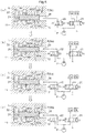
FIG. 5 shows successive changes in the position of a lock member and a lock recess. -
FIG. 6 shows a flowchart of unlocking/phase control. -
FIG. 7 is a timing chart showing the relationship of a lock control valve, a phase control valve, and an internal rotor. - Following is a description of an embodiment of the present disclosure with reference to drawings.
- As shown in
FIG. 1 , a system for controlling valve opening/closing timing is configured having a valve opening/closingtiming control device 10 provided in anintake camshaft 3 of an engine E serving as an internal combustion engine, a phase control valve 21 (one example of a first control valve) that controls a relative rotation phase of the valve opening/closingtiming control device 10, a lock control valve 22 (one example of a second control valve) that controls a lock mechanism L of the valve opening/closing control device 10, and also a control unit 40 (ECU). - The engine E is configured as a four-cycle engine provided in a vehicle such as a passenger vehicle, and the valve opening/closing
timing control device 10 realizes a change in intake timing by changing the rotation phase of acrankshaft 1 and anintake camshaft 3 of the engine E. Thecontrol unit 40 acquires a rotation speed of the engine E, or alternatively, acquires information regarding operation by a driver or the like, and controls the magnetically controlled phase control valve 21 (one example of a first control valve) and the magnetically operated lock control valve 22 (one example of a second control valve). - As shown in
FIGS. 1 to 4 , the valve opening/closingtiming control device 10 is provided with anexternal rotor 11 serving as a drive-side rotary body that rotates synchronously with thecrankshaft 1 of the engine E, and aninternal rotor 12 serving as a driven-side rotary body connected with a connectingbolt 13 to theintake camshaft 3, which opens/closesintake valves 1V of a combustion chamber of the engine E. Theinternal rotor 12 is disposed on the same center axis as a rotational center axis X of theintake camshaft 3, and by containing theinternal rotor 12 within theexternal rotor 11, the respective rotors are capable of relative rotation around the rotational center axis X. - The
external rotor 11 is fastened by a plurality offastening bolts 16 in a state held between afront plate 14 and arear plate 15, and theinternal rotor 12 is disposed between thefront plate 14 and therear plate 15. Atiming sprocket 15S is formed around the outer circumference of therear plate 15. - In the
external rotor 11, a plurality of protrudingportions 11T that protrude to the inside in the radius direction are formed as a single body with theexternal rotor 11, and theinternal rotor 12 is formed in a cylindrical shape having an outer circumference that closely contacts a protruding end of the plurality of protrudingportions 11T. Therefore, at an intermediate position of protrudingportions 11T that are adjacent in the rotation direction, a plurality of fluid pressure chambers C are formed on the outer circumference side of theinternal rotor 12. A plurality ofvanes 17 serving as dividing portions are provided at the outer circumference of theinternal rotor 12. By dividing a fluid pressure chamber C with avane 17, an advance chamber Ca and a retard chamber Cb are formed. - The advance chamber Ca is a space that allows the relative rotation phase to be displaced in an advance direction Sa by supplying a working oil. Conversely, the retard chamber Cb is a space that allows the relative rotation phase to be displaced in a retard direction Sb by supplying the working oil.
- A
timing chain 8 is wrapped around an output sprocket 7 provided in thecrankshaft 1 of the engine E and thetiming sprocket 15S of theexternal rotor 11, and thus theexternal rotor 11 rotates synchronously with thecrankshaft 1. Although not shown in the drawings, a device having a similar configuration as the valve opening/closingtiming control device 10 is also provided at a front end of the camshaft on an exhaust side, and torque is transmitted from thetiming chain 8 to this device as well. - As shown in
FIG. 2 , in the valve opening/closingtiming control device 10, theexternal rotor 11 rotates in a driving rotation direction S due to driving force from thecrankshaft 1. On the other hand, a direction that theinternal rotor 12 rotates relative to theexternal rotor 11 in the same direction as the driving rotation direction S is called an advance direction Sa, and a rotation direction opposite to this direction is called a retard direction Sb. - Also, the relative rotation phase in a state where the
vane 17 has attained the end of operation in the advance direction Sa (including a phase near the end of operation of thevane 17 in the advance direction Sa) is called a most advanced phase, and a relative rotation phase in a state where thevane 17 has attained the end of operation in the retard direction Sb (including a phase near the end of operation of thevane 17 in the retard direction Sb) is called a most retarded phase. - As shown in
FIG. 1 , atorsion spring 18 is provided across theinternal rotor 12 and thefront plate 14, and causes a biasing force to act until, from a state in which the relative rotation phase of theexternal rotor 11 and the internal rotor 12 (referred to below as the relative rotation phase) is in a most retarded state, the relative rotation phase attains an intermediate lock phase P2. - The valve opening/closing
timing control device 10 is provided with a pair of the lock mechanisms L that are capable of holding the rotation phase at a most retarded lock phase P1 (one example of a first lock phase) serving as the most retarded phase as shown inFIG. 4 , and the intermediate lock phase P2 (one example of a second lock phase), which is intermediate between the most advanced phase and the most retarded phase as shown inFIG. 2 . - The respective lock mechanisms L are provided with a pair of
lock members 31 that are supported by theexternal rotor 11 such that a protruding end of thelock members 31 is capable of approaching or separating from the rotational center axis X, and a lock spring 32 (one example of a biasing member) that biases therespective lock members 31 in the protruding direction. A pair of intermediate lock recesses 33 where the pair oflock members 31 independently engage in the intermediate lock phase P2, and a mostretarded lock recess 34 where one of thelock members 31 engages when in the most retarded lock phase P1, are formed in theinternal rotor 12. - Also, the
lock members 31 are configured with plate-like material, and in theexternal rotor 11, are inserted so as to be capable of sliding movement in guide holes 35 formed in a radial shape centered on the rotational center axis X. Theintermediate lock recess 33 and the mostretarded lock recess 34 are formed in a groove-like shape having an attitude parallel to the rotational center axis X. - As shown in
FIGS. 1 to 4 , in the system for controlling valve opening/closing timing, in the engine E, a hydraulic pump P is provided that sucks out oil of an oil pan with driving force of the engine E, and sends this out as the working oil (one example of a fluid), and is provided with a fluid path system that supplies the working oil from the hydraulic pump P to thephase control valve 21 and thelock control valve 22. - Also, an
advance fluid path 24 in communication from thephase control valve 21 to the advance chamber Ca of theinternal rotor 12, and aretard fluid path 25 in communication from thephase control valve 21 to the retard chamber Cb, are formed, and theadvance fluid path 24 is in communication with the mostretarded lock recess 34. Further, anunlock fluid path 26 is formed in communication from thelock control valve 22 to theintermediate lock recess 33 of theinternal rotor 12. - The
phase control valve 21 is configured to be capable of selectively switching between an advance position, a neutral position, and a retard position by adjustment of electrical power supplied to an electromagnetic solenoid of thephase control valve 21. In the advance position, the working oil of the hydraulic pump P is supplied from theadvance fluid path 24 to the advance chamber Ca, and the working oil is discharged from the retard chamber Cb, thereby displacing the relative rotation phase in the advance direction Sa. - Also, in the neutral position, the
phase control valve 21 maintains the relative rotation phase without supplying fluid to or discharging fluid from theadvance fluid path 24 or theretard fluid path 25. In the retard position, the working oil of the hydraulic pump P is supplied from theretard fluid path 25 to the retard chamber Cb, and the working oil is discharged from the advance chamber Ca, thereby displacing the relative rotation phase in the retard direction Sb. The neutral position is positioned between the advance position and the retard position in the movable range of a spool of thephase control valve 21. - The
lock control valve 22 is configured to be capable of operation to a lock position and an unlock position by adjustment of electrical power supplied to an electromagnetic solenoid of thelock control valve 22. In the lock position, the working oil is discharged from theunlock fluid path 26, enabling alock member 31 in the unlock position to shift to a locked state, and maintaining the locked state of alock member 31 that is already in the lock position. - On the other hand, in the unlock position, the working oil is supplied to the
unlock fluid path 26, causing alock member 31 that is in a state engaged into theintermediate lock recess 33 to operate to a position (an ejecting position) disengaging from theintermediate lock recess 33 against the biasing force of thelock spring 32, thereby releasing the locked state. - The
control unit 40 is configured as an ECU, where signals are input from a shaft sensor 1 S, aphase sensor 46, atemperature sensor 47, and apressure sensor 48. The shaft sensor 1S detects the rotation speed and the rotation phase of thecrankshaft 1. Thephase sensor 46 detects the relative rotation phase. Thetemperature sensor 47 detects cooling water temperature (equivalent to oil temperature of the working oil) of the engine E. Thepressure sensor 48 detects the pressure of the working oil discharged from the hydraulic pump P. - In the
control unit 40, software that executes phase control, lock shift control, and unlock control is installed. In the phase control, in a state in which a detection signal from thephase sensor 46 is fed back to thecontrol unit 40, thelock control valve 22 is maintained at the unlock position, and by setting thephase control valve 21 to the advance position or the retard position, the relative rotation phase is displaced in the direction of a target relative rotation phase. - In the lock shift control, when holding the relative rotation phase at the intermediate lock phase P2, the
lock control valve 22 is set to the lock position, and thephase control valve 21 is set to the advance position or the retard position, thereby displacing the relative rotation phase in the direction of the intermediate lock phase P2. When the relative rotation phase detected by thephase sensor 46 by this displacement has been maintained at the intermediate lock phase P2, it is decided that a locked state has been attained. - In an example of the unlock control executed from a state where the lock mechanism L is in a state locked at the intermediate lock phase P2, the
lock control valve 22 is set to the unlock position, and after thelock member 31 has been reliably disengaged from theintermediate lock recess 33, control is performed to shift to the phase control. - The present disclosure is characterized by control to disengage (eject) the
lock member 31 from theintermediate lock recess 33, and that control mode is described below. - When the lock mechanism L is in a state locked at the intermediate lock phase P2, and the working oil is not being supplied to the advance chamber Ca, as shown in
FIG. 5(a) , the relative rotation phase is displaced in the retard direction Sb by a cam average torque T that acts from theintake camshaft 3. Thus, the phase is set to an 'initial phase' in which, as shown inFIG. 5(a) , an end of thelock member 31 contacts one inner wall (afirst wall face 33P) of theintermediate lock recess 33, and an intermediate portion of thelock member 31 contacts one guide face (afirst guide face 35P) of theguide hole 35. - The flowchart in
FIG. 6 shows an overview of 'unlock/phase control' to disengage thelock member 31 in such a contact state from theintermediate lock recess 33, and displace the relative rotation phase. In this control, oil temperature information is acquired from thetemperature sensor 47, oil pressure information of the working oil is acquired from thepressure sensor 48, and based on these items of information, an initial control time period (TP), a first setting time period (T1 and a second setting time period (T2) are set (steps # 01 and #02). - The timing chart in
FIG. 7 shows the relationship between the initial control time period (TP), the first setting time period (T1), and the second setting time period (T2). Also, in the present disclosure, a value (summed value) obtained by adding the first setting time period (T1) and the second setting time period (T2) is an interval used as a period for creating a situation that facilitates release of the locked state of thelock member 31. - The initial control time period (TP), the first setting time period (T1), and the second setting time period (T2) are stored in advance as table data or the like associated with oil temperature information and oil pressure information, and in
step # 02, a processing mode is set such that data stored in advance is read out. Note that a configuration may also be adopted in which the initial control time period (TP), the first setting time period (T1 and the second setting time period (T2) are stored as initial values of predetermined values, and the processing mode is set so as to set the respective time periods by performing a calculation on the initial values, such as multiplying a coefficient based on the temperature information or the pressure information. - In this control, when the oil temperature of the working oil is low and viscosity is high, the speed of displacement of the relative rotation phase in any direction among the advance direction Sa and the retard direction Sb decreases. Also, when the oil temperature of the working oil is high and viscosity is low, the speed of displacement of the relative rotation phase decreases due to leakage of the working oil. Similarly, when the pressure of the working oil discharged from the hydraulic pump P is low, the speed of displacement in a case where the working oil has been supplied to any of the advance chamber Ca and the retard chamber Cb decreases. In order to eliminate such problems, the respective time periods are set in
step # 02. - Next, by setting the
lock control valve 22 to the unlock position, oil pressure is caused to act in theunlock fluid path 26, and thus thephase control valve 21 operates to the advance position for the initial control time period (TP)(steps # 03 and #04). - In
step # 03, first a state is created in which oil pressure is caused to act continuously on thelock member 31 in the unlocking direction. Instep # 04, by operating thephase control valve 21 to the advance position for the initial control time period (TP), the relative rotation phase is displaced in the advance direction Sa by a torque R against the above-described cam average torque T due to pressure of the working oil that acts in the advance chamber Ca, and thus theinternal rotor 12 is set to a 'start phase' shown inFIG. 5(b) . - In the 'start phase', an end of the
lock member 31 is separated from thefirst wall face 33P by the torque R, and this end is caused to contact asecond wall face 33Q at a position opposing thefirst wall face 33P. At the same time, the intermediate portion of thelock member 31 is separated from thefirst guide face 35P, and caused to contact asecond guide face 35Q at a position opposing thefirst guide face 35P. The initial control time period (TP) is set so as to attain this sort of position relationship. - Next, the
phase control valve 21 is operated to the neutral position for the first setting time period (T1), and afterward, thephase control valve 21 is operated to the advance position for the second setting time period (T2)(steps # 05 and #06). - When the
phase control valve 21 has been set to the neutral position by the control instep # 05, the working oil is not supplied to the advance chamber Ca and the retard chamber Cb. Accordingly, displacement of the relative rotation phase in the retard direction Sb is started by the phenomenon of the working oil leaking from the advance chamber Ca, and action of the cam average torque T that acts from theintake camshaft 3. This displacement is performed at a low speed, and by this displacement, thelock member 31 attains a 'return phase' shown inFIG. 5(d) , through the phase shown inFIG. 5(c) . - The first setting time period (T1) is set to a time period shorter than the time period in which the
lock member 31 attains the 'initial phase', and is set such that after the first setting time period (T1) has passed, thelock member 31 attains the 'return phase'. - Afterward, by the control in
step # 06, by setting thephase control valve 21 to the advance position for the second setting time period (T2), the second setting time period (T2) is set such that theinternal rotor 12 is returned to the 'start phase' shown inFIG. 5(b) . - That is, after setting the
internal rotor 12 to the 'start phase' shown inFIG. 5(b) , in a case where the relative rotation phase is displaced in the retard direction Sb by leakage of the working oil and the cam average torque T that acts from theintake camshaft 3, this displacement is caused to be performed at low speed, so thephase control valve 21 is set to the neutral position, and not set to the advance position. - Thus, a state is created in which the
lock member 31 separates from the guide face of theguide hole 35 at the same time as separating from the wall face of theintermediate lock recess 33, so a reduction of resistance that acts on thelock member 31 is realized. Because the resistance that acts on thelock member 31 is reduced in this way, ejection of thelock member 31 from theintermediate lock recess 33 by the oil pressure that acts on thelock member 31 is facilitated. - Also, in this control, the 'return phase' is determined by the first setting time period (T1 but the 'return phase' is not a predetermined phase. Therefore, the interval may also be set such that the 'return phase' shown in
FIG. 5(d) matches the 'initial phase' shown inFIG. 5(a) . - Also, the control to displace the relative rotation phase from the 'start phase' to the 'return phase', and afterward return to the 'start phase', is repeatedly performed until a counter value CT, indicating a number of times of this return, attains a value N that has been set in advance. After this return has been attained N times, the relative rotation phase is displaced by setting the
phase control valve 21 to a position (the advance position or the retard position) corresponding to the target phase (steps #07 to #09). - Next, when the control in
step # 09 has been executed, in a case where displacement of the relative rotation phase in the direction of the target phase could not be confirmed with detection by thephase sensor 46, the first setting time period (T1) and the second setting time period (T2) are extended, and again the control fromstep # 03 onward is repeatedly executed (steps #10 to #12). - Other than the embodiment described above, the present disclosure may also be configured as follows.
- (a) This other embodiment (a) applies to a configuration in which the valve opening/closing
timing control device 10 is provided in an exhaust camshaft. In a valve opening/closingtiming control device 10 provided in an exhaust camshaft, cam average torque from the exhaust camshaft acts in the advance direction Sa. Accordingly, in the 'initial phase', thelock member 31 contacts a wall face/guide face that is opposite to those shown inFIG. 5(a) . Therefore, thephase control valve 21 is set to the retard position in order to shift to the 'start phase', but the control mode of thephase control valve 21 is merely reversed, and the control mode for releasing the locked state of the lock mechanism L can be performed in a manner basically the same as described in the above embodiment.
With the configuration of this other embodiment (a) as well, it is possible to reliably unlock a lock mechanism L of the valve opening/closingtiming control device 10 provided in an exhaust camshaft. - (b) A control mode is set such that the first setting time period (T1) and the second setting time period (T2) are set based on a rotation speed of the engine E detected by the shaft sensor 1S, without using detection results of the
pressure sensor 48. That is, as the rotation speed of the engine E increases, the oil pressure of the working oil discharged from the hydraulic pump P also increases. Accordingly, by adopting such settings, even without providing thepressure sensor 48, it is possible to reflect the oil pressure in the interval, and therefore the configuration also becomes simpler and less expensive. - (c) As the
phase sensor 46, a sensor is used that has properties of being able to detect displacement of an end of thelock member 31 between thefirst wall face 33P and thesecond wall face 33Q of theintermediate lock recess 33. In this configuration, thephase control valve 21 is set to the neutral position, a time period until thephase sensor 46 detects that thelock member 31 has attained displacement from the 'start phase' to the 'return phase' is used as the first setting time period (T1), and a time period until thephase sensor 46 detects that thelock member 31 has attained the 'start phase' is used as the second setting time period (T2). In this control, changing the first setting time period (T1) and the second setting time period (T2) becomes possible by changing the 'return phase'.
Also, in this other embodiment (c), thephase control valve 21 is set to the advance position after thephase sensor 46 has detected that thelock member 31 has attained the 'return phase', and by setting thephase control valve 21 to the advance position, feedback control to set thephase control valve 21 to the neutral position becomes possible after thelock member 31 has attained the 'start phase'. - (d) As the configuration of the lock mechanism L, a configuration may be adopted in which a
single lock member 31 is provided, or a configuration may be adopted in which, for example, thelock member 31 is provided so as to be movable relative to a vane of theinternal rotor 12 in a direction along the rotational center axis X, and theintermediate lock recess 33 is formed in therear plate 15. - (e) A configuration may also be adopted in which, for example, in a case where displacement of the relative rotation phase cannot be confirmed in
step # 10 of the above-described flowchart, and so the initial control time period (TP), the first setting time period (T1), and the second setting time period (T2) are extended, the time periods thus extended are set as initial values and stored in a memory or the like. - By storing initial values that have been extended in this way, based on information acquired afterward from the
temperature sensor 47, thepressure sensor 48, and the like, it is possible to set the initial control time period (TP), the first setting time period (T1), and the second setting time period (T2) to appropriate values. - The present invention is applicable to valve opening/closing timing control devices provided with a lock mechanism causing a lock member to be engaged in or released from a lock recess.
-
- 1:
- crankshaft
- 3:
- camshaft (intake camshaft)
- 10:
- valve opening/closing timing control device
- 11:
- drive-side rotary body (external rotor)
- 12:
- driven-side rotary body (internal rotor)
- 21:
- first control valve (phase control valve)
- 22:
- second control valve (lock control valve)
- 31:
- lock member
- 32:
- biasing member (lock spring)
- 33:
- recess (intermediate lock recess)
- 33P:
- inner wall (first wall face)
- 35:
- guide hole
- 40:
- control unit
- 46:
- phase sensor
- Ca:
- advance chamber
- Cb:
- retard chamber
- E:
- internal combustion engine (engine)
- L:
- lock mechanism
- T:
- cam average torque
Claims (4)
- A system for controlling valve opening/closing timing, comprising:a valve opening/closing timing control device having:a drive-side rotary body that rotates synchronously with a crankshaft of an internal combustion engine;a driven-side rotary body that is contained within the drive-side rotary body, and rotates in unity and coaxially with a camshaft for valve opening/closing; anda lock mechanism that includes a lock member supported slidably in a guide hole of one of the drive-side rotary body and the driven-side rotary body, a recess formed in the other of the drive-side rotary body and the driven-side rotary body, and a biasing member that biases the lock member, the lock mechanism maintaining the drive-side rotary body and the driven-side rotary body in a lock position where the drive-side rotary body and the driven-side rotary body are held at a predetermined relative rotation phase by the lock member engaging in the recess due to biasing force of the biasing member; anda control unit having:a first control valve that selectively switches, among an advance chamber and a retard chamber formed between the drive-side rotary body and the driven-side rotary body, between an advance position where the relative rotation phase is displaced in an advance direction by supply of a fluid to the advance chamber, and a retard position where the relative rotation phase is displaced in a retard direction by supply of the fluid to the retard chamber, and a neutral position where the relative rotation phase is held by stoppage of supply of the fluid to the advance chamber and the retard chamber; anda second control valve switchable from the lock position to an unlock position by the lock member disengaging from the recess, by fluid pressure acting on the lock member in a direction against the biasing force of the biasing member;the control unit executing phase control that changes the relative rotation phase and unlock control that releases a locked state of the lock mechanism by controlling at least any one of the first control valve and the second control valve,wherein the unlock control is executed such that by the second control valve being set to the unlock position, and setting the first control valve to any one of the advance position and the retard position, the lock member contacts an inner wall of the recess based on displacement force in a direction against a cam average torque of the camshaft, and then, by the first control valve being switched to the neutral position, an operation in which the lock member separates from the inner wall due to the cam average torque is performed in a predetermined interval.
- The system for controlling valve opening/closing timing according to claim 1,
wherein the interval is changed according to temperature of the fluid. - The system for controlling valve opening/closing timing according to claims 1 or 2,
wherein the interval is changed according to pressure of the fluid. - The system for controlling valve opening/closing timing according to any one of claims 1 to 3,
comprising a phase sensor that detects the relative rotation phase,
wherein in a case where the phase control is executed after the unlock control was continued for a set time period, and even with execution of this phase control, displacement of the relative rotation phase is not detected by the phase sensor, the interval is set to longer than a predetermined value and then the unlock control is executed again.
Applications Claiming Priority (2)
| Application Number | Priority Date | Filing Date | Title |
|---|---|---|---|
| JP2014056152A JP6201842B2 (en) | 2014-03-19 | 2014-03-19 | Valve timing control system |
| PCT/JP2015/056470 WO2015141475A1 (en) | 2014-03-19 | 2015-03-05 | System for controlling valve opening/closing timing |
Publications (3)
| Publication Number | Publication Date |
|---|---|
| EP3121397A1 true EP3121397A1 (en) | 2017-01-25 |
| EP3121397A4 EP3121397A4 (en) | 2017-04-19 |
| EP3121397B1 EP3121397B1 (en) | 2018-11-28 |
Family
ID=54144449
Family Applications (1)
| Application Number | Title | Priority Date | Filing Date |
|---|---|---|---|
| EP15765886.5A Not-in-force EP3121397B1 (en) | 2014-03-19 | 2015-03-05 | System for controlling valve opening/closing timing |
Country Status (5)
| Country | Link |
|---|---|
| US (1) | US10006320B2 (en) |
| EP (1) | EP3121397B1 (en) |
| JP (1) | JP6201842B2 (en) |
| CN (1) | CN106103918B (en) |
| WO (1) | WO2015141475A1 (en) |
Family Cites Families (16)
| Publication number | Priority date | Publication date | Assignee | Title |
|---|---|---|---|---|
| JP3750936B2 (en) * | 2002-04-25 | 2006-03-01 | 三菱電機株式会社 | Valve timing control device for internal combustion engine |
| JP4161880B2 (en) * | 2003-11-12 | 2008-10-08 | トヨタ自動車株式会社 | Valve timing control device for internal combustion engine |
| US7565888B2 (en) * | 2005-04-22 | 2009-07-28 | Gm Global Technology Operations, Inc. | System to release a stuck lock-pin in a cam phaser |
| JP4600379B2 (en) * | 2006-10-06 | 2010-12-15 | 株式会社デンソー | Valve timing adjustment device |
| US7644692B2 (en) * | 2007-07-05 | 2010-01-12 | Chrysler Group Llc | VVT control method during lock pin disengagement |
| JP5013323B2 (en) | 2008-12-09 | 2012-08-29 | 株式会社デンソー | Variable valve timing control device for internal combustion engine |
| JP4947499B2 (en) | 2009-06-30 | 2012-06-06 | 株式会社デンソー | Variable valve timing control device for internal combustion engine |
| JP5141986B2 (en) * | 2009-07-30 | 2013-02-13 | 株式会社デンソー | Variable valve timing control device for internal combustion engine |
| JP2011038446A (en) | 2009-08-07 | 2011-02-24 | Denso Corp | Valve timing adjusting device |
| US8380423B2 (en) * | 2009-08-27 | 2013-02-19 | GM Global Technology Operations LLC | Diagnostic system and method for hydraulically-actuated cam phasers |
| US8622037B2 (en) * | 2010-05-12 | 2014-01-07 | Delphi Technologies, Inc. | Harmonic drive camshaft phaser with a compact drive sprocket |
| BRPI1010626B1 (en) * | 2010-11-08 | 2020-09-15 | Toyota Jidosha Kabushiki Kaisha | CONTROL DEVICE FOR HYDRAULIC VARIABLE VALVE REGULATION MECHANISM |
| JP2012219767A (en) * | 2011-04-13 | 2012-11-12 | Nippon Soken Inc | Valve timing adjustment device |
| JP5803363B2 (en) * | 2011-07-12 | 2015-11-04 | アイシン精機株式会社 | Valve timing adjustment system |
| US9267398B2 (en) * | 2012-02-29 | 2016-02-23 | Nissan Motor Co., Ltd. | Variable valve timing control device of internal combustion engine |
| JP2013256929A (en) * | 2012-06-14 | 2013-12-26 | Aisin Seiki Co Ltd | Valve open/close timing controller |
-
2014
- 2014-03-19 JP JP2014056152A patent/JP6201842B2/en not_active Expired - Fee Related
-
2015
- 2015-03-05 CN CN201580013089.8A patent/CN106103918B/en not_active Expired - Fee Related
- 2015-03-05 WO PCT/JP2015/056470 patent/WO2015141475A1/en not_active Ceased
- 2015-03-05 US US15/123,943 patent/US10006320B2/en not_active Expired - Fee Related
- 2015-03-05 EP EP15765886.5A patent/EP3121397B1/en not_active Not-in-force
Also Published As
| Publication number | Publication date |
|---|---|
| CN106103918B (en) | 2018-08-07 |
| CN106103918A (en) | 2016-11-09 |
| EP3121397A4 (en) | 2017-04-19 |
| WO2015141475A1 (en) | 2015-09-24 |
| EP3121397B1 (en) | 2018-11-28 |
| JP2015178792A (en) | 2015-10-08 |
| JP6201842B2 (en) | 2017-09-27 |
| US10006320B2 (en) | 2018-06-26 |
| US20170016359A1 (en) | 2017-01-19 |
Similar Documents
| Publication | Publication Date | Title |
|---|---|---|
| US8640663B2 (en) | Oil pressure control apparatus | |
| JP6093134B2 (en) | Valve timing control device for internal combustion engine | |
| EP2863024B1 (en) | Valve timing controller | |
| EP2636858B1 (en) | Variable valve timing control apparatus | |
| JP5916441B2 (en) | Valve timing control device for internal combustion engine | |
| EP2474713A1 (en) | Control device for oil pressure valve variable timing mechanism | |
| US10006320B2 (en) | System for controlling valve opening/closing timing | |
| JPWO2013129110A1 (en) | Variable valve timing control device for internal combustion engine | |
| EP3088692B1 (en) | Control valve | |
| EP3029286A1 (en) | Valve opening/closing timing control device | |
| JP6488915B2 (en) | Valve timing control device | |
| CN103109051A (en) | Variable valve timing apparatus for internal combustion engine | |
| US9945271B2 (en) | Valve opening/closing timing control device | |
| JP6187313B2 (en) | Solenoid valve | |
| EP3179062B1 (en) | Valve opening/closing timing control apparatus | |
| JP2015161341A (en) | solenoid valve | |
| WO2018051778A1 (en) | Valve opening/closing timing control device | |
| JP6589342B2 (en) | Valve timing control device | |
| JP2010169009A (en) | Valve opening/closing timing control device | |
| JP2018184868A (en) | Control valve for valve opening / closing timing control device and valve opening / closing timing control device | |
| JP2018053734A (en) | Valve opening/closing timing control device |
Legal Events
| Date | Code | Title | Description |
|---|---|---|---|
| STAA | Information on the status of an ep patent application or granted ep patent |
Free format text: STATUS: THE INTERNATIONAL PUBLICATION HAS BEEN MADE |
|
| PUAI | Public reference made under article 153(3) epc to a published international application that has entered the european phase |
Free format text: ORIGINAL CODE: 0009012 |
|
| STAA | Information on the status of an ep patent application or granted ep patent |
Free format text: STATUS: REQUEST FOR EXAMINATION WAS MADE |
|
| 17P | Request for examination filed |
Effective date: 20160905 |
|
| AK | Designated contracting states |
Kind code of ref document: A1 Designated state(s): AL AT BE BG CH CY CZ DE DK EE ES FI FR GB GR HR HU IE IS IT LI LT LU LV MC MK MT NL NO PL PT RO RS SE SI SK SM TR |
|
| AX | Request for extension of the european patent |
Extension state: BA ME |
|
| A4 | Supplementary search report drawn up and despatched |
Effective date: 20170317 |
|
| RIC1 | Information provided on ipc code assigned before grant |
Ipc: F01L 1/344 20060101ALI20170313BHEP Ipc: F01L 1/356 20060101AFI20170313BHEP Ipc: F02D 13/02 20060101ALI20170313BHEP Ipc: F01L 1/047 20060101ALI20170313BHEP |
|
| DAV | Request for validation of the european patent (deleted) | ||
| DAX | Request for extension of the european patent (deleted) | ||
| GRAP | Despatch of communication of intention to grant a patent |
Free format text: ORIGINAL CODE: EPIDOSNIGR1 |
|
| STAA | Information on the status of an ep patent application or granted ep patent |
Free format text: STATUS: GRANT OF PATENT IS INTENDED |
|
| INTG | Intention to grant announced |
Effective date: 20180502 |
|
| GRAS | Grant fee paid |
Free format text: ORIGINAL CODE: EPIDOSNIGR3 |
|
| GRAA | (expected) grant |
Free format text: ORIGINAL CODE: 0009210 |
|
| STAA | Information on the status of an ep patent application or granted ep patent |
Free format text: STATUS: THE PATENT HAS BEEN GRANTED |
|
| AK | Designated contracting states |
Kind code of ref document: B1 Designated state(s): AL AT BE BG CH CY CZ DE DK EE ES FI FR GB GR HR HU IE IS IT LI LT LU LV MC MK MT NL NO PL PT RO RS SE SI SK SM TR |
|
| REG | Reference to a national code |
Ref country code: CH Ref legal event code: EP |
|
| REG | Reference to a national code |
Ref country code: AT Ref legal event code: REF Ref document number: 1070502 Country of ref document: AT Kind code of ref document: T Effective date: 20181215 |
|
| REG | Reference to a national code |
Ref country code: DE Ref legal event code: R096 Ref document number: 602015020500 Country of ref document: DE |
|
| REG | Reference to a national code |
Ref country code: IE Ref legal event code: FG4D |
|
| REG | Reference to a national code |
Ref country code: NL Ref legal event code: MP Effective date: 20181128 |
|
| REG | Reference to a national code |
Ref country code: LT Ref legal event code: MG4D |
|
| REG | Reference to a national code |
Ref country code: AT Ref legal event code: MK05 Ref document number: 1070502 Country of ref document: AT Kind code of ref document: T Effective date: 20181128 |
|
| PG25 | Lapsed in a contracting state [announced via postgrant information from national office to epo] |
Ref country code: AT Free format text: LAPSE BECAUSE OF FAILURE TO SUBMIT A TRANSLATION OF THE DESCRIPTION OR TO PAY THE FEE WITHIN THE PRESCRIBED TIME-LIMIT Effective date: 20181128 Ref country code: HR Free format text: LAPSE BECAUSE OF FAILURE TO SUBMIT A TRANSLATION OF THE DESCRIPTION OR TO PAY THE FEE WITHIN THE PRESCRIBED TIME-LIMIT Effective date: 20181128 Ref country code: NO Free format text: LAPSE BECAUSE OF FAILURE TO SUBMIT A TRANSLATION OF THE DESCRIPTION OR TO PAY THE FEE WITHIN THE PRESCRIBED TIME-LIMIT Effective date: 20190228 Ref country code: LV Free format text: LAPSE BECAUSE OF FAILURE TO SUBMIT A TRANSLATION OF THE DESCRIPTION OR TO PAY THE FEE WITHIN THE PRESCRIBED TIME-LIMIT Effective date: 20181128 Ref country code: BG Free format text: LAPSE BECAUSE OF FAILURE TO SUBMIT A TRANSLATION OF THE DESCRIPTION OR TO PAY THE FEE WITHIN THE PRESCRIBED TIME-LIMIT Effective date: 20190228 Ref country code: LT Free format text: LAPSE BECAUSE OF FAILURE TO SUBMIT A TRANSLATION OF THE DESCRIPTION OR TO PAY THE FEE WITHIN THE PRESCRIBED TIME-LIMIT Effective date: 20181128 Ref country code: ES Free format text: LAPSE BECAUSE OF FAILURE TO SUBMIT A TRANSLATION OF THE DESCRIPTION OR TO PAY THE FEE WITHIN THE PRESCRIBED TIME-LIMIT Effective date: 20181128 Ref country code: IS Free format text: LAPSE BECAUSE OF FAILURE TO SUBMIT A TRANSLATION OF THE DESCRIPTION OR TO PAY THE FEE WITHIN THE PRESCRIBED TIME-LIMIT Effective date: 20190328 Ref country code: FI Free format text: LAPSE BECAUSE OF FAILURE TO SUBMIT A TRANSLATION OF THE DESCRIPTION OR TO PAY THE FEE WITHIN THE PRESCRIBED TIME-LIMIT Effective date: 20181128 |
|
| PGFP | Annual fee paid to national office [announced via postgrant information from national office to epo] |
Ref country code: DE Payment date: 20190219 Year of fee payment: 5 |
|
| PG25 | Lapsed in a contracting state [announced via postgrant information from national office to epo] |
Ref country code: GR Free format text: LAPSE BECAUSE OF FAILURE TO SUBMIT A TRANSLATION OF THE DESCRIPTION OR TO PAY THE FEE WITHIN THE PRESCRIBED TIME-LIMIT Effective date: 20190301 Ref country code: SE Free format text: LAPSE BECAUSE OF FAILURE TO SUBMIT A TRANSLATION OF THE DESCRIPTION OR TO PAY THE FEE WITHIN THE PRESCRIBED TIME-LIMIT Effective date: 20181128 Ref country code: RS Free format text: LAPSE BECAUSE OF FAILURE TO SUBMIT A TRANSLATION OF THE DESCRIPTION OR TO PAY THE FEE WITHIN THE PRESCRIBED TIME-LIMIT Effective date: 20181128 Ref country code: PT Free format text: LAPSE BECAUSE OF FAILURE TO SUBMIT A TRANSLATION OF THE DESCRIPTION OR TO PAY THE FEE WITHIN THE PRESCRIBED TIME-LIMIT Effective date: 20190328 Ref country code: AL Free format text: LAPSE BECAUSE OF FAILURE TO SUBMIT A TRANSLATION OF THE DESCRIPTION OR TO PAY THE FEE WITHIN THE PRESCRIBED TIME-LIMIT Effective date: 20181128 |
|
| PGFP | Annual fee paid to national office [announced via postgrant information from national office to epo] |
Ref country code: FR Payment date: 20190213 Year of fee payment: 5 |
|
| PG25 | Lapsed in a contracting state [announced via postgrant information from national office to epo] |
Ref country code: NL Free format text: LAPSE BECAUSE OF FAILURE TO SUBMIT A TRANSLATION OF THE DESCRIPTION OR TO PAY THE FEE WITHIN THE PRESCRIBED TIME-LIMIT Effective date: 20181128 |
|
| PG25 | Lapsed in a contracting state [announced via postgrant information from national office to epo] |
Ref country code: DK Free format text: LAPSE BECAUSE OF FAILURE TO SUBMIT A TRANSLATION OF THE DESCRIPTION OR TO PAY THE FEE WITHIN THE PRESCRIBED TIME-LIMIT Effective date: 20181128 Ref country code: PL Free format text: LAPSE BECAUSE OF FAILURE TO SUBMIT A TRANSLATION OF THE DESCRIPTION OR TO PAY THE FEE WITHIN THE PRESCRIBED TIME-LIMIT Effective date: 20181128 Ref country code: CZ Free format text: LAPSE BECAUSE OF FAILURE TO SUBMIT A TRANSLATION OF THE DESCRIPTION OR TO PAY THE FEE WITHIN THE PRESCRIBED TIME-LIMIT Effective date: 20181128 Ref country code: IT Free format text: LAPSE BECAUSE OF FAILURE TO SUBMIT A TRANSLATION OF THE DESCRIPTION OR TO PAY THE FEE WITHIN THE PRESCRIBED TIME-LIMIT Effective date: 20181128 |
|
| REG | Reference to a national code |
Ref country code: DE Ref legal event code: R097 Ref document number: 602015020500 Country of ref document: DE |
|
| PG25 | Lapsed in a contracting state [announced via postgrant information from national office to epo] |
Ref country code: RO Free format text: LAPSE BECAUSE OF FAILURE TO SUBMIT A TRANSLATION OF THE DESCRIPTION OR TO PAY THE FEE WITHIN THE PRESCRIBED TIME-LIMIT Effective date: 20181128 Ref country code: SK Free format text: LAPSE BECAUSE OF FAILURE TO SUBMIT A TRANSLATION OF THE DESCRIPTION OR TO PAY THE FEE WITHIN THE PRESCRIBED TIME-LIMIT Effective date: 20181128 Ref country code: EE Free format text: LAPSE BECAUSE OF FAILURE TO SUBMIT A TRANSLATION OF THE DESCRIPTION OR TO PAY THE FEE WITHIN THE PRESCRIBED TIME-LIMIT Effective date: 20181128 Ref country code: SM Free format text: LAPSE BECAUSE OF FAILURE TO SUBMIT A TRANSLATION OF THE DESCRIPTION OR TO PAY THE FEE WITHIN THE PRESCRIBED TIME-LIMIT Effective date: 20181128 |
|
| PLBE | No opposition filed within time limit |
Free format text: ORIGINAL CODE: 0009261 |
|
| STAA | Information on the status of an ep patent application or granted ep patent |
Free format text: STATUS: NO OPPOSITION FILED WITHIN TIME LIMIT |
|
| PG25 | Lapsed in a contracting state [announced via postgrant information from national office to epo] |
Ref country code: SI Free format text: LAPSE BECAUSE OF FAILURE TO SUBMIT A TRANSLATION OF THE DESCRIPTION OR TO PAY THE FEE WITHIN THE PRESCRIBED TIME-LIMIT Effective date: 20181128 Ref country code: MC Free format text: LAPSE BECAUSE OF FAILURE TO SUBMIT A TRANSLATION OF THE DESCRIPTION OR TO PAY THE FEE WITHIN THE PRESCRIBED TIME-LIMIT Effective date: 20181128 |
|
| REG | Reference to a national code |
Ref country code: CH Ref legal event code: PL |
|
| 26N | No opposition filed |
Effective date: 20190829 |
|
| GBPC | Gb: european patent ceased through non-payment of renewal fee |
Effective date: 20190305 |
|
| PG25 | Lapsed in a contracting state [announced via postgrant information from national office to epo] |
Ref country code: LU Free format text: LAPSE BECAUSE OF NON-PAYMENT OF DUE FEES Effective date: 20190305 |
|
| REG | Reference to a national code |
Ref country code: BE Ref legal event code: MM Effective date: 20190331 |
|
| PG25 | Lapsed in a contracting state [announced via postgrant information from national office to epo] |
Ref country code: IE Free format text: LAPSE BECAUSE OF NON-PAYMENT OF DUE FEES Effective date: 20190305 Ref country code: LI Free format text: LAPSE BECAUSE OF NON-PAYMENT OF DUE FEES Effective date: 20190331 Ref country code: CH Free format text: LAPSE BECAUSE OF NON-PAYMENT OF DUE FEES Effective date: 20190331 Ref country code: GB Free format text: LAPSE BECAUSE OF NON-PAYMENT OF DUE FEES Effective date: 20190305 |
|
| PG25 | Lapsed in a contracting state [announced via postgrant information from national office to epo] |
Ref country code: BE Free format text: LAPSE BECAUSE OF NON-PAYMENT OF DUE FEES Effective date: 20190331 |
|
| PG25 | Lapsed in a contracting state [announced via postgrant information from national office to epo] |
Ref country code: TR Free format text: LAPSE BECAUSE OF FAILURE TO SUBMIT A TRANSLATION OF THE DESCRIPTION OR TO PAY THE FEE WITHIN THE PRESCRIBED TIME-LIMIT Effective date: 20181128 |
|
| PG25 | Lapsed in a contracting state [announced via postgrant information from national office to epo] |
Ref country code: MT Free format text: LAPSE BECAUSE OF NON-PAYMENT OF DUE FEES Effective date: 20190305 |
|
| REG | Reference to a national code |
Ref country code: DE Ref legal event code: R119 Ref document number: 602015020500 Country of ref document: DE |
|
| PG25 | Lapsed in a contracting state [announced via postgrant information from national office to epo] |
Ref country code: DE Free format text: LAPSE BECAUSE OF NON-PAYMENT OF DUE FEES Effective date: 20201001 |
|
| PG25 | Lapsed in a contracting state [announced via postgrant information from national office to epo] |
Ref country code: CY Free format text: LAPSE BECAUSE OF FAILURE TO SUBMIT A TRANSLATION OF THE DESCRIPTION OR TO PAY THE FEE WITHIN THE PRESCRIBED TIME-LIMIT Effective date: 20181128 |
|
| PG25 | Lapsed in a contracting state [announced via postgrant information from national office to epo] |
Ref country code: HU Free format text: LAPSE BECAUSE OF FAILURE TO SUBMIT A TRANSLATION OF THE DESCRIPTION OR TO PAY THE FEE WITHIN THE PRESCRIBED TIME-LIMIT; INVALID AB INITIO Effective date: 20150305 |
|
| PG25 | Lapsed in a contracting state [announced via postgrant information from national office to epo] |
Ref country code: MK Free format text: LAPSE BECAUSE OF FAILURE TO SUBMIT A TRANSLATION OF THE DESCRIPTION OR TO PAY THE FEE WITHIN THE PRESCRIBED TIME-LIMIT Effective date: 20181128 |
|
| PG25 | Lapsed in a contracting state [announced via postgrant information from national office to epo] |
Ref country code: FR Free format text: LAPSE BECAUSE OF NON-PAYMENT OF DUE FEES Effective date: 20200331 |