EP3121372A1 - Roue de turbine refroidie pour un réacteur - Google Patents
Roue de turbine refroidie pour un réacteur Download PDFInfo
- Publication number
- EP3121372A1 EP3121372A1 EP16176167.1A EP16176167A EP3121372A1 EP 3121372 A1 EP3121372 A1 EP 3121372A1 EP 16176167 A EP16176167 A EP 16176167A EP 3121372 A1 EP3121372 A1 EP 3121372A1
- Authority
- EP
- European Patent Office
- Prior art keywords
- turbine
- inlet
- blade
- cooling
- disc
- Prior art date
- Legal status (The legal status is an assumption and is not a legal conclusion. Google has not performed a legal analysis and makes no representation as to the accuracy of the status listed.)
- Withdrawn
Links
Images


Classifications
-
- F—MECHANICAL ENGINEERING; LIGHTING; HEATING; WEAPONS; BLASTING
- F01—MACHINES OR ENGINES IN GENERAL; ENGINE PLANTS IN GENERAL; STEAM ENGINES
- F01D—NON-POSITIVE DISPLACEMENT MACHINES OR ENGINES, e.g. STEAM TURBINES
- F01D5/00—Blades; Blade-carrying members; Heating, heat-insulating, cooling or antivibration means on the blades or the members
- F01D5/02—Blade-carrying members, e.g. rotors
- F01D5/08—Heating, heat-insulating or cooling means
- F01D5/085—Heating, heat-insulating or cooling means cooling fluid circulating inside the rotor
- F01D5/087—Heating, heat-insulating or cooling means cooling fluid circulating inside the rotor in the radial passages of the rotor disc
-
- F—MECHANICAL ENGINEERING; LIGHTING; HEATING; WEAPONS; BLASTING
- F01—MACHINES OR ENGINES IN GENERAL; ENGINE PLANTS IN GENERAL; STEAM ENGINES
- F01D—NON-POSITIVE DISPLACEMENT MACHINES OR ENGINES, e.g. STEAM TURBINES
- F01D5/00—Blades; Blade-carrying members; Heating, heat-insulating, cooling or antivibration means on the blades or the members
- F01D5/02—Blade-carrying members, e.g. rotors
- F01D5/08—Heating, heat-insulating or cooling means
- F01D5/081—Cooling fluid being directed on the side of the rotor disc or at the roots of the blades
-
- F—MECHANICAL ENGINEERING; LIGHTING; HEATING; WEAPONS; BLASTING
- F01—MACHINES OR ENGINES IN GENERAL; ENGINE PLANTS IN GENERAL; STEAM ENGINES
- F01D—NON-POSITIVE DISPLACEMENT MACHINES OR ENGINES, e.g. STEAM TURBINES
- F01D11/00—Preventing or minimising internal leakage of working-fluid, e.g. between stages
- F01D11/001—Preventing or minimising internal leakage of working-fluid, e.g. between stages for sealing space between stator blade and rotor
-
- F—MECHANICAL ENGINEERING; LIGHTING; HEATING; WEAPONS; BLASTING
- F01—MACHINES OR ENGINES IN GENERAL; ENGINE PLANTS IN GENERAL; STEAM ENGINES
- F01D—NON-POSITIVE DISPLACEMENT MACHINES OR ENGINES, e.g. STEAM TURBINES
- F01D5/00—Blades; Blade-carrying members; Heating, heat-insulating, cooling or antivibration means on the blades or the members
- F01D5/02—Blade-carrying members, e.g. rotors
- F01D5/08—Heating, heat-insulating or cooling means
- F01D5/081—Cooling fluid being directed on the side of the rotor disc or at the roots of the blades
- F01D5/082—Cooling fluid being directed on the side of the rotor disc or at the roots of the blades on the side of the rotor disc
-
- F—MECHANICAL ENGINEERING; LIGHTING; HEATING; WEAPONS; BLASTING
- F01—MACHINES OR ENGINES IN GENERAL; ENGINE PLANTS IN GENERAL; STEAM ENGINES
- F01D—NON-POSITIVE DISPLACEMENT MACHINES OR ENGINES, e.g. STEAM TURBINES
- F01D5/00—Blades; Blade-carrying members; Heating, heat-insulating, cooling or antivibration means on the blades or the members
- F01D5/12—Blades
-
- F—MECHANICAL ENGINEERING; LIGHTING; HEATING; WEAPONS; BLASTING
- F01—MACHINES OR ENGINES IN GENERAL; ENGINE PLANTS IN GENERAL; STEAM ENGINES
- F01D—NON-POSITIVE DISPLACEMENT MACHINES OR ENGINES, e.g. STEAM TURBINES
- F01D5/00—Blades; Blade-carrying members; Heating, heat-insulating, cooling or antivibration means on the blades or the members
- F01D5/30—Fixing blades to rotors; Blade roots ; Blade spacers
- F01D5/3007—Fixing blades to rotors; Blade roots ; Blade spacers of axial insertion type
- F01D5/3015—Fixing blades to rotors; Blade roots ; Blade spacers of axial insertion type with side plates
-
- F—MECHANICAL ENGINEERING; LIGHTING; HEATING; WEAPONS; BLASTING
- F01—MACHINES OR ENGINES IN GENERAL; ENGINE PLANTS IN GENERAL; STEAM ENGINES
- F01D—NON-POSITIVE DISPLACEMENT MACHINES OR ENGINES, e.g. STEAM TURBINES
- F01D9/00—Stators
- F01D9/02—Nozzles; Nozzle boxes; Stator blades; Guide conduits, e.g. individual nozzles
-
- F—MECHANICAL ENGINEERING; LIGHTING; HEATING; WEAPONS; BLASTING
- F05—INDEXING SCHEMES RELATING TO ENGINES OR PUMPS IN VARIOUS SUBCLASSES OF CLASSES F01-F04
- F05D—INDEXING SCHEME FOR ASPECTS RELATING TO NON-POSITIVE-DISPLACEMENT MACHINES OR ENGINES, GAS-TURBINES OR JET-PROPULSION PLANTS
- F05D2220/00—Application
- F05D2220/30—Application in turbines
- F05D2220/32—Application in turbines in gas turbines
- F05D2220/323—Application in turbines in gas turbines for aircraft propulsion, e.g. jet engines
-
- F—MECHANICAL ENGINEERING; LIGHTING; HEATING; WEAPONS; BLASTING
- F05—INDEXING SCHEMES RELATING TO ENGINES OR PUMPS IN VARIOUS SUBCLASSES OF CLASSES F01-F04
- F05D—INDEXING SCHEME FOR ASPECTS RELATING TO NON-POSITIVE-DISPLACEMENT MACHINES OR ENGINES, GAS-TURBINES OR JET-PROPULSION PLANTS
- F05D2250/00—Geometry
- F05D2250/10—Two-dimensional
- F05D2250/18—Two-dimensional patterned
- F05D2250/184—Two-dimensional patterned sinusoidal
-
- F—MECHANICAL ENGINEERING; LIGHTING; HEATING; WEAPONS; BLASTING
- F05—INDEXING SCHEMES RELATING TO ENGINES OR PUMPS IN VARIOUS SUBCLASSES OF CLASSES F01-F04
- F05D—INDEXING SCHEME FOR ASPECTS RELATING TO NON-POSITIVE-DISPLACEMENT MACHINES OR ENGINES, GAS-TURBINES OR JET-PROPULSION PLANTS
- F05D2260/00—Function
- F05D2260/20—Heat transfer, e.g. cooling
-
- Y—GENERAL TAGGING OF NEW TECHNOLOGICAL DEVELOPMENTS; GENERAL TAGGING OF CROSS-SECTIONAL TECHNOLOGIES SPANNING OVER SEVERAL SECTIONS OF THE IPC; TECHNICAL SUBJECTS COVERED BY FORMER USPC CROSS-REFERENCE ART COLLECTIONS [XRACs] AND DIGESTS
- Y02—TECHNOLOGIES OR APPLICATIONS FOR MITIGATION OR ADAPTATION AGAINST CLIMATE CHANGE
- Y02T—CLIMATE CHANGE MITIGATION TECHNOLOGIES RELATED TO TRANSPORTATION
- Y02T50/00—Aeronautics or air transport
- Y02T50/60—Efficient propulsion technologies, e.g. for aircraft
Definitions
- the invention relates to a cooled turbine runner, in particular a medium-pressure or high-pressure turbine runner, for an aircraft engine, in which according to the features of the preamble of claim 1, a cooling device is provided which at least one at least substantially axially and at least over part of the axial length of a Blade foot of a turbine blade extending cooling air supply channel comprises.
- a supply of cooling air passages of the turbine blades is achieved via channels arranged predominantly radially in the interior of the turbine blades.
- the high-pressure blades for cooling secondary air supplied flows from a cavity in front of the turbine wheel by axial channels, which are formed for example between a blade root and a rotor disk and also referred to as bucket groove, from which branch off the radially extending into the blades cooling channels.
- the cooling air supplied here to the cooling air passages of the turbine runner is generally subject to swirling and usually does not occur at an advantageous angle to an inlet in the axial cooling air passages. This results in pressure losses, which severely limit the possibility of cooling the high-pressure turbine blades, for example, as a film cooling. For example, this may result in limiting the performance of the aircraft engine.
- the area of the turbine blade receptacle on the disk rim of the rotor disk of a turbine runner designed so that between a blade root of a turbine blade and a finger disc groove between the disk fingers of the rotor disk, which hold the turbine blade, a slot-likedeluftzu09kanal remains, passed through a cooling air flow in a predominantly axial direction of the turbine blade and branch off from the radial cooling channels into a blade profile of the turbine blade.
- a cooling system for turbine wheels of gas turbine engines with a swirl nozzle ring is known, which is designed in the sense of generating a directed towards the end face of the turbine runner, swirling and circumferentially substantially uninterrupted annular cooling air flow.
- the cooling system has a ring of cooling air receivers, which are formed on the end face of the turbine wheel, which face the swirl nozzle ring and feed cooling channels formed in the turbine rotor blades.
- Thede Kunststoffaufillon are designed as individually to the swirl nozzle ring out of the front of the turbine runner away Pitotrohr sensor.
- An effective cooling of such an embodiment is dependent on the position and orientation of the nozzles of the swirl nozzle ring or the Vorleitdüsen, wherein the supply pressure of the turbine blade with the supplied secondary air if necessary, it is too low and, for example due to a required deflection of the secondary air, high pressure losses can occur in the direction of the secondary air to the airfoil.
- the invention has for its object to form a cooled turbine runner for an aircraft engine of the type described in more detail such that with little effort effective cooling of the turbine blades and the disc rim and thus a long life of the turbine runner regardless of the position and orientation of a Vordralldüse, also Pre-Swirl Nozzle is guaranteed.
- the object is achieved with a trained according to the features of claim 1 turbine wheel.
- a cooled turbine runner for an aircraft engine provided with on a peripheral surface of a rotor disk radially arranged turbine blades, wherein in each case a turbine blade is used with a profiled blade root in a correspondingly profiled Scheibenfingernut on the peripheral surface of the rotor disk, and wherein a cooling device with at least one at least substantially axially and at least over a part of the axial length of the blade root extendingdeluftzu07kanal is provided which has an inlet on an inflow side of the blade root with an inlet opening, wherein the inlet is designed with a projection.
- a central axis of the inlet has an extension component in the direction of rotation of the rotor disk in a direction facing the inlet opening in the region of the inlet opening.
- the turbine wheel according to the invention has the advantage that an efficient turbine blade cooling is achieved by the proposed embodiment of the projection on the input side of the cooling air supply duct, even if there is a cooling air flow whose peripheral component is smaller than that of the rotor.
- This is achieved in that the inlet opening faces through the inventive orientation of the inlet of a cooling air flow and thus also a relative twisted, contrary to the rotational direction of the rotor disc entering through the inlet opening cooling air flow despite spin-pressure losses for a satisfactory cooling of the turbine blades or the Rotation disk is sufficient.
- a projection here means any type of projection or intent, wherein the projection can be embodied both on a separate component and integrally with the turbine blade.
- the projection has, in particular, a greater extension counter to a flow direction of working fluid or secondary air in an annular channel than the disc fingers of the rotor disc in a radial region in which the projection is arranged.
- a turbine blade may have one or more projections in the region of its blade root which are spaced apart in particular in the radial direction.
- the projection is formed on a disk device in the direction of flow upstream of the blade root, which is held in contact, in particular, with the blade root.
- the inlets forming Vorkragungen in a simple manner structurally formable and flexible gestaltbar.
- the disk device can be connected in a variety of ways releasably or permanently to a turbine blade or a plurality of turbine blades and / or the rotor disk.
- the disk device can be designed both as a full ring forming cover plate as well as in the circumferential direction with a plurality of segments, wherein in the latter embodiment, in particular each segment is associated with at least one turbine blade. It can also be provided that a segment is assigned to a plurality of turbine blades, wherein the segments preferably form a particularly complete rotating disc ring in the assembled state.
- the disk device comprises a plurality of inlets associated with a turbine blade.
- any solution disclosed in connection with the invention with a disc device forming a projection with a cooling-air inlet is also advantageous regardless of the orientation of the central axis of the inlet.
- a desired cooling of the turbine blades can be achieved in a simple manner if at least one cooling channel extending from the substantially axial cooling air supply channel branches off at the surface of the turbine blade up to an outlet opening, wherein in particular at least one cooling channel connected to an inlet.
- a turbine blade on three such cooling channels, with fewer or more cooling channels can be provided depending on the application.
- cooling channels can be connected to an inlet.
- a first and a second cooling channel with an inlet and a third cooling channel may be connected to a separate inlet.
- the number of cooling channels combined with an inlet can vary depending on the application.
- a segment of the disk device As an alternative or in addition to an embodiment of a segment of the disk device with a plurality of inlets for a turbine blade, it can also be provided that a segment of the disk device has a plurality of inlets of adjacent turbine blades. As a result, the segments may have a greater extent in the circumferential direction, whereby, for example, a mounting can be facilitated and there is an improved seal.
- the disc device is designed integrally with a sealing device which is arranged in the installed state between adjacent in the axial direction turbine guide and turbine wheels or between stator and rotor devices.
- a sealing device may, for example, constitute a so-called labyrinth seal, a sealing strip on the disk rim or an intermediate stage sealing element.
- mutually facing sides of the disk device and the turbine blade are preferably each made plan, so that they can be brought together in a simple manner in a pressure losses avoiding operative connection.
- the inlet in the region of the projection in the flow direction horizontally has a curvature, wherein a central axis in the region of the inlet of a swirling cooling air flow is at least approximately rectified to thede povertyanströmeuros and is aligned after the curvature substantially in the axial extension of thede povertyzu classroomkanals.
- the curvature of the inlet of the cooling air flow can be configured flat with the upstream side of the turbine blade and the rotor disk, so that the cooling air flow enters the inlet even with a twist with a particularly low pressure drop.
- the cooling air inflow direction can be substantially opposite to the rotation direction of the rotation disk in the relative system in the circumferential direction of the rotor disk.
- the inlet is formed NACA-shaped in the region of the projection, wherein the inlet is limited in the circumferential direction of the turbine wheel in particular by two side surfaces whose distance is opposite to the direction of rotation of the rotor disk in the radial direction increased.
- a flow supplied to the cooling air passage is advantageously disturbed only to a small extent.
- Between the side surfaces of the air inlet can be formed in particular by a ramped running area.
- the inlet can alternatively as in the above-mentioned embodiments in the Art of an inlet scoop or figuratively speaking in the manner of a baseball glove. In each of these inlet shapes, entry losses are minimized.
- the inlet in the region of the projection has a channel cross-sectional surface which widens in a diffuser-like manner in the flow direction, a microcompressor is formed in this case, which advantageously achieves efficient turbine blade cooling with an increase in the static pressure. Also a with a cooling air flow entering the cooling air duct relative to the direction of rotation of the rotor disk is sufficient for satisfactorily cooling the turbine blades despite swirl-induced pressure losses. The
- the geometric design of the micro-compressor is advantageously carried out so that the aerodynamic inlet surface is optimized at the design point to the relative velocity of the flow, and thus a largely lossless inflow into the micro-compressor can be done.
- the slowing down of the flow velocity occurring in the micro-compressor ensures a steady increase in the static pressure, which ultimately leads to an improved cooling system.
- the disk device has, on its side remote from the blade root, a profile connecting the adjacent edges of the inlets, in particular in a wave-like manner, between two circumferentially spaced inlets.
- a wave-like profile can also be used with the blade.
- the profile may be carried out downstream of the edge preferably level-level to the edge having the area or an area between the edges of adjacent inlets may be filled by the profile such that in this area only very little or no turbulence occur. As a result, a pressure loss is avoided, which could lead to reduced cooling.
- the profile can be executed according to the particular application in terms of shape, orientation and location.
- the profile of the upstream surface substantially in the circumferential direction of the turbine device in the region of the inlets, between these and below or above this, extending curved grooves and / or webs, to a flow guide between to improve the inlets to the desired extent.
- the disc means has at least one radially projecting shoulder, by means of which at least one turbine blade is axially secured to the rotor disc, the disc means can also be simply held in its radial position in addition to the axial securing of the turbine blade to the rotor disc.
- a shoulder is provided, by means of which the disc means is halterbar on the rotor disk.
- a shoulder is provided, by means of which the disk device can be brought into engagement with at least one turbine blade.
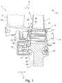
- FIG. 1 to Fig. 3 are different sections and views of a high-pressure or medium-pressure turbine device 1 of an aircraft engine with a Turbinenleitrad 2 and a turbine runner 3 in a first Embodiment apparent.
- the turbine runner 3 has a rotor disk 4, on the disk surface of which formed by a disk rim profiled disk fingers 5 are formed.
- a turbine blade 7 is held with a blade root 8, which has a tannenbaumförmiges profile 9 corresponding to the profiled disc fingers 5.
- a blade neck 10 Radially outward, close to the blade root 8 of the turbine blade 7, a blade neck 10, a blade platform 11, a pressure profile and a suction side exhibiting blade profile 12 and finally an unspecified blade shroud on.
- the turbine blades 7 in the present case are secured by a suitably designed securing device 13, which is held both on the turbine blades 7 and on the rotor disk 4.
- the securing device 13 is in the present case in the radial direction R of the turbine device 1 in several parts from outside to inside viewed with securing segments 41, a sealing element 42 and a snap ring 43 executed.
- a plurality in the present case three cooling ducts 16, 17, 18, acted upon with cooling air, according to a cooling device 15 Fig. 2 which extend starting from the blade root 6 in the radial outward direction and optionally additionally in the transverse direction up to the outlet openings, for example in the form of film cooling bores on the surface of heat-loaded regions of the turbine blade 7.
- the cooling channels 16, 17, 18, in particular the Fig. 8 2 are the cooling channels 16, 17, 18, in particular the Fig. 8 2, in the present case via two cooling air supply channels 20, 21 of the cooling device 15, which extend substantially in the axial direction A of the blade root 8 over a region of the axial length of the blade root 8 and in the radial direction R of the turbine device 1 spaced apart in the blade root. 8 are arranged.
- a radially inner or innerde Kunststoffzu semiconductorkanal 20 is connected to the downstream cooling channel 16
- the radially outer cooling air supply channel 21 is connected to the cooling channels 17 and 18 facing an upstream side 8A of the blade root, in the region of which the highest back pressure exists.
- the turbine runner 1 is a so-called stage II running disk of a second stage of a high-pressure axial turbine of an aircraft engine which, viewed in the flow direction, is arranged in an annular channel 23 according to guide vanes 24 of the turbine nozzle 2.
- the design of the cooling device 15 shown on the turbine runner 1 can basically be used independently of a specific step position.
- cooling air from a Vordralldüse or Pre-Swirl Nozzle 22 of Turbinenleitrads 2 and indicated by arrows 26 cooling air flow and secondary air flow, which is first as a labyrinth seal, which is also referred to as sealing strip or interstage seal element, executed sealing device 14 on Pulley rim of the rotor disk 4 passes, promoted to the guide vanes 24 facing end surface or upstream side 8A of the blade root 8 of the turbine blades 7.
- the cooling flow 26 impinges on the integral integral with the blade root 8 Vorkragept 30, 31, in the axial direction A of the turbine device 1 against a flow direction S of working fluid in the annular channel 23 via the rotor disk 4 in this area by an axial extent 32 and 33rd protrude.
- the pre-projections 30, 31 each have an inlet 34 or 35 with an inlet opening 36 and 37, via the respectivede povertyzu semiconductorkanal 20 and 21, cooling air from the secondary flow fed and from which the cooling air via the radially outwardly branching off the cooling channels 16, 17, 18 is guided to the film cooling holes or outlet openings.
- projections 30, 31 have, in the plan view in the radial direction R of the turbine device 1, one of the blade root geometry the following, due to the fir tree-shaped profile voltage-optimized substantially triangular shape, wherein the projections 30, 31 in the circumferential direction U of the turbine device 1 have a substantially tangential course to the rotor disk 4, so that in this area the smallest possible lossy turbulence occur.
- the cooling air flow toward the cooling air supply ducts 20, 21 has a negative spin with respect to the direction of rotation of the turbine runner 3 shown by the arrow ⁇ .
- a central axis 38 or 40 of the inlets 34 and 35 in the region of the inlet openings 36 and 37 each have an extension component in the direction of rotation ⁇ of the rotor disk 4 and is altogether at an angle ⁇ with respect to the axial direction A of the turbine device 1 is inclined, so that the central axes 38 and 40 in the region of entry of the swirling cooling air flow 26 into the respective inlet 34, 35 at least approximately rectified to the relativedeluftanströmiques, which in the circumferential direction of the rotor disk 4 opposite to the direction of rotation w runs. Losses could be additionally reduced via an advantageous placement of the static pre-whirl nozzle 22.
- the inlets 34, 35 are formed in the region of the projections 30, 31 in such a horizontally curved manner that the center axes 38, 40 are aligned after the curvature substantially along the axial orientation of the blade root 8.
- the inlet openings 36, 37 have a substantially elliptical or oval shape, but can in principle be designed arbitrarily, in particular rounded off.
- the inflow-side edges of the inlet openings 36 may advantageously be formed with a bevel or a radius in terms of flow.
- the length of the axial extensions 32, 33 of the projections 30, 31 can be selected depending on the application, with a small axial extent or length 32, 33 of the projections 30, 31 basically a loss in the form of turbulence is minimized and on the other hand a large axial extension 32, 33 a with respect to the deflection of the cooling air flow 26 optimized design can be achieved. Furthermore, the angle ⁇ is variable depending on the application.
- the projection 30 has a shoulder 39 extending inwards in the radial direction R of the turbine device 1, by means of which a movement of the turbine blade 7 in the axial direction A of the turbine device 1 is prevented.
- an elaborate milling in the area of the rotor disk 4 can advantageously be dispensed with in order to ensure axial securing of the turbine blade 7 against the rotor disk 4.
- the inlets 34, 35 can form a type of microcompressor in the region of the projections 30, 31 by a channel geometry that widens in the direction of flow, such as a diffuser. As in particular in Fig. 3 it can be seen, deflect the Vorkragieux 30 and 31, the cooling air flow 26 guided therein, wherein the cooling air flow slows down and thus the pressure is increased.
- U in the direction of rotation ⁇ may have a relative speed of, for example 200 m / s, experiences in the corresponding aerodynamically designed, expanding in the channel cross-section Vorkragungen an increase in pressure, resulting in a significantdestromstau Kunststoff rest at the exit from the Vorkragung or transition into the axially straight channel region of themé Kunststoffzu technologicalkanals 20, 21 results.
- This additional pressure can be used to cool the turbine blade more efficiently than with conventional systems.
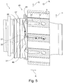
- Fig. 4 and Fig. 5 show an alternative embodiment of a turbine runner 46, wherein in the following only on the differences from the turbine runner 3 according to Fig. 1 to Fig. 3 will be received.
- the turbine runner 46 is designed with a disk device 47 or cover plate which has the inlets 34, 35 with the projections 30, 31 and is designed as a ring that completely revolves in the circumferential direction U of the turbine device 1 and thus as a full ring or "rim cover plate". which is supported radially on the rotor disk 4.
- the disc device 47 also has the intermediate stage sealing element 14 and is held in the region of a groove 48 of the rotor disc 4 at this.
- the inflow side or front side 8A of the blade roots 8 lies substantially in a plane with an inflow side 4A of the rotor disk 4 in this area.
- the disk device 47 and the turbine blades 7 are as in FIG Fig. 5 can be seen in more detail on each side facing each other with their contact surfaces plan.
- a profile 49 of the disk device 47 on a side facing away from the turbine blades 7 is selected such that in this area in the circumferential direction U of the turbine device 1 as low as possible flow losses occur and the cooling air to the inlets 34 and 35 is supplied to the desired extent.
- the profile 49 in the circumferential direction U of the turbine device 1 between adjacent inlets 34 and 35 is executed like a wave.
- grooves 54 or webs 55 may be provided in this area, as exemplified in Fig. 4 is shown. The shape, the orientation and the position of the grooves 54 and webs 55 are variable depending on the requirements.
- turbulences are reduced due to the advantageously large inflow area, with a great design freedom, in particular with respect to the arrangement of the inlets 34, 35 is present.
- a favorable seal between the turbine blades 7 and the rotor disk 4 is achieved by means of the disk device 47, so that a cooling air consumption is reduced via leaks and thus the turbine efficiency is increased.
- the turbine blades 7 can advantageously with less weight compared to the embodiment according to Fig. 1 to Fig. 3 be carried out, whereby a load effect in the area of the blade roots 8 is reduced with consequent advantages for the weight-optimized design and / or the life.
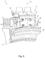
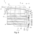
- FIG Fig. 6 to Fig. 8 Another embodiment of a turbine runner 58 is shown in FIG Fig. 6 to Fig. 8 only the differences between the turbine runner 58 and the turbine runner 46 will be described below.
- the turbine wheel 58 in turn has a disk device 59, which, however, is designed to be segmented in several parts in the circumferential direction U of the turbine device 1.
- a segment 60 of the disc device 59 is shown, to which in the mounted state in the circumferential direction U of the turbine device 1 in both directions executed in particular identical and in Fig. 6 Connect unspecified segments 60. All segments 60 form a completely circumferential segmented disc ring in the assembled state.
- the segment 60 as shown Fig. 6 in the circumferential direction U of the turbine device 1, one of the extension of two turbine blades 7 corresponding extent, wherein the segment in an alternative embodiment
- the invention may also have only an extension of a turbine blade, a plurality of turbine blades or intermediate values.
- a support and configuration of the individual segments 60 is selected depending on the existing geometry of the turbine blades 7 and the rotor disk 4, the present loads and leakage requirements.
- a separate component 61 is provided as a "rim cover plate", which may comprise a rotor part of the sealing device 14.
- the segment 60 interacts with the component 61 via a shoulder 64 that faces inward in the radial direction R of the turbine device 1.
- segment 60 according to Fig. 8 an outwardly extending in the radial direction R of the turbine device 1 paragraph 62, via which the segment 60 is mounted in a groove 63 of the turbine blades 7. Securing the segments against rotation relative to the turbine blades or to the rotor disk 4 takes place expediently via a positive connection between the disk and the blade by means of projections and pockets.
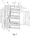
- FIGS. 9 and 10 Another embodiment of a turbine runner 67 is shown in FIGS. 9 and 10 In the following description, substantially the differences from the turbine runner 58 are shown.
- FIGS. 9 and 10 a disk device 69 designed with segments 68 can be seen, wherein the segments 68 in the circumferential direction U of the turbine device 1 extend over two turbine blades 7 in the present case.
- both a blade feet 8 facing as well as a flowed, the blade roots 8 opposite side of the segments 68 is planar executed, wherein the projections 30, 31 are formed with the inlets 34, 35 through the segments 68.
- some inlets 34, 35 are formed on a segment 68 and other inlets 34, 35 on two in the circumferential direction U of the turbine device 1 adjacent segments 68.
- the inlets 34, 35 are here each in the form of a NACA inlet, a so-called NACA inlet duct or "submerged inlet” executed, which is characterized by very low flow losses in the circumferential direction U of the turbine device 1.
- the cooling air 26 is the inlets 34, 35 fed optimized or sucked through this.
- the inlets 34, 35 have, in the side view in the present case, essentially a triangular shape, wherein their flanks 71, 72 can be straight at an angle to one another and / or curved.
- a flank 73 of the inlets 34, 35 which points in the direction of rotation ⁇ , is made essentially straight, so that a ramp-shaped region is thereby formed.
- a further edge 74 counter to the direction of rotation ⁇ is shortened and formed with a radius.
- a cross section of the inlet 34, 35 in a region of the segment 68 adjoining the blade root 8 is smaller than a cross section of the cooling air supply channel 21 in a region adjoining the segment 68, so that there is a sudden cross-sectional widening here.
- Such an abrupt cross-sectional widening can also be used analogously in all of the turbine runners 3, 46 and 58 described above in order to anticipate tolerance-related deviations from the disk device 47, rotor disk 4 and turbine blade 7.
- grooves and / or webs may be provided to make a flow guide to the desired extent.
- the disk device is designed as a solid ring.
Applications Claiming Priority (1)
| Application Number | Priority Date | Filing Date | Title |
|---|---|---|---|
| DE102015111750.9A DE102015111750A1 (de) | 2015-07-20 | 2015-07-20 | Gekühltes Turbinenlaufrad für ein Flugtriebwerk |
Publications (1)
| Publication Number | Publication Date |
|---|---|
| EP3121372A1 true EP3121372A1 (fr) | 2017-01-25 |
Family
ID=56203281
Family Applications (1)
| Application Number | Title | Priority Date | Filing Date |
|---|---|---|---|
| EP16176167.1A Withdrawn EP3121372A1 (fr) | 2015-07-20 | 2016-06-24 | Roue de turbine refroidie pour un réacteur |
Country Status (3)
| Country | Link |
|---|---|
| US (1) | US10196895B2 (fr) |
| EP (1) | EP3121372A1 (fr) |
| DE (1) | DE102015111750A1 (fr) |
Cited By (5)
| Publication number | Priority date | Publication date | Assignee | Title |
|---|---|---|---|---|
| CN109030012A (zh) * | 2018-08-24 | 2018-12-18 | 哈尔滨电气股份有限公司 | 一种带有冷却通道的透平叶根疲劳试验模拟件及试验方法 |
| EP3421171A1 (fr) * | 2017-06-30 | 2019-01-02 | Honeywell International Inc. | Roues de turbine, moteurs de turbine les comprenant et procédés de fabrication de roues de turbine à géométrie de ligne de liaison améliorée |
| WO2020023007A1 (fr) * | 2018-07-23 | 2020-01-30 | Siemens Aktiengesellschaft | Plaque de recouvrement avec inducteur d'écoulement et procédé de refroidissement d'aubes de turbine |
| WO2020023005A1 (fr) * | 2018-07-23 | 2020-01-30 | Siemens Aktiengesellschaft | Plaque de recouvrement avec inducteur d'écoulement et procédé de refroidissement d'aubes de turbine |
| FR3118783A1 (fr) * | 2021-01-14 | 2022-07-15 | Safran Aircraft Engines | Turbine a gaz haute-pression pour turbomachine |
Families Citing this family (13)
| Publication number | Priority date | Publication date | Assignee | Title |
|---|---|---|---|---|
| DE102017109952A1 (de) * | 2017-05-09 | 2018-11-15 | Rolls-Royce Deutschland Ltd & Co Kg | Rotorvorrichtung einer Strömungsmaschine |
| EP3495611B1 (fr) * | 2017-12-06 | 2020-07-29 | Ansaldo Energia Switzerland AG | Appareil d'administration contrôlée d'air de refroidissement pour aubes de turbine dans une turbine à gaz |
| CN108087123A (zh) * | 2018-01-11 | 2018-05-29 | 南京航空航天大学 | 一种用于预旋冷却系统的多排接受孔结构 |
| CN108180076B (zh) * | 2018-01-12 | 2024-04-12 | 南京航空航天大学 | 一种用于冷气预旋的双排喷嘴结构 |
| EP3564489A1 (fr) * | 2018-05-03 | 2019-11-06 | Siemens Aktiengesellschaft | Rotor à surfaces de contact optimisées au niveau de forces centrifuges |
| US10704400B2 (en) * | 2018-10-17 | 2020-07-07 | Pratt & Whitney Canada Corp. | Rotor assembly with rotor disc lip |
| FR3092609B1 (fr) * | 2019-02-12 | 2021-02-12 | Safran Aircraft Engines | Ensemble de turbine pour turbomachine d’aeronef a circuit de refroidissement de disque ameliore |
| FR3101670B1 (fr) * | 2019-10-08 | 2021-10-08 | Safran Aircraft Engines | Injecteur pour une turbine haute pression |
| JP7271408B2 (ja) * | 2019-12-10 | 2023-05-11 | 東芝エネルギーシステムズ株式会社 | タービンロータ |
| DE102020103648A1 (de) * | 2020-02-12 | 2021-08-12 | Doosan Heavy Industries & Construction Co., Ltd. | Pralleinsatz zur Wiederverwendung von Prallluft in einem Schaufelblatt, Schaufelblatt, das einen Pralleinsatz umfasst, Turbomaschinenkomponente und damit versehende Gasturbine |
| IT202000004585A1 (it) * | 2020-03-04 | 2021-09-04 | Nuovo Pignone Tecnologie Srl | Turbina e pala perfezionate per la protezione della radice dai gas caldi del percorso del flusso. |
| GB202114773D0 (en) | 2021-10-15 | 2021-12-01 | Rolls Royce Plc | Bladed disc |
| US11725526B1 (en) | 2022-03-08 | 2023-08-15 | General Electric Company | Turbofan engine having nacelle with non-annular inlet |
Citations (6)
| Publication number | Priority date | Publication date | Assignee | Title |
|---|---|---|---|---|
| DE1221497B (de) * | 1962-05-09 | 1966-07-21 | Rolls Royce | Verdichter- oder Turbinenbaugruppe in einem Gasturbinenaggregat, insbesondere Gasturbinenstrahltriebwerk |
| US4178129A (en) | 1977-02-18 | 1979-12-11 | Rolls-Royce Limited | Gas turbine engine cooling system |
| EP1004748A2 (fr) | 1998-11-27 | 2000-05-31 | Rolls-Royce Deutschland GmbH | Rotor pour une turbomachine |
| DE10332561A1 (de) | 2003-07-11 | 2005-01-27 | Rolls-Royce Deutschland Ltd & Co Kg | Gekühltes Turbinenlaufrad, insbesondere Hochdruckturbinenlaufrad für ein Flugtriebwerk |
| EP1464792B1 (fr) | 2003-03-26 | 2006-07-19 | ROLLS-ROYCE plc | Méthode de refroidissement de l'assemblage en pied de sapin entre un disque de turbine et ses aubes associées |
| US20070116571A1 (en) * | 2004-12-03 | 2007-05-24 | Toufik Djeridane | Rotor assembly with cooling air deflectors and method |
Family Cites Families (5)
| Publication number | Priority date | Publication date | Assignee | Title |
|---|---|---|---|---|
| US4582467A (en) * | 1983-12-22 | 1986-04-15 | United Technologies Corporation | Two stage rotor assembly with improved coolant flow |
| FR2663997B1 (fr) * | 1990-06-27 | 1993-12-24 | Snecma | Dispositif de fixation d'une couronne de revolution sur un disque de turbomachine. |
| EP0626036B1 (fr) * | 1992-02-10 | 1996-10-09 | United Technologies Corporation | Ejecteur ameliore pour fluide refrigerant |
| US5984636A (en) * | 1997-12-17 | 1999-11-16 | Pratt & Whitney Canada Inc. | Cooling arrangement for turbine rotor |
| US7465149B2 (en) * | 2006-03-14 | 2008-12-16 | Rolls-Royce Plc | Turbine engine cooling |
-
2015
- 2015-07-20 DE DE102015111750.9A patent/DE102015111750A1/de not_active Withdrawn
-
2016
- 2016-06-24 EP EP16176167.1A patent/EP3121372A1/fr not_active Withdrawn
- 2016-07-20 US US15/215,145 patent/US10196895B2/en not_active Expired - Fee Related
Patent Citations (6)
| Publication number | Priority date | Publication date | Assignee | Title |
|---|---|---|---|---|
| DE1221497B (de) * | 1962-05-09 | 1966-07-21 | Rolls Royce | Verdichter- oder Turbinenbaugruppe in einem Gasturbinenaggregat, insbesondere Gasturbinenstrahltriebwerk |
| US4178129A (en) | 1977-02-18 | 1979-12-11 | Rolls-Royce Limited | Gas turbine engine cooling system |
| EP1004748A2 (fr) | 1998-11-27 | 2000-05-31 | Rolls-Royce Deutschland GmbH | Rotor pour une turbomachine |
| EP1464792B1 (fr) | 2003-03-26 | 2006-07-19 | ROLLS-ROYCE plc | Méthode de refroidissement de l'assemblage en pied de sapin entre un disque de turbine et ses aubes associées |
| DE10332561A1 (de) | 2003-07-11 | 2005-01-27 | Rolls-Royce Deutschland Ltd & Co Kg | Gekühltes Turbinenlaufrad, insbesondere Hochdruckturbinenlaufrad für ein Flugtriebwerk |
| US20070116571A1 (en) * | 2004-12-03 | 2007-05-24 | Toufik Djeridane | Rotor assembly with cooling air deflectors and method |
Cited By (8)
| Publication number | Priority date | Publication date | Assignee | Title |
|---|---|---|---|---|
| EP3421171A1 (fr) * | 2017-06-30 | 2019-01-02 | Honeywell International Inc. | Roues de turbine, moteurs de turbine les comprenant et procédés de fabrication de roues de turbine à géométrie de ligne de liaison améliorée |
| US10751843B2 (en) | 2017-06-30 | 2020-08-25 | Honeywell International Inc. | Turbine wheels, turbine engines including the same, and methods of fabricating turbine wheels with improved bond line geometry |
| WO2020023007A1 (fr) * | 2018-07-23 | 2020-01-30 | Siemens Aktiengesellschaft | Plaque de recouvrement avec inducteur d'écoulement et procédé de refroidissement d'aubes de turbine |
| WO2020023005A1 (fr) * | 2018-07-23 | 2020-01-30 | Siemens Aktiengesellschaft | Plaque de recouvrement avec inducteur d'écoulement et procédé de refroidissement d'aubes de turbine |
| US11377956B2 (en) | 2018-07-23 | 2022-07-05 | Siemens Energy Global GmbH & Co. KG | Cover plate with flow inducer and method for cooling turbine blades |
| CN109030012A (zh) * | 2018-08-24 | 2018-12-18 | 哈尔滨电气股份有限公司 | 一种带有冷却通道的透平叶根疲劳试验模拟件及试验方法 |
| CN109030012B (zh) * | 2018-08-24 | 2024-01-23 | 哈尔滨电气股份有限公司 | 一种带有冷却通道的透平叶根疲劳试验模拟件及试验方法 |
| FR3118783A1 (fr) * | 2021-01-14 | 2022-07-15 | Safran Aircraft Engines | Turbine a gaz haute-pression pour turbomachine |
Also Published As
| Publication number | Publication date |
|---|---|
| US10196895B2 (en) | 2019-02-05 |
| US20170022818A1 (en) | 2017-01-26 |
| DE102015111750A1 (de) | 2017-01-26 |
Similar Documents
| Publication | Publication Date | Title |
|---|---|---|
| EP3121372A1 (fr) | Roue de turbine refroidie pour un réacteur | |
| EP3121373B1 (fr) | Roue de turbine refroidie, plus particulièrement pour un réacteur | |
| EP3093447B1 (fr) | Rotor d'une turbine a gaz ayant un guidage d'air de refroidissement ameliore | |
| EP3121371B1 (fr) | Turbine comprenant des aubes directrices refroidies | |
| EP2669474B1 (fr) | Canal de passage pour une turbomachine et turbomachine | |
| EP2194232B1 (fr) | Turbomachine dotée d'une barrière à couche frontière sur la paroi latérale | |
| EP1004748B1 (fr) | Roue mobile pour une turbomachine | |
| EP2126321B1 (fr) | Turbine à gaz présentant une couronne directrice et un mélangeur | |
| EP2693120A2 (fr) | Chambre de combustion de turbine à gaz avec orifices d'air de mélange et éléments de guidage d'air de construction modulaire | |
| CH708487A2 (de) | Verfahren und System zum Kühlen von Laufschaufel-Engelsflügeln. | |
| EP2746533B1 (fr) | Grille d'aube et turbomachine | |
| EP3336313A1 (fr) | Ensemble d'aube mobile pour turbines d'une turbine turbine à gaz et procédé de fourniture d'air sceau dans un ensemble d'aube mobile pour turbines | |
| EP3290644B1 (fr) | Turbine à gaz | |
| EP3109410B1 (fr) | Dispositif de stator pour une turbomachine comprenant un dispositif de carter et plusieurs aubes directrices | |
| EP2808556B1 (fr) | Ensemble structurel pour une turbomachine | |
| EP2806103B1 (fr) | Grille d'aubes et turbomachine | |
| EP2818724A1 (fr) | Turbomachine, structure de circulation et procédé | |
| EP3561228B1 (fr) | Aube, segment d'aube et module pour une turbomachine et turbomachine | |
| EP2597257A1 (fr) | Aubage | |
| EP2788583A1 (fr) | Aube directrice de turbine équipée d'un élément d'étranglement | |
| EP2607625A1 (fr) | Turbomachine et étage de turbomachine | |
| EP3159487B1 (fr) | Stator d'une turbine à gaz ayant un guidage d'air de refroidissement amélioré | |
| EP2453109B1 (fr) | Agencement de turbine à gaz et procédé de fonctionnement d'un agencement de turbine à gaz | |
| EP1001138B1 (fr) | Dispositif d'étanchéité pour les extrémités des aubes de turbine | |
| EP3109408A1 (fr) | Dispositif de stator pour une turbomachine comprenant un dispositif de carter et plusieurs aubes directrices |
Legal Events
| Date | Code | Title | Description |
|---|---|---|---|
| PUAI | Public reference made under article 153(3) epc to a published international application that has entered the european phase |
Free format text: ORIGINAL CODE: 0009012 |
|
| AK | Designated contracting states |
Kind code of ref document: A1 Designated state(s): AL AT BE BG CH CY CZ DE DK EE ES FI FR GB GR HR HU IE IS IT LI LT LU LV MC MK MT NL NO PL PT RO RS SE SI SK SM TR |
|
| AX | Request for extension of the european patent |
Extension state: BA ME |
|
| 17P | Request for examination filed |
Effective date: 20170725 |
|
| RBV | Designated contracting states (corrected) |
Designated state(s): AL AT BE BG CH CY CZ DE DK EE ES FI FR GB GR HR HU IE IS IT LI LT LU LV MC MK MT NL NO PL PT RO RS SE SI SK SM TR |
|
| STAA | Information on the status of an ep patent application or granted ep patent |
Free format text: STATUS: THE APPLICATION HAS BEEN WITHDRAWN |
|
| 18W | Application withdrawn |
Effective date: 20200622 |