EP3121312A1 - Yarn cooler - Google Patents
Yarn cooler Download PDFInfo
- Publication number
- EP3121312A1 EP3121312A1 EP16179202.3A EP16179202A EP3121312A1 EP 3121312 A1 EP3121312 A1 EP 3121312A1 EP 16179202 A EP16179202 A EP 16179202A EP 3121312 A1 EP3121312 A1 EP 3121312A1
- Authority
- EP
- European Patent Office
- Prior art keywords
- porous plate
- cooling air
- yarn
- flow
- thickness ratio
- Prior art date
- Legal status (The legal status is an assumption and is not a legal conclusion. Google has not performed a legal analysis and makes no representation as to the accuracy of the status listed.)
- Granted
Links
Images




Classifications
-
- D—TEXTILES; PAPER
- D01—NATURAL OR MAN-MADE THREADS OR FIBRES; SPINNING
- D01D—MECHANICAL METHODS OR APPARATUS IN THE MANUFACTURE OF ARTIFICIAL FILAMENTS, THREADS, FIBRES, BRISTLES OR RIBBONS
- D01D5/00—Formation of filaments, threads, or the like
- D01D5/08—Melt spinning methods
- D01D5/088—Cooling filaments, threads or the like, leaving the spinnerettes
- D01D5/092—Cooling filaments, threads or the like, leaving the spinnerettes in shafts or chimneys
-
- D—TEXTILES; PAPER
- D01—NATURAL OR MAN-MADE THREADS OR FIBRES; SPINNING
- D01D—MECHANICAL METHODS OR APPARATUS IN THE MANUFACTURE OF ARTIFICIAL FILAMENTS, THREADS, FIBRES, BRISTLES OR RIBBONS
- D01D5/00—Formation of filaments, threads, or the like
- D01D5/08—Melt spinning methods
- D01D5/088—Cooling filaments, threads or the like, leaving the spinnerettes
Definitions
- the present invention relates to a yarn cooler configured to cool yarns spun out downward from a spinneret.
- Patent Literature 1 Japanese Unexamined Patent Publication No. 2008-231607
- a buffer chamber in which cooling air flows upward is formed around a cylindrical member structuring a peripheral wall of a yarn running space, and yarns are cooled by the cooling air entering from the buffer chamber to the yarn running space.
- Patent Literature 1 discloses that one or more porous plates (flow adjustment members) are provided in the buffer chamber. Particularly in FIG. 3 (2), there is disclosed a multiple-stage configuration in which a plurality of porous plates are provided.
- Patent Literature 1 totally fails to disclose how the porous plates are designed in terms of their properties in such a multiple-plate configuration where the plurality of porous plates are provided. Further, the above literature merely describes the advantageous effect brought about by the multiple-plate configuration as follows: even though the porosity of the porous plates is somewhat increased, the effect of flow adjustment is substantially equivalent to that in a single-plate configuration where a single porous plate is provided; and thus clogging in the porous plates is prevented. That is to say, the technique of the Patent Literature 1 is not intended to actively improve the effect of flow adjustment by the multiple-plate configuration, as compared to that in the single-plate configuration.
- An object of the present invention is to actively improve the effect of flow adjustment in a yarn cooler including a plurality of porous plates, as compared with the configuration of a single porous plate, and to effectively restrain a time variation in the flow of cooling air entering into a yarn running space.
- the present invention provides a yarn cooler configured to cool a yarn spun out downward from a spinneret, the yarn cooler including: a cooling cylinder provided below the spinneret to be opposed to the spinneret, the cooling cylinder including therein a yarn running space through which the yarn is runnable, an upper peripheral wall of the yarn running space forming a flow adjustment section configured to adjust the flow of cooling air entering into the yarn running space while a lower peripheral wall of the yarn running space forming a impassable section configured to prevent the cooling air from entering into the yarn running space; an accommodation box accommodating the cooling cylinder, to which box the cooling air is supplied through a supply portion provided at a lower portion of the accommodation box; a first porous plate disposed in a supply passage where the cooling air supplied through the supply portion flows upward along the impassable section, the first porous plate being configured to adjust the flow of the cooling air; and a second porous plate disposed above and apart from the first porous plate in the supply passage, the second porous plate disposed above and apart from the first porous
- the flow of the cooling air supplied through the supply portion of the accommodation box is first adjusted by the first porous plate and then adjusted by the second porous plate, and thereafter, the flow of the cooling air enters into the yarn running space through the flow adjustment section of the cooling cylinder.
- the thickness ratio of the first porous plate is not less than 0.7 and not more than 1.6, and it is more preferable that the thickness ratio of the first porous plate is not less than 0.8 and not more than 1.2.
- the directions of the flow of the cooling air having passed through the first porous plate are paralleled to an upward direction more successfully, and this further promotes the uniformity in the directions of the flow and the flow rates of the cooling air having passed through the second porous plate finally.
- the average porosity of the second porous plate is equal to or larger than the average porosity of the first porous plate.
- the pressure loss (fluid resistance) in the second porous plate is larger than the pressure loss in the first porous plate, it is difficult for the cooling air having passed through the first porous plate to smoothly pass through the second porous plate, which may hinder the flow of the cooling air.
- the average porosity of the second porous plate is designed to be equal to or larger than the average porosity of the first porous plate. This limits the pressure loss in the second porous plate to a predetermined value or less, to ensure the smooth flow of the cooling air.
- the distance between the first porous plate and the second porous plate is not less than 20 mm and not more than 80 mm.
- the distance between the first porous plate and the second porous plate is too large, the flow of the cooling air, the directions of which have been adjusted by the first porous plate to be parallel to the upward direction, may be disturbed before reaching the second porous plate. Meanwhile, if the distance between the first porous plate and the second porous plate is too small, the flow of the cooling air passing through the first porous plate is likely to be affected by the second porous plate, and this may cause unsuccessful flow adjustment by the first porous plate.
- the distance between the first porous plate and the second porous plate as being not less than 20 mm and not more than 80 mm, the effect of the flow adjustment brought about by the use of the first porous plate and the second porous plate is reliably improved.
- a plurality of the cooling cylinders are accommodated in the accommodation box.
- the thickness ratio of the second porous plate by designing the thickness ratio of the second porous plate to be smaller than the thickness ratio of the first porous plate, the effect of flow adjustment is actively improved as compared with the configuration of the single porous plate, and the time variation in the flow of the cooling air entering into the yarn running space is effectively restrained.
- FIG. 1 is a partial cross section of a melt spinning device including the yarn cooler of the present invention.
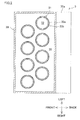
- FIG. 2 is a cross section taken along II-II in FIG. 1 .
- a melt spinning device 1 includes a spinning beam 2, a yarn cooler 3, oiling devices 4, and the like.
- the spinning beam 2 is provided with a plurality of pack housings 11.
- a spinning pack 12 is disposed in each pack housing 11.
- the spinning pack 12 stores therein molten material to be formed into yarns Y, such as molten polyester.
- a spinneret 13 is provided at a lower end portion of each spinning pack 12.
- the molten material stored in the spinning pack 12 is spun out downward as the yarns Y from a plurality of through holes (not illustrated) formed in the spinneret 13.
- the spinnerets 13 are arranged in a staggered arrangement in two rows each extending in a left-right direction, in the same manner as cooling cylinders 31 which will be described later (see FIG. 2 ).
- the yarn cooler 3 is disposed below the spinning beam 2.
- the yarn cooler 3 is configured to cool the yarns Y, which are spun out downward from the spinnerets 13 in the spinning beam 2, by cooling air supplied through a duct 5.
- the oiling devices 4 are disposed below the yarn cooler 3.
- the oiling devices 4 are configured to apply oil to the yarns Y cooled by the yarn cooler 3.
- the yarns Y to which oil has been applied by the oiling devices 4 are wound onto bobbins by an unillustrated winding device which is disposed below the oiling devices 4.
- the yarn cooler 3 is configured to cool the yarns Y by the cooling air supplied through the duct 5.
- the yarn cooler 3 includes a substantially rectangular-parallelepiped accommodation box 30 which accommodates the plurality of cooling cylinders 31.
- the accommodation box 30 is provided with a supply portion 30a at its lower back end portion.
- the supply portion 30a is connected with the duct 5, and the cooling air supplied through the duct 5 flows into the accommodation box 30 via the supply portion 30a.
- the cooling cylinders 31 are arranged in a staggered arrangement in two rows each extending in the left-right direction.
- the staggered arrangement of the cooling cylinders 31 (and the spinnerets 13) enables the cooling cylinders 31 to be arranged densely, to improve the production efficiency of the yarns Y.
- the supply portion 30a is provided to cover the entire length of the accommodation box 30 in the left-right direction, which is a lined-up direction in which the cooling cylinders 31 are lined up in each row. This structure enables the cooling air to be supplied substantially uniformly to the cooling cylinders 31 lined up in the lined up direction.
- Each cooling cylinder 31 has a substantially cylindrical shape, and is disposed below the corresponding spinneret 13 so as to be opposed to the spinneret 13.
- Each cooling cylinder 31 penetrates the accommodation box 30 in an up-down direction.
- the inside of each cooling cylinder 31 is a yarn running space 32 extending in the up-down direction.
- the yarns Y spun out from the spinneret 13 run downward in the yarn running space 32.
- a peripheral wall of the yarn running space 32, i.e., a cylinder body of the cooling cylinder 31 is structured so that its upper portion forms a flow adjustment section 33, while its lower portion forms an impassable section 34.
- the flow adjustment section 33 is structured to include a first flow adjustment member 33a and a second flow adjustment member 33b provided inside the flow adjustment member 33a.
- the first flow adjustment member 33a is formed by perforated metal, for example.
- the first flow adjustment member 33a is configured to adjust the flow so that the flow of the cooling air enters into the yarn running space 32 substantially horizontally.
- the second flow adjustment member 33b is formed by multi-layer metal wire mesh, for example.
- the second flow adjustment member 33b is configured to uniformize the flow of the cooling air entering into the yarn running space 32.
- the impassable section 34 is made of material through which the cooling air is impassable, so that the cooling air does not enter into the yarn running space 32 through the impassable section 34.
- the cooling air entering through the supply portion 30a to the accommodation box 30 flows along the cooling cylinders 31, through a portion of the space in the accommodation box 30 in which portion no cooling cylinder 31 is disposed (this portion is hereinafter referred to as a "supply passage 35"). Finally, the cooling air passes through the flow adjustment section 33 of each cooling cylinder 31 and then enters into the yarn running space 32 (see arrows in FIG. 7 ) . If the cooling air enters into the yarn running space 32 without sufficient flow adjustment, there may be caused a time variation in the flow of the cooling air, possibly leading to unevenness in the yarns Y in terms of cooling.
- a first porous plate 36 and a second porous plate 37 are provided at a portion of the supply passage 35 which is around the impassable sections 34 , i.e., at the portion where the cooling air flows upward along the impassable sections 34.
- the supply passage 35 is actually a single space as shown in FIG. 2 .
- the supply passage 35 is illustrated as if it is divided.
- the reference sign is given to each of the divided parts of the supply passage in FIG. 1 , though the supply passage is a single space. The same applies to FIG. 3 , FIG. 5 , and FIG. 7 .
- the first porous plate 36 is disposed substantially horizontally to be substantially level with an upper end of the supply portion 30a.
- the first porous plate 36 is formed by perforated metal, for example.
- the second porous plate 37 is disposed, not less than 20 mm and not more than 80 mm above the first porous plate 36.
- the second porous plate 37 is disposed substantially horizontally to be substantially level with upper ends of the impassable sections 34.
- the second porous plate 37 is also formed by perforated metal, for example.
- the first and second porous plates 36 and 37 are designed so that the thickness ratio of the second porous plate 37 is smaller than the thickness ratio of the first porous plate 36. This will be detailed later.
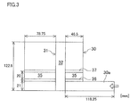
- FIG. 3 is a schematic diagram of an analytical model. The detailed dimensions are indicated in FIG. 3 . Analysis was conducted for 6 cases shown in Table 1 under the condition that: the cooling air enters from the supply portion 30a at a flow rate of 0.437 m 3 /min; and an upper end of the supply passage 35 is open to the atmosphere. Table 1 shows the dispersion in the in-plane velocity of the cooling air having passed through the last porous plate (i.e. , the second porous plate 37 in each of Cases A to E, or the first porous plate 36 in Case F) . Further, FIG.
- porous plate used herein means an average porosity on the entire surface of the porous plate, i.e., the ratio of the total sum of the areas of all the holes to the entire area of the porous plate (the holes may be arranged regularly or irregularly).
- thickness ratio used herein means the ratio of the thickness of the plate to the diameter of the hole.
- the thickness ratio of the second porous plate 37 is smaller than the thickness ratio of the first porous plate 36.
- the thickness ratio of the second porous plate 37 is equal to or larger than the thickness ratio of the first porous plate 36.
- the present inventors arrives at the consideration that: when the thickness ratio of the second porous plate 37 is designed to be smaller than the thickness ratio of the first porous plate 36, the directions of the flow of the cooling air are first paralleled to the upward direction to some extent by the first porous plate 36, and then the flow rates of the cooling air is uniformized by the second porous plate 37, and thereby the effect of the flow adjustment is actively improved.
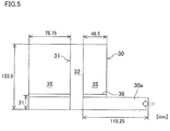
- FIG. 5 is a schematic diagram of an analytical model. The detailed dimensions are indicated in FIG. 5 . Analysis was conducted for 5 cases shown in Table 2 under the condition that: the cooling air enters from the supply portion 30a at a flow rate of 0.437 m 3 /min; and the upper end of the supply passage 35 is open to the atmosphere. Note that how well the directions of the flow of the cooling air are paralleled to the upward direction by the first porous plate 36 is influenced mainly by the thickness ratio, and little by the porosity.
- FIG. 6 is a vector diagram showing the flow of the cooling air obtained through the analysis.
- the thickness ratio is 0.4
- the thickness ratio is 0.7 to 1.6
- the cooling air having passed through the first porous plate 36 flows in the upward direction substantially well, though in some of the cases, the flow of the cooling air having passed through the first porous plate 36 still has a leftward velocity component a little.
- the thickness ratio of the first porous plate 36 is not less than 0.8
- the effect of the flow adjustment was significant.
- the above result shows that when the thickness ratio of the first porous plate 36 is not less than 0.7 (more preferably not less than 0.8) and not more than 1.6, the effect of adjusting the flow of the cooling air to the upward direction by the first porous plate 36 is enhanced, and finally the effect of adjusting the flow of the cooling air having passed through the second porous plate 37 is further enhanced.
- This finding conforms to the fact that among Cases A, D, and E of Table 1 in each of which the effect of the flow adjustment is larger, the dispersion in velocity is significantly reduced particularly in Cases A and E in each of which the thickness ratio of the first porous plate 36 is not less than 0.7 and not more then 1.6.
- FIG. 7 is a cross section schematically showing the flow of the cooling air.
- the flow of the cooling air is schematically illustrated with bold arrows.
- the directions of the flow of the cooling air supplied from the supply portion 30a to the supply passage 35 are substantially paralleled by the first porous plate 36 to the upward direction.
- this effect is particularly significant when the thickness ratio of the first porous plate 36 is not less than 0.7 (more preferably not less than 0.8) and not more than 1.6.
- the porous plates so that the thickness ratio of the second porous plate 37 is smaller than the thickness ratio of the first porous plate 36, the flow rates of the cooling air, the directions of which have been paralleled to the upward direction by the first porous plate 36, are uniformized successfully by the second porous plate 37.
- CV% stands for the coefficient of variation (CV) expressed in percentage, and indicates the degree of dispersion in values of physical properties.
- dispersion in values were obtained, for elongation, strength, U%, and thermal stress of the yarns Y.
- U% is a percentage representing the degree of unevenness in yarns (USTER coefficient) measured using an USTER yarn unevenness tester produced by Zellweger Uster.
- the porous plates so that the thickness ratio of the second porous plate 37 is smaller than the thickness ratio of the first porous plate 36 as is in the present embodiment, uniformity is achieved with respect to the direction of the flow of the cooling air and the flow rate of the cooling air, and thereby the time variation in the flow of the cooling air entering into each yarn running space 32 is effectively restrained. Further, by designing the thickness ratio of the first porous plate 36 to be not less than 0.7 and not more than 1.6, the effect of paralleling the directions of the flow of the cooling air to the upward direction by the first porous plate 36 is improved, and the effect of the flow adjustment as a whole is further improved.
- the upper limit of the thickness ratio of the first porous plate 36 is defined as 1.2, to easily produce the first porous plate 36 and the second porous plate 37 by punch press.
- the thickness ratio of the first porous plate 36 is not less than 0.8, as described above, the effect of the flow adjustment is further improved.
- the thickness ratio of the first porous plate 36 is not less than 0.8 and not more than 1.2.
- the porosity of the second porous plate 37 is equal to or larger than the porosity of the first porous plate 36. If the pressure loss (fluid resistance) in the second porous plate 37 is larger than the pressure loss in the first porous plate 36, it is difficult for the cooling air having passed through the first porous plate 36 to smoothly pass through the second porous plate 37, which may hinder the flow of the cooling air. For this reason, the porosity of the second porous plate 37 is designed to be equal to or larger than the porosity of the first porous plate 36. This prevents the pressure loss in the second porous plate 37 from exceeding a predetermined value, to ensure the smooth flow of the cooling air. This is consistent with the fact that the porosity of the second porous plate 37 is equal to or larger than the porosity of the first porous plate 36 in each of Cases A, D, and E in Table 1, in each of which the effect of the flow adjustment was significant.
- the distance between the first porous plate 36 and the second porous plate 37 is not less than 20 mm and not more than 80 mm. If the distance between the first porous plate 36 and the second porous plate 37 is too large, the flow of the cooling air, the directions of which have been adjusted by the first porous plate 36 to be parallel to the upward direction, may be disturbed before reaching the second porous plate 37. Meanwhile, if the distance between the first porous plate 36 and the second porous plate 37 is too small, the flow of the cooling air passing through the first porous plate 36 is likely to be affected by the second porous plate 37, and this may cause unsuccessful flow adjustment by the first porous plate 36.
- the distance between the first porous plate 36 and the second porous plate 37 as being not less than 20 mm and not more than 80 mm, the effect of the flow adjustment brought about by the use of the first porous plate 36 and the second porous plate 37 is reliably improved.
- the plurality of cooling cylinders 31 are accommodated in the accommodation box 30.
- the plurality of cooling cylinders 31 are disposed in the accommodation box 30, the variation in the flow of the cooling air among the different cooling cylinders 31 tends to be larger because the spaces around the cooling cylinder 31 are different in shape from one another. In this regard, according to the present embodiment, such a variation is able to be decreased well.
- the yarn cooler 3 including the plurality of cooling cylinders 31 disposed in the accommodation box 30, it is not essential that the number of the cooling cylinders 31 in the accommodation box 30 is two or more.
- cooling cylinders 31 are arranged in a staggered arrangement in two rows each extending in the left-right direction in the above-described embodiment, the manner of arrangement of the cooling cylinders 31 is not limited to this.
- the cooling cylinders 31 may be aligned in a single row extending in the left-right direction, or may be arranged in multiple rows in an arrangement manner other than the staggered arrangement.
Landscapes
- Engineering & Computer Science (AREA)
- Mechanical Engineering (AREA)
- Textile Engineering (AREA)
- Spinning Methods And Devices For Manufacturing Artificial Fibers (AREA)
Description
- The present invention relates to a yarn cooler configured to cool yarns spun out downward from a spinneret.
- There have been known yarn coolers each configured to cool yarns spun out from a spinneret, such as a yarn cooler disclosed in Patent Literature 1 (Japanese Unexamined Patent Publication No.
2008-231607 FIG. 3 (2), there is disclosed a multiple-stage configuration in which a plurality of porous plates are provided. - However, Patent Literature 1 totally fails to disclose how the porous plates are designed in terms of their properties in such a multiple-plate configuration where the plurality of porous plates are provided. Further, the above literature merely describes the advantageous effect brought about by the multiple-plate configuration as follows: even though the porosity of the porous plates is somewhat increased, the effect of flow adjustment is substantially equivalent to that in a single-plate configuration where a single porous plate is provided; and thus clogging in the porous plates is prevented. That is to say, the technique of the Patent Literature 1 is not intended to actively improve the effect of flow adjustment by the multiple-plate configuration, as compared to that in the single-plate configuration.
- An object of the present invention is to actively improve the effect of flow adjustment in a yarn cooler including a plurality of porous plates, as compared with the configuration of a single porous plate, and to effectively restrain a time variation in the flow of cooling air entering into a yarn running space.
- To achieve the above obj ect, the present invention provides a yarn cooler configured to cool a yarn spun out downward from a spinneret, the yarn cooler including: a cooling cylinder provided below the spinneret to be opposed to the spinneret, the cooling cylinder including therein a yarn running space through which the yarn is runnable, an upper peripheral wall of the yarn running space forming a flow adjustment section configured to adjust the flow of cooling air entering into the yarn running space while a lower peripheral wall of the yarn running space forming a impassable section configured to prevent the cooling air from entering into the yarn running space; an accommodation box accommodating the cooling cylinder, to which box the cooling air is supplied through a supply portion provided at a lower portion of the accommodation box; a first porous plate disposed in a supply passage where the cooling air supplied through the supply portion flows upward along the impassable section, the first porous plate being configured to adjust the flow of the cooling air; and a second porous plate disposed above and apart from the first porous plate in the supply passage, the second porous plate being configured to further adjust the flow of the cooling air having been adjusted by the first porous plate, wherein the thickness ratio of the second porous plate is smaller than the thickness ratio of the first porous plate.
- In this arrangement, the flow of the cooling air supplied through the supply portion of the accommodation box is first adjusted by the first porous plate and then adjusted by the second porous plate, and thereafter, the flow of the cooling air enters into the yarn running space through the flow adjustment section of the cooling cylinder. By designing the porous plates so that the thickness ratio of the second porous plate is smaller than the thickness ratio of the first porous plate, the directions of the flow of the cooling air and the flow rates of the cooling air are uniformized, and thereby the time variation in the flow of the cooling air entering into the yarn running space is effectively restrained. This will be detailed later.
- Further, in the present invention, it is preferable that the thickness ratio of the first porous plate is not less than 0.7 and not more than 1.6, and it is more preferable that the thickness ratio of the first porous plate is not less than 0.8 and not more than 1.2.
- As will be described later, by designing the thickness ratio of the first porous plate as above, the directions of the flow of the cooling air having passed through the first porous plate are paralleled to an upward direction more successfully, and this further promotes the uniformity in the directions of the flow and the flow rates of the cooling air having passed through the second porous plate finally.
- In addition, it is preferable that the average porosity of the second porous plate is equal to or larger than the average porosity of the first porous plate.
- If the pressure loss (fluid resistance) in the second porous plate is larger than the pressure loss in the first porous plate, it is difficult for the cooling air having passed through the first porous plate to smoothly pass through the second porous plate, which may hinder the flow of the cooling air. For this reason, the average porosity of the second porous plate is designed to be equal to or larger than the average porosity of the first porous plate. This limits the pressure loss in the second porous plate to a predetermined value or less, to ensure the smooth flow of the cooling air.
- Furthermore, it is preferable that the distance between the first porous plate and the second porous plate is not less than 20 mm and not more than 80 mm.
- If the distance between the first porous plate and the second porous plate is too large, the flow of the cooling air, the directions of which have been adjusted by the first porous plate to be parallel to the upward direction, may be disturbed before reaching the second porous plate. Meanwhile, if the distance between the first porous plate and the second porous plate is too small, the flow of the cooling air passing through the first porous plate is likely to be affected by the second porous plate, and this may cause unsuccessful flow adjustment by the first porous plate. Thus, by defining the distance between the first porous plate and the second porous plate as being not less than 20 mm and not more than 80 mm, the effect of the flow adjustment brought about by the use of the first porous plate and the second porous plate is reliably improved.
- Furthermore, it is preferable that a plurality of the cooling cylinders are accommodated in the accommodation box.
- In this arrangement, when sets of yarns are respectively spun out from a plurality of spinnerets, the sets of the yarns are simultaneously cooled in the respective cooling cylinders. When the plurality of cooling cylinders are disposed in the accommodation box, the variation in the flow of the cooling air among the different cooling cylinders tends to be larger because the spaces around the cooling cylinders are different in shape from one another. In this regard, with the present invention, such a variation is able to be decreased well.
- In the present invention, by designing the thickness ratio of the second porous plate to be smaller than the thickness ratio of the first porous plate, the effect of flow adjustment is actively improved as compared with the configuration of the single porous plate, and the time variation in the flow of the cooling air entering into the yarn running space is effectively restrained.
-
-
FIG. 1 is a partial cross section of a melt spinning device including a yarn cooler of the present invention. -
FIG. 2 is a cross section taken along II-II inFIG. 1 . -
FIG. 3 is a schematic diagram of an analytical model. -
FIG. 4 is a vector diagram showing the flow of the cooling air obtained through analysis. -
FIG. 5 is a schematic diagram of an analytical model. -
FIG. 6 is a vector diagram showing the flow of cooling air obtained through analysis. -
FIG. 7 is a cross section schematically showing the flow of the cooling air. - The following will describe an embodiment of a yarn cooler of the present invention.
-
FIG. 1 is a partial cross section of a melt spinning device including the yarn cooler of the present invention.FIG. 2 is a cross section taken along II-II inFIG. 1 . As shown inFIG. 1 , a melt spinning device 1 includes aspinning beam 2, ayarn cooler 3,oiling devices 4, and the like. Thespinning beam 2 is provided with a plurality ofpack housings 11. In eachpack housing 11, aspinning pack 12 is disposed. Thespinning pack 12 stores therein molten material to be formed into yarns Y, such as molten polyester. Aspinneret 13 is provided at a lower end portion of eachspinning pack 12. The molten material stored in thespinning pack 12 is spun out downward as the yarns Y from a plurality of through holes (not illustrated) formed in thespinneret 13. It should be noted that thespinnerets 13 are arranged in a staggered arrangement in two rows each extending in a left-right direction, in the same manner ascooling cylinders 31 which will be described later (seeFIG. 2 ). - The
yarn cooler 3 is disposed below thespinning beam 2. Theyarn cooler 3 is configured to cool the yarns Y, which are spun out downward from thespinnerets 13 in thespinning beam 2, by cooling air supplied through aduct 5. Theoiling devices 4 are disposed below theyarn cooler 3. Theoiling devices 4 are configured to apply oil to the yarns Y cooled by theyarn cooler 3. The yarns Y to which oil has been applied by theoiling devices 4 are wound onto bobbins by an unillustrated winding device which is disposed below theoiling devices 4. - The
yarn cooler 3 is configured to cool the yarns Y by the cooling air supplied through theduct 5. Theyarn cooler 3 includes a substantially rectangular-parallelepiped accommodation box 30 which accommodates the plurality ofcooling cylinders 31. Theaccommodation box 30 is provided with asupply portion 30a at its lower back end portion. Thesupply portion 30a is connected with theduct 5, and the cooling air supplied through theduct 5 flows into theaccommodation box 30 via thesupply portion 30a. - As shown in
FIG. 2 , thecooling cylinders 31 are arranged in a staggered arrangement in two rows each extending in the left-right direction. The staggered arrangement of the cooling cylinders 31 (and the spinnerets 13) enables thecooling cylinders 31 to be arranged densely, to improve the production efficiency of the yarns Y. Thesupply portion 30a is provided to cover the entire length of theaccommodation box 30 in the left-right direction, which is a lined-up direction in which thecooling cylinders 31 are lined up in each row. This structure enables the cooling air to be supplied substantially uniformly to the coolingcylinders 31 lined up in the lined up direction. - Description continues referring back to
FIG. 1 . Each coolingcylinder 31 has a substantially cylindrical shape, and is disposed below the correspondingspinneret 13 so as to be opposed to thespinneret 13. Each coolingcylinder 31 penetrates theaccommodation box 30 in an up-down direction. The inside of each coolingcylinder 31 is ayarn running space 32 extending in the up-down direction. The yarns Y spun out from thespinneret 13 run downward in theyarn running space 32. A peripheral wall of theyarn running space 32, i.e., a cylinder body of thecooling cylinder 31 is structured so that its upper portion forms aflow adjustment section 33, while its lower portion forms animpassable section 34. - The
flow adjustment section 33 is structured to include a firstflow adjustment member 33a and a secondflow adjustment member 33b provided inside theflow adjustment member 33a. The firstflow adjustment member 33a is formed by perforated metal, for example. The firstflow adjustment member 33a is configured to adjust the flow so that the flow of the cooling air enters into theyarn running space 32 substantially horizontally. The secondflow adjustment member 33b is formed by multi-layer metal wire mesh, for example. The secondflow adjustment member 33b is configured to uniformize the flow of the cooling air entering into theyarn running space 32. Theimpassable section 34 is made of material through which the cooling air is impassable, so that the cooling air does not enter into theyarn running space 32 through theimpassable section 34. - The cooling air entering through the
supply portion 30a to theaccommodation box 30 flows along the coolingcylinders 31, through a portion of the space in theaccommodation box 30 in which portion no coolingcylinder 31 is disposed (this portion is hereinafter referred to as a "supply passage 35"). Finally, the cooling air passes through theflow adjustment section 33 of each coolingcylinder 31 and then enters into the yarn running space 32 (see arrows inFIG. 7 ) . If the cooling air enters into theyarn running space 32 without sufficient flow adjustment, there may be caused a time variation in the flow of the cooling air, possibly leading to unevenness in the yarns Y in terms of cooling. In view of the above, in theyarn cooler 3, a firstporous plate 36 and a secondporous plate 37 are provided at a portion of thesupply passage 35 which is around theimpassable sections 34 , i.e., at the portion where the cooling air flows upward along theimpassable sections 34. With this arrangement, the flow adjustment of the cooling air is effectively performed. - It should be noted that the
supply passage 35 is actually a single space as shown inFIG. 2 . In the cross section ofFIG. 1 , thesupply passage 35 is illustrated as if it is divided. For the sake of convenience, the reference sign is given to each of the divided parts of the supply passage inFIG. 1 , though the supply passage is a single space. The same applies toFIG. 3 ,FIG. 5 , andFIG. 7 . - The first
porous plate 36 is disposed substantially horizontally to be substantially level with an upper end of thesupply portion 30a. The firstporous plate 36 is formed by perforated metal, for example. The secondporous plate 37 is disposed, not less than 20 mm and not more than 80 mm above the firstporous plate 36. The secondporous plate 37 is disposed substantially horizontally to be substantially level with upper ends of theimpassable sections 34. Similarly to the firstporous plate 36, the secondporous plate 37 is also formed by perforated metal, for example. In the present embodiment, the first and secondporous plates porous plate 37 is smaller than the thickness ratio of the firstporous plate 36. This will be detailed later. - The present inventors conducted fluid analysis for wholehearted consideration on how the effect of flow adjustment can be improved in the configuration of multiple porous plates.
FIG. 3 is a schematic diagram of an analytical model. The detailed dimensions are indicated inFIG. 3 . Analysis was conducted for 6 cases shown in Table 1 under the condition that: the cooling air enters from thesupply portion 30a at a flow rate of 0.437 m3/min; and an upper end of thesupply passage 35 is open to the atmosphere. Table 1 shows the dispersion in the in-plane velocity of the cooling air having passed through the last porous plate (i.e. , the secondporous plate 37 in each of Cases A to E, or the firstporous plate 36 in Case F) . Further,FIG. 4 is a vector diagram showing the flow of the cooling air obtained through the analysis. Note that "porosity" used herein means an average porosity on the entire surface of the porous plate, i.e., the ratio of the total sum of the areas of all the holes to the entire area of the porous plate (the holes may be arranged regularly or irregularly). Further, "thickness ratio" used herein means the ratio of the thickness of the plate to the diameter of the hole.[Table 1] Case A Case B Case C First porous plate Second porous plate First porous plate Second porous plate First porous plate Second porous plate Plate thickness t [mm] 1.6 0.8 1.6 1.6 0.8 1.6 Hole diameter d [mm] 2 2 2 2 2 2 Thickness ratio t/d [-] 0.8 0.4 0.8 0.8 0.4 0.8 Porosity [%] 29.6 49.7 29.6 29.6 49.7 29.6 Dispersion in in-plane velocity (standard deviation) at 1 mm above the last porous plate 1.91284 3.04940 3.08742 Dispersion in in-plane velocity (standard deviation) at 5 mm above the last porous plate 0.59582 0.97709 1.10766 Dispersion in in-plane velocity (standard deviation) at 10 mm above the last porous plate 0.48911 0.80593 0.91697 Case D Case E Case F First porous plate Second porous plate First porous plate Second porous plate First porous plate Second porous plate Plate thickness t [mm] 0.8 0.4 1.6 0.8 1.6 - Hole diameter d [mm] 2 2 2 2 2 - Thickness ratio t/d [-] 0.4 0.2 0.8 0.4 0.8 - Porosity [%] 29.6 49.7 49.7 49.7 29.6 - Dispersion in in-plane velocity (standard deviation) at 1 mm above the last porous plate 2.04426 1.88220 3.31466 Dispersion in in-plane velocity (standard deviation) at 5 mm above the last porous plate 0.76864 0.61748 1.23981 Variation in in-plane velocity (standard deviation) at 10 mm above the last porous plate 0.66238 0.60356 1.03116 - The dispersion in velocity is improved in each of Cases A to E where both the first
porous plate 36 and the secondporous plate 37 are provided, as compared to Case F where the single porous plate is provided. This shows that the effect of the flow adjustment is improved by providing the plurality of porous plates. However, in Cases B and C, the dispersion in velocity is just a little improved as compared with Case F, and in addition, there were observed relatively larger swirls in the flow of the cooling air having passed through the secondporous plate 37, as can be clearly seen inFIG. 4 . Meanwhile, in Cases A, D, and E, the dispersion in velocity is significantly improved as compared to Case F. Further, no noticeable swirl was found in the flow of the cooling air having passed through the secondporous plate 37 inFIG. 4 . - Among Cases A, D, and E, in which the improvement is larger, there is a common condition: the thickness ratio of the second
porous plate 37 is smaller than the thickness ratio of the firstporous plate 36. Meanwhile, in Cases B and C in which the improvement is smaller, the thickness ratio of the secondporous plate 37 is equal to or larger than the thickness ratio of the firstporous plate 36. Based on the above finding, the present inventors arrives at the consideration that: when the thickness ratio of the secondporous plate 37 is designed to be smaller than the thickness ratio of the firstporous plate 36, the directions of the flow of the cooling air are first paralleled to the upward direction to some extent by the firstporous plate 36, and then the flow rates of the cooling air is uniformized by the secondporous plate 37, and thereby the effect of the flow adjustment is actively improved. - The present inventors further examined an optimum range of the thickness ratio of the first
porous plate 36 through fluid analysis, in order to improve the effect of paralleling the directions of the flow of the cooling air to the upward direction by the firstporous plate 36.FIG. 5 is a schematic diagram of an analytical model. The detailed dimensions are indicated inFIG. 5 . Analysis was conducted for 5 cases shown in Table 2 under the condition that: the cooling air enters from thesupply portion 30a at a flow rate of 0.437 m3/min; and the upper end of thesupply passage 35 is open to the atmosphere. Note that how well the directions of the flow of the cooling air are paralleled to the upward direction by the firstporous plate 36 is influenced mainly by the thickness ratio, and little by the porosity.[Table 2] Case 1 Case 2Case 3Case 4Case 5Plate thickness t [mm] 0.8 1.4 1.6 2.3 3.2 Hole diameter d [mm] 2 2 2 2 2 Thickness ratio t/d [-] 0.4 0.7 0.8 1.15 1.6 Porosity [%] 29.6 29.6 29.6 29.6 29.6 -
FIG. 6 is a vector diagram showing the flow of the cooling air obtained through the analysis. In Case 1 (the thickness ratio is 0.4), the flow of the cooling air, which has flowed from the right to the left in this figure and passed through the firstporous plate 36, still considerably has a leftward velocity component. That is, the effect of paralleling the directions of the flow of the cooling air to the upward direction is relatively smaller. Meanwhile, inCases 2 to 5 (the thickness ratio is 0.7 to 1.6), the cooling air having passed through the firstporous plate 36 flows in the upward direction substantially well, though in some of the cases, the flow of the cooling air having passed through the firstporous plate 36 still has a leftward velocity component a little. Particularly inCases 3 to 5 where the thickness ratio of the firstporous plate 36 is not less than 0.8, the effect of the flow adjustment was significant. - The above result shows that when the thickness ratio of the first
porous plate 36 is not less than 0.7 (more preferably not less than 0.8) and not more than 1.6, the effect of adjusting the flow of the cooling air to the upward direction by the firstporous plate 36 is enhanced, and finally the effect of adjusting the flow of the cooling air having passed through the secondporous plate 37 is further enhanced. This finding conforms to the fact that among Cases A, D, and E of Table 1 in each of which the effect of the flow adjustment is larger, the dispersion in velocity is significantly reduced particularly in Cases A and E in each of which the thickness ratio of the firstporous plate 36 is not less than 0.7 and not more then 1.6. -
FIG. 7 is a cross section schematically showing the flow of the cooling air. The flow of the cooling air is schematically illustrated with bold arrows. First, the directions of the flow of the cooling air supplied from thesupply portion 30a to thesupply passage 35 are substantially paralleled by the firstporous plate 36 to the upward direction. As described above, this effect is particularly significant when the thickness ratio of the firstporous plate 36 is not less than 0.7 (more preferably not less than 0.8) and not more than 1.6. Further, by designing the porous plates so that the thickness ratio of the secondporous plate 37 is smaller than the thickness ratio of the firstporous plate 36, the flow rates of the cooling air, the directions of which have been paralleled to the upward direction by the firstporous plate 36, are uniformized successfully by the secondporous plate 37. As a result, uniformity is achieved with respect to both the direction and flow rate of the cooling air having passed through the secondporous plate 37, and this restrains the time variation in the flow of the cooling air entering into theyarn running space 32. Consequently, unevenness in the yarns Y in terms of cooling is restrained, and the yarns Y having good quality are provided. - Finally, the inventors examined how much the physical properties of the yarns Y are actually improved, as compared with the configuration of the single porous plate, when the porous plates are provided and designed so that the thickness ratio of the second
porous plate 37 is smaller than the thickness ratio of the firstporous plate 36. Table 3 shows its result. It should be noted that CV% stands for the coefficient of variation (CV) expressed in percentage, and indicates the degree of dispersion in values of physical properties. In this test, dispersion in values were obtained, for elongation, strength, U%, and thermal stress of the yarns Y. Note that U% is a percentage representing the degree of unevenness in yarns (USTER coefficient) measured using an USTER yarn unevenness tester produced by Zellweger Uster.[Table 3] Single porous plate Two porous plates First porous plate Second porous plate First porous plate Second porous plate Plate thickness t [mm] 1.6 - 1.6 1 Hole diameter d [mm] 2 - 2 2 Thickness ratio t/d [-] 0.8 - 0.8 0.5 Porosity [%] 29.6 - 29.6 29.6 Strength CV% 3.12 2.06 Elongation CV% 3.16 1.93 U% CVm (hi) 0.41 0.32 Thermal stress CV% 1.72 1.57 - As shown in Table 3, by designing the porous plates so that the thickness ratio of the second
porous plate 37 is smaller than the thickness ratio of the firstporous plate 36, the dispersion in each physical property of the yarns Y is decreased, and the quality of the yarns Y is improved. This confirms that, by improving the effect of the flow adjustment of the cooling air by the firstporous plate 36 and the secondporous plate 37, the time variation in the flow of the cooling air entering into eachyarn running space 32 is restrained, and finally the quality of the yarns Y is reliably improved. - By designing the porous plates so that the thickness ratio of the second
porous plate 37 is smaller than the thickness ratio of the firstporous plate 36 as is in the present embodiment, uniformity is achieved with respect to the direction of the flow of the cooling air and the flow rate of the cooling air, and thereby the time variation in the flow of the cooling air entering into eachyarn running space 32 is effectively restrained. Further, by designing the thickness ratio of the firstporous plate 36 to be not less than 0.7 and not more than 1.6, the effect of paralleling the directions of the flow of the cooling air to the upward direction by the firstporous plate 36 is improved, and the effect of the flow adjustment as a whole is further improved. - As a porous plate, perforated metal, which is a metal plate processed through punch press, is often used. For this reason, if the thickness ratio (thickness) of the porous plate is too large, the punch press process is difficult, and there is a possibility that the intended porous plate cannot be prepared. Thus, in the present embodiment, the upper limit of the thickness ratio of the first
porous plate 36 is defined as 1.2, to easily produce the firstporous plate 36 and the secondporous plate 37 by punch press. In addition, by designing the thickness ratio of the firstporous plate 36 to be not less than 0.8, as described above, the effect of the flow adjustment is further improved. Thus, it is more preferable that the thickness ratio of the firstporous plate 36 is not less than 0.8 and not more than 1.2. - Further, in the present embodiment, it is preferable that the porosity of the second
porous plate 37 is equal to or larger than the porosity of the firstporous plate 36. If the pressure loss (fluid resistance) in the secondporous plate 37 is larger than the pressure loss in the firstporous plate 36, it is difficult for the cooling air having passed through the firstporous plate 36 to smoothly pass through the secondporous plate 37, which may hinder the flow of the cooling air. For this reason, the porosity of the secondporous plate 37 is designed to be equal to or larger than the porosity of the firstporous plate 36. This prevents the pressure loss in the secondporous plate 37 from exceeding a predetermined value, to ensure the smooth flow of the cooling air. This is consistent with the fact that the porosity of the secondporous plate 37 is equal to or larger than the porosity of the firstporous plate 36 in each of Cases A, D, and E in Table 1, in each of which the effect of the flow adjustment was significant. - Furthermore, as is in the present embodiment, it is preferable that the distance between the first
porous plate 36 and the secondporous plate 37 is not less than 20 mm and not more than 80 mm. If the distance between the firstporous plate 36 and the secondporous plate 37 is too large, the flow of the cooling air, the directions of which have been adjusted by the firstporous plate 36 to be parallel to the upward direction, may be disturbed before reaching the secondporous plate 37. Meanwhile, if the distance between the firstporous plate 36 and the secondporous plate 37 is too small, the flow of the cooling air passing through the firstporous plate 36 is likely to be affected by the secondporous plate 37, and this may cause unsuccessful flow adjustment by the firstporous plate 36. Thus, by defining the distance between the firstporous plate 36 and the secondporous plate 37 as being not less than 20 mm and not more than 80 mm, the effect of the flow adjustment brought about by the use of the firstporous plate 36 and the secondporous plate 37 is reliably improved. - Moreover, as is in the present embodiment, it is preferable that the plurality of cooling
cylinders 31 are accommodated in theaccommodation box 30. In this arrangement, when sets of yarns Y are respectively spun out from thespinnerets 13, the sets of the yarns Y are simultaneously cooled in therespective cooling cylinders 31. When the plurality of coolingcylinders 31 are disposed in theaccommodation box 30, the variation in the flow of the cooling air among thedifferent cooling cylinders 31 tends to be larger because the spaces around the coolingcylinder 31 are different in shape from one another. In this regard, according to the present embodiment, such a variation is able to be decreased well. - The present invention is not limited to the embodiment above. Combinations of components of the above embodiment, and various modifications and variations are possible within the scope of the spirit of the invention.
- For example, while the above-described embodiment describes the
yarn cooler 3 including the plurality of coolingcylinders 31 disposed in theaccommodation box 30, it is not essential that the number of the coolingcylinders 31 in theaccommodation box 30 is two or more. - Further, while the cooling
cylinders 31 are arranged in a staggered arrangement in two rows each extending in the left-right direction in the above-described embodiment, the manner of arrangement of the coolingcylinders 31 is not limited to this. For example, the coolingcylinders 31 may be aligned in a single row extending in the left-right direction, or may be arranged in multiple rows in an arrangement manner other than the staggered arrangement.
Claims (6)
- A yarn cooler conf igured to cool a yarn spun out downward from a spinneret, the yarn cooler comprising:a cooling cylinder provided below the spinneret to be opposed to the spinneret, the cooling cylinder including therein a yarn running space through which the yarn is runnable, an upper peripheral wall of the yarn running space forming a flow adjustment section configured to adjust the flow of cooling air entering into the yarn running space while a lower peripheral wall of the yarn running space forming a impassable section configured to prevent the cooling air from entering into the yarn running space;an accommodation box accommodating the cooling cylinder, to which box the cooling air is supplied through a supply portion provided at a lower portion of the accommodation box;a first porous plate disposed in a supply passage where the cooling air supplied through the supply portion flows upward along the impassable section, the first porous plate being configured to adjust the flow of the cooling air; anda second porous plate disposed above and apart from the first porous plate in the supply passage, the second porous plate being configured to further adjust the flow of the cooling air having been adjusted by the first porous plate,wherein the thickness ratio of the second porous plate is smaller than the thickness ratio of the first porous plate.
- The yarn cooler according to claim 1, wherein the thickness ratio of the first porous plate is not less than 0.7 and not more than 1.6.
- The yarn cooler according to claim 2, wherein the thickness ratio of the first porous plate is not less than 0.8 and not more than 1.2.
- The yarn cooler according to any one of claims 1 to 3, wherein the average porosity of the second porous plate is equal to or larger than the average porosity of the first porous plate.
- The yarn cooler according to any one of claims 1 to 4, wherein the distance between the first porous plate and the second porous plate is not less than 20 mm and not more than 80 mm.
- The yarn cooler according to any one of claims 1 to 5, wherein a plurality of the cooling cylinders are accommodated in the accommodation box.
Applications Claiming Priority (1)
| Application Number | Priority Date | Filing Date | Title |
|---|---|---|---|
| JP2015145163A JP6522452B2 (en) | 2015-07-22 | 2015-07-22 | Thread cooler |
Publications (2)
| Publication Number | Publication Date |
|---|---|
| EP3121312A1 true EP3121312A1 (en) | 2017-01-25 |
| EP3121312B1 EP3121312B1 (en) | 2017-07-12 |
Family
ID=56418389
Family Applications (1)
| Application Number | Title | Priority Date | Filing Date |
|---|---|---|---|
| EP16179202.3A Active EP3121312B1 (en) | 2015-07-22 | 2016-07-13 | Yarn cooler |
Country Status (3)
| Country | Link |
|---|---|
| EP (1) | EP3121312B1 (en) |
| JP (1) | JP6522452B2 (en) |
| CN (1) | CN106367821B (en) |
Families Citing this family (2)
| Publication number | Priority date | Publication date | Assignee | Title |
|---|---|---|---|---|
| CN112941646A (en) * | 2021-01-27 | 2021-06-11 | 福建永荣锦江股份有限公司 | Spinning window dust removal cooling device convenient to clearance |
| CN117265676B (en) * | 2022-08-04 | 2025-09-16 | 南通文凯化纤有限公司 | Forming device for graphene filament fibers |
Citations (4)
| Publication number | Priority date | Publication date | Assignee | Title |
|---|---|---|---|---|
| EP0131788A2 (en) * | 1983-07-19 | 1985-01-23 | AlliedSignal Inc. | Filament quenching apparatus |
| JP2008231607A (en) | 2007-03-20 | 2008-10-02 | Toray Ind Inc | Annular cooling device for spinning and melt spinning method |
| CN102199797A (en) * | 2011-06-15 | 2011-09-28 | 大连合成纤维研究设计院股份有限公司 | New spinning side blowing device |
| EP2392698A1 (en) * | 2010-06-04 | 2011-12-07 | TMT Machinery, Inc. | Filament cooler |
Family Cites Families (10)
| Publication number | Priority date | Publication date | Assignee | Title |
|---|---|---|---|---|
| US2399258A (en) * | 1943-03-20 | 1946-04-30 | American Viscose Corp | Novel filamentous product and method of making it |
| BE544451A (en) * | 1955-01-17 | |||
| CN2063527U (en) * | 1990-03-05 | 1990-10-10 | 宋建昌 | Nitrogen-filled slow cooling device |
| JPH06136608A (en) * | 1992-10-28 | 1994-05-17 | Toyobo Co Ltd | Spinning quench device |
| CN2559659Y (en) * | 2002-05-24 | 2003-07-09 | 邓远祥 | Gradient ring blowing commutator |
| JP3868404B2 (en) * | 2003-07-24 | 2007-01-17 | Tmtマシナリー株式会社 | Melt spinning equipment |
| CN100549249C (en) * | 2007-04-23 | 2009-10-14 | 无锡市太极实业股份有限公司 | Cooling device for one-step production of high modulus ultra-low shrinkage polyester industrial yarn |
| JP5452243B2 (en) * | 2010-01-19 | 2014-03-26 | Tmtマシナリー株式会社 | Spin pack for melt spinning equipment |
| JP6069019B2 (en) * | 2013-02-19 | 2017-01-25 | Tmtマシナリー株式会社 | Yarn cooling device |
| JP2015014071A (en) * | 2013-07-08 | 2015-01-22 | Tmtマシナリー株式会社 | Yarn cooling device |
-
2015
- 2015-07-22 JP JP2015145163A patent/JP6522452B2/en active Active
-
2016
- 2016-07-13 EP EP16179202.3A patent/EP3121312B1/en active Active
- 2016-07-14 CN CN201610554810.0A patent/CN106367821B/en active Active
Patent Citations (4)
| Publication number | Priority date | Publication date | Assignee | Title |
|---|---|---|---|---|
| EP0131788A2 (en) * | 1983-07-19 | 1985-01-23 | AlliedSignal Inc. | Filament quenching apparatus |
| JP2008231607A (en) | 2007-03-20 | 2008-10-02 | Toray Ind Inc | Annular cooling device for spinning and melt spinning method |
| EP2392698A1 (en) * | 2010-06-04 | 2011-12-07 | TMT Machinery, Inc. | Filament cooler |
| CN102199797A (en) * | 2011-06-15 | 2011-09-28 | 大连合成纤维研究设计院股份有限公司 | New spinning side blowing device |
Also Published As
| Publication number | Publication date |
|---|---|
| JP6522452B2 (en) | 2019-05-29 |
| EP3121312B1 (en) | 2017-07-12 |
| JP2017025434A (en) | 2017-02-02 |
| CN106367821B (en) | 2020-03-20 |
| CN106367821A (en) | 2017-02-01 |
Similar Documents
| Publication | Publication Date | Title |
|---|---|---|
| EP2899303B1 (en) | Polyphenylene sulfide composite fiber and non-woven fabric | |
| EP3121312B1 (en) | Yarn cooler | |
| EP3492634A1 (en) | Melt spinning device | |
| JP5596422B2 (en) | Yarn cooling device | |
| EP3778999A1 (en) | Method for manufacturing acrylonitrilic fiber bundle and method for manufacturing carbon fiber bundle | |
| DE102014202934B4 (en) | Yarn cooling device | |
| KR101576341B1 (en) | Pressurized steam processing device for thread and production method for carbon fiber precursor thread | |
| DE102014201298A1 (en) | Cradle of spun thread | |
| JP2015014071A (en) | Yarn cooling device | |
| DE102020109250A1 (en) | Process for melt spinning and cooling a wide variety of synthetic filaments | |
| EP3690086A1 (en) | Melt spinning apparatus and non-woven fabric production method | |
| EP3208367B1 (en) | Yarn cooler | |
| JP5585469B2 (en) | Synthetic fiber melt spinning equipment | |
| CN121275476A (en) | Performance detection system for chemical fiber fabric production | |
| EP3012354B1 (en) | Yarn cooler | |
| CN104321641B (en) | Pinhole inspection machine | |
| JP5925657B2 (en) | Melt spinning equipment | |
| KR102705003B1 (en) | Meltblown nonwoven fabric for liquid filter, laminate of said meltblown nonwoven fabric, and liquid filter comprising the laminate | |
| KR101323900B1 (en) | Spinning pack having an excellent indexes of evenness and the method for manufacturing the yarn using the same | |
| EP3441507B1 (en) | Yarn cooler | |
| KR20200020683A (en) | Manufacturing method for spinning packs and fibers | |
| RU2786924C1 (en) | Spinneret pack, method for heating of spinneret pack and process of production of lyocell | |
| US11530494B2 (en) | Spinneret and method for manufacturing fiber web | |
| CN101525773B (en) | Pre-network device for polyamide composite filaments | |
| JP2008007874A (en) | Polyester fiber melt spinning equipment |
Legal Events
| Date | Code | Title | Description |
|---|---|---|---|
| PUAI | Public reference made under article 153(3) epc to a published international application that has entered the european phase |
Free format text: ORIGINAL CODE: 0009012 |
|
| AK | Designated contracting states |
Kind code of ref document: A1 Designated state(s): AL AT BE BG CH CY CZ DE DK EE ES FI FR GB GR HR HU IE IS IT LI LT LU LV MC MK MT NL NO PL PT RO RS SE SI SK SM TR |
|
| AX | Request for extension of the european patent |
Extension state: BA ME |
|
| 17P | Request for examination filed |
Effective date: 20170308 |
|
| RBV | Designated contracting states (corrected) |
Designated state(s): AL AT BE BG CH CY CZ DE DK EE ES FI FR GB GR HR HU IE IS IT LI LT LU LV MC MK MT NL NO PL PT RO RS SE SI SK SM TR |
|
| GRAP | Despatch of communication of intention to grant a patent |
Free format text: ORIGINAL CODE: EPIDOSNIGR1 |
|
| INTG | Intention to grant announced |
Effective date: 20170421 |
|
| GRAS | Grant fee paid |
Free format text: ORIGINAL CODE: EPIDOSNIGR3 |
|
| GRAA | (expected) grant |
Free format text: ORIGINAL CODE: 0009210 |
|
| AK | Designated contracting states |
Kind code of ref document: B1 Designated state(s): AL AT BE BG CH CY CZ DE DK EE ES FI FR GB GR HR HU IE IS IT LI LT LU LV MC MK MT NL NO PL PT RO RS SE SI SK SM TR |
|
| REG | Reference to a national code |
Ref country code: GB Ref legal event code: FG4D |
|
| REG | Reference to a national code |
Ref country code: CH Ref legal event code: EP |
|
| REG | Reference to a national code |
Ref country code: AT Ref legal event code: REF Ref document number: 908409 Country of ref document: AT Kind code of ref document: T Effective date: 20170715 |
|
| REG | Reference to a national code |
Ref country code: IE Ref legal event code: FG4D |
|
| REG | Reference to a national code |
Ref country code: DE Ref legal event code: R096 Ref document number: 602016000138 Country of ref document: DE |
|
| REG | Reference to a national code |
Ref country code: NL Ref legal event code: MP Effective date: 20170712 |
|
| REG | Reference to a national code |
Ref country code: LT Ref legal event code: MG4D |
|
| REG | Reference to a national code |
Ref country code: AT Ref legal event code: MK05 Ref document number: 908409 Country of ref document: AT Kind code of ref document: T Effective date: 20170712 |
|
| PG25 | Lapsed in a contracting state [announced via postgrant information from national office to epo] |
Ref country code: NL Free format text: LAPSE BECAUSE OF FAILURE TO SUBMIT A TRANSLATION OF THE DESCRIPTION OR TO PAY THE FEE WITHIN THE PRESCRIBED TIME-LIMIT Effective date: 20170712 Ref country code: HR Free format text: LAPSE BECAUSE OF FAILURE TO SUBMIT A TRANSLATION OF THE DESCRIPTION OR TO PAY THE FEE WITHIN THE PRESCRIBED TIME-LIMIT Effective date: 20170712 Ref country code: SE Free format text: LAPSE BECAUSE OF FAILURE TO SUBMIT A TRANSLATION OF THE DESCRIPTION OR TO PAY THE FEE WITHIN THE PRESCRIBED TIME-LIMIT Effective date: 20170712 Ref country code: NO Free format text: LAPSE BECAUSE OF FAILURE TO SUBMIT A TRANSLATION OF THE DESCRIPTION OR TO PAY THE FEE WITHIN THE PRESCRIBED TIME-LIMIT Effective date: 20171012 Ref country code: LT Free format text: LAPSE BECAUSE OF FAILURE TO SUBMIT A TRANSLATION OF THE DESCRIPTION OR TO PAY THE FEE WITHIN THE PRESCRIBED TIME-LIMIT Effective date: 20170712 Ref country code: AT Free format text: LAPSE BECAUSE OF FAILURE TO SUBMIT A TRANSLATION OF THE DESCRIPTION OR TO PAY THE FEE WITHIN THE PRESCRIBED TIME-LIMIT Effective date: 20170712 Ref country code: FI Free format text: LAPSE BECAUSE OF FAILURE TO SUBMIT A TRANSLATION OF THE DESCRIPTION OR TO PAY THE FEE WITHIN THE PRESCRIBED TIME-LIMIT Effective date: 20170712 |
|
| PG25 | Lapsed in a contracting state [announced via postgrant information from national office to epo] |
Ref country code: ES Free format text: LAPSE BECAUSE OF FAILURE TO SUBMIT A TRANSLATION OF THE DESCRIPTION OR TO PAY THE FEE WITHIN THE PRESCRIBED TIME-LIMIT Effective date: 20170712 Ref country code: LV Free format text: LAPSE BECAUSE OF FAILURE TO SUBMIT A TRANSLATION OF THE DESCRIPTION OR TO PAY THE FEE WITHIN THE PRESCRIBED TIME-LIMIT Effective date: 20170712 Ref country code: IS Free format text: LAPSE BECAUSE OF FAILURE TO SUBMIT A TRANSLATION OF THE DESCRIPTION OR TO PAY THE FEE WITHIN THE PRESCRIBED TIME-LIMIT Effective date: 20171112 Ref country code: PL Free format text: LAPSE BECAUSE OF FAILURE TO SUBMIT A TRANSLATION OF THE DESCRIPTION OR TO PAY THE FEE WITHIN THE PRESCRIBED TIME-LIMIT Effective date: 20170712 Ref country code: BG Free format text: LAPSE BECAUSE OF FAILURE TO SUBMIT A TRANSLATION OF THE DESCRIPTION OR TO PAY THE FEE WITHIN THE PRESCRIBED TIME-LIMIT Effective date: 20171012 Ref country code: RS Free format text: LAPSE BECAUSE OF FAILURE TO SUBMIT A TRANSLATION OF THE DESCRIPTION OR TO PAY THE FEE WITHIN THE PRESCRIBED TIME-LIMIT Effective date: 20170712 Ref country code: GR Free format text: LAPSE BECAUSE OF FAILURE TO SUBMIT A TRANSLATION OF THE DESCRIPTION OR TO PAY THE FEE WITHIN THE PRESCRIBED TIME-LIMIT Effective date: 20171013 |
|
| REG | Reference to a national code |
Ref country code: DE Ref legal event code: R097 Ref document number: 602016000138 Country of ref document: DE |
|
| PG25 | Lapsed in a contracting state [announced via postgrant information from national office to epo] |
Ref country code: CZ Free format text: LAPSE BECAUSE OF FAILURE TO SUBMIT A TRANSLATION OF THE DESCRIPTION OR TO PAY THE FEE WITHIN THE PRESCRIBED TIME-LIMIT Effective date: 20170712 Ref country code: MC Free format text: LAPSE BECAUSE OF FAILURE TO SUBMIT A TRANSLATION OF THE DESCRIPTION OR TO PAY THE FEE WITHIN THE PRESCRIBED TIME-LIMIT Effective date: 20170712 Ref country code: DK Free format text: LAPSE BECAUSE OF FAILURE TO SUBMIT A TRANSLATION OF THE DESCRIPTION OR TO PAY THE FEE WITHIN THE PRESCRIBED TIME-LIMIT Effective date: 20170712 |
|
| PLBE | No opposition filed within time limit |
Free format text: ORIGINAL CODE: 0009261 |
|
| STAA | Information on the status of an ep patent application or granted ep patent |
Free format text: STATUS: NO OPPOSITION FILED WITHIN TIME LIMIT |
|
| PG25 | Lapsed in a contracting state [announced via postgrant information from national office to epo] |
Ref country code: SK Free format text: LAPSE BECAUSE OF FAILURE TO SUBMIT A TRANSLATION OF THE DESCRIPTION OR TO PAY THE FEE WITHIN THE PRESCRIBED TIME-LIMIT Effective date: 20170712 Ref country code: SM Free format text: LAPSE BECAUSE OF FAILURE TO SUBMIT A TRANSLATION OF THE DESCRIPTION OR TO PAY THE FEE WITHIN THE PRESCRIBED TIME-LIMIT Effective date: 20170712 Ref country code: IT Free format text: LAPSE BECAUSE OF FAILURE TO SUBMIT A TRANSLATION OF THE DESCRIPTION OR TO PAY THE FEE WITHIN THE PRESCRIBED TIME-LIMIT Effective date: 20170712 Ref country code: EE Free format text: LAPSE BECAUSE OF FAILURE TO SUBMIT A TRANSLATION OF THE DESCRIPTION OR TO PAY THE FEE WITHIN THE PRESCRIBED TIME-LIMIT Effective date: 20170712 |
|
| 26N | No opposition filed |
Effective date: 20180413 |
|
| REG | Reference to a national code |
Ref country code: FR Ref legal event code: ST Effective date: 20180529 |
|
| PG25 | Lapsed in a contracting state [announced via postgrant information from national office to epo] |
Ref country code: FR Free format text: LAPSE BECAUSE OF NON-PAYMENT OF DUE FEES Effective date: 20170912 Ref country code: SI Free format text: LAPSE BECAUSE OF FAILURE TO SUBMIT A TRANSLATION OF THE DESCRIPTION OR TO PAY THE FEE WITHIN THE PRESCRIBED TIME-LIMIT Effective date: 20170712 |
|
| PG25 | Lapsed in a contracting state [announced via postgrant information from national office to epo] |
Ref country code: LU Free format text: LAPSE BECAUSE OF NON-PAYMENT OF DUE FEES Effective date: 20180713 |
|
| REG | Reference to a national code |
Ref country code: BE Ref legal event code: MM Effective date: 20180731 |
|
| REG | Reference to a national code |
Ref country code: IE Ref legal event code: MM4A |
|
| PG25 | Lapsed in a contracting state [announced via postgrant information from national office to epo] |
Ref country code: IE Free format text: LAPSE BECAUSE OF NON-PAYMENT OF DUE FEES Effective date: 20180713 |
|
| PG25 | Lapsed in a contracting state [announced via postgrant information from national office to epo] |
Ref country code: BE Free format text: LAPSE BECAUSE OF NON-PAYMENT OF DUE FEES Effective date: 20180731 |
|
| PG25 | Lapsed in a contracting state [announced via postgrant information from national office to epo] |
Ref country code: HU Free format text: LAPSE BECAUSE OF FAILURE TO SUBMIT A TRANSLATION OF THE DESCRIPTION OR TO PAY THE FEE WITHIN THE PRESCRIBED TIME-LIMIT; INVALID AB INITIO Effective date: 20160713 |
|
| PG25 | Lapsed in a contracting state [announced via postgrant information from national office to epo] |
Ref country code: MT Free format text: LAPSE BECAUSE OF NON-PAYMENT OF DUE FEES Effective date: 20180713 |
|
| REG | Reference to a national code |
Ref country code: CH Ref legal event code: PL |
|
| PG25 | Lapsed in a contracting state [announced via postgrant information from national office to epo] |
Ref country code: TR Free format text: LAPSE BECAUSE OF FAILURE TO SUBMIT A TRANSLATION OF THE DESCRIPTION OR TO PAY THE FEE WITHIN THE PRESCRIBED TIME-LIMIT Effective date: 20170712 |
|
| PG25 | Lapsed in a contracting state [announced via postgrant information from national office to epo] |
Ref country code: CH Free format text: LAPSE BECAUSE OF NON-PAYMENT OF DUE FEES Effective date: 20190731 Ref country code: LI Free format text: LAPSE BECAUSE OF NON-PAYMENT OF DUE FEES Effective date: 20190731 Ref country code: PT Free format text: LAPSE BECAUSE OF FAILURE TO SUBMIT A TRANSLATION OF THE DESCRIPTION OR TO PAY THE FEE WITHIN THE PRESCRIBED TIME-LIMIT Effective date: 20170712 |
|
| PG25 | Lapsed in a contracting state [announced via postgrant information from national office to epo] |
Ref country code: CY Free format text: LAPSE BECAUSE OF FAILURE TO SUBMIT A TRANSLATION OF THE DESCRIPTION OR TO PAY THE FEE WITHIN THE PRESCRIBED TIME-LIMIT Effective date: 20170712 Ref country code: RO Free format text: LAPSE BECAUSE OF FAILURE TO SUBMIT A TRANSLATION OF THE DESCRIPTION OR TO PAY THE FEE WITHIN THE PRESCRIBED TIME-LIMIT Effective date: 20170712 Ref country code: MK Free format text: LAPSE BECAUSE OF NON-PAYMENT OF DUE FEES Effective date: 20170712 |
|
| PG25 | Lapsed in a contracting state [announced via postgrant information from national office to epo] |
Ref country code: AL Free format text: LAPSE BECAUSE OF FAILURE TO SUBMIT A TRANSLATION OF THE DESCRIPTION OR TO PAY THE FEE WITHIN THE PRESCRIBED TIME-LIMIT Effective date: 20170712 |
|
| GBPC | Gb: european patent ceased through non-payment of renewal fee |
Effective date: 20200713 |
|
| PG25 | Lapsed in a contracting state [announced via postgrant information from national office to epo] |
Ref country code: GB Free format text: LAPSE BECAUSE OF NON-PAYMENT OF DUE FEES Effective date: 20200713 |
|
| P01 | Opt-out of the competence of the unified patent court (upc) registered |
Effective date: 20230426 |
|
| PGFP | Annual fee paid to national office [announced via postgrant information from national office to epo] |
Ref country code: DE Payment date: 20250728 Year of fee payment: 10 |