EP3121303B1 - Compressor impeller cast from al alloy and method for producing same - Google Patents
Compressor impeller cast from al alloy and method for producing same Download PDFInfo
- Publication number
- EP3121303B1 EP3121303B1 EP15764543.3A EP15764543A EP3121303B1 EP 3121303 B1 EP3121303 B1 EP 3121303B1 EP 15764543 A EP15764543 A EP 15764543A EP 3121303 B1 EP3121303 B1 EP 3121303B1
- Authority
- EP
- European Patent Office
- Prior art keywords
- molten metal
- alloy
- mass
- section
- casting
- Prior art date
- Legal status (The legal status is an assumption and is not a legal conclusion. Google has not performed a legal analysis and makes no representation as to the accuracy of the status listed.)
- Not-in-force
Links
Images


Classifications
-
- C—CHEMISTRY; METALLURGY
- C22—METALLURGY; FERROUS OR NON-FERROUS ALLOYS; TREATMENT OF ALLOYS OR NON-FERROUS METALS
- C22F—CHANGING THE PHYSICAL STRUCTURE OF NON-FERROUS METALS AND NON-FERROUS ALLOYS
- C22F1/00—Changing the physical structure of non-ferrous metals or alloys by heat treatment or by hot or cold working
- C22F1/04—Changing the physical structure of non-ferrous metals or alloys by heat treatment or by hot or cold working of aluminium or alloys based thereon
- C22F1/057—Changing the physical structure of non-ferrous metals or alloys by heat treatment or by hot or cold working of aluminium or alloys based thereon of alloys with copper as the next major constituent
-
- B—PERFORMING OPERATIONS; TRANSPORTING
- B22—CASTING; POWDER METALLURGY
- B22C—FOUNDRY MOULDING
- B22C9/00—Moulds or cores; Moulding processes
- B22C9/02—Sand moulds or like moulds for shaped castings
-
- B—PERFORMING OPERATIONS; TRANSPORTING
- B22—CASTING; POWDER METALLURGY
- B22C—FOUNDRY MOULDING
- B22C9/00—Moulds or cores; Moulding processes
- B22C9/22—Moulds for peculiarly-shaped castings
- B22C9/28—Moulds for peculiarly-shaped castings for wheels, rolls, or rollers
-
- B—PERFORMING OPERATIONS; TRANSPORTING
- B22—CASTING; POWDER METALLURGY
- B22D—CASTING OF METALS; CASTING OF OTHER SUBSTANCES BY THE SAME PROCESSES OR DEVICES
- B22D15/00—Casting using a mould or core of which a part significant to the process is of high thermal conductivity, e.g. chill casting; Moulds or accessories specially adapted therefor
- B22D15/005—Casting using a mould or core of which a part significant to the process is of high thermal conductivity, e.g. chill casting; Moulds or accessories specially adapted therefor of rolls, wheels or the like
-
- B—PERFORMING OPERATIONS; TRANSPORTING
- B22—CASTING; POWDER METALLURGY
- B22D—CASTING OF METALS; CASTING OF OTHER SUBSTANCES BY THE SAME PROCESSES OR DEVICES
- B22D17/00—Pressure die casting or injection die casting, i.e. casting in which the metal is forced into a mould under high pressure
- B22D17/20—Accessories: Details
- B22D17/2015—Means for forcing the molten metal into the die
- B22D17/203—Injection pistons
-
- B—PERFORMING OPERATIONS; TRANSPORTING
- B22—CASTING; POWDER METALLURGY
- B22D—CASTING OF METALS; CASTING OF OTHER SUBSTANCES BY THE SAME PROCESSES OR DEVICES
- B22D18/00—Pressure casting; Vacuum casting
- B22D18/04—Low pressure casting, i.e. making use of pressures up to a few bars to fill the mould
-
- B—PERFORMING OPERATIONS; TRANSPORTING
- B22—CASTING; POWDER METALLURGY
- B22D—CASTING OF METALS; CASTING OF OTHER SUBSTANCES BY THE SAME PROCESSES OR DEVICES
- B22D18/00—Pressure casting; Vacuum casting
- B22D18/06—Vacuum casting, i.e. making use of vacuum to fill the mould
-
- B—PERFORMING OPERATIONS; TRANSPORTING
- B22—CASTING; POWDER METALLURGY
- B22D—CASTING OF METALS; CASTING OF OTHER SUBSTANCES BY THE SAME PROCESSES OR DEVICES
- B22D21/00—Casting non-ferrous metals or metallic compounds so far as their metallurgical properties are of importance for the casting procedure; Selection of compositions therefor
- B22D21/002—Castings of light metals
- B22D21/007—Castings of light metals with low melting point, e.g. Al 659 degrees C, Mg 650 degrees C
-
- B—PERFORMING OPERATIONS; TRANSPORTING
- B22—CASTING; POWDER METALLURGY
- B22D—CASTING OF METALS; CASTING OF OTHER SUBSTANCES BY THE SAME PROCESSES OR DEVICES
- B22D21/00—Casting non-ferrous metals or metallic compounds so far as their metallurgical properties are of importance for the casting procedure; Selection of compositions therefor
- B22D21/02—Casting exceedingly oxidisable non-ferrous metals, e.g. in inert atmosphere
- B22D21/04—Casting aluminium or magnesium
-
- B—PERFORMING OPERATIONS; TRANSPORTING
- B22—CASTING; POWDER METALLURGY
- B22D—CASTING OF METALS; CASTING OF OTHER SUBSTANCES BY THE SAME PROCESSES OR DEVICES
- B22D25/00—Special casting characterised by the nature of the product
- B22D25/02—Special casting characterised by the nature of the product by its peculiarity of shape; of works of art
-
- C—CHEMISTRY; METALLURGY
- C22—METALLURGY; FERROUS OR NON-FERROUS ALLOYS; TREATMENT OF ALLOYS OR NON-FERROUS METALS
- C22C—ALLOYS
- C22C21/00—Alloys based on aluminium
- C22C21/12—Alloys based on aluminium with copper as the next major constituent
- C22C21/16—Alloys based on aluminium with copper as the next major constituent with magnesium
-
- F—MECHANICAL ENGINEERING; LIGHTING; HEATING; WEAPONS; BLASTING
- F04—POSITIVE - DISPLACEMENT MACHINES FOR LIQUIDS; PUMPS FOR LIQUIDS OR ELASTIC FLUIDS
- F04D—NON-POSITIVE-DISPLACEMENT PUMPS
- F04D29/00—Details, component parts, or accessories
- F04D29/02—Selection of particular materials
- F04D29/023—Selection of particular materials especially adapted for elastic fluid pumps
-
- F—MECHANICAL ENGINEERING; LIGHTING; HEATING; WEAPONS; BLASTING
- F04—POSITIVE - DISPLACEMENT MACHINES FOR LIQUIDS; PUMPS FOR LIQUIDS OR ELASTIC FLUIDS
- F04D—NON-POSITIVE-DISPLACEMENT PUMPS
- F04D29/00—Details, component parts, or accessories
- F04D29/26—Rotors specially for elastic fluids
- F04D29/28—Rotors specially for elastic fluids for centrifugal or helico-centrifugal pumps for radial-flow or helico-centrifugal pumps
- F04D29/284—Rotors specially for elastic fluids for centrifugal or helico-centrifugal pumps for radial-flow or helico-centrifugal pumps for compressors
-
- F—MECHANICAL ENGINEERING; LIGHTING; HEATING; WEAPONS; BLASTING
- F05—INDEXING SCHEMES RELATING TO ENGINES OR PUMPS IN VARIOUS SUBCLASSES OF CLASSES F01-F04
- F05D—INDEXING SCHEME FOR ASPECTS RELATING TO NON-POSITIVE-DISPLACEMENT MACHINES OR ENGINES, GAS-TURBINES OR JET-PROPULSION PLANTS
- F05D2300/00—Materials; Properties thereof
- F05D2300/10—Metals, alloys or intermetallic compounds
- F05D2300/17—Alloys
- F05D2300/173—Aluminium alloys, e.g. AlCuMgPb
Definitions
- the present invention relates to a compressor impeller cast from aluminum alloy for use in turbochargers of the internal combustion engines of automobiles and ships, and to a method for producing same.
- the turbochargers used for the internal combustion engines of automobiles and ships include a compressor impeller that compresses and supplies air into the internal combustion engine by rotating at high speed.
- the compressor impeller can reach temperatures as high as about 150°C during its high-speed rotation, and receives high stress, such as the torsional stress from the rotating shaft, and the centrifugal force, near the center of rotation, particularly at the disc section.
- Hot forged materials of an aluminum alloy machined into an impeller shape are typically used in large-scale applications such as ships. Mass production efficiency and costs are more important in relatively smaller applications such as in automobiles (e.g., cars, and trucks), and boats.
- Such applications commonly use easily castable aluminum alloys of primarily silicon additive such as JIS-AC4CH (Al-7% Si-0.3% Mg alloy), ASTM-354.0 (Al-9% Si-1.8% Cu-0.5% Mg alloy), and ASTM-C355.0 (Al-5% Si-1.3% Cu-0.5% Mg alloy) of desirable castability.
- These materials are then cast with a plaster mold by using techniques such as low-pressure casting, vacuum casting, and gravity casting, and are strengthened by a solution treatment or an aging treatment before use.
- a basic method of such procedures is disclosed in detail in Patent Document 1.
- an aluminum alloy composition of more desirable high-temperature strength for example, such as JIS-AC1B (Al-5% Cu-0.3% Mg alloy).
- JIS-AC1B Al-5% Cu-0.3% Mg alloy.
- the problem of the alloy such as JIS-AC1B is that the molten metal lacks desirable fluidity, and tends to cause misruns (underfilling) of the molten metal in thin section of vane sections when used to make articles that have complex shapes and thin vane sections such as in compressor impellers.
- Patent Document 2 addresses this problem by proposing a method that uses an Al-Si easily castable alloy such as AC4CH for the vane section for which misruns of a molten metal are of concern, and an Al-Cu high-strength alloy such as AC1B for the boss and disk sections that are connected to the rotating shaft and thus require strength. These are coalesced by being poured in two separate sections to form a compressor impeller.
- an Al-Si easily castable alloy such as AC4CH for the vane section for which misruns of a molten metal are of concern
- AC1B Al-Cu high-strength alloy
- Patent Document 3 proposes a method that uses an alloy of desirable castability for the vane section, and in which a strengthened composite material prepared by impregnating a strengthening material such as a 25%-B (boron) aluminum whisker with aluminum is used for the stressed boss section and the central section of the disk section. These are then joined to each other to form a compressor impeller.
- a strengthened composite material prepared by impregnating a strengthening material such as a 25%-B (boron) aluminum whisker with aluminum is used for the stressed boss section and the central section of the disk section.
- Patent Document 4 proposes a method in which a vane section and a boss section (and a disk section) are joined to each other by friction welding.
- methods such as this that use different materials for different sections are problematic in terms of productivity and cost, and are currently not usable in industrial applications.
- Patent Document 5 addresses the problem of using different materials by proposing a compressor impeller that can be cast from a single alloy, specifically an Al-Cu-Mg-base alloy for which the additive elements and the combination range of these elements are optimized.
- the resulting compressor impeller has a proof stress value of 250 MPa or more at 180°C.
- Patent Document 6 proposes improving the casting yield by controlling the crystal grain size of an Al-Cu-Mg-base alloy through optimization of the additive elements and the combination range of these elements.
- the compressor impeller has a proof stress value of 260 MPa or more at 200°C.
- Patent Document 7 discloses a compressor impeller cast from an Al alloy comprising Cu: 1.4 to 3.2 mass%, Mg: 1.0 to 2.0 mass%, Ni: 0.5 to 2.0 mass%, Fe: 0.5 to 2.0 mass%, Ti: 0.01 to 0.35 mass%, B: 0.002 to 0.070 mass % and a balance of Al and unavoidable impurities.
- a problem remains that the products of the single alloy casting using the Al-Cu-Mg-base alloy still need to stably withstand high temperatures in the vicinity of 200°C over extended time periods if these were to be used for ever faster turbochargers.
- Another unsolved problem is that the casting yield needs to be improved for stable production.
- the present invention has been made in view of the foregoing problems, and it is an obj ect of the present invention to provide a compressor impeller cast from an aluminum alloy (hereinafter, "Al alloy") that remains stably strong over extended time periods even under operating temperatures of about 200°C, and that excels in productivity.
- Al alloy aluminum alloy
- the invention is also intended to provide a method for producing such impellers.
- the present inventors focused on the disc section of compressor impellers that receives high stress, and found that the strength of the disc section greatly improves when the intermetallic compounds at the end section of the disc section are finely dispersed.
- the present inventors also diligently studied a method of production for finely dispersing intermetallic compounds, and found that refining primary phase aluminum crystal grains is important for fine dispersal of intermetallic compounds, and that controlling the cooling rate of Al alloy molten metal, and controlling the distribution of refined particles in a compressor impeller are important to achieve this.
- the present invention was completed on the basis of these findings.
- the present invention is directed to a compressor impeller cast from an Al alloy comprising a boss section, a plurality of vane sections and a disc section, wherein the boss section, the plurality of vane sections, and the disc section excluding an end section comprise an Al alloy comprising Cu: 1.4 to 3.2 mass%, Mg: 1.0 to 2.0 mass%, Ni: 0.5 to 2.0 mass%, Fe: 0.5 to 2.0 mass%, Ti: 0.01 to 0.35 mass%, and B: 0.002 to 0.070 mass% and a balance of Al and unavoidable impurities, wherein the end section of the disc section comprises an Al alloy comprising Cu: 1.4 to 3.2 mass%, Mg: 1.0 to 2.0 mass%, Ni: 0.5 to 2.0 mass%, Fe: 0.5 to 2.0 mass%, Ti: 0.005 to 0.175 mass%, and B: 0.001 to 0.035 mass% and a balance of Al and unavoidable impurities, and wherein at least 10000/mm 2 of intermetallic compounds having a circle
- the compressor impeller is for use in large-scale applications including ships, and the boss section has a height of 200 to 80 mm, the disc section has a diameter of 300 to 100 mm and the vane sections have a height of 180 to 60 mm with 30 to 10 vanes measuring 4.0 to 0.4 mm in thickness at the vane tip in claim 1.
- the compressor impeller is for use in small-scale applications including automobiles, and the boss section has a height of 100 to 20 mm, the disc section has a diameter of 120 to 25 mm, and the vane sections have a height of 90 to 5 mm with 20 to 4 vanes measuring 3.0 to 0.1 mm in thickness at the vane tip in claim 1.
- the present invention is directed to a method for producing a compressor impeller cast from an Al alloy, comprising:
- the end section of the disc section has a cooling rate of 0.1 to 200°C/s in the casting step in claim 4.
- the Al alloy casting is heat treated for 2 hours or more at a temperature 5 to 25°C below the solidus temperature of the Al alloy in the solution treatment step, and the solution-treated Al alloy casting is subjected to a heat treatment at 180 to 230°C for 3 to 30 hours in the aging treatment step in claim 4 or 5.
- the present invention can provide an aluminum alloy cast impeller for compressors that shows stable high-temperature strength even in a high temperature range in the vicinity of 200°C over extended time periods, and that has excellent productivity such as casting yield.
- a compressor impeller that stably maintains excellent high-temperature strength over extended time periods without involving damage to the disc section can be obtained by optimizing the size and the surface density of intermetallic compounds at the end section of the disc section of the compressor impeller, even when the compressor impeller is used under high temperatures of about 200°C. It was also found that the size and the surface density of intermetallic compounds at the end section of the disc section of the compressor impeller can be optimized, and that the casting yield can improve from conventional yields by optimizing the Al alloy composition, controlling the cooling rate of casting through adjustments of molten metal temperature and chill temperature, and controlling the pour rate of molten metal into a compressor impeller mold.
- stably maintain desirable high-temperature strength over extended time periods means that deformation and fatigue failure do not occur over extended time periods even under operating temperatures of about 200°C. Specifically, it means that no damage occurs in a turbo assembly durability test conducted at 200°C for 150, 000 rpm ⁇ 200 hours.
- FIG. 1 shows an example of the shape of the aluminum alloy cast impeller for compressors (hereinafter, simply referred to "compressor impeller") according to the present embodiment.
- a compressor impeller 1 includes a rotational center shaft (boss section) 2, a disk section 3 continuous from the boss section 2, and a plurality of thin vanes 4 projecting outwardly from the disk section 3.
- the compressor impeller 1 reaches a temperature as high as about 200°C during high-speed rotation, and receives high repeated stress along a vertical direction, particularly at the disk section end.
- composition of the Al alloy used in the present invention is described below along with the reasons for limiting the Al alloy components.
- Cu and Mg dissolve into the Al matrix and show an effect that a mechanical strength is improved by the solid solution strengthening.
- Cu and Mg also contribute to improving strength through precipitation strengthening such as by Al 2 Cu, and Al 2 CuMg. Because these two elements widen the solidification temperature range, excess addition of these elements is detrimental to castability.
- the Cu content is less than 1.4 mass% (hereinafter, simply referred to "%"), and/or Mg content is less than 1.00%, the required mechanical strength at high temperatures of around 200°C may not be obtained.
- the Cu content is above 3.2%, and/or Mg content is in excess of 2.0%, the castability of the compressor impeller is impaired, and may cause an underfill as the molten metal fails to sufficiently run into the vane end section in particular.
- the Cu content should preferably be 1.4 to 3.2%, and the Mg content should preferably be 1.0 to 2.0%.
- the Cu content is more preferably 1.7 to 2.8%, and the Mg content is more preferably 1.3 to 1.8% in terms of surely preventing defects such as deformation during use, and practically preventing generation of an underfill during casting and obtaining an industrially preferable yield.
- Ni and Fe form an intermetallic compound with Al, and disperse into the Al matrix to improve the high-temperature strength of the Al alloy.
- the Ni content should be 0.5% or more
- the Fe content should be 0.5% or more.
- these elements not only coarsen the intermetallic compound, but reduce the amount of the solid solution Cu in the Al matrix, and lower strength by forming Cu 2 FeAl 7 and Cu 3 NiAl 6 at high temperatures.
- the presence of coarsened intermetallic compounds at the end section of the disc section causes damage to the compressor impeller as the intermetallic compounds become a starting point of damage under the repeatedly applied stress on the end section of the disc section, as will be described later.
- Ni in a content of 2.0% or less
- Fe in a content of 2.0% or less
- the Ni content should preferably be 0.5 to 2.0%
- the Fe content should preferably be 0.5 to 2.0%.
- the Ni content is 0.5 to 1.4%
- the Fe content is 0.7 to 1.5%.
- the lower limits of these preferred ranges are provided as indications for stably mass producing products in industrial settings by reducing production variation, whereas the upper limits are indications above which the effects will be saturated, and the elements will be wasted.
- Ti and B have the effect to inhibit the growth of primary phase aluminum crystal grains during casting, and are added to reduce the size of the solid structure in the casting, and improve the supply and the run of molten metal. These effects may not be sufficiently obtained when the Ti content is less than 0.01%, and/or the B content is less than 0.002% in the boss section, the vane sections, and the disc section other than the end section, or when the Ti content is less than 0.005%, and/or the B content is less than 0.001% in the end section of the disc section.
- the refining agent particles aggregate, and fatigue cracking occurs from the aggregates when the Ti content exceeds 0.35%, and/or the B content exceeds 0.070% in the boss section, the vane sections, and the disc section other than the end section, or when the Ti content exceeds 0.175%, and/or the B content exceeds 0.035% in the end section of the disc section.
- Ti forms coarse intermetallic compounds of several ten to several hundred micrometers with Al. Such coarse intermetallic compounds become a starting point of fatigue cracking, and lowers the reliability of the compressor impeller.
- the Ti content should be 0.01 to 0.35%, and the B content should be 0.002 to 0.070%, preferably the Ti content is 0.15 to 0.30%, and the B content is 0.003 to 0.060% in the boss section, the vane sections, and the disc section other than the end section.
- the Ti content should be 0.005 to 0.175%, and the B content should be 0.001 to 0.035%, preferably the Ti content is 0.010 to 0.165%, and the B content is 0.002 to 0.033%.
- the Al alloy may contain unavoidable impurities, such as about 0.3% or less of Si, and about 0.2% or less of each of Zn, Mn, and Cr. These unavoidable impurities are acceptable because these do not affect the characteristics of the compressor impeller.
- the aluminum alloy used in the present invention is cast into a shape of the compressor impeller with a plaster mold by pressure casting (low-pressure casting, vacuum casting, or differential pressure casting) according to a conventional Al-Si aluminum alloy casting producing method.
- end section of the disc section receives repeatedly occurring high normal stress due to acceleration and deceleration of compressor impeller rotation, and becomes damaged as the coarse intermetallic compounds having a circle-equivalent diameter exceeding 6 ⁇ m at the end section of the disc section become a starting point of cracking and develop cracks.
- cracking originating from such intermetallic compounds, and propagation of cracks, when present can be inhibited when the intermetallic compounds having a circle-equivalent diameter exceeding 6 ⁇ m at the end section of the disc section has a surface density of no greater than 500/mm 2 .
- generation of the coarse intermetallic compounds can be inhibited when the number of intermetallic compounds having a circle-equivalent diameter of 1 to 6 ⁇ m at the end section of the disc section is at least 10000/mm 2 .
- the generated amounts of intermetallic compounds depend on the composition under typical casting conditions.
- under typical casting conditions means under the cooling rate of low-pressure casting, specifically 0.1 to 200°C/s.
- Studies of intermetallic compound changes after a post-casting heat treatment revealed that the heat treatment does not have a large effect on the size of the intermetallic compounds generated during casting. By generating large amounts of fine intermetallic compounds during casting, it then becomes possible to inhibit generation of coarse intermetallic compounds in the subsequent heat treatment.
- the reason that the intermetallic compounds having a circle-equivalent diameter of 1 to 6 ⁇ m are made to have a surface density of at least 10000/mm 2 is as follows. Intermetallic compounds having a circle-equivalent diameter of less than 1 ⁇ m do not affect the compressor impeller strength. When the surface density of the intermetallic compounds having a circle-equivalent diameter of 1 to 6 ⁇ m is less than 10000/mm 2 , the generation of intermetallic compounds having a circle-equivalent diameter exceeding 6 ⁇ m accelerates, and cracking occurs from the generated intermetallic compounds having a circle-equivalent diameter exceeding 6 ⁇ m.
- the upper limit of the surface density is not particularly limited, and is determined by the composition of the Al alloy, and the producing conditions. In the present invention, the upper limit is 30000/mm 2 .
- intermetallic compounds having a circle-equivalent diameter exceeding 6 ⁇ m is made to have a surface density of no greater than 500/mm 2 is as follows. Intermetallic compounds having a circle-equivalent diameter exceeding 6 ⁇ m are of interest for the reason described above. When the surface density exceeds 500/mm 2 , cracking propagates as the distances between the intermetallic compounds become shorter.
- the lower limit of the surface density is not particularly limited, and depends on the composition of the Al alloy, and the producing conditions. In the present invention, the lower limit is preferably 100/mm 2 , most preferably 0/mm 2 .
- Examples of the intermetallic compounds generated in the present invention include Al-Fe-Ni-Cu, Al-Fe-Cu-Ni-Mg, Al-Cu-Mg, Al-Cu, Al-Cu-Mg-Si, Al-Cu-Fe, Al-Ni, Al-Mg, and Mg-Si intermetallic compounds.
- the circle equivalent size of the generated intermetallic compounds has a distribution in a range of from 0.1 to 20.0 ⁇ m, though it depends on the composition of the Al alloy, and the producing conditions. As used herein, "circle equivalent size” means "circle equivalent diameter.”
- Controlling the size of primary phase aluminum crystal grains is important in controlling the distribution of the intermetallic compounds. This is because the intermetallic compounds are generated at the grain boundary of primary phase aluminum crystal grains. Factors that are important in controlling the size of primary phase aluminum crystal grains are amounts of the refining agent components, and the cooling rate which will be described later.
- the appropriate amounts of the Ti and B components in the end section of the disc section are 0.005 to 0.175% for Ti, and 0.001 to 0.035% for B.
- a refining agent comprised of Al, Ti, and B is added in the molten metal preparation step to make the amounts of the Ti and B components 0.01 to 0.35% and 0.002 to 0.070%, respectively, in the aluminum alloy molten metal after the molten metal preparation step.
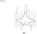
- the product-shape space configured from the plaster mold and the chill is formed by vertically disposing these members so that the chill is higher in position than the plaster mold having a molten metal inlet at the bottom.
- the prepared Al alloy molten metal is poured into the space through the molten metal inlet.
- the molten metal is poured into the space at a pour rate of 0.12 to 1.00m/s at the molten metal inlet.
- the casting step of pressure casting the Al alloy casting by injecting the prepared molten metal into the space is adapted to satisfy the foregoing requirements.
- the refining agent comprised of Al, Ti, and B is added in the molten metal preparation step.
- the amount of the Ti component is less than 0.01%, and/or the amount of the B component is less than 0.002% in the aluminum alloy molten metal after the molten metal preparation step, the primary phase aluminum crystal grains coarsen, which, in turn, coarsens the intermetallic compounds at the grain boundary to lower the strength of the Al alloy material.
- the amount of the Ti component exceeds 0.35%, and/or the amount of the B component exceeds 0.070% in the aluminum alloy molten metal after the molten metal preparation step, coarse TiB 2 aggregates are generated, and become a starting point of fracture.
- the amounts of the Ti and B components in the aluminum alloy molten metal after adding the refining agent in the molten metal preparation step are therefore 0.01 to 0.35% for Ti, and 0.002 to 0.070% for B.
- the product-shape space configured from the plaster mold and the chill is described below.
- the product-shape space 10 configured from a plaster mold 7 and a chill 6 is formed by vertically disposing these members so that the chill 6 is higher in position than the plaster mold 7.
- a molten metal inlet 8 for pouring molten metal into the space 10 is provided at the bottom on the plaster mold 7 side. Molten metal is charged into the space 10 by being poured into the space, from the bottom to the top of the figure, through the molten metal inlet 8 along the molten metal pour direction 9.
- the molten metal thus solidifies earlier in the circumferential section at the bottom side of the space 10 than in the upper circumferential section in the circumferential direction of the compressor impeller, and fails to produce a uniform solid state in the circumferential direction.
- the nonuniform solidification in the circumferential direction of the compressor impeller causes a bend in the shaft section, and produces an imbalance during high-speed rotations.
- the pour rate of molten metal at the molten metal inlet is an important factor in controlling the refining agent content at the disc section end.
- the content of the refining agent particles comprised of Ti and B reaching the end section of the disc section decreases from the content of refining agent particles in the molten metal preparation step. This is due to the refining agent particles failing to follow the moving molten metal during pressure casting in accordance with the law of inertia.
- the excessively fast pour rate of the molten metal makes it even more difficult for the inertial movement of the refining agent particles to follow the pour rate of the molten metal, and the refining agent particles cannot reach the end section of the disc section in amounts that are necessary for grain refining.
- the pour rate of the molten metal at the molten metal inlet is less than 0.12 m/s, the excessively slow pour rate of the molten metal increases the time it takes for the molten metal to reach the plaster mold through the stalk. This lowers the molten metal temperature, and causes solidification failure.
- the pour rate of molten metal at the molten metal inlet is preferably 0.20 to 0.85 m/s.
- the cooling rate at the end section of the disc section of the compressor wheel needs to be controlled. Specifically, the molten metal temperature is controlled between 720 and 780°C, and the temperature of the chill (chill plate) disposed on the surface that contacts the compressor disc surface is controlled between 100 and 250°C.
- the cooling rate at the end section of the disc section is adjusted in a preferred range of 0.1 to 200°C/s by specifying the molten metal temperature and the chill temperature as above.
- the cooling rate is less than 0.1°C/s, the primary phase aluminum crystal grain coarsens, which coarsens the intermetallic compounds generated at the grain boundary. Further, shrinkage cavity occurs, and productivity suffers as the cooling rate decreases.
- the cooling rate at the end section of the disc section is further preferably 3 to 150°C/s.
- the molten metal temperature is below 720°C
- the injected molten metal solidifies early inside the product-shape space. This causes misruns, and the intended product shape cannot be ensured.
- the molten metal progressively undergoes oxidation, and increased porosity numbers due to hydrogen gas absorption, and increased oxides impair the quality of the molten metal. This makes it difficult to ensure product strength.
- the preheating temperature of the plaster mold it is preferable to control the preheating temperature of the plaster mold between 200 and 350°C, though the temperature is not particularly limited.
- the preheating temperature of the plaster mold is less than 200°C, solidification takes place before the charged molten metal fills the mold end. This causes misruns, and the intended product shape cannot be ensured.
- the preheating temperature of the plaster mold exceeds 350°C, the solidification slows down inside the plaster mold, and a shrinkage cavity failure occurs.
- the chill material is preferably copper or a copper alloy, which has high thermal conductivity.
- materials such as steel, and stainless steel also may be used.
- the chill temperature is adjusted by using a mechanism by which superheating in the casting is reduced with a coolant such as water passed inside the chill.
- the producing method includes a molten metal adjusting step, a casting step, and a heat treatment step.
- Each component element is melted under heat to make the Al alloy composition above by using an ordinary method, and molten metal processes such as processing of dehydrogenated gas, and removal of inclusions are performed.
- the temperature is adjusted to make the final molten metal temperature 720 to 780°C.
- the hydrogen gas amount in the molten metal is also adjusted.
- a rotary gas blower is used to adjust the hydrogen gas amount in the molten metal.
- the method is not limited to this.
- the molten metal adjusted to 720 to 780°C is cast into a shape of the compressor impeller by pressure casting using a plaster mold.
- the temperature of the chill disposed on the surface that contacts the disc surface is adjusted to 100°C to 250°C.
- the product-shape space configured from the plaster mold and the chill the product-shape space configured from the plaster mold and the chill is formed by vertically disposing these members so that the chill is higher in position than the plaster mold, as shown in FIG. 3 .
- the molten metal inlet through which the molten metal is poured into the space in molten metal pour direction is provided at the bottom on the plaster mold 7 side.
- the pour rate of the molten metal into the space through the molten metal inlet is adjusted to 0.12 to 1.00 m/s.
- the Al alloy casting is cast by pressure casting whereby the prepared Al alloy molten metal is injected into the space as above.
- the Al alloy casting is subjected to a heat treatment step.
- the heat treatment step includes a solution treatment step and an aging treatment step.
- the heat treatment step can effectively take advantage of the solid solution strengthening by Cu; the precipitation strengthening by Cu and Mg; and the dispersion strengthening by the intermetallic compounds formed by Al and Fe and by Al and Ni.
- the solution treatment is performed preferably in a temperature range that is 5 to 25°C lower than the solidus temperature.
- a temperature range of 510 to 530°C represents such a temperature range that is 5 to 25°C lower than the solidus temperature.
- the risk of melting the second phase of crystal grain boundaries increases, and it becomes difficult to ensure strength at temperatures above the temperature range that is 5 to 25°C lower than the solidus temperature.
- the elements do not diffuse sufficiently, and the solution treatment becomes insufficient at temperatures below the temperature range that is 5 to 25°C lower than the solidus temperature.
- the solution treatment is performed for at least 2 hours.
- the elements do not diffuse sufficiently, and the solution treatment becomes insufficient when the solution treatment is less than 2 hours.
- the solution treatment by element diffusion is performed for preferably 30 hours or less, though the treatment time is not particularly limited as long as the solution treatment is performed for at least 2 hours.
- the aging treatment involves a heat treatment performed preferably at 180 to 230°C for 3 to 30 hours, more preferably 190 to 210°C for 5 to 20 hours.
- the precipitation strengthening for improving strength may become insufficient when the process temperature is below 180°C, or when the process time is less than 3 hours.
- the precipitated phase formed may coarsen (overaging), and may fail to provide a sufficient strengthening effect, and the solid solution strengthening capability of Cu weakens when the process temperature exceeds 230°C, or when the process time exceeds 30 hours.
- the shape and the dimensions of the compressor impeller according to the present invention, and the number of vanes of the compressor impeller are not particularly limited, and the compressor impeller is applicable to many different applications, ranging from large-scale applications such as ships to small-scale applications such as automobiles.
- the boss section has a height of 200 to 80 mm, preferably 180 to 100 mm
- the disc section has a diameter of 300 to 100 mm, preferably 260 to 120 mm
- the vane sections have a height of 180 to 60 mm, preferably 160 to 90 mm.
- the thickness at the tip of the vane is 4.0 to 0.4 mm, preferably 3.0 to 0.6 mm.
- the number of vanes is 30 to 10, preferably 26 to 12.
- the boss section has a height of 100 to 20 mm, preferably 90 to 25 mm
- the disc section has a diameter of 120 to 25 mm, preferably 100 to 30 mm
- the vane sections have a height of 90 to 5 mm, preferably 80 to 8 mm.
- the thickness at the tip of the vane is 3.0 to 0.1 mm, preferably 2.0 to 0.2 mm.
- the number of vanes is 20 to 4, preferably 18 to 6.
- Each Al alloy of the composition shown under the column “Components” in Table 1 was melted by using a common molten metal process, and the molten metal was adjusted to the temperature shown in Table 1 by a molten metal preparation step.
- the molten metal preparation step 150 kg of the Al alloy of the composition shown under the column “Components” in Table 1 was melted to obtain a molten metal.
- a blow degassing process was performed by blowing argon gas into the molten metal for 30 minutes with a rotary gas blower operated at a rotation speed of 400 rpm, and a gas flow rate of 2.5 Nm 3 /h. The whole molten metal was held still for 1 hour to remove the slag.
- the Al alloy molten metal prepared in the molten metal preparation step was then subjected to low-pressure casting to produce an Al alloy casting, whereby the molten metal was pressure injected into a predetermined space configured from a plaster mold that had been adjusted to 250°C, and a copper chill that had been adjusted to the temperature shown in Table 1 and disposed on the surface that contacts the impeller disc surface.
- the molten metal was injected through the molten metal inlet provided at the bottom of the lower plaster mold ( FIG. 3 ), the side of the side plaster mold ( FIG. 4 ), or the top of the upper plaster mold ( FIG. 5 ).
- the Al alloy casting was intended as a turbocharger compressor impeller for cars, and had a shape with a disc section measuring 40 mm in diameter, a boss section measuring 40 mm in height, vane sections measuring 35 mm in height and having 12 vanes that were 0.3 mm in thickness at the vane tip.
- the molten metal was pressure injected into the space configured from the plaster mold and the chill in the directions shown in Table 1 through the molten metal inlet at the pour rates shown in Table 1, and the pressure was maintained until the whole Al alloy casting solidified.
- the Al alloy casting was removed from the plaster mold, and subjected to a solution treatment at 530°C for 8 hours, and thereafter to an aging treatment at 200°C for 20 hours. In this way, a sample Al alloy cast impeller for compressors was prepared.
- the samples produced in the manner described above were each evaluated with respect to the surface density of intermetallic compounds having a circle equivalent size of 1 to 6 ⁇ m at the end section of the disc section, the surface density of intermetallic compounds having a circle equivalent size of more than 6 ⁇ m at the end section of the disc section, amounts of the refining agent components (Ti, B) at the end section of the disc section, amounts of the refining agent components (Ti, B) in sections other than the end section of the disc section, high-temperature characteristics (durability test evaluation), and productivity (casting yield evaluation), as follows.
- FIG. 2 shows a cross section on one side of the central axis 5 of the compressor impeller.
- the end section 31 of the disc section in the cross section was cut and polished, and imaged with an optical microscope at 100 ⁇ magnification.
- the end section 31 of the disc section represents 20% of the disc section from the circumference of the disc section of the compressor impeller to the central axis 5 along the radial direction.
- the image was fed to an image analyzer, and measured for the surface density of intermetallic compounds having a circle equivalent size of 1 to 6 ⁇ m, and the surface density of intermetallic compounds having a circle equivalent size of more than 6 ⁇ m.
- Intermetallic compounds at end section of disc section Amounts of refining agent components at end section of disc section Amounts of refining agent components in sections other than end section of disc section High-temperature characteristics
- Productivity Surface density of intermetallic compounds having circle equivalent size of 1 to 6 ⁇ m (Number of intermetallic compounds/mm 2 ) Surface density of intermetallic compounds having circle equivalent size of more than 6 ⁇ m (Number of intermetallic compounds/mm 2 ) Ti content B content Ti content B content Durability test evaluation Casting yield evaluation Percentage of products with internal defects Percentage of products with misrun defects Percentage of products with shrinkage cavity defects (mass%) (mass%) (mass%) (%) (%) (%) (%) (%) Com.
- the refining agent content was measured at the end section of the disc section, and in sections other than the end section of the disc section. 5 g of sample was collected for analysis from the end section 31 of the disc section, the boss section 2, the vane section 4, and the disc section 32 other than the end section shown in FIG. 2 , and the Ti and B contents were analyzed using an ICP emission spectrometer.
- the amounts of the refining agent components in sections other than the end section of the disc section given in Table 2 were calculated as mean values of the refining agent component amounts determined at the boss section, the vane sections, and the disc section other than the end section. The results are presented in Table 2.
- High-temperature fatigue strength was evaluated in a high-temperature durability test (turbo assembly; 150,000 rpm ⁇ 200 h, outlet temperature 200°C). The results are presented in Table 2. The durability test evaluation results in Table 2 followed the following notation.
- Casting yield was evaluated for 1,000 samples produced in each Example. Each sample was tested for external appearance failure due to misruns and shrinkage cavity failure, and internal failure based on the detected internal blow holes in an X-ray examination. The proportions (%) of samples with misruns, shrinkage cavity failure, and internal failure in all samples were determined. The proportion (%) of non-defective products was then determined by subtracting the sum of the proportions of these defective products from the total 100%. The results are presented in Table 2.
- Comparative Example 1 With a high chill temperature, the surface density was low in the intermetallic compounds having a circle equivalent size of 1 to 6 ⁇ m at the end section of the disc section, and was high in the intermetallic compounds having a circle equivalent size of more than 6 ⁇ m at the end section of the disc section. Because of this, fracture occurred at the end section of the disc section, and the sample was inferior in terms of high-temperature characteristics. Further, multiple shrinkage cavity failures occurred at the boss section, and the casting yield was considerably poor.
- Comparative Example 3 there was a decrease in the molten metal temperature. As a result, multiple defects occurred in the appearance of the vane sections due to misruns and shrinkage cavity, and the casting yield was considerably poor. Further, cracking occurred in the vane sections, and the high-temperature characteristics were poor.
- Comparative Example 14 the amounts of the Ti and B components were high in sections other than the end section of the disc section because of the large amounts of the Ti and B components in the molten metal preparation, and the high pour rate of molten metal into the space mold (here and below, "space mold” refers to the product-shape space configured from the plaster mold and the chill). Because of this, fracture occurred in the boss section, and the high-temperature characteristics were poor. There was also a disturbed molten metal flow in the space mold, and the casting yield was considerably poor because of multiple internal failures.
- Comparative Example 16 because of the large amounts of the Ti and B components in the molten metal preparation, the amounts of the Ti and B components were large in the end section of the disc section, and in sections other than the end section of the disc section. This caused aggregation of refining agent particles. Further, fracture occurred in the disc section, and the high-temperature characteristics were poor.
- Comparative Example 19 because of the lateral pour direction of molten metal into the space mold, nonuniform solidification occurred in the circumferential direction of the compressor impeller. This caused cracking in the boss section due to an axial runout, and the high-temperature characteristics were poor. Further, because the molten metal was nonuniformly charged into the space mold, multiple internal failures occurred, and the casting yield was considerably poor.
- Each Al alloy of the composition shown under the column “Components” in Table 3 was melted by using a common molten metal process, and the molten metal was adjusted to the temperature shown in Table 3 by a molten metal preparation step.
- the molten metal preparation step 150 kg of the Al alloy of the composition shown under the column “Components” in Table 3 was melted to obtain a molten metal.
- a blow degassing process was performed by blowing argon gas into the molten metal for 20 minutes with a rotary gas blower operated at a rotation speed of 400 rpm, and a gas flow rate of 2.5 Nm 3 /h. The whole molten metal was held still for 1 hour to remove the slag.
- the Al alloy molten metal prepared in the molten metal preparation step was then subjected to low-pressure casting to produce an Al alloy casting, whereby the molten metal was pressure injected into a predetermined space configured from a plaster mold that had been adjusted to 220°C, and a copper chill that had been adjusted to the temperature shown in Table 3 and disposed on the surface that contacts the impeller disc surface.
- the Al alloy casting was intended as a turbocharger compressor impeller for trucks, and had a shape with a disc section measuring 80 mm in diameter, a boss section measuring 70 mm in height, vane sections measuring 60 mm in height and having 14 vanes that were 0.4 mm in thickness at the vane tip. As shown in FIG.
- the space configured from the plaster mold and the chill was formed by vertically disposing the plaster mold and the chill so that the chill was higher in position than the plaster mold having a molten metal inlet at the bottom.
- the pour direction of molten metal was upward.
- the molten metal was pressure injected into the space at a pour rate of 0.75 m/s at the molten metal inlet, and the pressure was maintained until the whole Al alloy casting solidified.
- the Al alloy casting was removed from the plaster mold, and subjected to a solution treatment under the conditions shown in Table 3, and thereafter an aging treatment under the conditions of Table 3. In this way, a sample Al alloy cast impeller for compressors was prepared.
- Intermetallic compounds at end section of disc section Amounts of refining agent components at end section of disc section Amounts of refining agent components in sections other than end section of disc section High-temperature characteristics
- Productivity Surface density of intermetallic compounds having circle equivalent size of 1 to 6 ⁇ m (Number of intermetallic compounds/mm 2 ) Surface density of intermetallic compounds having circle equivalent size of more than 6 ⁇ m (Number of intermetallic compounds/mm 2 ) Ti content B content Ti content B content Durability test evaluation Casting yield evaluation Percentage of products with internal defects Percentage of products with misrun defects Percentage of products with shrinkage cavity defects (mass %) (mass %) (mass %) (%) (%) (%) (%) (%) (%) (%) (%) (%) (%) (%) (%) (%) (%) (%) (%) (%) (%) (%) (%) (%) (%) (%) (%) (%) (%) (%) Present Ex.
- Comparative Example 21 the molten metal temperature was low, and the casting yield was poor with multiple failures occurring in the appearance of the vane sections due to misruns. Further, cracking occurred in the vane sections, and the high-temperature characteristics were poor.
- Comparative Example 23 With a low chill temperature, multiple misruns occurred in the disc section, and the casting yield was poor. Further, cracking due to misruns occurred in the disc, and the high-temperature characteristics were poor.
- Comparative Example 24 the chill temperature was high, and the surface density was low in the intermetallic compounds having a circle equivalent size of 1 to 6 ⁇ m at the end section of the disc section, and was high in the intermetallic compounds having a circle equivalent size of more than 6 ⁇ m at the end section of the disc section. This caused fractures in the disc section, and the high-temperature characteristics were poor.
- the solution treatment step was not performed in Comparative Example 25.
- the aging treatment step was not performed in Comparative Example 26. As a result, fracture occurred in the disc section, and the high-temperature characteristics were poor.
- Each Al alloy of the composition shown under the column “Components” in Table 5 was melted by using a common molten metal process, and the molten metal was adjusted to the temperature shown in Table 5 by a molten metal preparation step.
- the molten metal preparation step 200 kg of the Al alloy of the composition shown under the column “Components” in Table 5 was melted to obtain a molten metal.
- a blow degassing process was performed by blowing argon gas into the molten metal for 40 minutes with a rotary gas blower operated at a rotation speed of 400 rpm, and a gas flow rate of 2.5 Nm 3 /h. The whole molten metal was held still for 1.5 hours to remove the slag.
- the Al alloy molten metal prepared in the molten metal preparation step was then subjected to low-pressure casting to produce an Al alloy casting, whereby the molten metal was pressure injected into a predetermined space configured from a plaster mold that had been adjusted to 220°C, and a copper chill that had been adjusted to the temperature shown in Table 5 and disposed on the surface that contacts the impeller disc surface.
- the Al alloy casting was intended as a turbocharger compressor impeller for ships, and had a shape with a disc section measuring 150 mm in diameter, a boss section measuring 160 mm in height, vane sections measuring 120 mm in height and having 16 vanes that were 0.6 mm in thickness at the vane tip. As shown in FIG.
- the space configured from the plaster mold and the chill was formed by vertically disposing the plaster mold and the chill so that the chill was higher in position than the plaster mold having a molten metal inlet at the bottom.
- the pour direction of molten metal was upward.
- the molten metal was pressure injected into the space at a pour rate of 0.95 m/s at the molten metal inlet, and the pressure was maintained until the whole Al alloy casting solidified.
- the Al alloy casting was removed from the plaster mold, and subjected to a solution treatment under the conditions shown in Table 5, and thereafter to an aging treatment under the conditions of Table 5. In this way, a sample Al alloy cast impeller for compressors was prepared.
- Intermetallic compounds at end section of disc section Amounts of refining agent components at end section of disc section Amounts of refining agent components in sections other than end section of disc section High-temperature characteristics
- Productivity Surface density of intermetallic compounds having circle equivalent size of 1 to 6 ⁇ m (Number of intermetallic compounds/mm 2 ) Surface density of intermetallic compounds having circle equivalent size of more than 6 ⁇ m (Number of intermetallic compounds/mm 2 ) Ti content B content Ti content B content Durability test evaluation Casting yield evaluation Percentage of products with internal defects Percentage of products with misrun defects Percentage of products with shrinkage cavity defects (mass%) (mass%) (mass%) (%) (%) (%) (%) (%) (%) (%) (%) (%) (%) (%) (%) (%) (%) (%) (%) Present Ex.
- Comparative Example 27 the molten metal temperature was high, and the cooling rate was low.
- the surface density was therefore low in the intermetallic compounds having a circle equivalent size of 1 to 6 ⁇ m at the end section of the disc section, and was high in the intermetallic compounds having a circle equivalent size of more than 6 ⁇ m at the end section of the disc section. This caused multiple failures in the appearance of the boss section due to shrinkage cavity, and the casting yield was considerably poor. Further, fracture occurred in the disc section, and the high-temperature characteristics were poor.
- Comparative Example 28 the molten metal temperature was low, and the casting yield was poor with multiple failures occurring in the appearance of the vane sections due to misruns . Further, cracking occurred in the vane sections, and the high-temperature characteristics were poor.
- Comparative Example 30 the chill temperature was high, and the surface density was low in the intermetallic compounds having a circle equivalent size of 1 to 6 ⁇ m at the end section of the disc section, and was high in the intermetallic compounds having a circle equivalent size of more than 6 ⁇ m at the end section of the disc section. This caused fractures in the disc section, and the high-temperature characteristics were poor.
- the solution treatment step was not performed in Comparative Example 31, and the aging treatment step was not performed in Comparative Example 32. As a result, the disc section was damaged, and high-temperature characteristics was poor.
- the present invention enables inexpensively providing an Al alloy impeller for compressors that has excellent high-temperature strength, and that can stably withstand an increasing of temperatures due to an increasing of number of rotations over extended time periods.
- the present invention is also industrially very effective in that the output power of an internal combustion engine can be improved by increasing the supercharge ability of a turbocharger.
Landscapes
- Engineering & Computer Science (AREA)
- Mechanical Engineering (AREA)
- Chemical & Material Sciences (AREA)
- Materials Engineering (AREA)
- General Engineering & Computer Science (AREA)
- Organic Chemistry (AREA)
- Metallurgy (AREA)
- Physics & Mathematics (AREA)
- Crystallography & Structural Chemistry (AREA)
- Thermal Sciences (AREA)
- Structures Of Non-Positive Displacement Pumps (AREA)
- Supercharger (AREA)
- Mold Materials And Core Materials (AREA)
- Molds, Cores, And Manufacturing Methods Thereof (AREA)
Description
- The present invention relates to a compressor impeller cast from aluminum alloy for use in turbochargers of the internal combustion engines of automobiles and ships, and to a method for producing same.
- The turbochargers used for the internal combustion engines of automobiles and ships include a compressor impeller that compresses and supplies air into the internal combustion engine by rotating at high speed. The compressor impeller can reach temperatures as high as about 150°C during its high-speed rotation, and receives high stress, such as the torsional stress from the rotating shaft, and the centrifugal force, near the center of rotation, particularly at the disc section.
- Various materials are used for the compressor impeller according to the required performance of the turbocharger. Hot forged materials of an aluminum alloy machined into an impeller shape are typically used in large-scale applications such as ships. Mass production efficiency and costs are more important in relatively smaller applications such as in automobiles (e.g., cars, and trucks), and boats. Such applications commonly use easily castable aluminum alloys of primarily silicon additive such as JIS-AC4CH (Al-7% Si-0.3% Mg alloy), ASTM-354.0 (Al-9% Si-1.8% Cu-0.5% Mg alloy), and ASTM-C355.0 (Al-5% Si-1.3% Cu-0.5% Mg alloy) of desirable castability. These materials are then cast with a plaster mold by using techniques such as low-pressure casting, vacuum casting, and gravity casting, and are strengthened by a solution treatment or an aging treatment before use. A basic method of such procedures is disclosed in detail in
Patent Document 1. - Lately, the need for high-speed turbochargers has increased with the increase in the demand for higher compression ratios of air necessitated by smaller engines, higher output, and increased exhaust recirculation. However, faster rotation speeds increase the amount of heat generated by air compression, and at the same time increase the temperature of the exhaust turbine impeller. The temperature of the compressor impeller is increased by a heat transfer due to heat generation. It has been found that conventional compressor impellers made of easily castable aluminum alloys of primarily silicon additive tend to cause problems such as deformation and fatigue failure during use, and fail to keep rotating normally. Specifically, these existing compressor impellers have an operating temperature of at most about 150°C, and there is a strong need for the development of a compressor impeller that can withstand an operating temperature of about 200°C to meet the demand for high speed rotations.
- It may be possible to use an aluminum alloy composition of more desirable high-temperature strength, for example, such as JIS-AC1B (Al-5% Cu-0.3% Mg alloy). However, as described in
Patent Document 2, the problem of the alloy such as JIS-AC1B is that the molten metal lacks desirable fluidity, and tends to cause misruns (underfilling) of the molten metal in thin section of vane sections when used to make articles that have complex shapes and thin vane sections such as in compressor impellers. -
Patent Document 2 addresses this problem by proposing a method that uses an Al-Si easily castable alloy such as AC4CH for the vane section for which misruns of a molten metal are of concern, and an Al-Cu high-strength alloy such as AC1B for the boss and disk sections that are connected to the rotating shaft and thus require strength. These are coalesced by being poured in two separate sections to form a compressor impeller. -
Patent Document 3 proposes a method that uses an alloy of desirable castability for the vane section, and in which a strengthened composite material prepared by impregnating a strengthening material such as a 25%-B (boron) aluminum whisker with aluminum is used for the stressed boss section and the central section of the disk section. These are then joined to each other to form a compressor impeller. -
Patent Document 4 proposes a method in which a vane section and a boss section (and a disk section) are joined to each other by friction welding. However, methods such as this that use different materials for different sections are problematic in terms of productivity and cost, and are currently not usable in industrial applications. -
Patent Document 5 addresses the problem of using different materials by proposing a compressor impeller that can be cast from a single alloy, specifically an Al-Cu-Mg-base alloy for which the additive elements and the combination range of these elements are optimized. The resulting compressor impeller has a proof stress value of 250 MPa or more at 180°C. Patent Document 6 proposes improving the casting yield by controlling the crystal grain size of an Al-Cu-Mg-base alloy through optimization of the additive elements and the combination range of these elements. The compressor impeller has a proof stress value of 260 MPa or more at 200°C. - Finally,
Patent Document 7 discloses a compressor impeller cast from an Al alloy comprising Cu: 1.4 to 3.2 mass%, Mg: 1.0 to 2.0 mass%, Ni: 0.5 to 2.0 mass%, Fe: 0.5 to 2.0 mass%, Ti: 0.01 to 0.35 mass%, B: 0.002 to 0.070 mass % and a balance of Al and unavoidable impurities. However, a problem remains that the products of the single alloy casting using the Al-Cu-Mg-base alloy still need to stably withstand high temperatures in the vicinity of 200°C over extended time periods if these were to be used for ever faster turbochargers. Another unsolved problem is that the casting yield needs to be improved for stable production. -
- Patent Document 1:
US Patent No. 4,556,528 - Patent Document 2:
JP-A-10-58119 - Patent Document 3:
JP-A-10-212967 - Patent Document 4:
JP-A-11-343858 - Patent Document 5:
JP-A-2005-206927 - Patent Document 6:
JP-A-2012-25986 - Patent Document 7:
JP-5415655B - The present invention has been made in view of the foregoing problems, and it is an obj ect of the present invention to provide a compressor impeller cast from an aluminum alloy (hereinafter, "Al alloy") that remains stably strong over extended time periods even under operating temperatures of about 200°C, and that excels in productivity. The invention is also intended to provide a method for producing such impellers.
- With regard to the foregoing problems, the present inventors focused on the disc section of compressor impellers that receives high stress, and found that the strength of the disc section greatly improves when the intermetallic compounds at the end section of the disc section are finely dispersed. The present inventors also diligently studied a method of production for finely dispersing intermetallic compounds, and found that refining primary phase aluminum crystal grains is important for fine dispersal of intermetallic compounds, and that controlling the cooling rate of Al alloy molten metal, and controlling the distribution of refined particles in a compressor impeller are important to achieve this. The present invention was completed on the basis of these findings.
- In
claim 1, the present invention is directed to a compressor impeller cast from an Al alloy comprising a boss section, a plurality of vane sections and a disc section,
wherein the boss section, the plurality of vane sections, and the disc section excluding an end section comprise an Al alloy comprising Cu: 1.4 to 3.2 mass%, Mg: 1.0 to 2.0 mass%, Ni: 0.5 to 2.0 mass%, Fe: 0.5 to 2.0 mass%, Ti: 0.01 to 0.35 mass%, and B: 0.002 to 0.070 mass% and a balance of Al and unavoidable impurities,
wherein the end section of the disc section comprises an Al alloy comprising Cu: 1.4 to 3.2 mass%, Mg: 1.0 to 2.0 mass%, Ni: 0.5 to 2.0 mass%, Fe: 0.5 to 2.0 mass%, Ti: 0.005 to 0.175 mass%, and B: 0.001 to 0.035 mass% and a balance of Al and unavoidable impurities, and
wherein at least 10000/mm2 of intermetallic compounds having a circle- equivalent diameter of 1 to 6 µm, and no greater than 500/mm2 of intermetallic compounds having a circle-equivalent diameter exceeding 6 µm exist in the end section of the disc section. - In
claim 2 of the present invention, the compressor impeller is for use in large-scale applications including ships, and the boss section has a height of 200 to 80 mm, the disc section has a diameter of 300 to 100 mm and the vane sections have a height of 180 to 60 mm with 30 to 10 vanes measuring 4.0 to 0.4 mm in thickness at the vane tip inclaim 1. - In
claim 3 of the present invention, the compressor impeller is for use in small-scale applications including automobiles, and the boss section has a height of 100 to 20 mm, the disc section has a diameter of 120 to 25 mm, and the vane sections have a height of 90 to 5 mm with 20 to 4 vanes measuring 3.0 to 0.1 mm in thickness at the vane tip inclaim 1. - In
claim 4, the present invention is directed to a method for producing a compressor impeller cast from an Al alloy, comprising: - a step of preparing a 720 to 780°C Al alloy molten metal comprising Cu: 1.4 to 3.2 mass%, Mg: 1.0 to 2.0 mass%, Ni: 0.5 to 2.0 mass%, Fe: 0.5 to 2.0 mass% and a balance of Al and unavoidable impurities, and adding a refining agent to an Al alloy molten metal to incorporate Ti: 0.01 to 0.35 mass% and B: 0.002 to 0.070 mass% in the alloy composition;
- a step of casting the Al alloy casting by pressure casting whereby the Al alloy molten metal prepared is injected through a molten metal inlet into a space having a product shape configured from a plaster mold having the molten metal inlet at the bottom of the plaster mold, and a 100 to 250°C chill disposed on a surface that contacts with an impeller disc surface, the space being formed by disposing the plaster mold and the chill so that the chill is at upper position and the plaster mold is at below position, and an inflow rate at the molten metal inlet into the space being 0.12 to 1.00 m/s;
- a step of solution treating by subjecting the Al alloy casting to a solution treatment; and
- a step of aging treating by subjecting the Al alloy casting to aging after the solution treatment.
- In
claim 5 of the present invention, the end section of the disc section has a cooling rate of 0.1 to 200°C/s in the casting step inclaim 4. - In
claim 6 of the present invention, the Al alloy casting is heat treated for 2 hours or more at atemperature 5 to 25°C below the solidus temperature of the Al alloy in the solution treatment step, and the solution-treated Al alloy casting is subjected to a heat treatment at 180 to 230°C for 3 to 30 hours in the aging treatment step inclaim - The present invention can provide an aluminum alloy cast impeller for compressors that shows stable high-temperature strength even in a high temperature range in the vicinity of 200°C over extended time periods, and that has excellent productivity such as casting yield.
-
-
FIG. 1 is a perspective view representing an exemplary structure of an Al alloy cast impeller for compressors according to the present invention. -
FIG. 2 is an explanatory diagram representing the measurement areas of intermetallic compound distribution in the Al alloy cast impeller for compressors according to the present invention. -
FIG. 3 is an explanatory diagram representing how a plaster mold and a chill are disposed, and the pour direction of molten metal upwardly poured into a space configured from the plaster mold and the chill in a method for producing the Al alloy cast impeller for compressors according to the present invention. -
FIG. 4 is an explanatory diagram representing how the plaster mold and the chill are disposed, and the pour direction of molten metal laterally poured into the space configured from the plaster mold and the chill. -
FIG. 5 is an explanatory diagram representing how the plaster mold and the chill are disposed, and the pour direction of molten metal downwardly poured into the space configured from the plaster mold and the chill. - An embodiment of the present invention is described below in detail.
- After a series of various experimental studies conducted to solve the foregoing problems, the present inventors found that a compressor impeller that stably maintains excellent high-temperature strength over extended time periods without involving damage to the disc section can be obtained by optimizing the size and the surface density of intermetallic compounds at the end section of the disc section of the compressor impeller, even when the compressor impeller is used under high temperatures of about 200°C. It was also found that the size and the surface density of intermetallic compounds at the end section of the disc section of the compressor impeller can be optimized, and that the casting yield can improve from conventional yields by optimizing the Al alloy composition, controlling the cooling rate of casting through adjustments of molten metal temperature and chill temperature, and controlling the pour rate of molten metal into a compressor impeller mold.
- As used herein, "stably maintain desirable high-temperature strength over extended time periods" means that deformation and fatigue failure do not occur over extended time periods even under operating temperatures of about 200°C. Specifically, it means that no damage occurs in a turbo assembly durability test conducted at 200°C for 150, 000 rpm × 200 hours.
-
FIG. 1 shows an example of the shape of the aluminum alloy cast impeller for compressors (hereinafter, simply referred to "compressor impeller") according to the present embodiment. Acompressor impeller 1 includes a rotational center shaft (boss section) 2, adisk section 3 continuous from theboss section 2, and a plurality ofthin vanes 4 projecting outwardly from thedisk section 3. Thecompressor impeller 1 reaches a temperature as high as about 200°C during high-speed rotation, and receives high repeated stress along a vertical direction, particularly at the disk section end. - The composition of the Al alloy used in the present invention is described below along with the reasons for limiting the Al alloy components.
- Cu and Mg dissolve into the Al matrix and show an effect that a mechanical strength is improved by the solid solution strengthening. By existing together, Cu and Mg also contribute to improving strength through precipitation strengthening such as by Al2Cu, and Al2CuMg. Because these two elements widen the solidification temperature range, excess addition of these elements is detrimental to castability.
- When the Cu content is less than 1.4 mass% (hereinafter, simply referred to "%"), and/or Mg content is less than 1.00%, the required mechanical strength at high temperatures of around 200°C may not be obtained. On the other hand, when the Cu content is above 3.2%, and/or Mg content is in excess of 2.0%, the castability of the compressor impeller is impaired, and may cause an underfill as the molten metal fails to sufficiently run into the vane end section in particular. For these reasons, the Cu content should preferably be 1.4 to 3.2%, and the Mg content should preferably be 1.0 to 2.0%. The Cu content is more preferably 1.7 to 2.8%, and the Mg content is more preferably 1.3 to 1.8% in terms of surely preventing defects such as deformation during use, and practically preventing generation of an underfill during casting and obtaining an industrially preferable yield.
- Ni and Fe form an intermetallic compound with Al, and disperse into the Al matrix to improve the high-temperature strength of the Al alloy. To this end, the Ni content should be 0.5% or more, and the Fe content should be 0.5% or more. However, when contained in excess, these elements not only coarsen the intermetallic compound, but reduce the amount of the solid solution Cu in the Al matrix, and lower strength by forming Cu2FeAl7 and Cu3NiAl6 at high temperatures. The presence of coarsened intermetallic compounds at the end section of the disc section causes damage to the compressor impeller as the intermetallic compounds become a starting point of damage under the repeatedly applied stress on the end section of the disc section, as will be described later. It is therefore preferable to contain Ni in a content of 2.0% or less, and Fe in a content of 2.0% or less. Taken together, the Ni content should preferably be 0.5 to 2.0%, and the Fe content should preferably be 0.5 to 2.0%. Preferably, the Ni content is 0.5 to 1.4%, and the Fe content is 0.7 to 1.5%. The lower limits of these preferred ranges are provided as indications for stably mass producing products in industrial settings by reducing production variation, whereas the upper limits are indications above which the effects will be saturated, and the elements will be wasted.
- Ti and B have the effect to inhibit the growth of primary phase aluminum crystal grains during casting, and are added to reduce the size of the solid structure in the casting, and improve the supply and the run of molten metal. These effects may not be sufficiently obtained when the Ti content is less than 0.01%, and/or the B content is less than 0.002% in the boss section, the vane sections, and the disc section other than the end section, or when the Ti content is less than 0.005%, and/or the B content is less than 0.001% in the end section of the disc section. On the other hand, the refining agent particles aggregate, and fatigue cracking occurs from the aggregates when the Ti content exceeds 0.35%, and/or the B content exceeds 0.070% in the boss section, the vane sections, and the disc section other than the end section, or when the Ti content exceeds 0.175%, and/or the B content exceeds 0.035% in the end section of the disc section. When contained in excess of 0.35% in these sections, Ti forms coarse intermetallic compounds of several ten to several hundred micrometers with Al. Such coarse intermetallic compounds become a starting point of fatigue cracking, and lowers the reliability of the compressor impeller. For these reasons, the Ti content should be 0.01 to 0.35%, and the B content should be 0.002 to 0.070%, preferably the Ti content is 0.15 to 0.30%, and the B content is 0.003 to 0.060% in the boss section, the vane sections, and the disc section other than the end section. At the end section of the disc section, the Ti content should be 0.005 to 0.175%, and the B content should be 0.001 to 0.035%, preferably the Ti content is 0.010 to 0.165%, and the B content is 0.002 to 0.033%.
- The Al alloy may contain unavoidable impurities, such as about 0.3% or less of Si, and about 0.2% or less of each of Zn, Mn, and Cr. These unavoidable impurities are acceptable because these do not affect the characteristics of the compressor impeller.
- The aluminum alloy used in the present invention is cast into a shape of the compressor impeller with a plaster mold by pressure casting (low-pressure casting, vacuum casting, or differential pressure casting) according to a conventional Al-Si aluminum alloy casting producing method.
- In the pressure casting using a plaster mold, producing conditions need to be controlled with regard to the distribution of the intermetallic compounds inside each casting in such a manner that the number of intermetallic compounds having a circle-equivalent diameter of 1 to 6 µm is at least 10000/mm2 at the end section of the disc section, and that the number of intermetallic compounds having a circle-equivalent diameter exceeding 6 µm is no greater than 500/mm2 at the end section of the disc section.
- After studying the damaging behavior of the compressor impeller, the present inventors found that end section of the disc section receives repeatedly occurring high normal stress due to acceleration and deceleration of compressor impeller rotation, and becomes damaged as the coarse intermetallic compounds having a circle-equivalent diameter exceeding 6 µm at the end section of the disc section become a starting point of cracking and develop cracks. After further studies, it was also found that cracking originating from such intermetallic compounds, and propagation of cracks, when present, can be inhibited when the intermetallic compounds having a circle-equivalent diameter exceeding 6 µm at the end section of the disc section has a surface density of no greater than 500/mm2. It was also found that generation of the coarse intermetallic compounds can be inhibited when the number of intermetallic compounds having a circle-equivalent diameter of 1 to 6 µm at the end section of the disc section is at least 10000/mm2.
- The generated amounts of intermetallic compounds depend on the composition under typical casting conditions. Here, "under typical casting conditions" means under the cooling rate of low-pressure casting, specifically 0.1 to 200°C/s. Studies of intermetallic compound changes after a post-casting heat treatment revealed that the heat treatment does not have a large effect on the size of the intermetallic compounds generated during casting. By generating large amounts of fine intermetallic compounds during casting, it then becomes possible to inhibit generation of coarse intermetallic compounds in the subsequent heat treatment.
- The reason that the intermetallic compounds having a circle-equivalent diameter of 1 to 6 µm are made to have a surface density of at least 10000/mm2 is as follows. Intermetallic compounds having a circle-equivalent diameter of less than 1 µm do not affect the compressor impeller strength. When the surface density of the intermetallic compounds having a circle-equivalent diameter of 1 to 6 µm is less than 10000/mm2, the generation of intermetallic compounds having a circle-equivalent diameter exceeding 6 µm accelerates, and cracking occurs from the generated intermetallic compounds having a circle-equivalent diameter exceeding 6 µm. The upper limit of the surface density is not particularly limited, and is determined by the composition of the Al alloy, and the producing conditions. In the present invention, the upper limit is 30000/mm2.
- The reason that intermetallic compounds having a circle-equivalent diameter exceeding 6 µm is made to have a surface density of no greater than 500/mm2 is as follows. Intermetallic compounds having a circle-equivalent diameter exceeding 6 µm are of interest for the reason described above. When the surface density exceeds 500/mm2, cracking propagates as the distances between the intermetallic compounds become shorter. The lower limit of the surface density is not particularly limited, and depends on the composition of the Al alloy, and the producing conditions. In the present invention, the lower limit is preferably 100/mm2, most preferably 0/mm2.
- Examples of the intermetallic compounds generated in the present invention include Al-Fe-Ni-Cu, Al-Fe-Cu-Ni-Mg, Al-Cu-Mg, Al-Cu, Al-Cu-Mg-Si, Al-Cu-Fe, Al-Ni, Al-Mg, and Mg-Si intermetallic compounds. The circle equivalent size of the generated intermetallic compounds has a distribution in a range of from 0.1 to 20.0 µm, though it depends on the composition of the Al alloy, and the producing conditions. As used herein, "circle equivalent size" means "circle equivalent diameter."
- Controlling the size of primary phase aluminum crystal grains is important in controlling the distribution of the intermetallic compounds. This is because the intermetallic compounds are generated at the grain boundary of primary phase aluminum crystal grains. Factors that are important in controlling the size of primary phase aluminum crystal grains are amounts of the refining agent components, and the cooling rate which will be described later.
- The appropriate amounts of the Ti and B components in the end section of the disc section are 0.005 to 0.175% for Ti, and 0.001 to 0.035% for B. In order to achieve these refining agent contents, a refining agent comprised of Al, Ti, and B is added in the molten metal preparation step to make the amounts of the Ti and B components 0.01 to 0.35% and 0.002 to 0.070%, respectively, in the aluminum alloy molten metal after the molten metal preparation step. The product-shape space configured from the plaster mold and the chill is formed by vertically disposing these members so that the chill is higher in position than the plaster mold having a molten metal inlet at the bottom. The prepared Al alloy molten metal is poured into the space through the molten metal inlet. The molten metal is poured into the space at a pour rate of 0.12 to 1.00m/s at the molten metal inlet. The casting step of pressure casting the Al alloy casting by injecting the prepared molten metal into the space is adapted to satisfy the foregoing requirements.
- One of the reasons for specifying the foregoing requirements is that only a section of the refining agent amount in the molten metal preparation step reaches the end section of the disc section under the effect of the molten metal flow inside the space. The present inventors have confirmed that this is due to the refining agent particles failing to follow the moving molten metal during pressure casting in accordance with the law of inertia. The following describes this in detail.
- The refining agent comprised of Al, Ti, and B is added in the molten metal preparation step. When the amount of the Ti component is less than 0.01%, and/or the amount of the B component is less than 0.002% in the aluminum alloy molten metal after the molten metal preparation step, the primary phase aluminum crystal grains coarsen, which, in turn, coarsens the intermetallic compounds at the grain boundary to lower the strength of the Al alloy material. When the amount of the Ti component exceeds 0.35%, and/or the amount of the B component exceeds 0.070% in the aluminum alloy molten metal after the molten metal preparation step, coarse TiB2 aggregates are generated, and become a starting point of fracture. The amounts of the Ti and B components in the aluminum alloy molten metal after adding the refining agent in the molten metal preparation step are therefore 0.01 to 0.35% for Ti, and 0.002 to 0.070% for B.
- The product-shape space configured from the plaster mold and the chill is described below. As shown in
FIG. 3 , the product-shape space 10 configured from aplaster mold 7 and achill 6 is formed by vertically disposing these members so that thechill 6 is higher in position than theplaster mold 7. Amolten metal inlet 8 for pouring molten metal into thespace 10 is provided at the bottom on theplaster mold 7 side. Molten metal is charged into thespace 10 by being poured into the space, from the bottom to the top of the figure, through themolten metal inlet 8 along the molten metal pourdirection 9. - Without the
space 10 configured as above, balancing during high-speed rotations of the compressor impeller suffers as a result of the nonuniform solidification occurring in the circumferential direction of the compressor impeller, and operation of the device becomes limited as the casting machine becomes complex. For example, as shownFIG. 4 , when theplaster mold 7 and thechill 6 are horizontally disposed to form the product-shape space 10 configured from these members, the molten metal is charged into thespace 10 by being laterally poured into thespace 10, from the right to left in the figure, through themolten metal inlet 8 along the molten metal pourdirection 9. In this case, the molten metal poured into thespace 10 solidifies as it fills thespace 10 from the bottom to the top. The molten metal thus solidifies earlier in the circumferential section at the bottom side of thespace 10 than in the upper circumferential section in the circumferential direction of the compressor impeller, and fails to produce a uniform solid state in the circumferential direction. The nonuniform solidification in the circumferential direction of the compressor impeller causes a bend in the shaft section, and produces an imbalance during high-speed rotations. - On the other hand, for example, as shown in
FIG. 5 , when the product-shape space 10 configured from theplaster mold 7 and thechill 6 is formed by vertically disposing these members so that theplaster mold 7 is higher in position than thechill 6, the molten metal is charged into thespace 10 by being poured into thespace 10 through themolten metal inlet 8 along the molten metal pourdirection 9 from the top to the bottom of the figure. This complicates the piping of the pipes (stalks) used to charge the molten metal in a furnace into thespace 10. Specifically, a stalk needs to be piped to create a vertically downward flow of the molten metal vertically discharged upward from inside of a furnace in pressure casting. This inevitably complicates the stalk piping. Further, because the stalk distance increases, a lowered molten metal temperature or an increased pressure loss of the molten metal flow makes the casting difficult. - When the product-
shape space 10 is formed by disposing theplaster mold 7 and thechill 6 as shown inFIG. 3 , the nonuniform solid state in circumferential direction seen in the configuration ofFIG. 4 , or the complex stalks, decrease of molten metal temperature, and increase in the pressure loss of the molten metal flow seen in the configuration ofFIG. 5 do not occur. - The pour rate of molten metal at the molten metal inlet is an important factor in controlling the refining agent content at the disc section end. As described above, the content of the refining agent particles comprised of Ti and B reaching the end section of the disc section decreases from the content of refining agent particles in the molten metal preparation step. This is due to the refining agent particles failing to follow the moving molten metal during pressure casting in accordance with the law of inertia. When the pour rate of molten metal at the molten metal inlet exceeds 1.00 m/s, the excessively fast pour rate of the molten metal makes it even more difficult for the inertial movement of the refining agent particles to follow the pour rate of the molten metal, and the refining agent particles cannot reach the end section of the disc section in amounts that are necessary for grain refining. On the other hand, when the pour rate of the molten metal at the molten metal inlet is less than 0.12 m/s, the excessively slow pour rate of the molten metal increases the time it takes for the molten metal to reach the plaster mold through the stalk. This lowers the molten metal temperature, and causes solidification failure. The pour rate of molten metal at the molten metal inlet is preferably 0.20 to 0.85 m/s.
- In order to obtain the intermetallic compound distribution above, the cooling rate at the end section of the disc section of the compressor wheel needs to be controlled. Specifically, the molten metal temperature is controlled between 720 and 780°C, and the temperature of the chill (chill plate) disposed on the surface that contacts the compressor disc surface is controlled between 100 and 250°C. The cooling rate at the end section of the disc section is adjusted in a preferred range of 0.1 to 200°C/s by specifying the molten metal temperature and the chill temperature as above. When the cooling rate is less than 0.1°C/s, the primary phase aluminum crystal grain coarsens, which coarsens the intermetallic compounds generated at the grain boundary. Further, shrinkage cavity occurs, and productivity suffers as the cooling rate decreases. On the other hand, when the cooling rate is above 200°C/s, early solidification occurs inside the product-shape space. This causes misruns, and the intended product shape cannot be ensured. The cooling rate at the end section of the disc section is further preferably 3 to 150°C/s.
- When the molten metal temperature is below 720°C, the injected molten metal solidifies early inside the product-shape space. This causes misruns, and the intended product shape cannot be ensured. On the other hand, with a molten metal temperature above 780°C, the molten metal progressively undergoes oxidation, and increased porosity numbers due to hydrogen gas absorption, and increased oxides impair the quality of the molten metal. This makes it difficult to ensure product strength.
- When the chill temperature is below 100°C, solidification proceeds at an excessive rate, and misruns occur. On the other hand, when the chill temperature is above 250°C, solidification from the chill slows down, and the slow cooling rate coarsens the primary phase aluminum crystal grains, which coarsens the intermetallic compounds generated at the grain boundary. Further, a chill temperature above 250°C causes burr defects, which occur when the molten metal enters between the plaster mold and the chill.
- In the present invention, it is preferable to control the preheating temperature of the plaster mold between 200 and 350°C, though the temperature is not particularly limited. When the preheating temperature of the plaster mold is less than 200°C, solidification takes place before the charged molten metal fills the mold end. This causes misruns, and the intended product shape cannot be ensured. On the other hand, when the preheating temperature of the plaster mold exceeds 350°C, the solidification slows down inside the plaster mold, and a shrinkage cavity failure occurs.
- The chill material is preferably copper or a copper alloy, which has high thermal conductivity. However, materials such as steel, and stainless steel also may be used. Preferably, the chill temperature is adjusted by using a mechanism by which superheating in the casting is reduced with a coolant such as water passed inside the chill.
- A method for producing the Al alloy cast impeller for compressors according to the present invention is described below. The producing method includes a molten metal adjusting step, a casting step, and a heat treatment step.
- Each component element is melted under heat to make the Al alloy composition above by using an ordinary method, and molten metal processes such as processing of dehydrogenated gas, and removal of inclusions are performed. The temperature is adjusted to make the final molten metal temperature 720 to 780°C. The hydrogen gas amount in the molten metal is also adjusted. A rotary gas blower is used to adjust the hydrogen gas amount in the molten metal. However, the method is not limited to this.
- In the casting step, the molten metal adjusted to 720 to 780°C is cast into a shape of the compressor impeller by pressure casting using a plaster mold. As described above, the temperature of the chill disposed on the surface that contacts the disc surface is adjusted to 100°C to 250°C. As for the product-shape space configured from the plaster mold and the chill, the product-shape space configured from the plaster mold and the chill is formed by vertically disposing these members so that the chill is higher in position than the plaster mold, as shown in
FIG. 3 . The molten metal inlet through which the molten metal is poured into the space in molten metal pour direction is provided at the bottom on theplaster mold 7 side. The pour rate of the molten metal into the space through the molten metal inlet is adjusted to 0.12 to 1.00 m/s. The Al alloy casting is cast by pressure casting whereby the prepared Al alloy molten metal is injected into the space as above. - The Al alloy casting is subjected to a heat treatment step. The heat treatment step includes a solution treatment step and an aging treatment step. The heat treatment step can effectively take advantage of the solid solution strengthening by Cu; the precipitation strengthening by Cu and Mg; and the dispersion strengthening by the intermetallic compounds formed by Al and Fe and by Al and Ni.
- The solution treatment is performed preferably in a temperature range that is 5 to 25°C lower than the solidus temperature. In the preferred Al alloys for use in the present invention, a temperature range of 510 to 530°C represents such a temperature range that is 5 to 25°C lower than the solidus temperature. The risk of melting the second phase of crystal grain boundaries increases, and it becomes difficult to ensure strength at temperatures above the temperature range that is 5 to 25°C lower than the solidus temperature. On the other hand, the elements do not diffuse sufficiently, and the solution treatment becomes insufficient at temperatures below the temperature range that is 5 to 25°C lower than the solidus temperature. Preferably, the solution treatment is performed for at least 2 hours. The elements do not diffuse sufficiently, and the solution treatment becomes insufficient when the solution treatment is less than 2 hours. Considering mass production, the solution treatment by element diffusion is performed for preferably 30 hours or less, though the treatment time is not particularly limited as long as the solution treatment is performed for at least 2 hours.
- The aging treatment involves a heat treatment performed preferably at 180 to 230°C for 3 to 30 hours, more preferably 190 to 210°C for 5 to 20 hours. The precipitation strengthening for improving strength may become insufficient when the process temperature is below 180°C, or when the process time is less than 3 hours. On the other hand, the precipitated phase formed may coarsen (overaging), and may fail to provide a sufficient strengthening effect, and the solid solution strengthening capability of Cu weakens when the process temperature exceeds 230°C, or when the process time exceeds 30 hours.
- The shape and the dimensions of the compressor impeller according to the present invention, and the number of vanes of the compressor impeller are not particularly limited, and the compressor impeller is applicable to many different applications, ranging from large-scale applications such as ships to small-scale applications such as automobiles. Taking a large scale application such as ships as an example, the boss section has a height of 200 to 80 mm, preferably 180 to 100 mm, the disc section has a diameter of 300 to 100 mm, preferably 260 to 120 mm, and the vane sections have a height of 180 to 60 mm, preferably 160 to 90 mm. The thickness at the tip of the vane is 4.0 to 0.4 mm, preferably 3.0 to 0.6 mm. The number of vanes is 30 to 10, preferably 26 to 12. In the case of smaller applications such as automobiles, the boss section has a height of 100 to 20 mm, preferably 90 to 25 mm, the disc section has a diameter of 120 to 25 mm, preferably 100 to 30 mm, and the vane sections have a height of 90 to 5 mm, preferably 80 to 8 mm. The thickness at the tip of the vane is 3.0 to 0.1 mm, preferably 2.0 to 0.2 mm. The number of vanes is 20 to 4, preferably 18 to 6.
- The present invention is described below in greater detail using Examples.
- Each Al alloy of the composition shown under the column "Components" in Table 1 was melted by using a common molten metal process, and the molten metal was adjusted to the temperature shown in Table 1 by a molten metal preparation step. In the molten metal preparation step, 150 kg of the Al alloy of the composition shown under the column "Components" in Table 1 was melted to obtain a molten metal. Thereafter, a blow degassing process was performed by blowing argon gas into the molten metal for 30 minutes with a rotary gas blower operated at a rotation speed of 400 rpm, and a gas flow rate of 2.5 Nm3/h. The whole molten metal was held still for 1 hour to remove the slag. After the slag removal, a refining agent was added to the molten metal in the metal preparation step to make the amounts of Ti and B components as shown under the column "Amounts of refining agent components after molten metal preparation" in Table 1.
[Table 1] No. Components (mass%) Casting conditions Amounts of refining agent components after molten metal preparation (mass%) Heat treatment conditions Cu Mg Ni Fe Al Molten metal temp. (°C) Chill temp. (°C) Plaster mold temp. (°C) Pour rate of molten metal into mold (m/s) Molten metal pour direction Ti B Solution treatment temp. × time (°C × hour) Aging treatment temp. × time (°C × hour) Present Ex. 1 3.2 2.0 1.9 2.0 760 210 206 0.15 Upward 0.10 0.020 Present Ex. 2 3.1 1.9 1.4 1.5 780 250 201 0.90 Upward 0.20 0.040 Present Ex. 3 2.2 1.6 0.8 1.0 760 110 267 0.35 Upward 0.15 0.030 Present Ex. 4 1.6 1.4 0.6 0.7 740 220 250 0.12 Upward 0.35 0.070 Present Ex. 5 2.6 1.6 0.8 1.1 750 130 240 1.00 Upward 0.13 0.020 Present Ex. 6 1.4 1.2 1.2 1.0 720 240 210 0.85 Upward 0.08 0.015 Present Ex. 7 2.4 1.0 0.5 0.5 740 230 350 0.20 Upward 0.01 0.002 Com. Ex. 1 2.9 1.7 1.6 1.1 770 260 304 0.45 Upward 0.05 0.010 Com. Ex. 2 2.0 1.1 1.2 0.9 740 90 341 0.75 Upward 0.27 0.050 Com. Ex. 3 2.1 1.2 1.4 1.5 710 160 319 0.80 Upward 0.21 0.040 Com. Ex. 4 2.5 1.3 1.7 1.3 790 200 239 0.90 Upward 0.12 0.020 Com. Ex. 5 1.3 1.9 1.4 1.2 730 180 312 0.45 Upward 0.07 0.012 Com. Ex. 6 2.8 0.9 1.1 1.4 Remainder 750 190 330 0.30 Upward 0.15 0.030 Com. Ex. 7 3.0 1.4 1.4 0.4 excluding Ti 760 170 230 0.20 Upward 0.23 0.045 530 × 8 200 × 20 Com. Ex. 8 2.9 1.3 0.4 1.7 and B 770 200 235 0.30 Upward 0.18 0.035 Com. Ex. 9 2.6 1.4 0.9 1.2 765 210 197 0.50 Upward 0.01 0.001 Com. Ex. 10 3.3 1.8 1.1 1.2 740 185 316 0.80 Upward 0.23 0.045 Com. Ex. 11 2.5 2.1 0.9 1.1 750 150 231 0.90 Upward 0.19 0.036 Com. Ex. 12 2.9 1.5 1.4 2.1 730 225 279 0.30 Upward 0.26 0.050 Com. Ex. 13 2.2 1.6 2.1 1.2 760 190 289 0.80 Upward 0.18 0.036 Com. Ex. 14 2.9 1.3 1.2 1.2 740 210 366 1.20 Upward 0.38 0.075 Com. Ex. 15 2.8 1.1 1.7 0.9 750 220 260 1.50 Upward 0.02 0.003 Com. Ex. 16 3.0 1.6 0.8 1.0 740 190 296 0.90 Upward 0.37 0.072 Com. Ex. 17 2.0 1.1 1.2 0.9 760 180 244 0.11 Upward 0.27 0.050 Com. Ex. 18 2.9 1.3 1.7 1.2 730 240 231 1.01 Upward 0.23 0.015 Com. Ex. 19 2.5 1.3 1.1 1.2 740 170 348 0.75 Lateral 0.26 0.050 Com. Ex. 20 3.1 1.6 0.9 1.1 770 200 256 0.20 Downward 0.20 0.040 - The Al alloy molten metal prepared in the molten metal preparation step was then subjected to low-pressure casting to produce an Al alloy casting, whereby the molten metal was pressure injected into a predetermined space configured from a plaster mold that had been adjusted to 250°C, and a copper chill that had been adjusted to the temperature shown in Table 1 and disposed on the surface that contacts the impeller disc surface. Here, the molten metal was injected through the molten metal inlet provided at the bottom of the lower plaster mold (
FIG. 3 ), the side of the side plaster mold (FIG. 4 ), or the top of the upper plaster mold (FIG. 5 ). The Al alloy casting was intended as a turbocharger compressor impeller for cars, and had a shape with a disc section measuring 40 mm in diameter, a boss section measuring 40 mm in height, vane sections measuring 35 mm in height and having 12 vanes that were 0.3 mm in thickness at the vane tip. The molten metal was pressure injected into the space configured from the plaster mold and the chill in the directions shown in Table 1 through the molten metal inlet at the pour rates shown in Table 1, and the pressure was maintained until the whole Al alloy casting solidified. - The Al alloy casting was removed from the plaster mold, and subjected to a solution treatment at 530°C for 8 hours, and thereafter to an aging treatment at 200°C for 20 hours. In this way, a sample Al alloy cast impeller for compressors was prepared.
- The samples produced in the manner described above were each evaluated with respect to the surface density of intermetallic compounds having a circle equivalent size of 1 to 6 µm at the end section of the disc section, the surface density of intermetallic compounds having a circle equivalent size of more than 6 µm at the end section of the disc section, amounts of the refining agent components (Ti, B) at the end section of the disc section, amounts of the refining agent components (Ti, B) in sections other than the end section of the disc section, high-temperature characteristics (durability test evaluation), and productivity (casting yield evaluation), as follows.
- The samples were cut along the central axis to determine the size and the surface density of intermetallic compounds at the end section of the disc section.
FIG. 2 shows a cross section on one side of thecentral axis 5 of the compressor impeller. The end section 31 of the disc section in the cross section was cut and polished, and imaged with an optical microscope at 100 × magnification. Here, the end section 31 of the disc section represents 20% of the disc section from the circumference of the disc section of the compressor impeller to thecentral axis 5 along the radial direction. The image was fed to an image analyzer, and measured for the surface density of intermetallic compounds having a circle equivalent size of 1 to 6 µm, and the surface density of intermetallic compounds having a circle equivalent size of more than 6 µm. The measurements were made at arbitrarily selected 10 measurement points, and the arithmetic mean value was calculated as surface density. Each measurement point had a view area of 1 mm2. The results are presented in Table 2.[Table 2] No. Intermetallic compounds at end section of disc section Amounts of refining agent components at end section of disc section Amounts of refining agent components in sections other than end section of disc section High-temperature characteristics Productivity Surface density of intermetallic compounds having circle equivalent size of 1 to 6 µm (Number of intermetallic compounds/mm2) Surface density of intermetallic compounds having circle equivalent size of more than 6 µm (Number of intermetallic compounds/mm2) Ti content B content Ti content B content Durability test evaluation Casting yield evaluation Percentage of products with internal defects Percentage of products with misrun defects Percentage of products with shrinkage cavity defects (mass%) (mass%) (mass%) (mass%) (%) (%) (%) Present Ex. 1 14546 250 0.047 0.009 0.10 0.019 Good Good 1.0 0.3 0.8 Present Ex. 2 15460 393 0.029 0.006 0.13 0.026 Good Good 2.2 0.1 1.2 Present Ex. 3 29970 101 0.060 0.012 0.14 0.027 Good Good 1.8 0.2 0.4 Present Ex. 4 12318 469 0.175 0.035 0.35 0.070 Good Good 1.1 1.0 0.6 Present Ex. 5 14948 390 0.008 0.002 0.06 0.012 Good Good 1.4 0.4 1.6 Present Ex. 6 15727 230 0.012 0.002 0.05 0.010 Good Acceptable 2.5 2.1 1.8 Present Ex. 7 22814 110 0.005 0.001 0.01 0.002 Good Acceptable 2.1 0.8 3.4 Com. Ex. 1 9386 670 0.017 0.003 0.04 0.008 Poor Poor 2.8 0.2 9.5 Com. Ex. 2 24385 197 0.052 0.010 0.18 0.035 Good Poor 4.2 30.4 4.6 Com. Ex. 3 17715 227 0.038 0.008 0.14 0.028 Acceptable Poor 2.6 38.6 12.2 Com. Ex. 4 8659 471 0.012 0.002 0.06 0.012 Poor Poor 5.5 0.7 20.1 Com. Ex. 5 19094 207 0.018 0.004 0.05 0.010 Good Poor 1.2 25.1 1.3 Com. Ex. 6 19429 199 0.063 0.013 0.14 0.028 Acceptable Good 1.6 0.6 1.7 Com. Ex. 7 10934 405 0.104 0.021 0.22 0.043 Acceptable Good 0.8 0.8 1.8 Com. Ex. 8 11170 397 0.072 0.014 0.16 0.032 Poor Good 1.0 0.7 2.6 Com. Ex. 9 7472 577 0.004 0.000 0.00 0.001 Poor Poor 3.5 36.0 1.0 Com. Ex. 10 12773 356 0.044 0.009 0.16 0.031 Poor Acceptable 2.1 2.3 1.1 No. Intermetallic compounds at end section of disc section Amounts of refining agent components at end section of disc section Amounts of refining agent components in sections other than end section of disc section High-temperature characteristics Productivity Surface density of intermetallic compounds having circle equivalent size of 1 to 6 µm (Number of intermetallic compounds/mm2) Surface density of intermetallic compounds having circle equivalent size of more than 6 µm (Number of intermetallic compounds/mm2) Ti content B content Ti content B content Durability test evaluation Casting yield evaluation Percentage of products with internal defects Percentage of products with misrun defects Percentage of products with shrinkage cavity defects (mass%) (mass%) (mass%) (mass%) (%) (%) (%) Com. Ex. 11 16344 247 0.016 0.003 0.11 0.021 Good Poor 1.6 47.1 7.1 Com. Ex. 12 40896 713 0.101 0.020 0.23 0.045 Acceptable Acceptable 4.1 2.4 2.5 Com. Ex. 13 31311 565 0.034 0.007 0.12 0.025 Acceptable Acceptable 2.6 2.3 3.3 Com. Ex. 14 12130 360 0.150 0.030 0.36 0.072 Poor Poor 46.9 0.3 0.2 Com. Ex. 15 6386 583 0.000 0.000 0.01 0.002 Poor Poor 50.1 0.2 0.2 Com. Ex. 16 27598 173 0.180 0.036 0.36 0.071 Poor Good 1.3 0.1 1.4 Com. Ex. 17 14208 328 0.128 0.026 0.25 0.051 Acceptable Poor 2.3 37.3 2.2 Com. Ex. 18 14625 271 0.004 0.001 0.04 0.008 Acceptable Poor 39.3 3.7 0.2 Com. Ex. 19 11412 363 0.051 0.010 0.18 0.035 Poor Poor 21.6 0.3 1.4 Com. Ex. 20 26824 191 0.086 0.017 0.19 0.037 Acceptable Poor 1.9 11.6 1.8 - The refining agent content was measured at the end section of the disc section, and in sections other than the end section of the disc section. 5 g of sample was collected for analysis from the end section 31 of the disc section, the
boss section 2, thevane section 4, and thedisc section 32 other than the end section shown inFIG. 2 , and the Ti and B contents were analyzed using an ICP emission spectrometer. The amounts of the refining agent components in sections other than the end section of the disc section given in Table 2 were calculated as mean values of the refining agent component amounts determined at the boss section, the vane sections, and the disc section other than the end section. The results are presented in Table 2. - High-temperature fatigue strength was evaluated in a high-temperature durability test (turbo assembly; 150,000 rpm × 200 h, outlet temperature 200°C). The results are presented in Table 2. The durability test evaluation results in Table 2 followed the following notation.
-
- Acceptable: No fracture, but cracking is occurred
- Good: No fracture or cracking, and the sample remained intact
- The parentheses following Acceptable and Poor indicate the location of the occurred cracks and fractures.
- Casting yield was evaluated for 1,000 samples produced in each Example. Each sample was tested for external appearance failure due to misruns and shrinkage cavity failure, and internal failure based on the detected internal blow holes in an X-ray examination. The proportions (%) of samples with misruns, shrinkage cavity failure, and internal failure in all samples were determined. The proportion (%) of non-defective products was then determined by subtracting the sum of the proportions of these defective products from the total 100%. The results are presented in Table 2.
- Poor: The proportion of non-defective products is less than 90% (worse than in existing products)
- Acceptable: The proportion of non-defective products is 90% or more and less than 95% (same as in existing products)
- Good: The proportion of non-defective products is 95% to 100% (great improvement over existing products)
- In Present Examples 1 to 7, the surface density of intermetallic compounds having a circle equivalent size of 1 to 6 µm at the end section of the disc section, the surface density of intermetallic compounds having a circle equivalent size of more than 6 µm at the end section of the disc section, and the refining agent contents in the end section of the disc section and in sections other than the end section fell in the specified ranges, and because of this, the high-temperature characteristics, and the casting yield were both desirable.
- In Comparative Example 1, with a high chill temperature, the surface density was low in the intermetallic compounds having a circle equivalent size of 1 to 6 µm at the end section of the disc section, and was high in the intermetallic compounds having a circle equivalent size of more than 6 µm at the end section of the disc section. Because of this, fracture occurred at the end section of the disc section, and the sample was inferior in terms of high-temperature characteristics. Further, multiple shrinkage cavity failures occurred at the boss section, and the casting yield was considerably poor.
- In Comparative Example 2, with a low chill temperature, multiple defects occurred in the appearance of the disc section due to misruns, and the casting yield was poor.
- In Comparative Example 3, there was a decrease in the molten metal temperature. As a result, multiple defects occurred in the appearance of the vane sections due to misruns and shrinkage cavity, and the casting yield was considerably poor. Further, cracking occurred in the vane sections, and the high-temperature characteristics were poor.
- In Comparative Example 4, the molten metal temperature was high, and the cooling rate was low. The surface density was therefore low in the intermetallic compounds having a circle equivalent size of 1 to 6 µm at the end section of the disc section. As a result, multiple defects occurred in the appearance of the boss section due to shrinkage cavity, and the casting yield was considerably poor. Further, cracking occurred in the end section of the disc section, and the high-temperature characteristics were poor.
- In Comparative Example 5, with the low Cu content, the high-temperature characteristics were desirable. However, there was a high incidence of misruns in the vane sections, and the casting yield was poor.
- In Comparative Example 6, with the low Mg content, cracking occurred in the boss section, and the high-temperature characteristics were poor.
- In Comparative Example 7, with the low Fe content, cracking occurred in the vane sections, and the high-temperature characteristics were poor.
- In Comparative Example 8, with the low Ni content, fracture occurred in the disc section, and the high-temperature characteristics were poor.
- In Comparative Example 9, with the small amount of refining agent component (B) in the molten metal preparation, the amounts of the Ti and B components became small in the end section of the disc section, and in sections other than the end section of the disc section. The grain refining effect was therefore insufficient, and the surface density was low in the intermetallic compounds having a circle equivalent size of 1 to 6 µm in the end section of the disc section, and was high in the intermetallic compounds having a circle equivalent size of more than 6 µm. As a result, multiple defects occurred in the appearance of the vane sections due to misruns, and the casting yield was considerably poor. Further, fracture occurred in the disc section, and the high-temperature characteristics were poor.
- In Comparative Example 10, with the high Cu content, fracture occurred in the disc section, and high-temperature characteristics were poor.
- In Comparative Example 11, with the high Mg content, multiple misruns occurred in the vane sections, and the casting yield was poor, though the high-temperature characteristics were desirable.
- In Comparative Example 12, with the high Fe content, the intermetallic compounds having a circle equivalent size of more than 6 µm had a high surface density. Because of this, cracking occurred in the disc section, and the high-temperature characteristics were poor.
- In Comparative Example 13, with the high Ni content, the intermetallic compounds having a circle equivalent size of more than 6 µm had a high surface density. Because of this, cracking occurred in the disc section, and the high-temperature characteristics were poor.
- In Comparative Example 14, the amounts of the Ti and B components were high in sections other than the end section of the disc section because of the large amounts of the Ti and B components in the molten metal preparation, and the high pour rate of molten metal into the space mold (here and below, "space mold" refers to the product-shape space configured from the plaster mold and the chill). Because of this, fracture occurred in the boss section, and the high-temperature characteristics were poor. There was also a disturbed molten metal flow in the space mold, and the casting yield was considerably poor because of multiple internal failures.
- In Comparative Example 15, the amounts of the Ti and B components in the end section of the disc section were small (0%) because of the high pour rate of molten metal into the space mold, though the amounts of the Ti and B components in the molten metal preparation were in the specified ranges. Because of this, the grain refining effect was insufficient, and the surface density was low in the intermetallic compounds having a circle equivalent size of 1 to 6 µm in the end section of the disc section, and was high in the intermetallic compounds having a circle equivalent size of more than 6 µm. As a result, fracture occurred in the disc section, and the high-temperature characteristics were poor. There was also a disturbed molten metal flow in the space mold, and the casting yield was considerably poor because of multiple internal failures.
- In Comparative Example 16, because of the large amounts of the Ti and B components in the molten metal preparation, the amounts of the Ti and B components were large in the end section of the disc section, and in sections other than the end section of the disc section. This caused aggregation of refining agent particles. Further, fracture occurred in the disc section, and the high-temperature characteristics were poor.
- In Comparative Example 17, because of the slow pour rate of molten metal into the plaster mold, the molten metal temperature decreased in the process of delivering the molten metal to the plaster mold. This caused multiple failures in the appearance of the vane sections due to misruns, and the casting yield was considerably poor. Further, cracking occurred in the vane sections, and the high-temperature characteristics were poor.
- In Comparative Example 18, because of the high pour rate of molten metal into the plaster mold, the inertial movement of the refining agent particles had difficulties following the pour rate of the molten metal. Because of this, the Ti content was low in the end section of the disc section, and the refining agent particles failed to reach the end section of the disc section in sufficient amounts. Refining of crystal grains therefore did not take place, and coarse intermetallic compounds were created. This caused cracking in the end section of the disc section, and the high-temperature characteristics were poor. There was also a disturbed molten metal flow in the space mold, and the casting yield was considerably poor because of multiple internal failures.
- In Comparative Example 19, because of the lateral pour direction of molten metal into the space mold, nonuniform solidification occurred in the circumferential direction of the compressor impeller. This caused cracking in the boss section due to an axial runout, and the high-temperature characteristics were poor. Further, because the molten metal was nonuniformly charged into the space mold, multiple internal failures occurred, and the casting yield was considerably poor.
- In Comparative Example 20, because of the downward pour direction of molten metal into the space mold, the molten metal temperature decreased in the process of delivering the molten metal to the plaster mold. This caused multiple failures in the appearance of the disc section due to misruns, and the casting yield was considerably poor. Further, cracking occurred in the disc section, and the high-temperature characteristics were poor.
- Each Al alloy of the composition shown under the column "Components" in Table 3 was melted by using a common molten metal process, and the molten metal was adjusted to the temperature shown in Table 3 by a molten metal preparation step. In the molten metal preparation step, 150 kg of the Al alloy of the composition shown under the column "Components" in Table 3 was melted to obtain a molten metal. Thereafter, a blow degassing process was performed by blowing argon gas into the molten metal for 20 minutes with a rotary gas blower operated at a rotation speed of 400 rpm, and a gas flow rate of 2.5 Nm3/h. The whole molten metal was held still for 1 hour to remove the slag. After the slag removal, a refining agent was added to the molten metal in the metal preparation step to make the amounts of the Ti and B components as shown under the column "Amounts of refining agent components after molten metal preparation" in Table 3.
[Table 3] No. Components (mass%) Casting conditions Amounts of refining agent components after molten metal preparation (mass%) Heat treatment conditions Cu Mg Ni Fe Al Molten metal temp. (°C) Chill temp. (°C) Ti B Solution treatment temp. × time (°C × hour) Aging treatment temp. × time (°C × hour) Present Ex. 8 780 200 525 × 5 190 × 16 Present Ex. 9 760 170 515 × 10 190 × 24 Present Ex. 10 770 240 515 × 10 190 × 24 Present Ex. 11 720 150 530 × 4 230 × 9 Present Ex. 12 740 160 505 × 10 230 × 9 Present Ex. 13 740 140 535 × 2 230 × 9 Present Ex. 14 750 210 520 × 8 200 × 2 Present Ex. 15 Remainder excluding Ti and B 750 220 520 × 8 200 × 34 Present Ex. 16 2.6 1.6 1.1 0.9 740 180 0.15 0.03 520 × 8 170 × 24 Present Ex. 17 740 200 520 × 8 240 × 24 Present Ex. 18 760 110 525 × 1 200 × 20 Com. Ex. 21 715 200 520 × 6 200 × 16 Com. Ex. 22 785 220 520 × 6 200 × 16 Com. Ex. 23 740 90 520 × 6 200 × 16 Com. Ex. 24 750 260 520 × 6 200 × 16 Com. Ex. 25 760 190 None 190 × 24 Com. Ex. 26 740 200 530 × 6 None - The Al alloy molten metal prepared in the molten metal preparation step was then subjected to low-pressure casting to produce an Al alloy casting, whereby the molten metal was pressure injected into a predetermined space configured from a plaster mold that had been adjusted to 220°C, and a copper chill that had been adjusted to the temperature shown in Table 3 and disposed on the surface that contacts the impeller disc surface. The Al alloy casting was intended as a turbocharger compressor impeller for trucks, and had a shape with a disc section measuring 80 mm in diameter, a boss section measuring 70 mm in height, vane sections measuring 60 mm in height and having 14 vanes that were 0.4 mm in thickness at the vane tip. As shown in
FIG. 3 , the space configured from the plaster mold and the chill was formed by vertically disposing the plaster mold and the chill so that the chill was higher in position than the plaster mold having a molten metal inlet at the bottom. The pour direction of molten metal was upward. The molten metal was pressure injected into the space at a pour rate of 0.75 m/s at the molten metal inlet, and the pressure was maintained until the whole Al alloy casting solidified. - The Al alloy casting was removed from the plaster mold, and subjected to a solution treatment under the conditions shown in Table 3, and thereafter an aging treatment under the conditions of Table 3. In this way, a sample Al alloy cast impeller for compressors was prepared.
- The samples produced in the manner described above were each evaluated in the same manner as in First Example with respect to the surface density of intermetallic compounds having a circle equivalent size of 1 to 6 µm at the end section of the disc section, the surface density of intermetallic compounds having a circle equivalent size of more than 6 µm at the end section of the disc section, amounts of the refining agent components (Ti, B) at the end section of the disc section, amounts of the refining agent components (Ti, B) in sections other than the end section of the disc section, high-temperature characteristics (durability test evaluation), and productivity (casting yield evaluation). The results are presented in Table 4. For high-temperature characteristics, samples that scored "Good" in the evaluation of First Example were further tested for 100 hours for a total of 300 hours under the same conditions (turbo assembly, 150000 rpm, output temperature 200°C). Samples that produced desirable results after the 300-hour test were evaluated as "Excellent."
[Table 4] No. Intermetallic compounds at end section of disc section Amounts of refining agent components at end section of disc section Amounts of refining agent components in sections other than end section of disc section High-temperature characteristics Productivity Surface density of intermetallic compounds having circle equivalent size of 1 to 6 µm (Number of intermetallic compounds/mm2) Surface density of intermetallic compounds having circle equivalent size of more than 6 µm (Number of intermetallic compounds/mm2) Ti content B content Ti content B content Durability test evaluation Casting yield evaluation Percentage of products with internal defects Percentage of products with misrun defects Percentage of products with shrinkage cavity defects (mass %) (mass %) (mass %) (mass %) (%) (%) (%) Present Ex. 8 15576 284 0.048 0.010 0.12 0.025 Excellent Good 1.3 0.4 1.1 Present Ex. 9 11382 410 0.018 0.004 0.09 0.019 Excellent Good 1.9 0.2 2.0 Present Ex. 10 12225 387 0.066 0.013 0.14 0.028 Excellent Good 1.5 0.3 2.3 Present Ex. 11 11837 404 0.011 0.002 0.09 0.017 Excellent Good 2.3 0.8 1.2 Present Ex. 12 15759 252 0.024 0.005 0.10 0.020 Good Good 2.1 0.9 1.2 Present Ex. 13 12905 359 0.012 0.002 0.09 0.017 Good Good 1.3 1.1 1.3 Present Ex. 14 13780 317 0.053 0.011 0.13 0.026 Good Good 1.8 0.4 2.1 Present Ex. 15 15647 283 0.057 0.011 0.13 0.026 Good Good 1.6 0.2 2.3 Present Ex. 16 10027 424 0.024 0.005 0.10 0.020 Good Good 1.5 1.2 1.5 Present Ex. 17 16027 235 0.038 0.008 0.11 0.023 Good Good 2.1 0.3 2.1 Present Ex. 18 15633 303 0.023 0.004 0.09 0.019 Good Good 1.2 0.6 2.1 Com. Ex. 21 14007 299 0.032 0.006 0.11 0.021 Acceptable Poor 6.3 26.3 2.3 Com. Ex. 22 6448 766 0.063 0.013 0.14 0.028 Poor Poor 2.5 1.2 17.3 Com. Ex. 23 13743 332 0.009 0.002 0.08 0.017 Acceptable Poor 1.5 38.1 4.1 Com. Ex. 24 8335 549 0.075 0.015 0.15 0.030 Poor Acceptable 2.0 1.1 5.2 Com. Ex. 25 16103 232 0.032 0.006 0.11 0.021 Poor Good 1.6 0.3 1.5 Com. Ex. 26 16187 231 0.045 0.009 0.12 0.024 Poor Good 1.1 1.0 1.2 - In Present Examples 8 to 18, the surface density of intermetallic compounds having a circle equivalent size of 1 to 6 µm at the end section of the disc section, the surface density of intermetallic compounds having a circle equivalent size of more than 6 µm at the end section of the disc section, and the amounts of the refining agent components in the end section of the disc section and in sections other than the end section fell in the specified ranges, and because of this, the high-temperature characteristics, and the casting yield were both desirable.
- On the other hand, in Comparative Example 21, the molten metal temperature was low, and the casting yield was poor with multiple failures occurring in the appearance of the vane sections due to misruns. Further, cracking occurred in the vane sections, and the high-temperature characteristics were poor.
- In Comparative Example 22, the molten metal temperature was high, and the cooling rate was low. The surface density was therefore low in the intermetallic compounds having a circle equivalent size of 1 to 6 µm at the end section of the disc section, and was high in the intermetallic compounds having a circle equivalent size of more than 6 µm at the end section of the disc section. This caused multiple failures in the appearance of the boss section due to shrinkage cavity, and the casting yield was considerably poor. Further, fracture occurred in the disc section, and the high-temperature characteristics were poor.
- In Comparative Example 23, with a low chill temperature, multiple misruns occurred in the disc section, and the casting yield was poor. Further, cracking due to misruns occurred in the disc, and the high-temperature characteristics were poor.
- In Comparative Example 24, the chill temperature was high, and the surface density was low in the intermetallic compounds having a circle equivalent size of 1 to 6 µm at the end section of the disc section, and was high in the intermetallic compounds having a circle equivalent size of more than 6 µm at the end section of the disc section. This caused fractures in the disc section, and the high-temperature characteristics were poor.
- The solution treatment step was not performed in Comparative Example 25. The aging treatment step was not performed in Comparative Example 26. As a result, fracture occurred in the disc section, and the high-temperature characteristics were poor.
- Each Al alloy of the composition shown under the column "Components" in Table 5 was melted by using a common molten metal process, and the molten metal was adjusted to the temperature shown in Table 5 by a molten metal preparation step. In the molten metal preparation step, 200 kg of the Al alloy of the composition shown under the column "Components" in Table 5 was melted to obtain a molten metal. Thereafter, a blow degassing process was performed by blowing argon gas into the molten metal for 40 minutes with a rotary gas blower operated at a rotation speed of 400 rpm, and a gas flow rate of 2.5 Nm3/h. The whole molten metal was held still for 1.5 hours to remove the slag. After the slag removal, a refining agent was added to the molten metal in the metal preparation step to make the amounts of the Ti and B components as shown under the column "Amounts of refining agent components after molten metal preparation" in Table 5.
[Table 5] No. Components (mass%) Casting conditions Amounts of refining agent components after molten metal preparation (mass%) Heat treatment conditions Cu Mg Ni Fe Al Molten metal temp. (°C) Chill temp. (°C) Ti B Solution treatment temp. × time (°C × hour) Aging treatment temp. × time (°C × hour) Present Ex. 19 770 200 525 × 6 190 × 22 Present Ex. 20 780 230 510 × 8 190 × 22 Present Ex. 21 760 240 515 × 10 190 × 22 Present Ex. 22 740 190 530 × 4 200 × 12 Present Ex. 23 760 180 505 × 8 200 × 12 Present Ex. 24 730 150 535 × 3 200 × 12 Present Ex. 25 750 220 515 × 8 220 × 2 Present Ex. 26 Remainder 720 250 515 × 8 220 × 32 Present Ex. 27 2.9 1.7 1.1 1.1 excluding Ti and B 730 120 0.17 0.02 515 × 8 175 × 24 Present Ex. 28 720 100 515 × 8 235 × 20 Com. Ex. 27 785 200 530 × 4 195 × 18 Com. Ex. 28 715 180 530 × 4 195 × 18 Com. Ex. 29 740 95 530 × 4 195 × 18 Com. Ex. 30 750 255 530 × 4 195 × 18 Com. Ex. 31 760 180 None 195 × 18 Com. Ex. 32 750 210 530 × 4 None - The Al alloy molten metal prepared in the molten metal preparation step was then subjected to low-pressure casting to produce an Al alloy casting, whereby the molten metal was pressure injected into a predetermined space configured from a plaster mold that had been adjusted to 220°C, and a copper chill that had been adjusted to the temperature shown in Table 5 and disposed on the surface that contacts the impeller disc surface. The Al alloy casting was intended as a turbocharger compressor impeller for ships, and had a shape with a disc section measuring 150 mm in diameter, a boss section measuring 160 mm in height, vane sections measuring 120 mm in height and having 16 vanes that were 0.6 mm in thickness at the vane tip. As shown in
FIG. 3 , the space configured from the plaster mold and the chill was formed by vertically disposing the plaster mold and the chill so that the chill was higher in position than the plaster mold having a molten metal inlet at the bottom. The pour direction of molten metal was upward. The molten metal was pressure injected into the space at a pour rate of 0.95 m/s at the molten metal inlet, and the pressure was maintained until the whole Al alloy casting solidified. - The Al alloy casting was removed from the plaster mold, and subjected to a solution treatment under the conditions shown in Table 5, and thereafter to an aging treatment under the conditions of Table 5. In this way, a sample Al alloy cast impeller for compressors was prepared.
- The samples produced in the manner described above were each evaluated in the same manner as in First Example with respect to the surface density of intermetallic compounds having a circle equivalent size of 1 to 6 µm at the end section of the disc section, the surface density of intermetallic compounds having a circle equivalent size of more than 6 µm at the end section of the disc section, amounts of the refining agent components (Ti, B) at the end section of the disc section, amounts of the refining agent components (Ti, B) in sections other than the end section of the disc section, high-temperature characteristics (durability test evaluation), and productivity (casting yield evaluation). The results are presented in Table 6.
[Table 6] No. Intermetallic compounds at end section of disc section Amounts of refining agent components at end section of disc section Amounts of refining agent components in sections other than end section of disc section High-temperature characteristics Productivity Surface density of intermetallic compounds having circle equivalent size of 1 to 6 µm (Number of intermetallic compounds/mm2) Surface density of intermetallic compounds having circle equivalent size of more than 6 µm (Number of intermetallic compounds/mm2) Ti content B content Ti content B content Durability test evaluation Casting yield evaluation Percentage of products with internal defects Percentage of products with misrun defects Percentage of products with shrinkage cavity defects (mass%) (mass%) (mass%) (mass%) (%) (%) (%) Present Ex. 19 11759 207 0.022 0.004 0.07 0.014 Excellent Good 1.6 0.4 1.2 Present Ex. 20 11460 245 0.034 0.007 0.08 0.017 Excellent Good 1.2 0.3 2.2 Present Ex. 21 11769 236 0.037 0.007 0.09 0.017 Excellent Good 1.4 0.4 2.1 Present Ex. 22 13697 164 0.022 0.004 0.07 0.014 Excellent Good 1.9 0.6 1.6 Present Ex. 23 12648 177 0.019 0.004 0.07 0.014 Good Good 2.5 0.7 1.0 Present Ex. 24 13975 153 0.015 0.003 0.07 0.013 Good Good 1.5 1.0 1.6 Present Ex. 25 10856 362 0.032 0.006 0.08 0.016 Good Good 1.1 0.5 2.3 Present Ex. 26 13036 170 0.045 0.009 0.10 0.019 Good Good 1.8 0.4 2.1 Present Ex. 27 11416 255 0.014 0.003 0.06 0.013 Good Good 1.4 1.1 2.0 Present Ex. 28 11316 301 0.013 0.003 0.06 0.013 Good Good 2.2 0.4 1.8 Com. Ex. 27 7235 642 0.022 0.004 0.07 0.014 Poor Poor 5.5 0.8 31.8 Com. Ex. 28 12243 205 0.015 0.003 0.07 0.013 Acceptable Poor 3.1 60.1 1.8 Com. Ex. 29 10490 420 0.006 0.001 0.06 0.011 Acceptable Poor 2.2 41.4 3.7 Com. Ex. 30 9244 524 0.039 0.008 0.09 0.018 Poor Acceptable 3.0 1.0 4.8 Com. Ex. 31 10506 494 0.018 0.004 0.07 0.014 Poor Good 1.3 0.4 1.1 Com. Ex. 32 12598 186 0.029 0.006 0.08 0.016 Poor Good 1.5 0.8 1.0 - In Present Examples 19 to 28, the surface density of intermetallic compounds having a circle equivalent size of 1 to 6 µm at the end section of the disc section, the surface density of intermetallic compounds having a circle equivalent size of more than 6 µm at the end section of the disc section, and the amounts of the refining agent components in the end section of the disc section and in sections other than the end section fell in the specified ranges, and the high-temperature characteristics, and the casting yield were both desirable.
- On the other hand, in Comparative Example 27, the molten metal temperature was high, and the cooling rate was low. The surface density was therefore low in the intermetallic compounds having a circle equivalent size of 1 to 6 µm at the end section of the disc section, and was high in the intermetallic compounds having a circle equivalent size of more than 6 µm at the end section of the disc section. This caused multiple failures in the appearance of the boss section due to shrinkage cavity, and the casting yield was considerably poor. Further, fracture occurred in the disc section, and the high-temperature characteristics were poor.
- In Comparative Example 28, the molten metal temperature was low, and the casting yield was poor with multiple failures occurring in the appearance of the vane sections due to misruns . Further, cracking occurred in the vane sections, and the high-temperature characteristics were poor.
- In Comparative Example 29, with the low chill temperature, multiple misruns occurred in the disc section, and the casting yield was poor. Further, cracking due to misruns occurred in the disc, and the high-temperature characteristics were poor.
- In Comparative Example 30, the chill temperature was high, and the surface density was low in the intermetallic compounds having a circle equivalent size of 1 to 6 µm at the end section of the disc section, and was high in the intermetallic compounds having a circle equivalent size of more than 6 µm at the end section of the disc section. This caused fractures in the disc section, and the high-temperature characteristics were poor.
- The solution treatment step was not performed in Comparative Example 31, and the aging treatment step was not performed in Comparative Example 32. As a result, the disc section was damaged, and high-temperature characteristics was poor.
- The present invention enables inexpensively providing an Al alloy impeller for compressors that has excellent high-temperature strength, and that can stably withstand an increasing of temperatures due to an increasing of number of rotations over extended time periods. The present invention is also industrially very effective in that the output power of an internal combustion engine can be improved by increasing the supercharge ability of a turbocharger.
-
- 1 Compressor impeller
- 2 Boss section
- 3 Disc section
- 31 End section of disc section
- 32 Disc section excluding end section
- 4 Vane section
- 5 Central axis
- 6 Chill
- 7 Plaster mold
- 8 Molten metal inlet
- 9 Molten metal pour direction
- 10 Product-shape space configured from plaster mold and chill
Claims (6)
- A compressor impeller cast from an Al alloy comprising a boss section, a plurality of vane sections and a disc section,
wherein the boss section, the plurality of vane sections, and the disc section excluding an end section comprise an Al alloy comprising Cu: 1.4 to 3.2 mass%, Mg: 1.0 to 2.0 mass%, Ni: 0.5 to 2.0 mass%, Fe: 0.5 to 2.0 mass%, Ti: 0.01 to 0.35 mass%, and B: 0.002 to 0.070 mass% and a balance of Al and unavoidable impurities,
wherein the end section of the disc section comprises an Al alloy comprising Cu: 1.4 to 3.2 mass%, Mg: 1.0 to 2.0 mass%, Ni: 0.5 to 2.0 mass%, Fe: 0.5 to 2.0 mass%, Ti: 0.005 to 0.175 mass%, and B: 0.001 to 0.035 mass% and a balance of Al and unavoidable impurities, and
wherein at least 10000/mm2 of intermetallic compounds having a circle-equivalent diameter of 1 to 6 µm, and no greater than 500/mm2 of intermetallic compounds having a circle-equivalent diameter exceeding 6 µm exist in the end section of the disc section. - The compressor impeller cast from the Al alloy according to claim 1,
wherein the compressor impeller is for use in large-scale applications including ships, and
wherein the boss section has a height of 200 to 80 mm, the disc section has a diameter of 300 to 100 mm and the vane sections have a height of 180 to 60 mm with 30 to 10 vanes measuring 4.0 to 0.4 mm in thickness at the vane tip. - The compressor impeller cast from the Al alloy according to claim 1,
wherein the compressor impeller is for use in small-scale applications including automobiles, and
wherein the boss section has a height of 100 to 20 mm, the disc section has a diameter of 120 to 25 mm, and the vane sections have a height of 90 to 5 mm with 20 to 4 vanes measuring 3.0 to 0.1 mm in thickness at the vane tip. - A method for producing a compressor impeller cast from an Al alloy, comprising:a step of preparing a 720 to 780°C Al alloy molten metal comprising Cu: 1.4 to 3.2 mass%, Mg: 1.0 to 2.0 mass%, Ni: 0.5 to 2.0 mass%, Fe: 0.5 to 2.0 mass% and a balance of Al and unavoidable impurities, and adding a refining agent to an Al alloy molten metal to incorporate Ti: 0.01 to 0.35 mass% and B: 0.002 to 0.070 mass% in the alloy composition;a step of casting the Al alloy casting by pressure casting whereby the Al alloy molten metal prepared is injected through a molten metal inlet into a space having a product shape configured from a plaster mold having the molten metal inlet at the bottom of the plaster mold, and a 100 to 250°C chill disposed on a surface that contacts with an impeller disc surface, the space being formed by disposing the plaster mold and the chill so that the chill is at upper position and the plaster mold is at below position, and an inflow rate at the molten metal inlet into the space being 0.12 to 1.00 m/s;a step of solution treating by subjecting the Al alloy casting to a solution treatment; anda step of aging treating by subjecting the Al alloy casting to aging after the solution treatment.
- The method for producing the compressor impeller cast from the Al alloy according to claim 4, wherein the end section of the disc section has a cooling rate of 0.1 to 200°C/s in the casting step.
- The method for producing the compressor impeller cast from the Al alloy according to claim 4 or 5,
wherein the Al alloy casting is heat treated for 2 hours or more at a temperature 5 to 25°C below the solidus temperature of the Al alloy in the solution treatment step, and
wherein the solution-treated Al alloy casting is subjected to a heat treatment at 180 to 230°C for 3 to 30 hours in the aging treatment step.
Applications Claiming Priority (2)
| Application Number | Priority Date | Filing Date | Title |
|---|---|---|---|
| JP2014052840 | 2014-03-15 | ||
| PCT/JP2015/001340 WO2015141191A1 (en) | 2014-03-15 | 2015-03-11 | Compressor impeller cast from al alloy and method for producing same |
Publications (3)
| Publication Number | Publication Date |
|---|---|
| EP3121303A1 EP3121303A1 (en) | 2017-01-25 |
| EP3121303A4 EP3121303A4 (en) | 2017-03-15 |
| EP3121303B1 true EP3121303B1 (en) | 2018-01-03 |
Family
ID=54144175
Family Applications (1)
| Application Number | Title | Priority Date | Filing Date |
|---|---|---|---|
| EP15764543.3A Not-in-force EP3121303B1 (en) | 2014-03-15 | 2015-03-11 | Compressor impeller cast from al alloy and method for producing same |
Country Status (5)
| Country | Link |
|---|---|
| US (1) | US20170107600A1 (en) |
| EP (1) | EP3121303B1 (en) |
| JP (1) | JPWO2015141191A1 (en) |
| CN (1) | CN106170572A (en) |
| WO (1) | WO2015141191A1 (en) |
Families Citing this family (7)
| Publication number | Priority date | Publication date | Assignee | Title |
|---|---|---|---|---|
| WO2015087907A1 (en) * | 2013-12-13 | 2015-06-18 | 昭和電工株式会社 | Formed material for turbo-compressor wheel made of aluminum alloy, and method of manufacturing turbo-compressor wheel |
| CN105382239A (en) * | 2015-12-21 | 2016-03-09 | 常熟市制冷压缩机铸件厂 | Aluminum compressor housing of refrigerator |
| JP7020031B2 (en) * | 2017-09-28 | 2022-02-16 | 日本電産株式会社 | Manufacturing method of impeller, impeller, blower, and blower |
| JP2019065359A (en) * | 2017-10-03 | 2019-04-25 | 株式会社豊田自動織機 | Compressor component for aluminum powder alloy-made transport excellent in mechanical property at high temperature, and manufacturing method therefor |
| CN108730229B (en) * | 2018-05-22 | 2020-07-28 | 江苏昊科汽车空调有限公司 | High-strength compressor impeller |
| CN112743044A (en) * | 2020-12-29 | 2021-05-04 | 上海蓝铸特种合金材料有限公司 | Precision casting method of ultra-fine grain size high-temperature alloy impeller |
| CN114309455B (en) * | 2021-12-17 | 2023-04-18 | 山东豪迈机械科技股份有限公司 | Method for eliminating local thermal section of gypsum mold casting |
Family Cites Families (10)
| Publication number | Priority date | Publication date | Assignee | Title |
|---|---|---|---|---|
| JPS5910459A (en) * | 1982-07-08 | 1984-01-19 | Honda Motor Co Ltd | Precise casting method |
| GB2409423B (en) * | 2003-12-23 | 2007-04-11 | Doncasters Ltd | Metal casting apparatus and method |
| JP4290024B2 (en) * | 2004-01-26 | 2009-07-01 | 古河スカイ株式会社 | Compressor impeller made of cast aluminum alloy for turbochargers with excellent heat resistance |
| JP2008264846A (en) * | 2007-04-23 | 2008-11-06 | Hitachi Metal Precision:Kk | Method for manufacturing impeller |
| JP4958292B2 (en) * | 2007-07-19 | 2012-06-20 | 日立金属株式会社 | Aluminum die-cast alloy, cast compressor impeller made of this alloy, and method for manufacturing the same |
| JP2010053743A (en) * | 2008-08-27 | 2010-03-11 | Hitachi Metals Ltd | Die-cast compressor impeller |
| JP5598895B2 (en) * | 2009-01-14 | 2014-10-01 | 株式会社日立メタルプレシジョン | Aluminum die-cast alloy, cast compressor impeller made of this alloy, and method for manufacturing the same |
| JP2012025986A (en) * | 2010-07-21 | 2012-02-09 | Furukawa-Sky Aluminum Corp | Aluminum-alloy cast compressor impeller and its manufacturing method |
| JP5415655B1 (en) * | 2012-10-26 | 2014-02-12 | 株式会社Uacj | Compressor impeller made of Al alloy casting and manufacturing method thereof |
| JP2015013301A (en) * | 2013-07-04 | 2015-01-22 | 株式会社Ihi | Compressor impeller molding device and method |
-
2015
- 2015-03-11 WO PCT/JP2015/001340 patent/WO2015141191A1/en active Application Filing
- 2015-03-11 US US15/125,185 patent/US20170107600A1/en not_active Abandoned
- 2015-03-11 JP JP2016508521A patent/JPWO2015141191A1/en active Pending
- 2015-03-11 CN CN201580014056.5A patent/CN106170572A/en active Pending
- 2015-03-11 EP EP15764543.3A patent/EP3121303B1/en not_active Not-in-force
Non-Patent Citations (1)
| Title |
|---|
| None * |
Also Published As
| Publication number | Publication date |
|---|---|
| WO2015141191A1 (en) | 2015-09-24 |
| JPWO2015141191A1 (en) | 2017-04-06 |
| US20170107600A1 (en) | 2017-04-20 |
| EP3121303A4 (en) | 2017-03-15 |
| EP3121303A1 (en) | 2017-01-25 |
| CN106170572A (en) | 2016-11-30 |
Similar Documents
| Publication | Publication Date | Title |
|---|---|---|
| EP3121303B1 (en) | Compressor impeller cast from al alloy and method for producing same | |
| EP2913122B1 (en) | Al alloy cast impeller for compressor and process for producing same | |
| US7435305B2 (en) | Cast aluminum alloy compressor wheel for a turbocharger | |
| EP1767292B1 (en) | Method of casting an aluminum alloy by controlled solidification | |
| WO2008001758A1 (en) | Casting aluminum alloy, cast compressor impeller comprising the alloy, and process for producing the same | |
| Wallace et al. | High-quality aluminum turbocharger impellers produced by thixocasting | |
| JPS5816047A (en) | Nickel base alloy | |
| JP2012025986A (en) | Aluminum-alloy cast compressor impeller and its manufacturing method | |
| KR101829292B1 (en) | Turbocharger and compressor wheel therefor | |
| JP4409409B2 (en) | Ni-Fe base superalloy, method for producing the same, and gas turbine | |
| JP4845201B2 (en) | Aluminum die-cast alloy and compressor impeller using the same | |
| JP4958292B2 (en) | Aluminum die-cast alloy, cast compressor impeller made of this alloy, and method for manufacturing the same | |
| CN113862520B (en) | GH4720Li high-temperature alloy for aero-engine forged blade, preparation method and application thereof, and alloy ingot | |
| JP2009041066A (en) | Die-cast component of magnesium superior in heat resistance, cast compressor impeller and manufacturing method therefor | |
| JP2015178671A (en) | Turbine wheel of turbo charger for automobile and manufacturing method therefor | |
| JPH11246925A (en) | Aluminum alloy casting with high toughness, and its manufacture | |
| JP5083965B2 (en) | Casting compressor impeller | |
| JP2008088460A (en) | High-strength aluminum casting alloy and compressor impeller using the same | |
| JP2017155268A (en) | Al ALLOY CAST ARTICLE-MADE COMPRESSOR IMPELLER | |
| JP5415655B1 (en) | Compressor impeller made of Al alloy casting and manufacturing method thereof | |
| JP2019218612A (en) | Aluminum alloy cast made compressor impeller excellent in creep resistance, and manufacturing method therefor | |
| JP2015059531A (en) | COMPRESSOR IMPELLER MADE OF Al ALLOY CASTING, AND METHOD FOR MANUFACTURING THE SAME | |
| CN111172431B (en) | Small-displacement turbocharger impeller and production process thereof | |
| JPS62170464A (en) | Manufacture of moving vane for turbine | |
| CN115870449A (en) | Protective coating for die, preparation method of protective coating, powder material and die-casting die |
Legal Events
| Date | Code | Title | Description |
|---|---|---|---|
| PUAI | Public reference made under article 153(3) epc to a published international application that has entered the european phase |
Free format text: ORIGINAL CODE: 0009012 |
|
| 17P | Request for examination filed |
Effective date: 20160816 |
|
| AK | Designated contracting states |
Kind code of ref document: A1 Designated state(s): AL AT BE BG CH CY CZ DE DK EE ES FI FR GB GR HR HU IE IS IT LI LT LU LV MC MK MT NL NO PL PT RO RS SE SI SK SM TR |
|
| AX | Request for extension of the european patent |
Extension state: BA ME |
|
| A4 | Supplementary search report drawn up and despatched |
Effective date: 20170209 |
|
| RIC1 | Information provided on ipc code assigned before grant |
Ipc: F04D 29/30 20060101ALI20170203BHEP Ipc: F02B 39/00 20060101ALI20170203BHEP Ipc: B22C 9/22 20060101ALI20170203BHEP Ipc: B22C 9/02 20060101ALI20170203BHEP Ipc: C22C 21/12 20060101AFI20170203BHEP Ipc: B22D 18/04 20060101ALI20170203BHEP Ipc: B22D 21/04 20060101ALI20170203BHEP Ipc: C22F 1/057 20060101ALI20170203BHEP |
|
| DAV | Request for validation of the european patent (deleted) | ||
| DAX | Request for extension of the european patent (deleted) | ||
| GRAP | Despatch of communication of intention to grant a patent |
Free format text: ORIGINAL CODE: EPIDOSNIGR1 |
|
| INTG | Intention to grant announced |
Effective date: 20170718 |
|
| GRAS | Grant fee paid |
Free format text: ORIGINAL CODE: EPIDOSNIGR3 |
|
| GRAA | (expected) grant |
Free format text: ORIGINAL CODE: 0009210 |
|
| AK | Designated contracting states |
Kind code of ref document: B1 Designated state(s): AL AT BE BG CH CY CZ DE DK EE ES FI FR GB GR HR HU IE IS IT LI LT LU LV MC MK MT NL NO PL PT RO RS SE SI SK SM TR |
|
| REG | Reference to a national code |
Ref country code: GB Ref legal event code: FG4D |
|
| REG | Reference to a national code |
Ref country code: CH Ref legal event code: EP Ref country code: AT Ref legal event code: REF Ref document number: 960336 Country of ref document: AT Kind code of ref document: T Effective date: 20180115 |
|
| REG | Reference to a national code |
Ref country code: IE Ref legal event code: FG4D |
|
| REG | Reference to a national code |
Ref country code: DE Ref legal event code: R096 Ref document number: 602015007249 Country of ref document: DE |
|
| REG | Reference to a national code |
Ref country code: NL Ref legal event code: MP Effective date: 20180103 |
|
| REG | Reference to a national code |
Ref country code: LT Ref legal event code: MG4D |
|
| PGFP | Annual fee paid to national office [announced via postgrant information from national office to epo] |
Ref country code: IE Payment date: 20180326 Year of fee payment: 4 |
|
| REG | Reference to a national code |
Ref country code: AT Ref legal event code: MK05 Ref document number: 960336 Country of ref document: AT Kind code of ref document: T Effective date: 20180103 |
|
| PG25 | Lapsed in a contracting state [announced via postgrant information from national office to epo] |
Ref country code: NL Free format text: LAPSE BECAUSE OF FAILURE TO SUBMIT A TRANSLATION OF THE DESCRIPTION OR TO PAY THE FEE WITHIN THE PRESCRIBED TIME-LIMIT Effective date: 20180103 |
|
| PG25 | Lapsed in a contracting state [announced via postgrant information from national office to epo] |
Ref country code: FI Free format text: LAPSE BECAUSE OF FAILURE TO SUBMIT A TRANSLATION OF THE DESCRIPTION OR TO PAY THE FEE WITHIN THE PRESCRIBED TIME-LIMIT Effective date: 20180103 Ref country code: HR Free format text: LAPSE BECAUSE OF FAILURE TO SUBMIT A TRANSLATION OF THE DESCRIPTION OR TO PAY THE FEE WITHIN THE PRESCRIBED TIME-LIMIT Effective date: 20180103 Ref country code: NO Free format text: LAPSE BECAUSE OF FAILURE TO SUBMIT A TRANSLATION OF THE DESCRIPTION OR TO PAY THE FEE WITHIN THE PRESCRIBED TIME-LIMIT Effective date: 20180403 Ref country code: ES Free format text: LAPSE BECAUSE OF FAILURE TO SUBMIT A TRANSLATION OF THE DESCRIPTION OR TO PAY THE FEE WITHIN THE PRESCRIBED TIME-LIMIT Effective date: 20180103 Ref country code: LT Free format text: LAPSE BECAUSE OF FAILURE TO SUBMIT A TRANSLATION OF THE DESCRIPTION OR TO PAY THE FEE WITHIN THE PRESCRIBED TIME-LIMIT Effective date: 20180103 Ref country code: CY Free format text: LAPSE BECAUSE OF FAILURE TO SUBMIT A TRANSLATION OF THE DESCRIPTION OR TO PAY THE FEE WITHIN THE PRESCRIBED TIME-LIMIT Effective date: 20180103 |
|
| PG25 | Lapsed in a contracting state [announced via postgrant information from national office to epo] |
Ref country code: GR Free format text: LAPSE BECAUSE OF FAILURE TO SUBMIT A TRANSLATION OF THE DESCRIPTION OR TO PAY THE FEE WITHIN THE PRESCRIBED TIME-LIMIT Effective date: 20180404 Ref country code: PL Free format text: LAPSE BECAUSE OF FAILURE TO SUBMIT A TRANSLATION OF THE DESCRIPTION OR TO PAY THE FEE WITHIN THE PRESCRIBED TIME-LIMIT Effective date: 20180103 Ref country code: BG Free format text: LAPSE BECAUSE OF FAILURE TO SUBMIT A TRANSLATION OF THE DESCRIPTION OR TO PAY THE FEE WITHIN THE PRESCRIBED TIME-LIMIT Effective date: 20180403 Ref country code: RS Free format text: LAPSE BECAUSE OF FAILURE TO SUBMIT A TRANSLATION OF THE DESCRIPTION OR TO PAY THE FEE WITHIN THE PRESCRIBED TIME-LIMIT Effective date: 20180103 Ref country code: IS Free format text: LAPSE BECAUSE OF FAILURE TO SUBMIT A TRANSLATION OF THE DESCRIPTION OR TO PAY THE FEE WITHIN THE PRESCRIBED TIME-LIMIT Effective date: 20180503 Ref country code: SE Free format text: LAPSE BECAUSE OF FAILURE TO SUBMIT A TRANSLATION OF THE DESCRIPTION OR TO PAY THE FEE WITHIN THE PRESCRIBED TIME-LIMIT Effective date: 20180103 Ref country code: LV Free format text: LAPSE BECAUSE OF FAILURE TO SUBMIT A TRANSLATION OF THE DESCRIPTION OR TO PAY THE FEE WITHIN THE PRESCRIBED TIME-LIMIT Effective date: 20180103 Ref country code: AT Free format text: LAPSE BECAUSE OF FAILURE TO SUBMIT A TRANSLATION OF THE DESCRIPTION OR TO PAY THE FEE WITHIN THE PRESCRIBED TIME-LIMIT Effective date: 20180103 |
|
| REG | Reference to a national code |
Ref country code: DE Ref legal event code: R119 Ref document number: 602015007249 Country of ref document: DE |
|
| PG25 | Lapsed in a contracting state [announced via postgrant information from national office to epo] |
Ref country code: EE Free format text: LAPSE BECAUSE OF FAILURE TO SUBMIT A TRANSLATION OF THE DESCRIPTION OR TO PAY THE FEE WITHIN THE PRESCRIBED TIME-LIMIT Effective date: 20180103 Ref country code: AL Free format text: LAPSE BECAUSE OF FAILURE TO SUBMIT A TRANSLATION OF THE DESCRIPTION OR TO PAY THE FEE WITHIN THE PRESCRIBED TIME-LIMIT Effective date: 20180103 Ref country code: IT Free format text: LAPSE BECAUSE OF FAILURE TO SUBMIT A TRANSLATION OF THE DESCRIPTION OR TO PAY THE FEE WITHIN THE PRESCRIBED TIME-LIMIT Effective date: 20180103 |
|
| REG | Reference to a national code |
Ref country code: CH Ref legal event code: PL |
|
| PLBE | No opposition filed within time limit |
Free format text: ORIGINAL CODE: 0009261 |
|
| STAA | Information on the status of an ep patent application or granted ep patent |
Free format text: STATUS: NO OPPOSITION FILED WITHIN TIME LIMIT |
|
| PG25 | Lapsed in a contracting state [announced via postgrant information from national office to epo] |
Ref country code: CZ Free format text: LAPSE BECAUSE OF FAILURE TO SUBMIT A TRANSLATION OF THE DESCRIPTION OR TO PAY THE FEE WITHIN THE PRESCRIBED TIME-LIMIT Effective date: 20180103 Ref country code: MC Free format text: LAPSE BECAUSE OF FAILURE TO SUBMIT A TRANSLATION OF THE DESCRIPTION OR TO PAY THE FEE WITHIN THE PRESCRIBED TIME-LIMIT Effective date: 20180103 Ref country code: SK Free format text: LAPSE BECAUSE OF FAILURE TO SUBMIT A TRANSLATION OF THE DESCRIPTION OR TO PAY THE FEE WITHIN THE PRESCRIBED TIME-LIMIT Effective date: 20180103 Ref country code: DK Free format text: LAPSE BECAUSE OF FAILURE TO SUBMIT A TRANSLATION OF THE DESCRIPTION OR TO PAY THE FEE WITHIN THE PRESCRIBED TIME-LIMIT Effective date: 20180103 Ref country code: SM Free format text: LAPSE BECAUSE OF FAILURE TO SUBMIT A TRANSLATION OF THE DESCRIPTION OR TO PAY THE FEE WITHIN THE PRESCRIBED TIME-LIMIT Effective date: 20180103 |
|
| REG | Reference to a national code |
Ref country code: BE Ref legal event code: MM Effective date: 20180331 |
|
| 26N | No opposition filed |
Effective date: 20181005 |
|
| PG25 | Lapsed in a contracting state [announced via postgrant information from national office to epo] |
Ref country code: LU Free format text: LAPSE BECAUSE OF NON-PAYMENT OF DUE FEES Effective date: 20180311 |
|
| PG25 | Lapsed in a contracting state [announced via postgrant information from national office to epo] |
Ref country code: DE Free format text: LAPSE BECAUSE OF NON-PAYMENT OF DUE FEES Effective date: 20181002 |
|
| PG25 | Lapsed in a contracting state [announced via postgrant information from national office to epo] |
Ref country code: BE Free format text: LAPSE BECAUSE OF NON-PAYMENT OF DUE FEES Effective date: 20180331 Ref country code: CH Free format text: LAPSE BECAUSE OF NON-PAYMENT OF DUE FEES Effective date: 20180331 Ref country code: LI Free format text: LAPSE BECAUSE OF NON-PAYMENT OF DUE FEES Effective date: 20180331 Ref country code: SI Free format text: LAPSE BECAUSE OF FAILURE TO SUBMIT A TRANSLATION OF THE DESCRIPTION OR TO PAY THE FEE WITHIN THE PRESCRIBED TIME-LIMIT Effective date: 20180103 |
|
| PG25 | Lapsed in a contracting state [announced via postgrant information from national office to epo] |
Ref country code: FR Free format text: LAPSE BECAUSE OF NON-PAYMENT OF DUE FEES Effective date: 20180331 |
|
| GBPC | Gb: european patent ceased through non-payment of renewal fee |
Effective date: 20190311 |
|
| PG25 | Lapsed in a contracting state [announced via postgrant information from national office to epo] |
Ref country code: IE Free format text: LAPSE BECAUSE OF NON-PAYMENT OF DUE FEES Effective date: 20190311 Ref country code: GB Free format text: LAPSE BECAUSE OF NON-PAYMENT OF DUE FEES Effective date: 20190311 Ref country code: MT Free format text: LAPSE BECAUSE OF NON-PAYMENT OF DUE FEES Effective date: 20180311 |
|
| PG25 | Lapsed in a contracting state [announced via postgrant information from national office to epo] |
Ref country code: TR Free format text: LAPSE BECAUSE OF FAILURE TO SUBMIT A TRANSLATION OF THE DESCRIPTION OR TO PAY THE FEE WITHIN THE PRESCRIBED TIME-LIMIT Effective date: 20180103 |
|
| PG25 | Lapsed in a contracting state [announced via postgrant information from national office to epo] |
Ref country code: PT Free format text: LAPSE BECAUSE OF FAILURE TO SUBMIT A TRANSLATION OF THE DESCRIPTION OR TO PAY THE FEE WITHIN THE PRESCRIBED TIME-LIMIT Effective date: 20180103 |
|
| PG25 | Lapsed in a contracting state [announced via postgrant information from national office to epo] |
Ref country code: RO Free format text: LAPSE BECAUSE OF FAILURE TO SUBMIT A TRANSLATION OF THE DESCRIPTION OR TO PAY THE FEE WITHIN THE PRESCRIBED TIME-LIMIT Effective date: 20180103 Ref country code: HU Free format text: LAPSE BECAUSE OF FAILURE TO SUBMIT A TRANSLATION OF THE DESCRIPTION OR TO PAY THE FEE WITHIN THE PRESCRIBED TIME-LIMIT; INVALID AB INITIO Effective date: 20150311 Ref country code: MK Free format text: LAPSE BECAUSE OF NON-PAYMENT OF DUE FEES Effective date: 20180103 |