EP3121044B1 - Weather strip for automobile - Google Patents
Weather strip for automobile Download PDFInfo
- Publication number
- EP3121044B1 EP3121044B1 EP16179771.7A EP16179771A EP3121044B1 EP 3121044 B1 EP3121044 B1 EP 3121044B1 EP 16179771 A EP16179771 A EP 16179771A EP 3121044 B1 EP3121044 B1 EP 3121044B1
- Authority
- EP
- European Patent Office
- Prior art keywords
- installation base
- hollow seal
- seal member
- base member
- side wall
- Prior art date
- Legal status (The legal status is an assumption and is not a legal conclusion. Google has not performed a legal analysis and makes no representation as to the accuracy of the status listed.)
- Active
Links
Images






Classifications
-
- B—PERFORMING OPERATIONS; TRANSPORTING
- B60—VEHICLES IN GENERAL
- B60J—WINDOWS, WINDSCREENS, NON-FIXED ROOFS, DOORS, OR SIMILAR DEVICES FOR VEHICLES; REMOVABLE EXTERNAL PROTECTIVE COVERINGS SPECIALLY ADAPTED FOR VEHICLES
- B60J5/00—Doors
- B60J5/10—Doors arranged at the vehicle rear
-
- B—PERFORMING OPERATIONS; TRANSPORTING
- B60—VEHICLES IN GENERAL
- B60J—WINDOWS, WINDSCREENS, NON-FIXED ROOFS, DOORS, OR SIMILAR DEVICES FOR VEHICLES; REMOVABLE EXTERNAL PROTECTIVE COVERINGS SPECIALLY ADAPTED FOR VEHICLES
- B60J10/00—Sealing arrangements
- B60J10/15—Sealing arrangements characterised by the material
-
- B—PERFORMING OPERATIONS; TRANSPORTING
- B60—VEHICLES IN GENERAL
- B60J—WINDOWS, WINDSCREENS, NON-FIXED ROOFS, DOORS, OR SIMILAR DEVICES FOR VEHICLES; REMOVABLE EXTERNAL PROTECTIVE COVERINGS SPECIALLY ADAPTED FOR VEHICLES
- B60J10/00—Sealing arrangements
- B60J10/15—Sealing arrangements characterised by the material
- B60J10/16—Sealing arrangements characterised by the material consisting of two or more plastic materials having different physical or chemical properties
-
- B—PERFORMING OPERATIONS; TRANSPORTING
- B60—VEHICLES IN GENERAL
- B60J—WINDOWS, WINDSCREENS, NON-FIXED ROOFS, DOORS, OR SIMILAR DEVICES FOR VEHICLES; REMOVABLE EXTERNAL PROTECTIVE COVERINGS SPECIALLY ADAPTED FOR VEHICLES
- B60J10/00—Sealing arrangements
- B60J10/20—Sealing arrangements characterised by the shape
- B60J10/24—Sealing arrangements characterised by the shape having tubular parts
-
- B—PERFORMING OPERATIONS; TRANSPORTING
- B60—VEHICLES IN GENERAL
- B60J—WINDOWS, WINDSCREENS, NON-FIXED ROOFS, DOORS, OR SIMILAR DEVICES FOR VEHICLES; REMOVABLE EXTERNAL PROTECTIVE COVERINGS SPECIALLY ADAPTED FOR VEHICLES
- B60J10/00—Sealing arrangements
- B60J10/20—Sealing arrangements characterised by the shape
- B60J10/26—Sealing arrangements characterised by the shape characterised by the surface shape
- B60J10/265—Sealing arrangements characterised by the shape characterised by the surface shape the surface being primarily decorative
-
- B—PERFORMING OPERATIONS; TRANSPORTING
- B60—VEHICLES IN GENERAL
- B60J—WINDOWS, WINDSCREENS, NON-FIXED ROOFS, DOORS, OR SIMILAR DEVICES FOR VEHICLES; REMOVABLE EXTERNAL PROTECTIVE COVERINGS SPECIALLY ADAPTED FOR VEHICLES
- B60J10/00—Sealing arrangements
- B60J10/30—Sealing arrangements characterised by the fastening means
- B60J10/32—Sealing arrangements characterised by the fastening means using integral U-shaped retainers
-
- B—PERFORMING OPERATIONS; TRANSPORTING
- B60—VEHICLES IN GENERAL
- B60J—WINDOWS, WINDSCREENS, NON-FIXED ROOFS, DOORS, OR SIMILAR DEVICES FOR VEHICLES; REMOVABLE EXTERNAL PROTECTIVE COVERINGS SPECIALLY ADAPTED FOR VEHICLES
- B60J10/00—Sealing arrangements
- B60J10/60—Sealing arrangements characterised by defrosting arrangements
-
- B—PERFORMING OPERATIONS; TRANSPORTING
- B60—VEHICLES IN GENERAL
- B60J—WINDOWS, WINDSCREENS, NON-FIXED ROOFS, DOORS, OR SIMILAR DEVICES FOR VEHICLES; REMOVABLE EXTERNAL PROTECTIVE COVERINGS SPECIALLY ADAPTED FOR VEHICLES
- B60J10/00—Sealing arrangements
- B60J10/80—Sealing arrangements specially adapted for opening panels, e.g. doors
- B60J10/84—Sealing arrangements specially adapted for opening panels, e.g. doors arranged on the vehicle body
-
- B—PERFORMING OPERATIONS; TRANSPORTING
- B60—VEHICLES IN GENERAL
- B60R—VEHICLES, VEHICLE FITTINGS, OR VEHICLE PARTS, NOT OTHERWISE PROVIDED FOR
- B60R13/00—Elements for body-finishing, identifying, or decorating; Arrangements or adaptations for advertising purposes
- B60R13/06—Sealing strips
Definitions
- the present invention relates to a weather strip for an automobile operatively coupled on a body of an automobile at a peripheral edge of an opening corresponding to a door.
- the weather strip makes elastic contact with the door, when the door is closed, to thereby seal an inner-cabin side of the automobile from an outer-cabin side thereof.
- a weather strip 10 is operatively coupled on the body of the automobile at the peripheral edge of the opening corresponding to the back door 100.
- the weather strip 10 makes an elastic contact with the back door 100 when the back door 100 is closed.
- the weather strip 10 includes an installation base member 11 and a hollow seal member 12 integrally molded with the installation base member 11.
- the installation base member 11 has a substantially U-shape cross section provided with an opening and is inserted over a flange 101 from a side of the opening.
- the flange 101 is formed along a periphery-edges of the opening corresponding to the back door 100.
- the hollow seal member 12 is provided to an inner wall 11c of the installation base member 11 and is arranged to elastically contact the back door 100 to thereby seal the inner-cabin side of the automobile from the outer-cabin side thereof.
- the installation base member 11 includes a first side wall 11a, a second side wall 11b and a plurality of protruding pieces 13 provided to inner face of the first and second side walls 11a, 11b.
- the protruding pieces 13 grab the flange 101.
- the first side wall 11a is provided at tip end thereof with a small lip 14 and at an outer side thereof with a seal lip 15.
- the second side wall 11b is provided at an outer surface thereof with a decorative lip 16.
- a sponge or a butyl sealant is attached to an inner surface of the inner wall 11c of the installation base member 11. The sponge or the butyl sealant abuts and encloses a tip end of the flange 101 to thereby prevent corrosion of the flange 101 and intrusion of water.
- a core material 18 made of metal or rigid resin is embedded in the installation base member 11 for reinforcement of the installation base member 11.
- the invention disclosed in the abovementioned patent publication is such that a rubber member that is electrically conductive and can be heated is used for a cover seal part and a wiper blade in order to melt frozen water.
- the insulation layer partially covering the cover seal part, etc. prevents an electrical shock of a user and a damage caused by corrosion.
- the invention of the patent publication is designed to partially cover a member to be electrically conductive with an insulation layer.
- Such a configuration does not correspond to the configuration described with reference to Figs. 7 and 8 , in which the electric circuits 80, 90 formed by the dirt 60 or the snow or water 70 containing snow melting salt that is stuck or remains between the installation base member 11 and the back door 100 are shut down so as to prevent corrosion.
- the patent publication does not present such an attention or consideration, at all.
- a weather strip (10) for an automobile comprising: an installation base member (11) to be operatively coupled on a body of an automobile at a periphery edge of an opening corresponding to a back door (100); and a hollow seal member (12) integrally molded with the installation base member (11), the hollow seal member (12) protruding from the installation base member (11) toward a side of the back door (100) at an outer-cabin side, the hollow seal member (12) making elastic contact with the back door (100) when the back door (100) is in a closed position, wherein the hollow seal member (12) and the installation base member (11) continued from the hollow seal member (12) each have an exposed outer surface, an outer surface of the hollow seal member (12) being formed wholly by a non-electric conductive material, an outer surface of the installation base member (11) being formed partially or wholly by a non-electric conductive material (30), the two non-electric conductive materials
- forming of an outer surface by a non-electric conductive material described above includes the case where an outer surface of the weather strip for the automobile is coated or covered with the non-electric conductive material that is materially different from the weather strip for the automobile, but does notinclude the case where the outer surface of the weather strip for the automobile is made of the non-electric conductive material without an application of the material that is materially different from the weather strip for the automobile.
- At least the outer surface of the hollow seal member (12) and the outer surface of a first side wall (11a) of the installation base member (11) are continuously formed by the non-electric conductive material (30), the first side wall (11a) being located at an outer side of the opening corresponding to the back door (100), the installation base member (11) being continued from the hollow seal member (12).
- the first side wall (11a) of the installation base member (11) is provided with a seal lip (15), the seal lip (15) protruding from the first side wall (11a) and making an elastic contact with an periphery edge portion of the opening corresponding to the back door (100), in which at least the outer surface of the hollow seal member (12) and an outer surface of the seal lip (15) are continuously formed by the non-electric conductive material (30).
- At least the outer surface of the hollow seal member (12) and an outer surface of a second side wall (11b) of the installation base member (11) are continuously formed by the non-electric conductive material (30), the second side wall (11b) being the installation base member (11) being continued from the hollow seal member (12).
- the second side wall (11b) of the installation base member (11) is provided with a decorative lip (16), the decorative lip (16) protruding from the second side wall (11b), in which the outer surface of the hollow seal member (12) and an outer surface of the decorative lip (16) are continuously formed by the non-electric conductive material (30).
- outer-cabin side refers to a side of the back door (100) when the back door (100) is in the closed position
- inner-cabin side refers to a reversed side of the outer-cabin side
- outer side refers to a side farther from the location of the flange (101), on which the installation base member (11) is operatively coupled, in a direction away from an inner cabinet.
- inner side refers to a reversed side of the outer side.
- the exposed outer surface of the hollow seal member is entirely, and not partially, formed by the non-electric conductive material
- the outer surface of the installation base member continued from the hollow seal member is formed partially or entirely by the non-electric conductive material that is continuous from the non-electric conductive material of the hollow seal member, in which the continuous non-electric conductive material has the volume resistivity of 10 6 ⁇ cm or greater.
- the outer surfaces of the hollow seal member and the first side wall of the installation base member located at the outer side of the opening corresponding to the door are continuously formed by the non-electric conductive material, whereby formation of an electric circuit at the outer side of the opening corresponding to the door is prevented.
- the outer surfaces of the hollow seal member and the second side wall of the installation base member located at the inner side of the opening corresponding to the door are continuously formed by the non-electric conductive material, whereby formation of an electric circuit at the inner side of the opening corresponding to the door is prevented.
- the outer surfaces of the hollow seal member, the first side wall and the second side wall are continuously formed by the non-electric conductive material having the volume resistivity of 10 6 Qcm or greater, whereby formation of electric circuits at the outer side and the inner side of the opening corresponding to the door is prevented.
- dirt, snow or water containing snow melting salt for example, stuck or remained between the second side wall and the door does not allow the formation of the electric circuit. This can also prevent any damage at the inner side of the door, the peeling off of the coating, and corrosion at the damaged area.
- a weather strip 10 for an automobile according to an embodiment of the present invention will be described.
- the weather strip 10 parts or members identical to those of the prior art are provided with the same reference numerals.
- the weather strip 10 for the automobile includes an installation base member 11 and a hollow seal member 12.
- the installation base member 11 is inserted over a flange 101 that is provided to a body of an automobile along a periphery-edge of an opening corresponding to a back door 100.
- the hollow seal member 12 is integrally molded with the installation base member 11 at an outer-cabin side thereof and is making elastic contact with the back door 100, when the back door 100 is in a closed position, to thereby seal an inner-cabin side of the automobile from an outer-cabin side thereof.
- outer-cabin side refers to a side of the back door 100 when the back door 100 is in the closed position
- an “inner-cabin side” refers to a reversed side of the outer-cabin side (the side of the flange 101).
- an “outer side” refers to a side farther from the location of the flange 101, on which the installation base member 11 is operatively coupled, in a direction away from an inner cabinet.
- An “inner side” refers to a reversed side of the outer side.
- the installation base member 11 includes a first side wall 11a, a second side wall 11b, and an inner wall 11c connecting those side walls 11a, 11b.
- the installation base member 11 has a U-shape cross section.
- the first side wall 11a becomes substantially perpendicular to a surface of the back door 100, with which the hollow seal member 12 makes an elastic contact, and is disposed at an outer side of the opening corresponding to the back door 100.
- the second side wall 11b becomes substantially perpendicular to the surface of the back door 100, with which the hollow seal member 12 makes the elastic contact, and is disposed at an inner side of the opening corresponding to the back door 100.
- the first and second side walls 11a, 11b are made of, but not limited to, a rubber like elastic solid material such as, for example, ethylene-propylene-diene rubber (EPDM) or a sponge material having the specific gravity greater than 0.4.
- the first and second side walls 11a, 11b of the installation base member 11 are provided with a plurality of protruding pieces 13 (four in total in this embodiment) that slidably contact the surface of the flange 101 in an insert mounting operation.
- the first side wall 11a is provided with a small lip 14 at a tip end or the inner side thereof and a seal lip 15 at the outer side thereof.
- the second side wall 11b is provided with a decorative lip 16 at the inner side thereof and at a location where the second side wall 11b is connected to the inner wall 11c.
- the decorative lip 16 has a generally tang-shape cross section.
- a core member 18 is embedded in the installation base member 11.
- the core member 18 is made of metal or rigid resin and has a substantially U-shape cross section.
- a water-sealing sponge or a butyl sealant 17 is provided to an inner surface of the inner wall 11c of the installation base member 11 so as to contact and surrounds the tip end of the flange 101, thereby preventing corrosion of the flange 101 and inhibiting an intrusion of water.
- the hollow seal member 12 is connected to the installation base member 11 at the outer face of the inner wall 11c and extends toward the outer-cabin side.
- the hollow seal member 12 has a substantially diamond-shape cross section, though the shape is not limited, and includes a protruding part 12a that protrudes toward the outer-cabin side.
- the protruding part 12a is configured to initially contact the back door 100 when the back door 100 is in the closed position. It should be noted that the protruding part 12a may be excluded.
- An exposed outer surfaces of the hollow seal member 12 and the continuous first side wall 11a including the seal lip 15 are all and continuously formed by a non-electric conductive material 30.
- a non-electric conductive material 30 an outer surfaces of the hollow seal member 12 and the first side wall 11a continued from the hollow seal member 12 are viewed to be covered or coated by the non-electric material 30, the outer surfaces in said area may according to the invention not be made of the non-electric conductive material 30, instead the outer surfaces of said area being covered or coated by the non-electric material 30.
- the hollow seal member 12 is made of a sponge material or thermoplastic elastomer, for example, the outer surface of the hollow seal member 12 is considered to be made of the non-electric conductive material 30, without an additional material covering or coating the outer surface of the hollow seal member 12. This configuration can be applied in the same manner to the seal lip 15, the installation base member 11 and the decorative lip 16.
- the non-electric material 30 may be made of a material having the volume resistivity of 10 6 ⁇ m or greater, and the material used in this embodiment has the volume resistivity of 10 7 ⁇ m, upon consideration of a variation in the material.
- the material of the non-electric conductive material 30 includes a rubber material such as an EPDM made sponge rubber material, a rubber material such as an EPDM made solid rubber material, and a resin material such as olefin base (TPO) or styrene base (TPS) thermoplastic elastomer (TPE).
- a rubber material such as an EPDM made sponge rubber material
- a rubber material such as an EPDM made solid rubber material
- a resin material such as olefin base (TPO) or styrene base (TPS) thermoplastic elastomer (TPE).
- the electric resistance can be adjusted by selectively choosing the type or amount of carbon black that is normally added to improve the strength, rigidity and weather resistance of the rubber.
- the EPDM made sponge material if used, can include many air bubbles and thus is provided with the electric resistance that is smaller than that of the solid rubber material. It is noted that the electric resistance can be adjusted by the size or amount of the air bubbles.
- the film should have a thickness of 0.05 mm or greater, preferably 0.1 mm or greater, and more preferably 0.2 mm or greater.
- the film may preferably have the thickness of 1 mm or smaller, and more preferably 0.5 mm.
- the non-electric conductive material 30 having the volume resistivity of 10 6 Qcm or greater continuously and wholly covers the exposed outer surfaces of the hollow seal member 12 and the installation base member 11 continued from the hollow seal member 12.
- the continuously covered area from the hollow seal member 12 to the first side wall 11a of the installation base member 11 prevents a formation of an electric circuit at the outer side of the opening corresponding to the back door 100.
- the continuously covered area from the hollow seal member 12 to the second side wall 11b of the installation base member 11 prevents a formation of the electric circuit at the inner side of the opening corresponding to the back door 100.
- this configuration also prevents a formation of an electric circuit 90 (see Fig. 8 ), even if snow or water containing snow melting salt remains between the second side wall 11b of the installation base member 11 and the back door 100, thereby preventing a damage of the back door 100 at the inner side thereof caused by electricity, which damage can otherwise lead to the peeling off of the coating and corrosion of the damaged area.
- the non-electric conductive material 30 continuously forms the outer surface of the hollow seal member 12 and an outer surface of the first side wall 11a of the installation base member 11 continued from the hollow seal member 12, and additionally forms the outer surface of the hollow seal member 12 and an outer surface of the second side wall 11b of the installation base member 11 continued from the hollow seal member 12.
- the non-electric conductive material 30 is allowed to continuously form only the outer surface of the hollow seal member 12 and the outer surface of the first side wall 11a of the installation base member 11 continued from the hollow seal member 12, in order to prevent a formation of the electric circuit 80 (see Fig. 7 ).
- Fig. 7 the non-electric conductive material 30 continuously forms the outer surface of the hollow seal member 12 and an outer surface of the first side wall 11a of the installation base member 11 continued from the hollow seal member 12, in order to prevent a formation of the electric circuit 80 (see Fig. 7 ).
- the non-electric conductive material 30 is allowed to continuously form only the outer surface of the hollow seal member 12 and the outer surface of the second side wall 11b of the installation base member 11 continued from the hollow seal member 12, in order to prevent the formation of the electric circuit 90 (see Fig. 8 ).
- the non-electric conductive material 30 is coated. Coating of the non-electric conductive material 30, however, is unneeded for an outer surface that is made of the non-electric conductive material 30.
- the non-electric conductive material 30 may continuously form (coated in the figure) the outer surface of the hollow seal member 12 and the outer surface of the first side wall 11a of the installation base member 11 and further forms the exposed entire outer surface of the seal lip 15. Furthermore, the non-electric conductive material 30 may form (coated in the figure) the exposed entire outer surface of the multiple protruding pieces 13 provided to an inner face of the installation base member 11.
- the non-electric conductive material 30 may be allowed to form (coated in the figure), in a surrounding manner, the outer surfaces of the first and second side walls 11 a, 11b.
- the configuration of forming the outer surfaces by the non-electric conductive material 30 may be considered that the non-electric conductive material 30 of a different or independent material from the weather strip 10 for the automobile is additionally coated on an outer surfaces of the weather strip 10 for the automobile, as viewed in the embodiments shown in Figs. 1 to 5 .
- the hollow seal member 12, the installation base member 11, the seal lip 15 or the decorative lip 16 of the weather strip for the automobile are made of a material having the volume resistivity of 10 6 Qcm or greater, coating of a material different from the material of these members is unneeded.
- such a configuration may be considered that the outer surfaces of these members are coated with the non-electric conductive material 30.
- This embodiment discloses the weather strip 10 for the automobile that is operatively coupled on the body of the automobile at the periphery edge of the opening corresponding to the back door 100, in which the weather strip 10 for the automobile is arranged to make the elastic contact with the back door 100.
- the present invention can be applied for other types of doors such as a laterally openable door and an openable/closable door provided to a roof and other locations.
- the present invention can also be applied for a slide door provided to a side surface of an automobile body.
- Fig. 9 shows a structure of a weather strip 10 disposed at a trunk or back door located at a rear part of an automobile.
- the weather strip 10 for the automobile includes an installation base member 11 of a substantially U-shape cross section, which is provided with a plurality of protruding pieces 13 that make a slide contact with surface of a metal made flange 101.
- the weather strip 10 for the automobile includes an installation base member 11 of a substantially U-shape cross section, which is provided with a plurality of protruding pieces 13 that make a slide contact with surface of a metal made flange 101.
- the weather strip 10 for the automobile also includes a second side wall 11b, an inner wall 11c and a decorative lip 16 which is provided at a location where the second side wall 11b is joined to the inner wall 11c and has a substantially tang-shape cross section.
- the installation base member 11, the plurality of protruding pieces 13 and the decorative lip 16 are made of a solid rubber material of an EPDM polymer in which carbon black is added.
- a metal made core member 18 having a substantially U-shape cross section is embedded in the installation base member 11.
- the weather strip 10 for the automobile also includes a hollow seal member 12 having a substantially diamond-shape cross section, which hollow seal member 12 is connected to the installation base member 11 at an outer face of the inner wall 11c and is directed toward an outer-cabin side.
- the weather strip 10 for the automobile further includes a first side wall 11a, a small lip 14 at an inner tip end side of the first side wall 11a, and a seal lip 15 at an outer side of the first side wall 11a.
- the hollow seal member 12, the small lip 14 and the seal lip 15 are made of a sponge material composed of an EPDM polymer added with carbon black, and has the specific gravity of about 0.5.
- the outer surface extending from the hollow seal member 12 to the seal lip 15 is covered with a sponge rubber material that is the same as the material of the hollow seal member 12 and the seal lip 15.
- the sponge rubber material has a thickness of 0.3 mm.
- One terminal 50A of a tester 50 is contacted to an outer surface of the installation base member 11 that is located between the hollow seal member 12 and the seal lip 15 and is covered with the sponge rubber material, while the other terminal 50B of the tester 50 is contacted to a metal made panel extending from the flange 101. Then, 500V is applied between the two terminals 50A, 50B.
- the tester in this test indicated 2 ⁇ 10 9 ⁇ cm.
- the tester indicated between 0.8 ⁇ 10 4 Qcm and 1.5 ⁇ 10 4 ⁇ cm.
Landscapes
- Engineering & Computer Science (AREA)
- Mechanical Engineering (AREA)
- Seal Device For Vehicle (AREA)
Description
- The present invention relates to a weather strip for an automobile operatively coupled on a body of an automobile at a peripheral edge of an opening corresponding to a door. The weather strip makes elastic contact with the door, when the door is closed, to thereby seal an inner-cabin side of the automobile from an outer-cabin side thereof.
- As shown in
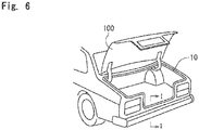
Fig. 6 , aweather strip 10 is operatively coupled on the body of the automobile at the peripheral edge of the opening corresponding to theback door 100. Theweather strip 10 makes an elastic contact with theback door 100 when theback door 100 is closed. - As shown in
Fig. 7 , theweather strip 10 includes aninstallation base member 11 and ahollow seal member 12 integrally molded with theinstallation base member 11. Theinstallation base member 11 has a substantially U-shape cross section provided with an opening and is inserted over aflange 101 from a side of the opening. Theflange 101 is formed along a periphery-edges of the opening corresponding to theback door 100. Thehollow seal member 12 is provided to aninner wall 11c of theinstallation base member 11 and is arranged to elastically contact theback door 100 to thereby seal the inner-cabin side of the automobile from the outer-cabin side thereof. - The
installation base member 11 includes afirst side wall 11a, asecond side wall 11b and a plurality of protrudingpieces 13 provided to inner face of the first andsecond side walls protruding pieces 13 grab theflange 101. Thefirst side wall 11a is provided at tip end thereof with asmall lip 14 and at an outer side thereof with aseal lip 15. Thesecond side wall 11b is provided at an outer surface thereof with adecorative lip 16. A sponge or a butyl sealant is attached to an inner surface of theinner wall 11c of theinstallation base member 11. The sponge or the butyl sealant abuts and encloses a tip end of theflange 101 to thereby prevent corrosion of theflange 101 and intrusion of water. Acore material 18 made of metal or rigid resin is embedded in theinstallation base member 11 for reinforcement of theinstallation base member 11. - As shown in
Fig. 7 , in theweather strip 10 for the automobile configured as described above, whendirt 60 containing snow melting salt, for example, is stuck between thefirst side wall 11a positioned at an outer side of theinstallation base member 11 and theback door 100, anelectric circuit 80 is formed that circulates through theback door 100, theflange 101, theprotruding piece 13 provided to theinstallation base member 11, thefirst side wall 11a, thedirt 60 containing snow melting salt, and again theback door 100. - In addition, as shown in
Fig. 8 , if snow orwater 70 containing snow melting salt, for example, remains between thesecond side wall 11b positioned at an inner side of theinstallation base member 11 and thehollow seal member 12, anotherelectric circuit 90 is formed that circulates through theback door 100, the snow orwater 70, thedecorative lip 16, thesecond side wall 11b, theprotruding piece 13 provided to theinstallation base member 11, theflange 101 and again theback door 100. - Thus formed
electric circuits Fig. 7 ) and the portion 120 (Fig. 8 ) of theback door 100, through which an electricity flows, to be damaged, and the coatings of theportions back door 100 to be exposed, and resulting in a generation of corrosion and rust in theback door 100. - Besides the abovementioned configurations, there is a known weather strip for an automobile that includes a hollow seal member partially coated with an insulation layer. This configuration is disclosed in Japanese Unexamined Patent Application Publication No.
2001-509108 - Further weather strips are described in
US 2012/0240473A1 ,EP 1 457 376 A1US 2013/0067821 A1 , andEP 1 663 685 B1 - Unlike the present invention, the invention disclosed in the abovementioned patent publication is such that a rubber member that is electrically conductive and can be heated is used for a cover seal part and a wiper blade in order to melt frozen water. With this configuration, the insulation layer partially covering the cover seal part, etc. prevents an electrical shock of a user and a damage caused by corrosion.
- Specifically, the invention of the patent publication is designed to partially cover a member to be electrically conductive with an insulation layer. Such a configuration does not correspond to the configuration described with reference to
Figs. 7 and8 , in which theelectric circuits dirt 60 or the snow orwater 70 containing snow melting salt that is stuck or remains between theinstallation base member 11 and theback door 100 are shut down so as to prevent corrosion. In addition, the patent publication does not present such an attention or consideration, at all. - It is therefore an object of the present invention to provide a weather strip for an automobile, which weather strip is able to shut down an electric circuit that can be formed caused by an intrusion of snow, water, etc. to thereby effectively prevent generation of corrosion.
- In order to achieve the abovementioned object, according to the invention, a weather strip (10) for an automobile is provided, the weather strip (10) for the automobile comprising: an installation base member (11) to be operatively coupled on a body of an automobile at a periphery edge of an opening corresponding to a back door (100); and a hollow seal member (12) integrally molded with the installation base member (11), the hollow seal member (12) protruding from the installation base member (11) toward a side of the back door (100) at an outer-cabin side, the hollow seal member (12) making elastic contact with the back door (100) when the back door (100) is in a closed position, wherein
the hollow seal member (12) and the installation base member (11) continued from the hollow seal member (12) each have an exposed outer surface, an outer surface of the hollow seal member (12) being formed wholly by a non-electric conductive material, an outer surface of the installation base member (11) being formed partially or wholly by a non-electric conductive material (30), the two non-electric conductive materials (30) being sequentially continuous, the non-electric conductive materials (30) having the volume resistivity of 106 Qm or greater. - It should be noted that forming of an outer surface by a non-electric conductive material described above includes the case where an outer surface of the weather strip for the automobile is coated or covered with the non-electric conductive material that is materially different from the weather strip for the automobile, but does notinclude the case where the outer surface of the weather strip for the automobile is made of the non-electric conductive material without an application of the material that is materially different from the weather strip for the automobile.
- In addition, according to the invention, at least the outer surface of the hollow seal member (12) and the outer surface of a first side wall (11a) of the installation base member (11) are continuously formed by the non-electric conductive material (30), the first side wall (11a) being located at an outer side of the opening corresponding to the back door (100), the installation base member (11) being continued from the hollow seal member (12).
- In addition, according to the invention, the first side wall (11a) of the installation base member (11) is provided with a seal lip (15), the seal lip (15) protruding from the first side wall (11a) and making an elastic contact with an periphery edge portion of the opening corresponding to the back door (100), in which at least the outer surface of the hollow seal member (12) and an outer surface of the seal lip (15) are continuously formed by the non-electric conductive material (30).
- In addition, according to an aspect of the invention, at least the outer surface of the hollow seal member (12) and an outer surface of a second side wall (11b) of the installation base member (11) are continuously formed by the non-electric conductive material (30), the second side wall (11b) being the installation base member (11) being continued from the hollow seal member (12).
- In addition, according to an aspect of the invention, the second side wall (11b) of the installation base member (11) is provided with a decorative lip (16), the decorative lip (16) protruding from the second side wall (11b), in which the outer surface of the hollow seal member (12) and an outer surface of the decorative lip (16) are continuously formed by the non-electric conductive material (30).
- Symbols in parentheses show constituents or items corresponding to the drawings.
- It should be noted that the "outer-cabin side" refers to a side of the back door (100) when the back door (100) is in the closed position, and an "inner-cabin side" refers to a reversed side of the outer-cabin side. In addition, an "outer side" refers to a side farther from the location of the flange (101), on which the installation base member (11) is operatively coupled, in a direction away from an inner cabinet. An "inner side" refers to a reversed side of the outer side.
- According to the weather strip for the automobile in the present invention, the exposed outer surface of the hollow seal member is entirely, and not partially, formed by the non-electric conductive material, and the outer surface of the installation base member continued from the hollow seal member is formed partially or entirely by the non-electric conductive material that is continuous from the non-electric conductive material of the hollow seal member, in which the continuous non-electric conductive material has the volume resistivity of 106Ωcm or greater. In addition to this configuration, the outer surfaces of the hollow seal member and the first side wall of the installation base member located at the outer side of the opening corresponding to the door are continuously formed by the non-electric conductive material, whereby formation of an electric circuit at the outer side of the opening corresponding to the door is prevented. Furthermore, the outer surfaces of the hollow seal member and the second side wall of the installation base member located at the inner side of the opening corresponding to the door are continuously formed by the non-electric conductive material, whereby formation of an electric circuit at the inner side of the opening corresponding to the door is prevented. Moreover, the outer surfaces of the hollow seal member, the first side wall and the second side wall are continuously formed by the non-electric conductive material having the volume resistivity of 106 Qcm or greater, whereby formation of electric circuits at the outer side and the inner side of the opening corresponding to the door is prevented.
- Thus, even if dirt containing snow melting salt, for example, is stuck between the first side wall of the installation base member and the door, such an event does not allow a formation of the electric circuit there. Accordingly, the outer side of the door is prevented from any damage caused by electricity, a peeling off of a coating, and corrosion in the damaged area.
- In addition, dirt, snow or water containing snow melting salt, for example, stuck or remained between the second side wall and the door does not allow the formation of the electric circuit. This can also prevent any damage at the inner side of the door, the peeling off of the coating, and corrosion at the damaged area.
- It should be noted that the feature in which the outer surfaces of the hollow seal member and the installation base member are formed, for the purpose of insulation, by the non-electric conductive material having the volume resistivity of 106 Ωcm is not known or acknowledged conventionally.
-
-
Fig. 1 is an I-I line enlarged cross section ofFig. 6 showing a weather strip for an automobile according to an embodiment of the present invention; -
Fig. 2 is an I-I line enlarged cross section ofFig. 6 showing another weather strip for an automobile according to an embodiment of the present invention; -
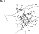
Fig. 3 is an I-I line enlarged cross section ofFig. 6 showing still another weather strip for an automobile according to an embodiment of the present invention; -
Fig. 4 is an I-I line enlarged cross section ofFig. 6 showing still another weather strip for an automobile according to an embodiment of the present invention; -
Fig. 5 is an I-I line enlarged cross section ofFig. 6 showing still another weather strip for an automobile according to an embodiment of the present invention; -
Fig. 6 is a perspective view showing an appearance of an automobile including a back door that is opened; -
Fig. 7 is an I-I line enlarged cross section ofFig. 6 showing a conventional weather strip for an automobile to which dirt containing snow melting salt is stuck; -
Fig. 8 is an I-I line enlarged cross section ofFig. 6 showing the conventional weather strip for the automobile ofFig. 7 on which water remains; and -
Fig. 9 is an I-I line enlarged cross section ofFig. 6 showing the weather strip for the automobile according to an embodiment of the present invention, the weather strip being subjected to an electric conductive test. - With reference to
Figs. 1 to 6 , aweather strip 10 for an automobile according to an embodiment of the present invention will be described. In theweather strip 10, parts or members identical to those of the prior art are provided with the same reference numerals. - As shown in
Fig. 6 , theweather strip 10 for the automobile includes aninstallation base member 11 and ahollow seal member 12. Theinstallation base member 11 is inserted over aflange 101 that is provided to a body of an automobile along a periphery-edge of an opening corresponding to aback door 100. Thehollow seal member 12 is integrally molded with theinstallation base member 11 at an outer-cabin side thereof and is making elastic contact with theback door 100, when theback door 100 is in a closed position, to thereby seal an inner-cabin side of the automobile from an outer-cabin side thereof. - It should be noted that the "outer-cabin side" refers to a side of the
back door 100 when theback door 100 is in the closed position, and an "inner-cabin side" refers to a reversed side of the outer-cabin side (the side of the flange 101). In addition, an "outer side" refers to a side farther from the location of theflange 101, on which theinstallation base member 11 is operatively coupled, in a direction away from an inner cabinet. An "inner side" refers to a reversed side of the outer side. - The
installation base member 11 includes afirst side wall 11a, asecond side wall 11b, and aninner wall 11c connecting thoseside walls installation base member 11 has a U-shape cross section. When theback door 100 is closed, thefirst side wall 11a becomes substantially perpendicular to a surface of theback door 100, with which thehollow seal member 12 makes an elastic contact, and is disposed at an outer side of the opening corresponding to theback door 100. Similarly, when theback door 100 is in a closed position, thesecond side wall 11b becomes substantially perpendicular to the surface of theback door 100, with which thehollow seal member 12 makes the elastic contact, and is disposed at an inner side of the opening corresponding to theback door 100. The first andsecond side walls second side walls installation base member 11 are provided with a plurality of protruding pieces 13 (four in total in this embodiment) that slidably contact the surface of theflange 101 in an insert mounting operation. In addition, thefirst side wall 11a is provided with asmall lip 14 at a tip end or the inner side thereof and aseal lip 15 at the outer side thereof. Thesecond side wall 11b is provided with adecorative lip 16 at the inner side thereof and at a location where thesecond side wall 11b is connected to theinner wall 11c. Thedecorative lip 16 has a generally tang-shape cross section. Acore member 18 is embedded in theinstallation base member 11. Thecore member 18 is made of metal or rigid resin and has a substantially U-shape cross section. A water-sealing sponge or abutyl sealant 17 is provided to an inner surface of theinner wall 11c of theinstallation base member 11 so as to contact and surrounds the tip end of theflange 101, thereby preventing corrosion of theflange 101 and inhibiting an intrusion of water. - The
hollow seal member 12 is connected to theinstallation base member 11 at the outer face of theinner wall 11c and extends toward the outer-cabin side. Thehollow seal member 12 has a substantially diamond-shape cross section, though the shape is not limited, and includes aprotruding part 12a that protrudes toward the outer-cabin side. Theprotruding part 12a is configured to initially contact theback door 100 when theback door 100 is in the closed position. It should be noted that theprotruding part 12a may be excluded. - An exposed outer surfaces of the
hollow seal member 12 and the continuousfirst side wall 11a including theseal lip 15 are all and continuously formed by a non-electricconductive material 30. InFig. 1 , although an outer surfaces of thehollow seal member 12 and thefirst side wall 11a continued from thehollow seal member 12 are viewed to be covered or coated by thenon-electric material 30, the outer surfaces in said area may according to the invention not be made of the non-electricconductive material 30, instead the outer surfaces of said area being covered or coated by thenon-electric material 30. Specifically, if thehollow seal member 12 is made of a sponge material or thermoplastic elastomer, for example, the outer surface of thehollow seal member 12 is considered to be made of the non-electricconductive material 30, without an additional material covering or coating the outer surface of thehollow seal member 12. This configuration can be applied in the same manner to theseal lip 15, theinstallation base member 11 and thedecorative lip 16. - The
non-electric material 30 may be made of a material having the volume resistivity of 106 Ωm or greater, and the material used in this embodiment has the volume resistivity of 107 Ωm, upon consideration of a variation in the material. - The material of the non-electric
conductive material 30 includes a rubber material such as an EPDM made sponge rubber material, a rubber material such as an EPDM made solid rubber material, and a resin material such as olefin base (TPO) or styrene base (TPS) thermoplastic elastomer (TPE). - When the EPDM made solid rubber is used, the electric resistance can be adjusted by selectively choosing the type or amount of carbon black that is normally added to improve the strength, rigidity and weather resistance of the rubber. The EPDM made sponge material, if used, can include many air bubbles and thus is provided with the electric resistance that is smaller than that of the solid rubber material. It is noted that the electric resistance can be adjusted by the size or amount of the air bubbles.
- If the type of the non-electric
conductive material 30 to be used is a coating film, the film should have a thickness of 0.05 mm or greater, preferably 0.1 mm or greater, and more preferably 0.2 mm or greater. In addition, the film may preferably have the thickness of 1 mm or smaller, and more preferably 0.5 mm. - According to the
weather strip 10 for the automobile provided with the abovementioned configuration, the non-electricconductive material 30 having the volume resistivity of 106 Qcm or greater continuously and wholly covers the exposed outer surfaces of thehollow seal member 12 and theinstallation base member 11 continued from thehollow seal member 12. Thus, the continuously covered area from thehollow seal member 12 to thefirst side wall 11a of theinstallation base member 11 prevents a formation of an electric circuit at the outer side of the opening corresponding to theback door 100. In addition, the continuously covered area from thehollow seal member 12 to thesecond side wall 11b of theinstallation base member 11 prevents a formation of the electric circuit at the inner side of the opening corresponding to theback door 100. - Thus, even if
dirt 60 containing snow melting salt, for example, is stuck between thefirst side wall 11a of theinstallation base member 11 and theback door 100, this configuration successfully prevents a formation of an electric circuit 80 (seeFig. 7 ), and thereby preventing a damage of theback door 100 at the outer side thereof caused by electricity, which damage can otherwise lead to a peeling off of the coating and corrosion of the damaged area. - In addition, this configuration also prevents a formation of an electric circuit 90 (see
Fig. 8 ), even if snow or water containing snow melting salt remains between thesecond side wall 11b of theinstallation base member 11 and theback door 100, thereby preventing a damage of theback door 100 at the inner side thereof caused by electricity, which damage can otherwise lead to the peeling off of the coating and corrosion of the damaged area. - In the embodiment shown in
Fig. 1 , the non-electricconductive material 30 continuously forms the outer surface of thehollow seal member 12 and an outer surface of thefirst side wall 11a of theinstallation base member 11 continued from thehollow seal member 12, and additionally forms the outer surface of thehollow seal member 12 and an outer surface of thesecond side wall 11b of theinstallation base member 11 continued from thehollow seal member 12. Alternatively, as shown inFig. 2 , the non-electricconductive material 30 is allowed to continuously form only the outer surface of thehollow seal member 12 and the outer surface of thefirst side wall 11a of theinstallation base member 11 continued from thehollow seal member 12, in order to prevent a formation of the electric circuit 80 (seeFig. 7 ). Conversely, as shown inFig. 3 , the non-electricconductive material 30 is allowed to continuously form only the outer surface of thehollow seal member 12 and the outer surface of thesecond side wall 11b of theinstallation base member 11 continued from thehollow seal member 12, in order to prevent the formation of the electric circuit 90 (seeFig. 8 ). In these figures, the non-electricconductive material 30 is coated. Coating of the non-electricconductive material 30, however, is unneeded for an outer surface that is made of the non-electricconductive material 30. - In addition, as shown in
Fig. 4 , the non-electricconductive material 30 may continuously form (coated in the figure) the outer surface of thehollow seal member 12 and the outer surface of thefirst side wall 11a of theinstallation base member 11 and further forms the exposed entire outer surface of theseal lip 15. Furthermore, the non-electricconductive material 30 may form (coated in the figure) the exposed entire outer surface of the multiple protrudingpieces 13 provided to an inner face of theinstallation base member 11. - Moreover, for one type of the
installation base member 11 shown inFig. 5 , which is not provided with theseal lip 15 and thedecorative lip 16, the non-electricconductive material 30 may be allowed to form (coated in the figure), in a surrounding manner, the outer surfaces of the first andsecond side walls - The configuration of forming the outer surfaces by the non-electric
conductive material 30 may be considered that the non-electricconductive material 30 of a different or independent material from theweather strip 10 for the automobile is additionally coated on an outer surfaces of theweather strip 10 for the automobile, as viewed in the embodiments shown inFigs. 1 to 5 . Instead, in the case where thehollow seal member 12, theinstallation base member 11, theseal lip 15 or thedecorative lip 16 of the weather strip for the automobile are made of a material having the volume resistivity of 106 Qcm or greater, coating of a material different from the material of these members is unneeded. In addition, such a configuration may be considered that the outer surfaces of these members are coated with the non-electricconductive material 30. - This embodiment discloses the
weather strip 10 for the automobile that is operatively coupled on the body of the automobile at the periphery edge of the opening corresponding to theback door 100, in which theweather strip 10 for the automobile is arranged to make the elastic contact with theback door 100. Alternatively, the present invention can be applied for other types of doors such as a laterally openable door and an openable/closable door provided to a roof and other locations. Furthermore, the present invention can also be applied for a slide door provided to a side surface of an automobile body. - An electric conductive test was carried out using the
weather strip 10 for the automobile shown inFig. 1 . -
Fig. 9 shows a structure of aweather strip 10 disposed at a trunk or back door located at a rear part of an automobile. Theweather strip 10 for the automobile includes aninstallation base member 11 of a substantially U-shape cross section, which is provided with a plurality of protrudingpieces 13 that make a slide contact with surface of a metal madeflange 101. Theweather strip 10 for the automobile includes aninstallation base member 11 of a substantially U-shape cross section, which is provided with a plurality of protrudingpieces 13 that make a slide contact with surface of a metal madeflange 101. Theweather strip 10 for the automobile also includes asecond side wall 11b, aninner wall 11c and adecorative lip 16 which is provided at a location where thesecond side wall 11b is joined to theinner wall 11c and has a substantially tang-shape cross section. Theinstallation base member 11, the plurality of protrudingpieces 13 and thedecorative lip 16 are made of a solid rubber material of an EPDM polymer in which carbon black is added. A metal madecore member 18 having a substantially U-shape cross section is embedded in theinstallation base member 11. Theweather strip 10 for the automobile also includes ahollow seal member 12 having a substantially diamond-shape cross section, which hollowseal member 12 is connected to theinstallation base member 11 at an outer face of theinner wall 11c and is directed toward an outer-cabin side. Theweather strip 10 for the automobile further includes afirst side wall 11a, asmall lip 14 at an inner tip end side of thefirst side wall 11a, and aseal lip 15 at an outer side of thefirst side wall 11a. Thehollow seal member 12, thesmall lip 14 and theseal lip 15 are made of a sponge material composed of an EPDM polymer added with carbon black, and has the specific gravity of about 0.5. - The outer surface extending from the
hollow seal member 12 to theseal lip 15 is covered with a sponge rubber material that is the same as the material of thehollow seal member 12 and theseal lip 15. The sponge rubber material has a thickness of 0.3 mm. - One terminal 50A of a
tester 50 is contacted to an outer surface of theinstallation base member 11 that is located between thehollow seal member 12 and theseal lip 15 and is covered with the sponge rubber material, while the other terminal 50B of thetester 50 is contacted to a metal made panel extending from theflange 101. Then, 500V is applied between the twoterminals - Meanwhile, in a comparative example where the
installation base member 11 extending from thehollow seal member 12 to aseal lip 15 is not covered with a sponge material and thus has an exposed solid material, the tester indicated between 0.8×10⁴ Qcm and 1.5×10⁴ Ωcm.
Claims (3)
- A weather strip (10) for an automobile comprising: an installation base member (11) to be operatively coupled on a flange, the flange being provided to a body of the automobile at a periphery edge of an opening corresponding to a door; and a hollow seal member (12) integrally molded with the installation base member (11), the hollow seal member (12) protruding from the installation base member (11) toward a side of the door at an outer-cabin side, the hollow seal member (12) making elastic contact with the door when the door is in a closed position, wherein
the hollow seal member (12) and the installation base member (11) continued from the hollow seal member each have an exposed outer surface, an outer surface of the hollow seal member (12) being formed wholly by a non-electric conductive material, an outer surface of the installation base member (11) being formed partially or wholly by the non-electric conductive material (30), the two non-electric conductive materials (30) being sequentially continuous, the non-electric conductive materials (30) having the volume resistivity of 106 Qcm or greater,
wherein at least the outer surface of the hollow seal member (12) and an outer surface of a first side wall (11a) of the installation base member (11) are continuously formed by the non-electric conductive material (30), the first side wall (11a) being located at an outer side of the opening corresponding to the door, the installation base member (11) being continued from the hollow seal member (12), characterized in that
the first side wall (11a) of the installation base member (11) is provided with a seal lip (15), the seal lip (15) protruding from the first side wall (11a) and making an elastic contact with the periphery edge of the opening corresponding to the door, wherein the hollow seal member (12) and the seal lip (15) are made of a sponge material composed of an EPDM polymer added with carbon black, and in which at least the outer surface of the hollow seal member (12) and an outer surface of the seal lip (15) are continuously formed by the non-electric conductive material (30), wherein the outer surface extending from the hollow seal member (12) to the seal lip (15) is covered with a sponge material that is the same as the material of the hollow seal member (12) and the seal lip (15). - The weather strip for the automobile as claimed in claim 1, wherein at least the outer surface of the hollow seal member (12) and an outer surface of a second side wall (11b) of the installation base member (11) are continuously formed by the non-electric conductive material (30), the second side wall (11b) being located at an inner side of the opening corresponding to the door, the installation base member (11) being continued from the hollow seal member (12).
- The weather strip for the automobile as claimed in claim 2, wherein the second side wall (11b) of the installation base member (11) is provided with a decorative lip (16), the decorative lip (16) protruding from the second side wall (11b), and wherein the outer surface of the hollow seal member (12) and an outer surface of the decorative lip (16) are continuously formed by the non-electric conductive material (30).
Applications Claiming Priority (1)
| Application Number | Priority Date | Filing Date | Title |
|---|---|---|---|
| JP2015146412A JP2017024612A (en) | 2015-07-24 | 2015-07-24 | Automotive weatherstrip |
Publications (2)
| Publication Number | Publication Date |
|---|---|
| EP3121044A1 EP3121044A1 (en) | 2017-01-25 |
| EP3121044B1 true EP3121044B1 (en) | 2019-11-27 |
Family
ID=56464061
Family Applications (1)
| Application Number | Title | Priority Date | Filing Date |
|---|---|---|---|
| EP16179771.7A Active EP3121044B1 (en) | 2015-07-24 | 2016-07-15 | Weather strip for automobile |
Country Status (4)
| Country | Link |
|---|---|
| US (1) | US9994095B2 (en) |
| EP (1) | EP3121044B1 (en) |
| JP (1) | JP2017024612A (en) |
| CN (1) | CN106364293A (en) |
Families Citing this family (10)
| Publication number | Priority date | Publication date | Assignee | Title |
|---|---|---|---|---|
| JP7097190B2 (en) * | 2018-02-19 | 2022-07-07 | 西川ゴム工業株式会社 | Automotive weatherstrip |
| CN108928222A (en) * | 2018-08-17 | 2018-12-04 | 安徽奥丰汽车配件有限公司 | A kind of rubber vehicle press strip core |
| JP7086356B2 (en) * | 2019-01-25 | 2022-06-20 | 東海興業株式会社 | Trim material for vehicles |
| JP7689948B2 (en) | 2019-09-24 | 2025-06-09 | ダウ グローバル テクノロジーズ エルエルシー | Polymer Compositions for Extrusion Profiles |
| WO2021061578A1 (en) | 2019-09-24 | 2021-04-01 | Dow Global Technologies Llc | Polymer compositions with excellent electrical and mechanical properties |
| CN112721581A (en) * | 2019-10-29 | 2021-04-30 | 北京车和家信息技术有限公司 | Sealing strip, vehicle window glass heating device and method and vehicle |
| JP7475197B2 (en) * | 2020-05-15 | 2024-04-26 | 東海興業株式会社 | Joining sheet material for weather strips, weather strips and manufacturing method thereof |
| FR3127724B1 (en) * | 2021-10-01 | 2023-09-08 | Hutchinson | HEATED SEAL FOR A VEHICLE WINDOW |
| CN113997875B (en) * | 2021-11-05 | 2024-05-24 | 建新赵氏科技股份有限公司 | Novel electric automobile trunk clearance sealing strip structure |
| JP7780477B2 (en) * | 2023-07-03 | 2025-12-04 | 鬼怒川ゴム工業株式会社 | Automotive weather strips |
Family Cites Families (19)
| Publication number | Priority date | Publication date | Assignee | Title |
|---|---|---|---|---|
| DE19651733A1 (en) | 1996-12-12 | 1998-06-18 | Metzeler Automotive Profiles | Heated rubber body |
| TW466190B (en) * | 1999-07-23 | 2001-12-01 | Toyoda Gosei Kk | Weather resistant strip and process for manufacturing the same |
| US6849310B2 (en) * | 2001-04-20 | 2005-02-01 | Schlegel Corporation | Contiguous colliquefaction forming a surface film for a composite strip |
| FR2843077A1 (en) * | 2002-08-02 | 2004-02-06 | Hutchinson | Seal extrusion for sliding window of motor vehicle has fixing section of rigid thermoplastic material without reinforcement |
| US20050048263A1 (en) * | 2003-08-26 | 2005-03-03 | Schlegel Corporation | Reflective surface for a vehicle weatherseal |
| DE04772634T1 (en) * | 2003-09-17 | 2006-10-12 | Tokai Kogyo Co. Ltd., Obu | LONG PLAIN MEMBER AND METHOD OF MANUFACTURING THEREOF |
| FR2869969B1 (en) * | 2004-05-05 | 2006-08-04 | Metzeler Automotive Profile | IMPROVEMENTS IN SEAL GASKETS, IN PARTICULAR FOR MOTOR VEHICLES |
| US20060162257A1 (en) * | 2005-01-27 | 2006-07-27 | Toyoda Gosei Co., Ltd | Weather strip for motor vehicle |
| US8205391B2 (en) * | 2007-09-20 | 2012-06-26 | Toyoda Gosei Co., Ltd. | Automobile weather strip |
| JP4577791B2 (en) * | 2007-12-28 | 2010-11-10 | 東海興業株式会社 | Molded product and manufacturing method thereof |
| JP4974013B2 (en) * | 2009-07-28 | 2012-07-11 | トキワケミカル工業株式会社 | Extruded product with core material |
| JP2011126347A (en) * | 2009-12-16 | 2011-06-30 | Nishikawa Rubber Co Ltd | Weather strip |
| CN201970833U (en) * | 2010-12-27 | 2011-09-14 | 浙江吉利汽车有限公司 | Trunk sealing strip |
| US20120240473A1 (en) * | 2011-03-23 | 2012-09-27 | Toyoda Gosei Co., Ltd. | Weather strip and production method thereof |
| JP5556776B2 (en) * | 2011-09-21 | 2014-07-23 | 豊田合成株式会社 | Weather strip |
| CN202242907U (en) * | 2011-09-30 | 2012-05-30 | 浙江兴宇汽车零部件有限公司 | Car back door frame seal strip |
| CN202863104U (en) * | 2012-10-11 | 2013-04-10 | 浙江吉利汽车有限公司 | Car window outer side sealing strip |
| JP6228166B2 (en) * | 2015-07-03 | 2017-11-08 | 西川ゴム工業株式会社 | Automotive weatherstrip |
| JP6694721B2 (en) * | 2016-02-10 | 2020-05-20 | 西川ゴム工業株式会社 | Weather Strip |
-
2015
- 2015-07-24 JP JP2015146412A patent/JP2017024612A/en active Pending
-
2016
- 2016-07-15 EP EP16179771.7A patent/EP3121044B1/en active Active
- 2016-07-18 US US15/212,732 patent/US9994095B2/en active Active
- 2016-07-19 CN CN201610567309.8A patent/CN106364293A/en not_active Withdrawn
Non-Patent Citations (1)
| Title |
|---|
| None * |
Also Published As
| Publication number | Publication date |
|---|---|
| US20170021707A1 (en) | 2017-01-26 |
| US9994095B2 (en) | 2018-06-12 |
| JP2017024612A (en) | 2017-02-02 |
| EP3121044A1 (en) | 2017-01-25 |
| CN106364293A (en) | 2017-02-01 |
Similar Documents
| Publication | Publication Date | Title |
|---|---|---|
| US9994095B2 (en) | Weather strip for automobile | |
| JP5932461B2 (en) | Vehicle trim | |
| CZ199493A3 (en) | Clamping safeguarding of mechanically controlled closing device | |
| US9656539B2 (en) | Belt molding for vehicle | |
| US11877357B2 (en) | Body part element comprising a heating film | |
| JP2008132864A (en) | Weather strip for automobile | |
| US8952280B2 (en) | Switch case having flanges that fold over clearance between case and cover | |
| CN105203134A (en) | Variably usable sensor unit | |
| JP2006327475A (en) | Plate member with frame | |
| US9010850B2 (en) | Weatherstrip for vehicle roof | |
| JP5568795B2 (en) | Weather strip for automobile | |
| JP2009149180A (en) | Weather strip | |
| JP2011024280A (en) | Sealing member and method of manufacturing the same | |
| JP2009107470A (en) | Opening trim weather strip | |
| CN112297804A (en) | Hidden outer water bar of side window and have its vehicle | |
| JP2010030445A (en) | Opening trim weather strip | |
| JP3517348B2 (en) | Water stop structure of the mounting part of the circuit body for car door | |
| JP4703407B2 (en) | Automotive molded body equipped with a pinch detection sensor | |
| JP6573159B2 (en) | Front panel seal structure | |
| JP2009083742A (en) | Insert panel embedded weatherstrip and manufacturing method thereof | |
| US20240359662A1 (en) | Vehicle wheel well component with heater | |
| JP6459909B2 (en) | Door side fixing part and wire harness | |
| JP2020107598A (en) | Sensor unit and fixing method thereof | |
| JP6520001B2 (en) | Structure of interior member | |
| JPH07205657A (en) | Sealing body for automobile door |
Legal Events
| Date | Code | Title | Description |
|---|---|---|---|
| PUAI | Public reference made under article 153(3) epc to a published international application that has entered the european phase |
Free format text: ORIGINAL CODE: 0009012 |
|
| STAA | Information on the status of an ep patent application or granted ep patent |
Free format text: STATUS: THE APPLICATION HAS BEEN PUBLISHED |
|
| AK | Designated contracting states |
Kind code of ref document: A1 Designated state(s): AL AT BE BG CH CY CZ DE DK EE ES FI FR GB GR HR HU IE IS IT LI LT LU LV MC MK MT NL NO PL PT RO RS SE SI SK SM TR |
|
| AX | Request for extension of the european patent |
Extension state: BA ME |
|
| STAA | Information on the status of an ep patent application or granted ep patent |
Free format text: STATUS: REQUEST FOR EXAMINATION WAS MADE |
|
| 17P | Request for examination filed |
Effective date: 20170725 |
|
| RBV | Designated contracting states (corrected) |
Designated state(s): AL AT BE BG CH CY CZ DE DK EE ES FI FR GB GR HR HU IE IS IT LI LT LU LV MC MK MT NL NO PL PT RO RS SE SI SK SM TR |
|
| STAA | Information on the status of an ep patent application or granted ep patent |
Free format text: STATUS: EXAMINATION IS IN PROGRESS |
|
| 17Q | First examination report despatched |
Effective date: 20180326 |
|
| RIC1 | Information provided on ipc code assigned before grant |
Ipc: B60J 10/32 20160101ALI20190712BHEP Ipc: B60J 10/24 20160101ALI20190712BHEP Ipc: B60J 10/16 20160101ALI20190712BHEP Ipc: B60J 10/84 20160101AFI20190712BHEP Ipc: B60R 13/06 20060101ALI20190712BHEP Ipc: B60J 10/15 20160101ALI20190712BHEP |
|
| GRAP | Despatch of communication of intention to grant a patent |
Free format text: ORIGINAL CODE: EPIDOSNIGR1 |
|
| STAA | Information on the status of an ep patent application or granted ep patent |
Free format text: STATUS: GRANT OF PATENT IS INTENDED |
|
| RAP1 | Party data changed (applicant data changed or rights of an application transferred) |
Owner name: NISHIKAWA RUBBER CO., LTD. |
|
| INTG | Intention to grant announced |
Effective date: 20190909 |
|
| GRAS | Grant fee paid |
Free format text: ORIGINAL CODE: EPIDOSNIGR3 |
|
| GRAA | (expected) grant |
Free format text: ORIGINAL CODE: 0009210 |
|
| STAA | Information on the status of an ep patent application or granted ep patent |
Free format text: STATUS: THE PATENT HAS BEEN GRANTED |
|
| AK | Designated contracting states |
Kind code of ref document: B1 Designated state(s): AL AT BE BG CH CY CZ DE DK EE ES FI FR GB GR HR HU IE IS IT LI LT LU LV MC MK MT NL NO PL PT RO RS SE SI SK SM TR |
|
| REG | Reference to a national code |
Ref country code: GB Ref legal event code: FG4D |
|
| REG | Reference to a national code |
Ref country code: CH Ref legal event code: EP |
|
| REG | Reference to a national code |
Ref country code: AT Ref legal event code: REF Ref document number: 1206255 Country of ref document: AT Kind code of ref document: T Effective date: 20191215 |
|
| REG | Reference to a national code |
Ref country code: DE Ref legal event code: R096 Ref document number: 602016024952 Country of ref document: DE |
|
| REG | Reference to a national code |
Ref country code: IE Ref legal event code: FG4D |
|
| REG | Reference to a national code |
Ref country code: NL Ref legal event code: MP Effective date: 20191127 |
|
| REG | Reference to a national code |
Ref country code: LT Ref legal event code: MG4D |
|
| PG25 | Lapsed in a contracting state [announced via postgrant information from national office to epo] |
Ref country code: FI Free format text: LAPSE BECAUSE OF FAILURE TO SUBMIT A TRANSLATION OF THE DESCRIPTION OR TO PAY THE FEE WITHIN THE PRESCRIBED TIME-LIMIT Effective date: 20191127 Ref country code: BG Free format text: LAPSE BECAUSE OF FAILURE TO SUBMIT A TRANSLATION OF THE DESCRIPTION OR TO PAY THE FEE WITHIN THE PRESCRIBED TIME-LIMIT Effective date: 20200227 Ref country code: NO Free format text: LAPSE BECAUSE OF FAILURE TO SUBMIT A TRANSLATION OF THE DESCRIPTION OR TO PAY THE FEE WITHIN THE PRESCRIBED TIME-LIMIT Effective date: 20200227 Ref country code: LT Free format text: LAPSE BECAUSE OF FAILURE TO SUBMIT A TRANSLATION OF THE DESCRIPTION OR TO PAY THE FEE WITHIN THE PRESCRIBED TIME-LIMIT Effective date: 20191127 Ref country code: GR Free format text: LAPSE BECAUSE OF FAILURE TO SUBMIT A TRANSLATION OF THE DESCRIPTION OR TO PAY THE FEE WITHIN THE PRESCRIBED TIME-LIMIT Effective date: 20200228 Ref country code: SE Free format text: LAPSE BECAUSE OF FAILURE TO SUBMIT A TRANSLATION OF THE DESCRIPTION OR TO PAY THE FEE WITHIN THE PRESCRIBED TIME-LIMIT Effective date: 20191127 Ref country code: LV Free format text: LAPSE BECAUSE OF FAILURE TO SUBMIT A TRANSLATION OF THE DESCRIPTION OR TO PAY THE FEE WITHIN THE PRESCRIBED TIME-LIMIT Effective date: 20191127 Ref country code: NL Free format text: LAPSE BECAUSE OF FAILURE TO SUBMIT A TRANSLATION OF THE DESCRIPTION OR TO PAY THE FEE WITHIN THE PRESCRIBED TIME-LIMIT Effective date: 20191127 |
|
| PG25 | Lapsed in a contracting state [announced via postgrant information from national office to epo] |
Ref country code: HR Free format text: LAPSE BECAUSE OF FAILURE TO SUBMIT A TRANSLATION OF THE DESCRIPTION OR TO PAY THE FEE WITHIN THE PRESCRIBED TIME-LIMIT Effective date: 20191127 Ref country code: RS Free format text: LAPSE BECAUSE OF FAILURE TO SUBMIT A TRANSLATION OF THE DESCRIPTION OR TO PAY THE FEE WITHIN THE PRESCRIBED TIME-LIMIT Effective date: 20191127 Ref country code: IS Free format text: LAPSE BECAUSE OF FAILURE TO SUBMIT A TRANSLATION OF THE DESCRIPTION OR TO PAY THE FEE WITHIN THE PRESCRIBED TIME-LIMIT Effective date: 20200327 |
|
| PG25 | Lapsed in a contracting state [announced via postgrant information from national office to epo] |
Ref country code: AL Free format text: LAPSE BECAUSE OF FAILURE TO SUBMIT A TRANSLATION OF THE DESCRIPTION OR TO PAY THE FEE WITHIN THE PRESCRIBED TIME-LIMIT Effective date: 20191127 |
|
| PG25 | Lapsed in a contracting state [announced via postgrant information from national office to epo] |
Ref country code: DK Free format text: LAPSE BECAUSE OF FAILURE TO SUBMIT A TRANSLATION OF THE DESCRIPTION OR TO PAY THE FEE WITHIN THE PRESCRIBED TIME-LIMIT Effective date: 20191127 Ref country code: EE Free format text: LAPSE BECAUSE OF FAILURE TO SUBMIT A TRANSLATION OF THE DESCRIPTION OR TO PAY THE FEE WITHIN THE PRESCRIBED TIME-LIMIT Effective date: 20191127 Ref country code: PT Free format text: LAPSE BECAUSE OF FAILURE TO SUBMIT A TRANSLATION OF THE DESCRIPTION OR TO PAY THE FEE WITHIN THE PRESCRIBED TIME-LIMIT Effective date: 20200419 Ref country code: RO Free format text: LAPSE BECAUSE OF FAILURE TO SUBMIT A TRANSLATION OF THE DESCRIPTION OR TO PAY THE FEE WITHIN THE PRESCRIBED TIME-LIMIT Effective date: 20191127 Ref country code: CZ Free format text: LAPSE BECAUSE OF FAILURE TO SUBMIT A TRANSLATION OF THE DESCRIPTION OR TO PAY THE FEE WITHIN THE PRESCRIBED TIME-LIMIT Effective date: 20191127 Ref country code: ES Free format text: LAPSE BECAUSE OF FAILURE TO SUBMIT A TRANSLATION OF THE DESCRIPTION OR TO PAY THE FEE WITHIN THE PRESCRIBED TIME-LIMIT Effective date: 20191127 |
|
| REG | Reference to a national code |
Ref country code: DE Ref legal event code: R097 Ref document number: 602016024952 Country of ref document: DE |
|
| PG25 | Lapsed in a contracting state [announced via postgrant information from national office to epo] |
Ref country code: SM Free format text: LAPSE BECAUSE OF FAILURE TO SUBMIT A TRANSLATION OF THE DESCRIPTION OR TO PAY THE FEE WITHIN THE PRESCRIBED TIME-LIMIT Effective date: 20191127 Ref country code: SK Free format text: LAPSE BECAUSE OF FAILURE TO SUBMIT A TRANSLATION OF THE DESCRIPTION OR TO PAY THE FEE WITHIN THE PRESCRIBED TIME-LIMIT Effective date: 20191127 |
|
| REG | Reference to a national code |
Ref country code: AT Ref legal event code: MK05 Ref document number: 1206255 Country of ref document: AT Kind code of ref document: T Effective date: 20191127 |
|
| PLBE | No opposition filed within time limit |
Free format text: ORIGINAL CODE: 0009261 |
|
| STAA | Information on the status of an ep patent application or granted ep patent |
Free format text: STATUS: NO OPPOSITION FILED WITHIN TIME LIMIT |
|
| 26N | No opposition filed |
Effective date: 20200828 |
|
| PG25 | Lapsed in a contracting state [announced via postgrant information from national office to epo] |
Ref country code: PL Free format text: LAPSE BECAUSE OF FAILURE TO SUBMIT A TRANSLATION OF THE DESCRIPTION OR TO PAY THE FEE WITHIN THE PRESCRIBED TIME-LIMIT Effective date: 20191127 Ref country code: SI Free format text: LAPSE BECAUSE OF FAILURE TO SUBMIT A TRANSLATION OF THE DESCRIPTION OR TO PAY THE FEE WITHIN THE PRESCRIBED TIME-LIMIT Effective date: 20191127 Ref country code: AT Free format text: LAPSE BECAUSE OF FAILURE TO SUBMIT A TRANSLATION OF THE DESCRIPTION OR TO PAY THE FEE WITHIN THE PRESCRIBED TIME-LIMIT Effective date: 20191127 |
|
| PG25 | Lapsed in a contracting state [announced via postgrant information from national office to epo] |
Ref country code: IT Free format text: LAPSE BECAUSE OF FAILURE TO SUBMIT A TRANSLATION OF THE DESCRIPTION OR TO PAY THE FEE WITHIN THE PRESCRIBED TIME-LIMIT Effective date: 20191127 |
|
| PG25 | Lapsed in a contracting state [announced via postgrant information from national office to epo] |
Ref country code: MC Free format text: LAPSE BECAUSE OF FAILURE TO SUBMIT A TRANSLATION OF THE DESCRIPTION OR TO PAY THE FEE WITHIN THE PRESCRIBED TIME-LIMIT Effective date: 20191127 |
|
| REG | Reference to a national code |
Ref country code: CH Ref legal event code: PL |
|
| GBPC | Gb: european patent ceased through non-payment of renewal fee |
Effective date: 20200715 |
|
| REG | Reference to a national code |
Ref country code: BE Ref legal event code: MM Effective date: 20200731 |
|
| PG25 | Lapsed in a contracting state [announced via postgrant information from national office to epo] |
Ref country code: GB Free format text: LAPSE BECAUSE OF NON-PAYMENT OF DUE FEES Effective date: 20200715 Ref country code: FR Free format text: LAPSE BECAUSE OF NON-PAYMENT OF DUE FEES Effective date: 20200731 Ref country code: LI Free format text: LAPSE BECAUSE OF NON-PAYMENT OF DUE FEES Effective date: 20200731 Ref country code: LU Free format text: LAPSE BECAUSE OF NON-PAYMENT OF DUE FEES Effective date: 20200715 Ref country code: CH Free format text: LAPSE BECAUSE OF NON-PAYMENT OF DUE FEES Effective date: 20200731 |
|
| PG25 | Lapsed in a contracting state [announced via postgrant information from national office to epo] |
Ref country code: BE Free format text: LAPSE BECAUSE OF NON-PAYMENT OF DUE FEES Effective date: 20200731 |
|
| PG25 | Lapsed in a contracting state [announced via postgrant information from national office to epo] |
Ref country code: IE Free format text: LAPSE BECAUSE OF NON-PAYMENT OF DUE FEES Effective date: 20200715 |
|
| PG25 | Lapsed in a contracting state [announced via postgrant information from national office to epo] |
Ref country code: TR Free format text: LAPSE BECAUSE OF FAILURE TO SUBMIT A TRANSLATION OF THE DESCRIPTION OR TO PAY THE FEE WITHIN THE PRESCRIBED TIME-LIMIT Effective date: 20191127 Ref country code: MT Free format text: LAPSE BECAUSE OF FAILURE TO SUBMIT A TRANSLATION OF THE DESCRIPTION OR TO PAY THE FEE WITHIN THE PRESCRIBED TIME-LIMIT Effective date: 20191127 Ref country code: CY Free format text: LAPSE BECAUSE OF FAILURE TO SUBMIT A TRANSLATION OF THE DESCRIPTION OR TO PAY THE FEE WITHIN THE PRESCRIBED TIME-LIMIT Effective date: 20191127 |
|
| PG25 | Lapsed in a contracting state [announced via postgrant information from national office to epo] |
Ref country code: MK Free format text: LAPSE BECAUSE OF FAILURE TO SUBMIT A TRANSLATION OF THE DESCRIPTION OR TO PAY THE FEE WITHIN THE PRESCRIBED TIME-LIMIT Effective date: 20191127 |
|
| PGFP | Annual fee paid to national office [announced via postgrant information from national office to epo] |
Ref country code: DE Payment date: 20250528 Year of fee payment: 10 |