EP3120824A2 - Frame module and motion assistance apparatus including the same - Google Patents
Frame module and motion assistance apparatus including the same Download PDFInfo
- Publication number
- EP3120824A2 EP3120824A2 EP16180189.9A EP16180189A EP3120824A2 EP 3120824 A2 EP3120824 A2 EP 3120824A2 EP 16180189 A EP16180189 A EP 16180189A EP 3120824 A2 EP3120824 A2 EP 3120824A2
- Authority
- EP
- European Patent Office
- Prior art keywords
- belt
- frame
- user
- reinforcement
- module
- Prior art date
- Legal status (The legal status is an assumption and is not a legal conclusion. Google has not performed a legal analysis and makes no representation as to the accuracy of the status listed.)
- Granted
Links
- 230000033001 locomotion Effects 0.000 title claims description 41
- 230000002787 reinforcement Effects 0.000 claims abstract description 104
- 210000000689 upper leg Anatomy 0.000 claims description 16
- 210000000988 bone and bone Anatomy 0.000 claims description 15
- 210000004394 hip joint Anatomy 0.000 claims description 8
- 239000000463 material Substances 0.000 claims description 8
- 239000004744 fabric Substances 0.000 claims description 7
- 230000000712 assembly Effects 0.000 claims description 4
- 238000000429 assembly Methods 0.000 claims description 4
- 210000001624 hip Anatomy 0.000 description 21
- 238000009434 installation Methods 0.000 description 8
- 244000309466 calf Species 0.000 description 4
- AEUTYOVWOVBAKS-UWVGGRQHSA-N ethambutol Natural products CC[C@@H](CO)NCCN[C@@H](CC)CO AEUTYOVWOVBAKS-UWVGGRQHSA-N 0.000 description 3
- 230000003014 reinforcing effect Effects 0.000 description 3
- 230000037237 body shape Effects 0.000 description 2
- 210000002683 foot Anatomy 0.000 description 2
- 210000000629 knee joint Anatomy 0.000 description 2
- 238000012986 modification Methods 0.000 description 2
- 230000004048 modification Effects 0.000 description 2
- 210000003205 muscle Anatomy 0.000 description 2
- 210000004197 pelvis Anatomy 0.000 description 2
- 241001465754 Metazoa Species 0.000 description 1
- 230000032683 aging Effects 0.000 description 1
- 210000000544 articulatio talocruralis Anatomy 0.000 description 1
- 238000005452 bending Methods 0.000 description 1
- 230000009189 diving Effects 0.000 description 1
- 230000000694 effects Effects 0.000 description 1
- 210000003127 knee Anatomy 0.000 description 1
- 238000000034 method Methods 0.000 description 1
- 230000003387 muscular Effects 0.000 description 1
- 230000000644 propagated effect Effects 0.000 description 1
- 238000000926 separation method Methods 0.000 description 1
Images


Classifications
-
- A—HUMAN NECESSITIES
- A61—MEDICAL OR VETERINARY SCIENCE; HYGIENE
- A61H—PHYSICAL THERAPY APPARATUS, e.g. DEVICES FOR LOCATING OR STIMULATING REFLEX POINTS IN THE BODY; ARTIFICIAL RESPIRATION; MASSAGE; BATHING DEVICES FOR SPECIAL THERAPEUTIC OR HYGIENIC PURPOSES OR SPECIFIC PARTS OF THE BODY
- A61H1/00—Apparatus for passive exercising; Vibrating apparatus ; Chiropractic devices, e.g. body impacting devices, external devices for briefly extending or aligning unbroken bones
- A61H1/02—Stretching or bending or torsioning apparatus for exercising
- A61H1/0237—Stretching or bending or torsioning apparatus for exercising for the lower limbs
-
- A—HUMAN NECESSITIES
- A61—MEDICAL OR VETERINARY SCIENCE; HYGIENE
- A61F—FILTERS IMPLANTABLE INTO BLOOD VESSELS; PROSTHESES; DEVICES PROVIDING PATENCY TO, OR PREVENTING COLLAPSING OF, TUBULAR STRUCTURES OF THE BODY, e.g. STENTS; ORTHOPAEDIC, NURSING OR CONTRACEPTIVE DEVICES; FOMENTATION; TREATMENT OR PROTECTION OF EYES OR EARS; BANDAGES, DRESSINGS OR ABSORBENT PADS; FIRST-AID KITS
- A61F2/00—Filters implantable into blood vessels; Prostheses, i.e. artificial substitutes or replacements for parts of the body; Appliances for connecting them with the body; Devices providing patency to, or preventing collapsing of, tubular structures of the body, e.g. stents
- A61F2/50—Prostheses not implantable in the body
- A61F2/60—Artificial legs or feet or parts thereof
- A61F2/604—Joints for artificial legs
-
- A—HUMAN NECESSITIES
- A61—MEDICAL OR VETERINARY SCIENCE; HYGIENE
- A61F—FILTERS IMPLANTABLE INTO BLOOD VESSELS; PROSTHESES; DEVICES PROVIDING PATENCY TO, OR PREVENTING COLLAPSING OF, TUBULAR STRUCTURES OF THE BODY, e.g. STENTS; ORTHOPAEDIC, NURSING OR CONTRACEPTIVE DEVICES; FOMENTATION; TREATMENT OR PROTECTION OF EYES OR EARS; BANDAGES, DRESSINGS OR ABSORBENT PADS; FIRST-AID KITS
- A61F2/00—Filters implantable into blood vessels; Prostheses, i.e. artificial substitutes or replacements for parts of the body; Appliances for connecting them with the body; Devices providing patency to, or preventing collapsing of, tubular structures of the body, e.g. stents
- A61F2/50—Prostheses not implantable in the body
- A61F2/60—Artificial legs or feet or parts thereof
- A61F2/605—Hip joints
-
- A—HUMAN NECESSITIES
- A61—MEDICAL OR VETERINARY SCIENCE; HYGIENE
- A61F—FILTERS IMPLANTABLE INTO BLOOD VESSELS; PROSTHESES; DEVICES PROVIDING PATENCY TO, OR PREVENTING COLLAPSING OF, TUBULAR STRUCTURES OF THE BODY, e.g. STENTS; ORTHOPAEDIC, NURSING OR CONTRACEPTIVE DEVICES; FOMENTATION; TREATMENT OR PROTECTION OF EYES OR EARS; BANDAGES, DRESSINGS OR ABSORBENT PADS; FIRST-AID KITS
- A61F2/00—Filters implantable into blood vessels; Prostheses, i.e. artificial substitutes or replacements for parts of the body; Appliances for connecting them with the body; Devices providing patency to, or preventing collapsing of, tubular structures of the body, e.g. stents
- A61F2/50—Prostheses not implantable in the body
- A61F2/68—Operating or control means
- A61F2/70—Operating or control means electrical
-
- A—HUMAN NECESSITIES
- A61—MEDICAL OR VETERINARY SCIENCE; HYGIENE
- A61H—PHYSICAL THERAPY APPARATUS, e.g. DEVICES FOR LOCATING OR STIMULATING REFLEX POINTS IN THE BODY; ARTIFICIAL RESPIRATION; MASSAGE; BATHING DEVICES FOR SPECIAL THERAPEUTIC OR HYGIENIC PURPOSES OR SPECIFIC PARTS OF THE BODY
- A61H1/00—Apparatus for passive exercising; Vibrating apparatus ; Chiropractic devices, e.g. body impacting devices, external devices for briefly extending or aligning unbroken bones
- A61H1/02—Stretching or bending or torsioning apparatus for exercising
- A61H1/0214—Stretching or bending or torsioning apparatus for exercising by rotating cycling movement
-
- A—HUMAN NECESSITIES
- A61—MEDICAL OR VETERINARY SCIENCE; HYGIENE
- A61H—PHYSICAL THERAPY APPARATUS, e.g. DEVICES FOR LOCATING OR STIMULATING REFLEX POINTS IN THE BODY; ARTIFICIAL RESPIRATION; MASSAGE; BATHING DEVICES FOR SPECIAL THERAPEUTIC OR HYGIENIC PURPOSES OR SPECIFIC PARTS OF THE BODY
- A61H1/00—Apparatus for passive exercising; Vibrating apparatus ; Chiropractic devices, e.g. body impacting devices, external devices for briefly extending or aligning unbroken bones
- A61H1/02—Stretching or bending or torsioning apparatus for exercising
- A61H1/0237—Stretching or bending or torsioning apparatus for exercising for the lower limbs
- A61H1/0244—Hip
-
- A—HUMAN NECESSITIES
- A61—MEDICAL OR VETERINARY SCIENCE; HYGIENE
- A61H—PHYSICAL THERAPY APPARATUS, e.g. DEVICES FOR LOCATING OR STIMULATING REFLEX POINTS IN THE BODY; ARTIFICIAL RESPIRATION; MASSAGE; BATHING DEVICES FOR SPECIAL THERAPEUTIC OR HYGIENIC PURPOSES OR SPECIFIC PARTS OF THE BODY
- A61H1/00—Apparatus for passive exercising; Vibrating apparatus ; Chiropractic devices, e.g. body impacting devices, external devices for briefly extending or aligning unbroken bones
- A61H1/02—Stretching or bending or torsioning apparatus for exercising
- A61H1/0274—Stretching or bending or torsioning apparatus for exercising for the upper limbs
-
- A—HUMAN NECESSITIES
- A61—MEDICAL OR VETERINARY SCIENCE; HYGIENE
- A61H—PHYSICAL THERAPY APPARATUS, e.g. DEVICES FOR LOCATING OR STIMULATING REFLEX POINTS IN THE BODY; ARTIFICIAL RESPIRATION; MASSAGE; BATHING DEVICES FOR SPECIAL THERAPEUTIC OR HYGIENIC PURPOSES OR SPECIFIC PARTS OF THE BODY
- A61H3/00—Appliances for aiding patients or disabled persons to walk about
-
- A—HUMAN NECESSITIES
- A61—MEDICAL OR VETERINARY SCIENCE; HYGIENE
- A61F—FILTERS IMPLANTABLE INTO BLOOD VESSELS; PROSTHESES; DEVICES PROVIDING PATENCY TO, OR PREVENTING COLLAPSING OF, TUBULAR STRUCTURES OF THE BODY, e.g. STENTS; ORTHOPAEDIC, NURSING OR CONTRACEPTIVE DEVICES; FOMENTATION; TREATMENT OR PROTECTION OF EYES OR EARS; BANDAGES, DRESSINGS OR ABSORBENT PADS; FIRST-AID KITS
- A61F2/00—Filters implantable into blood vessels; Prostheses, i.e. artificial substitutes or replacements for parts of the body; Appliances for connecting them with the body; Devices providing patency to, or preventing collapsing of, tubular structures of the body, e.g. stents
- A61F2/50—Prostheses not implantable in the body
- A61F2/60—Artificial legs or feet or parts thereof
- A61F2002/608—Upper legs
-
- A—HUMAN NECESSITIES
- A61—MEDICAL OR VETERINARY SCIENCE; HYGIENE
- A61H—PHYSICAL THERAPY APPARATUS, e.g. DEVICES FOR LOCATING OR STIMULATING REFLEX POINTS IN THE BODY; ARTIFICIAL RESPIRATION; MASSAGE; BATHING DEVICES FOR SPECIAL THERAPEUTIC OR HYGIENIC PURPOSES OR SPECIFIC PARTS OF THE BODY
- A61H3/00—Appliances for aiding patients or disabled persons to walk about
- A61H2003/005—Appliances for aiding patients or disabled persons to walk about with knee, leg or stump rests
-
- A—HUMAN NECESSITIES
- A61—MEDICAL OR VETERINARY SCIENCE; HYGIENE
- A61H—PHYSICAL THERAPY APPARATUS, e.g. DEVICES FOR LOCATING OR STIMULATING REFLEX POINTS IN THE BODY; ARTIFICIAL RESPIRATION; MASSAGE; BATHING DEVICES FOR SPECIAL THERAPEUTIC OR HYGIENIC PURPOSES OR SPECIFIC PARTS OF THE BODY
- A61H3/00—Appliances for aiding patients or disabled persons to walk about
- A61H2003/007—Appliances for aiding patients or disabled persons to walk about secured to the patient, e.g. with belts
-
- A—HUMAN NECESSITIES
- A61—MEDICAL OR VETERINARY SCIENCE; HYGIENE
- A61H—PHYSICAL THERAPY APPARATUS, e.g. DEVICES FOR LOCATING OR STIMULATING REFLEX POINTS IN THE BODY; ARTIFICIAL RESPIRATION; MASSAGE; BATHING DEVICES FOR SPECIAL THERAPEUTIC OR HYGIENIC PURPOSES OR SPECIFIC PARTS OF THE BODY
- A61H2201/00—Characteristics of apparatus not provided for in the preceding codes
- A61H2201/12—Driving means
- A61H2201/1207—Driving means with electric or magnetic drive
-
- A—HUMAN NECESSITIES
- A61—MEDICAL OR VETERINARY SCIENCE; HYGIENE
- A61H—PHYSICAL THERAPY APPARATUS, e.g. DEVICES FOR LOCATING OR STIMULATING REFLEX POINTS IN THE BODY; ARTIFICIAL RESPIRATION; MASSAGE; BATHING DEVICES FOR SPECIAL THERAPEUTIC OR HYGIENIC PURPOSES OR SPECIFIC PARTS OF THE BODY
- A61H2201/00—Characteristics of apparatus not provided for in the preceding codes
- A61H2201/16—Physical interface with patient
- A61H2201/1602—Physical interface with patient kind of interface, e.g. head rest, knee support or lumbar support
- A61H2201/1628—Pelvis
- A61H2201/163—Pelvis holding means therefor
-
- A—HUMAN NECESSITIES
- A61—MEDICAL OR VETERINARY SCIENCE; HYGIENE
- A61H—PHYSICAL THERAPY APPARATUS, e.g. DEVICES FOR LOCATING OR STIMULATING REFLEX POINTS IN THE BODY; ARTIFICIAL RESPIRATION; MASSAGE; BATHING DEVICES FOR SPECIAL THERAPEUTIC OR HYGIENIC PURPOSES OR SPECIFIC PARTS OF THE BODY
- A61H2201/00—Characteristics of apparatus not provided for in the preceding codes
- A61H2201/16—Physical interface with patient
- A61H2201/1602—Physical interface with patient kind of interface, e.g. head rest, knee support or lumbar support
- A61H2201/164—Feet or leg, e.g. pedal
- A61H2201/1642—Holding means therefor
-
- A—HUMAN NECESSITIES
- A61—MEDICAL OR VETERINARY SCIENCE; HYGIENE
- A61H—PHYSICAL THERAPY APPARATUS, e.g. DEVICES FOR LOCATING OR STIMULATING REFLEX POINTS IN THE BODY; ARTIFICIAL RESPIRATION; MASSAGE; BATHING DEVICES FOR SPECIAL THERAPEUTIC OR HYGIENIC PURPOSES OR SPECIFIC PARTS OF THE BODY
- A61H2201/00—Characteristics of apparatus not provided for in the preceding codes
- A61H2201/16—Physical interface with patient
- A61H2201/1602—Physical interface with patient kind of interface, e.g. head rest, knee support or lumbar support
- A61H2201/165—Wearable interfaces
- A61H2201/1652—Harness
-
- A—HUMAN NECESSITIES
- A61—MEDICAL OR VETERINARY SCIENCE; HYGIENE
- A61H—PHYSICAL THERAPY APPARATUS, e.g. DEVICES FOR LOCATING OR STIMULATING REFLEX POINTS IN THE BODY; ARTIFICIAL RESPIRATION; MASSAGE; BATHING DEVICES FOR SPECIAL THERAPEUTIC OR HYGIENIC PURPOSES OR SPECIFIC PARTS OF THE BODY
- A61H2205/00—Devices for specific parts of the body
- A61H2205/06—Arms
-
- A—HUMAN NECESSITIES
- A61—MEDICAL OR VETERINARY SCIENCE; HYGIENE
- A61H—PHYSICAL THERAPY APPARATUS, e.g. DEVICES FOR LOCATING OR STIMULATING REFLEX POINTS IN THE BODY; ARTIFICIAL RESPIRATION; MASSAGE; BATHING DEVICES FOR SPECIAL THERAPEUTIC OR HYGIENIC PURPOSES OR SPECIFIC PARTS OF THE BODY
- A61H2205/00—Devices for specific parts of the body
- A61H2205/10—Leg
- A61H2205/106—Leg for the lower legs
-
- A—HUMAN NECESSITIES
- A61—MEDICAL OR VETERINARY SCIENCE; HYGIENE
- A61H—PHYSICAL THERAPY APPARATUS, e.g. DEVICES FOR LOCATING OR STIMULATING REFLEX POINTS IN THE BODY; ARTIFICIAL RESPIRATION; MASSAGE; BATHING DEVICES FOR SPECIAL THERAPEUTIC OR HYGIENIC PURPOSES OR SPECIFIC PARTS OF THE BODY
- A61H2205/00—Devices for specific parts of the body
- A61H2205/10—Leg
- A61H2205/108—Leg for the upper legs
Definitions
- At least one example embodiment relates to a frame module and/or a motion assistance apparatus including the same.
- motion assistance apparatuses enabling the elderly and/or patients having joint problems to walk with less effort. Furthermore, motion assistance apparatuses increasing muscular strength of human bodies are desired for military purposes.
- motion assistance apparatuses for assisting motion of lower parts of bodies may include body frames disposed on trunks of users, pelvic frames coupled to lower sides of the body frames to cover pelvises of the users, femoral frames disposed on thighs of the users, sural frames disposed on calves of the users, and/or pedial frames disposed on feet of the users.
- the pelvic frames and femoral frames may be connected rotatably by hip joint portions
- the femoral frames and sural frames may be connected rotatably by knee joint portions
- the sural frames and pedial frames may be connected rotatably by ankle joint portions.
- Some example embodiments relate to a frame module.
- the frame module may include a frame configured to enclose a portion of a user, and at least one reinforcement belt of which both end portions are connected to both sides of the frame, thereby restricting a splaying level and/or reinforcing the stiffness of the frame in a predetermined direction.
- the splaying level of the frame may include here the level of stretching or deformation of the frame.
- the at least one reinforcement belt may enhance the stiffness and softly enclose a body of a user at the same time, thereby increasing wearability Through this, the wearability of the frame module may increase for the user and the stiffness of the flexible waist frame may be enhanced without increasing the weight.
- a length of the reinforcement belt may be adjustable.
- the reinforcement belt may include a first sub-belt of which one end portion is connected to one side of the frame, and a second sub-belt of which one end portion is connected to another side of the frame. Another end portion of the first sub-belt may be detachable from another end portion of the second sub-belt.
- One end portion of at least one of the first sub-belt and the second sub-belt may be rotatably connected to the frame.
- the both end portions of the reinforcement belt may be connected to inner surfaces of the frame to support the user in a state in which the user is spaced apart from the frame.
- At least one of the both end portions of the reinforcement belt may be rotatably connected to the frame.
- a plurality of reinforcement belts may be provided, and the plurality of reinforcement belts may be connected to a single hinge axis provided in the frame.
- a plurality of reinforcement belts may be provided, and the plurality of reinforcement belts may be connected to each other to form a single closed loop.
- the frame may include a joint mounting portion in which a rotating member configured to be rotated by a driving module is to be installed, and the reinforcement belt may correspond to a joint belt of which one end portion is connected to one side of the joint mounting portion.
- the frame may include a supporting member configured to extend in a direction perpendicular to a circumferential direction of the portion of the user to support a body of the user, and the reinforcement belt may correspond to a supporting belt of which one end portion is connected to an end portion of the supporting member.
- the frame may include an upper supporting member and a lower supporting member configured to extend upward and downward in a direction perpendicular to a circumferential direction of the portion of the user, and the frame module may further include an upper supporting belt of which one end portion is connected to the upper supporting member, and a lower supporting belt of which one end portion is connected to the lower supporting member.
- the reinforcement belt may correspond to a crossing belt connected to the frame in a direction intersecting a circumferential direction of the portion of the user.
- the reinforcement belt may correspond to a parallel belt connected to the frame in a direction parallel to a circumferential direction of the portion of the user.
- the frame may include a joint mounting portion in which a rotating member configured to be rotated by a driving module is to be disposed, and a supporting member configured to extend in a direction perpendicular to a circumferential direction of the portion of the user to support a body of the user, and both end portions of the parallel belt may be connected to one side of the joint mounting portion and one side of the supporting member.
- the reinforcement belt may correspond to a bone belt disposed in a longitudinal direction of a bone of the user.
- the bone belt may correspond to an iliac crest belt disposed along an iliac crest of the user.
- the frame may include a joint mounting portion in which a rotating member configured to be rotated by a driving module is to be disposed.
- One side of the iliac crest belt may be connected to one side of the joint mounting portion, and another side of the iliac crest belt may be connected to a front portion of the frame.
- the frame may include an upper supporting member and a lower supporting member configured to extend upward and downward in a direction perpendicular to a circumferential direction of the portion of the user, and the reinforcement belt may correspond to a connecting belt configured to connect an end portion of the upper supporting member to an end portion of the lower supporting member.
- the frame may include a supporting member configured to extend in a direction perpendicular to a circumferential direction of the portion of the user to support a body of the user, and the reinforcement belt may correspond to a side belt of which one side is connected to the supporting member and another side is connected to a front portion of the frame.
- the frame module is a flexible waist wearing portion, for example a flexible waist wearing portion in a walking assist device.
- a motion assistance apparatus for example a walking assist device.
- the motion assistance apparatus may include a driving module configured to generate power to assist a motion of a user, a rotating member configured to be rotated by the driving module to assist a rotary motion of a joint portion of the user, and a frame module including a frame configured to enclose a portion of the user, the frame including a joint mounting portion in which the rotating member is to be disposed, and at least one reinforcement belt connected to both sides of the frame to reinforce a stiffness of the frame.
- the frame may further include a supporting member configured to extend in a direction perpendicular to a circumferential direction of the portion of the user to support a body of the user, and the reinforcement belt may include a joint belt of which one end portion is connected to one side of the joint mounting portion, and a supporting belt of which one end portion is connected to an end portion of the supporting member.
- Some example embodiments relate to a frame module.
- the frame module includes a plurality of interlocking frames configured to enclose a portion of a user; and at least one reinforcement belt configured to restrict a deformation of the plurality of interlocking frames in response to a torque applied thereto.
- the plurality of interlocking frames are flexible frames and are separated by an adjustable distance to secure the frame module onto the portion of the user, the plurality of interlocking frames configured to have joint assemblies mounted thereon, the joint assemblies configured to apply a torque to a support attached to at least a thigh of the user to assist the user with movement of their hip joints.
- the plurality of interlocking frames includes a first interlocking frame and a second interlocking frame
- the at least one reinforcement belt includes a first sub-belt and a second sub-belt connected to the first interlocking frame and the second interlocking frame, respectively, the first sub-belt configured to detach from the second sub-belt to allow the user to remove the frame module.
- the at least one reinforcement belt includes a plurality of reinforcement belts connected together in a closed loop.
- each of the plurality of reinforcement belts are connected to inner surfaces of the plurality of interlocking frames such that the at least one reinforcement belt is configured to maintain a gap between the plurality of interlocking frames and the user when the torque is applied to the plurality of interlocking frames.
- the reinforcement belt is made of a soft, light-weighted fabric material, for instance webbing belt or seat belt, so as to increase the comfort for the user.
- the soft, light-weighted fabric material of the reinforcement belt may include an essentially non-stretchable fabric so as to enable the reinforcement belt to provide the desired stiffness in the predetermined direction.
- the frame is a flexible frame. This may increase the wearability of the frame.
- the required stiffness of this flexible frame in one or more directions may be provided by an appropriate arrangement of the one of or more reinforcement belts.
- first, second, A, B, (a), (b), and the like may be used herein to describe components.
- Each of these terminologies is not used to define an essence, order or sequence of a corresponding component but used merely to distinguish the corresponding component from other component(s). It should be noted that if it is described in the specification that one component is “connected”, “coupled”, or “joined” to another component, a third component may be “connected”, “coupled”, and “joined” between the first and second components, although the first component may be directly connected, coupled or joined to the second component.
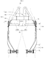
- FIG. 1 is a front view of a motion assistance apparatus according to at least one example embodiment
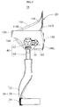
- FIG. 2 is a side view of a motion assistance apparatus according to at least one example embodiment.
- a motion assistance apparatus 10 may be worn by a user to assist a motion of the user.
- the user may correspond to a human, an animal, or a robot. However, the user is not limited thereto.
- FIG. 1 illustrates a case in which the motion assistance apparatus 10 assists the thighs of the user
- the motion assistance apparatus 10 may also assist a motion of an upper body, for example, a hand, an upper arm, and a lower arm of the user.
- the motion assistance apparatus 10 may assist a motion of another part of a lower body, for example, a foot, and a calf of the user.
- the motion assistance apparatus 10 may assist a motion of a part of the user.
- the motion assistance apparatus 10 may include a frame module 20, a driving module 30, a joint assembly 40, and a supporting module 50.
- the frame module 20 may be fixed to the user.
- the frame module 20 may be provided in a form of covering an outer surface of the user.
- the frame module 20 may be fixed to a side of a waist of the user, and include a curved surface corresponding to a contact portion of the user.
- the frame module 20 includes a first side frame 100L disposed on one side of the waist of the user, a second side frame 100R disposed on another side of the waist of the user, and a reinforcement belt 160.
- the first side frame 100L and the second side frame 100R may be detachable from each other, or provided as an integral body.
- the first side frame 100L and the second side frame 100R may be referred to as interlocking frames.
- the frame module 20 may have flexibility to be in close contact with a body of the user.
- the frame module 20 may be formed using a flexible material for instance plastic, or may be formed using a rigid material in a sufficiently thin thickness.
- the frame module 20 may also be referred to as a flexible frame module.
- the frame module 20 may be bent by a force or torque generated by the driving module 30.
- respective driving modules 30 disposed on both sides of the frame module 20 may rotate in opposite directions.
- torques in different directions may be alternately applied to the both sides of the frame module 20, whereby the frame module 20 may be distorted in response to the motions of the driving modules 30.
- the frame module 20 may further include at least one reinforcement belt 162, 164, 166, and 168 to prevent the distortion of the frame module 20.
- the at least one reinforcement belt 162, 164, 166, and 168 may be collectively referred to as the reinforcement belt 160.
- the reinforcement belt 160 may be provided in at least one of the first side frame 100L and the second side frame 100R.
- the reinforcement belt 160 may correspond to a fabric material with little elasticity such that the reinforcement belt 160 may be relatively thin as compared to a thick, heavy reinforcing member. Thus, a sufficient stiffness may be secured without increasing the total weight of the frame module 20.
- Each side of the reinforcement belt 160 may be fixed to a portion of the at least one side frame, thereby reinforcing the stiffness of the frame module 20 in a required direction.
- the reinforcement belt 160 may prevent splaying of the frame module 20 in an undesired direction.
- the reinforcement belt 160 may be provided in an inner surface of the at least one side frame 100R, 100L. In such a state, by adjusting a length of the reinforcement belt 160 to be sufficiently short, the reinforcement belt 160 may support the user in a state in which the user is spaced apart from the inner surface of the at least one side frame 100R, 100L. In this example, the reinforcement belt 160 may prevent a direct contact between the body of the user and the at least one side frame 100R, 100L, thereby increasing wearability and breathability.
- At least one of the end portions of the reinforcement belt 160 may be rotatably connected to the at least one side frame 100R, 100L.
- a connection angle between the reinforcement belt 160 and the at least one side frame may be changeable.
- the reinforcement belt 160 may rotate to be suitable for a shape of the body of the user, thereby increasing wearability for the user.
- the driving module 30 may provide power to be transmitted to the joint assembly 40.
- the driving module 30 may be disposed in a lateral direction of the joint assembly 40 such that an axis of rotation of the diving module 30 may be spaced apart from an axis of rotation of the joint assembly 40. Therefore, when compared to a case in which the driving module 30 and the joint assembly 40 share an axis of rotation, a protruding height from the user may relatively decrease.
- the driving module 30 may be more spaced apart from the joint assembly 40. Therefore, a power transmitting module may be additionally provided to transmit power from the driving module 30 to the joint assembly 40.
- the power transmitting module may be a rotary body such as, for example, a gear, or a longitudinal member such as, for example, a wire, a cable, a string, a rubber band, a spring, a belt, and a chain.
- the joint assembly 40 may receive power from the driving module 30, and assist a motion of a joint portion of the user.
- the joint assembly 40 may be disposed on one or more of the sides of the frame module 20 at a position corresponding to the joint portion of the user.
- One end of the joint assembly 40 may be connected to the driving module 30, and another end of the joint assembly 40 may be connected to the supporting module 50.
- the joint assembly 40 may include a rotating member 42, and a connecting member 44.
- the rotating member 42 may rotate using power received from the driving module 30.
- the rotating member 42 may be disposed on one or more of the sides of the hip joints of the user.
- the connecting member 44 may connect the rotating member 42 to the supporting module 50, and rotate using torque of the rotating member 42.
- the connecting member 44 may be provided, for example, in a hinge connection structure. By a hinge axis of the hinge connection structure and an axis of rotation of the rotating member 42, the supporting module 50 may perform a two degree of freedom (DOF) motion with respect to the frame module 20.
- DOF two degree of freedom
- the supporting module 50 may support a portion of the user, and assist a motion of the portion of the user.
- the supporting module 50 may be configured to rotate using torque of the joint assembly 40.
- the supporting module 50 may include a supporting frame 52, an applying member 54, and a supporting band 56.
- the supporting frame 52 may transmit force to a portion of the user.
- One end portion of the supporting frame 52 may be rotatably connected to the joint assembly 40, and another end portion of the supporting frame 52 may be connected to the supporting band 56 to transmit force to a portion of the user.
- the supporting frame 52 may push or pull a thigh of the user.
- the supporting frame 52 may extend and be bent in a longitudinal direction of the thigh of the user to cover at least a portion of the circumference of the thigh of the user.
- the one end portion of the supporting frame 52 may be disposed on a side surface of the thigh of the user, and the other portion of the supporting frame 52 may be disposed on a front surface of the thigh of the user.
- a surface on the side of the one end portion of the supporting frame 52 may be orthogonal to a surface on the side of the other end portion of the supporting frame 52.
- the supporting frame 52 may be movably connected to the connecting member 44. By relative motions of the supporting frame 52 and the connecting member 44, a total length from the joint assembly 40 to the supporting band 56 may be variable.
- the supporting module 50 may perform a three DOF motion with respect to the frame module 20.
- the applying member 54 may be connected to the other end portion of the supporting frame 52 to apply force to a portion of the user.
- the applying member 54 may be disposed along the front surface of the thigh of the user, or in a circumferential direction of the thigh of the user to push or pull the thigh of the user.
- the applying member 54 may include a curved surface corresponding to the thigh of the user, and configured to extend from the other end portion of the supporting frame 52 toward both sides of the supporting frame 52.
- the supporting band 56 may be connected to one side of the applying member 54.
- the supporting band 56 may be disposed to cover a circumference of at least a portion of the thigh of the user, thereby preventing separation between the thigh of the user and the supporting frame 52.
- the driving module and/or the supporting module may be additionally provided.
- the supporting module 50 may extend to a knee, and an additional joint assembly may be provided in the supporting module 50 at a position corresponding to a knee joint.
- an additional supporting module may be connected to the additional joint assembly.
- the additional supporting module may support a calf of the user, thereby assisting a motion of the calf.
- an actuator configured to drive the additional joint assembly may be disposed on one side of the additional joint assembly, or may be disposed in, for example, the frame module 20, to be spaced apart from the additional joint assembly.
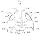
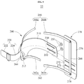
- FIG. 3 is a rear view illustrating a frame module according to at least one example embodiment
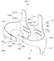
- FIG. 4 is an exploded perspective view illustrating a frame module according to at least one example embodiment.
- a reinforcement belt is omitted in FIG. 4 .
- the frame module 20 may include the first side frame 100L, the second side frame 100R, and a fastening member 150.
- the first side frame 100L and the second side frame 100R may be connected to each other to form a single closed curve.
- the first side frame 100L and the second side frame 100R may be detachable from each other. Therefore, the first side frame 100 and the second side frame 100R may also be referred to as a "first separable frame” and a "second separable frame", respectively.
- wearability for the user may increase.
- the first side frame 100L may cover one side surface of the waist of the user, a portion of a front surface of the waist of the user, and a portion of a rear surface of the waist of the user.
- the first side frame 100L may be provided roughly in a U-shape.
- the first side frame 100L may be provided using a relatively thin board.
- the first side frame 100L may be provided using a flexible material to improve a degree of contact with the user. In this example, the first side frame 100L may be deformed based on a shape of the user to be in close contact with the user.
- the first side frame 100L may include a first central portion 110L, a first front extending portion 120L, and a first rear extending portion 130L.
- the first central portion 110L may include a curved surface corresponding to one side surface of the user, and be disposed on the one side surface of the user.
- the first central portion 110L may include a joint mounting portion 115L configured to extend toward a hip joint portion of the user.
- the joint mounting portion 115L may be provided to cover the hip joint portion.
- the rotating member 42 of FIG. 1 may be provided on the joint mounting portion 115L.
- the first front extending portion 120L may extend from the first central portion 110L to cover at least a portion of the front surface of the user.
- the first front extending portion 120L may be detachable from the second side frame 100R.
- the first front extending portion 120L may include a first binding portion 122L, and a first connecting portion 124L.
- the first binding portion 122L may be detachable from the second side frame 100R.
- the first binding portion 122L may include a base plate having a shape of a board, and a hook and loop fastener provided on the base plate.
- the first binding portion 122L may also be fastened with the second side frame 100R in a structure of a buckle.
- the shape of the first binding portion 122L is not limited thereto.
- the first connecting portion 124L may rotatably connect the first binding portion 122L to the first central portion 110L.
- the first connecting portion 124L may be a ring or a hinge.
- the first rear extending portion 130L may extend from the first central portion 110L to cover at least a portion of the rear surface of the user.
- the first rear extending portion 130L may extend from the first central portion 110L toward an opposite side of the first front extending portion 110L.
- the first rear extending portion 130L may be disposed on the opposite side of the first front extending portion 120L based on the user.
- the first rear extending portion 130L may be detachable from the second side frame 100R.
- the first rear extending portion 130L includes a first guide portion 132L.
- the first guide portion 132L may guide the second side frame 100R to slide with respect to the first rear extending portion 130L.
- the first guide portion 132L may be a slot provided lengthwise in an extending direction of the first rear extending portion 130L.
- the first guide portion 132L may also be referred to as a "guide slot”.
- a plurality of first guide portions 132L may be provided.
- the plurality of first guide portions 132L may be provided in parallel.
- the fastening member 150 may be connected to the first guide portion 132L.
- the first side frame 100L may further include a first supporting member 140L.
- the first supporting member 140L may include a first upper supporting member 142L and a first lower supporting member 144L.
- the first upper supporting member 142L may extend from the first rear extending portion 130L in an upward direction to support an upper side of the user.
- the first upper supporting member 142L may extend in a direction orthogonal to a longitudinal direction of the first rear extending portion 130L.
- the first upper supporting member 142L may support a dorsal portion of the user.
- the first upper supporting member 142L may extend from the first rear extending portion 130L to a portion corresponding to about a midpoint of the dorsal portion of the user.
- the first upper supporting member 142L may include a first extension 141L whose width increases in a direction of the first rear extending portion 130L.
- the first upper supporting member 142L may efficiently prevent a rotation of the first side frame 100L by the torque generated by the driving module 30. For example, referring to FIG. 4 , when the driving module 30 rotates counterclockwise, counterclockwise torque may be applied to the first side frame 100L. In this example, the first upper supporting member 142L having a long moment arm from the driving module 30 may prevent a counterclockwise rotation of the first side frame 100L by reaction force received from the back of the user, while transferring relatively small force to the back of the user.
- the first lower supporting member 144L may extend from the first rear extending portion 130L in a downward direction to support a lower side of the user.
- the first lower supporting member 144L may extend in a direction orthogonal to the longitudinal direction of the first rear extending portion 130L.
- the first lower supporting member 144L may support a hip portion of the user.
- the first lower supporting member 144L may efficiently prevent a rotation of the first side frame 100L by the torque generated by the driving module 30. For example, referring to FIG. 4 , when the driving module 30 rotates clockwise, clockwise torque may be applied to the first side frame 100L. In this example, the first lower supporting member 144L having a long moment arm from the driving module 30 may prevent a clockwise rotation of the first side frame 100L by reaction force received from a hip of the user, while transferring relatively small force to the hip of the user.
- the second side frame 100R may be provided in a shape symmetrical to the first side frame 100L.
- the same names may be used to describe the elements included in the first side frame 100L described above and elements having common functions. Unless otherwise mentioned, the descriptions related to the first side frame 100L may be applicable to the second side frame 100R.
- the second side frame 100R may cover a remaining portion of the waist of the user yet to be covered by the first side frame 100L.
- the second side frame 100R may cover another side of the waist of the user, a remaining portion of the front surface of the waist of the user, and a remaining portion of the rear surface of the waist of the user. At least a portion of the second side frame 100R may overlap the first side frame 100L.
- the second side frame 100R may include a second central portion 110R, a second front extending portion 120R, and a second rear extending portion 130R.
- the second central portion 110R may include a curved surface corresponding to another side surface of the user, and be disposed on the other side surface of the user.
- the second central portion 110R may be disposed to face the first central portion 110L.
- the second central portion 110R may include a joint mounting portion 115R configured to extend toward a hip joint portion of the user.
- the joint mounting portion 115R may be provided to cover the hip joint portion.
- the second front extending portion 120R may extend from the second central portion 110R to cover at least a portion of the front surface of the user.
- the second front extending portion 120R may be detachable from the first binding portion 122L.
- the second front extending portion 120R may include a second binding portion 122R, and a second connecting portion 124R.
- the second binding portion 122R may be detachable from the first binding portion 122L.
- the second binding portion 122R may include a hook and loop fastener corresponding to the first binding portion 122L.
- the second binding portion 122R may include a structure of a buckle corresponding to the first binding portion 122L.
- the second connecting portion 124R may rotatably connect the second binding portion 122R to the second central portion 110R.
- the second rear extending portion 130R may extend from the second central portion 110R to cover at least a portion of the rear surface of the user.
- the second rear extending portion 130R may extend from the second central portion 110R towards an opposite side of the second front extending portion 120R.
- the second rear extending portion 130R may be disposed on the opposite side of the second front extending portion 120R based on the user.
- the second rear extending portion 130R may be detachable from the first rear extending portion 130L.
- the second rear extending portion 130R may include a second guide portion 132R.
- the second guide portion 132R may guide the first rear extending portion 130L to slide with respect to the second rear extending portion 130R.
- the second guide portion 132R may be a slot provided lengthwise in an extending direction of the second rear extending portion 130R.
- the second guide portion 132R may be provided in a shape corresponding to the first guide portion 132L.
- the second guide portion 132R may overlap at least a portion of the first guide portion 132L.
- the fastening member 150 may be connected to the overlapping portion between the second guide portion 132R and the first guide portion 132L.
- the fastening member 150 may fasten the second rear extending portion 130R with the first rear extending portion 130L.
- the second side frame 100R may further include a second supporting member 140R.
- the second supporting member 140R may include a second upper supporting member 142R, and a second lower supporting member 144R.
- the second upper supporting member 142R may be provided in a shape symmetrical to the first upper supporting member 142L.
- the second upper supporting member 142R and the first upper supporting member 142L may be disposed on both sides based on a spine of the user, to support erector spinae muscles of the user.
- the second lower supporting member 144R may be provided in a shape symmetrical to the first lower supporting member 144L.
- the second lower supporting member 144R and the first lower supporting member 144L may be disposed to support hip muscles of the user.
- the fastening member 150 may fasten the first side frame 100L with the second side frame 100R.
- the fastening member 150 may penetrate through the first guide portion 132L and the second guide portion 132R to prevent relative movements of the first rear extending portion 130L and the second rear extending portion 130R.
- the fastening member 150 may include a bolt and a nut configured to pressurize the first rear extending portion 130L and the second rear extending portion 130R simultaneously.
- one of the first guide portion 132L and the second guide portion 132R may be provided in a form of a threaded hole, and the fastening member 150 may be a bolt having threads corresponding to the hole.
- FIG. 5 is a view illustrating an installation structure of a reinforcement belt according to at least one example embodiment.
- both end portions of the reinforcement belt 160 may be fixed to both portions of a side frame 100 to restrict an elongating level of the side frame 100 in a desired (or, alternatively, a predetermined) direction.
- the reinforcement belt 160 may restrict a maximum elongation distance of the side frame 100.
- the reinforcement belt 160 may reinforce a strength of the side frame 100, thereby preventing splaying (or, alternatively, stretching or deformation) of the side frame 100.
- the reinforcement belt 160 may be disposed to be in close contact with the user, and distribute force or torque applied to the side frame 100 by the driving module 30 to the body of the user.
- the reinforcement belt 160 may prevent an impact to the user caused in response to a serious distortion of a portion of the side frame 100 positioned at a relatively long distance from the driving module 30. Further, the reinforcement belt 160 may prevent an excessive distortion of the side frame 100, thereby increasing wearability for the user. In addition, the reinforcement belt 160 may reduce an error or uncertainty caused in response to the distortion of the side frame 100, thereby helping to control assistance force precisely.
- the frame module 20 may include joint belts 162 and 164. One end portion of each of the joint belts 162 and 164 may be connected to one side of a joint mounting portion 115.
- the joint belts 162 and 164 may reduce force or torque transferred to the joint mounting portion 115.
- the joint mounting portion 115 may correspond to a portion in which the force or torque generated by the driving module 30 is transferred directly to the frame module 20.
- the joint mounting portion 115 may reduce bending of a portion of the frame module 20 disposed on a path along which the force or torque is propagated from the joint mounting portion 115 to another portion of the frame module 20.
- the frame module 20 may include an upper supporting belt 166 of which one end portion is connected to an upper supporting member 142, and a lower supporting belt 168 of which one end portion is connected to a lower supporting member 144.
- another end portion of the upper supporting belt 166 may be connected to a front portion of the side frame 100, and another end portion of the lower supporting belt 168 may be connected to the joint mounting portion 115.
- the upper supporting belt 166 and the lower supporting belt 168 may be collectively referred to as supporting belts 166 and 168.
- the upper supporting member 142 or the lower supporting member 144 may have a relatively long moment arm from the driving module 30, compared to other portions of the frame module 20.
- the supporting belts 166 and 168 may reduce splaying (or, alternatively, stretching or deformation) of the frame module 20 while transferring relatively small force to the body of the user.
- the joint belt 164, the upper supporting belt 166, and the lower support belt 168 of the frame module 20 may be considered crossing belts 164, 166, and 168 connected in a direction intersecting a circumferential direction of the waist of the user.
- the crossing belts 164, 166, and 168 may prevent splaying (or, alternatively, stretching or deformation) of the frame module 20 due to torque generated by the driving module 30 in a direction of the torque. Further, the crossing belts 164, 166, and 168 may prevent bobbing of the frame module 20, in detail, an occurrence of a pitch rotation motion, rather than being in close contact with the user.
- the joint belt 162 of the frame module 20 may be considered a parallel belt 162 that is parallel to a circumferential direction of the waist of the user.
- the parallel belt 162 may prevent splaying (or, alternatively, stretching or deformation) of the frame module 20 in the circumferential direction of the waist, thereby preventing a reduction in a degree of contact in response to the distortion of the frame module 20.
- both end portions of the parallel belt 162 may be connected to one side of the joint mounting portion 115 and one side of the lower supporting member 144.
- the joint belt 164 of the frame module 20 may be considered a bone belt 164 disposed in a longitudinal direction of a bone of the user.
- the bone belt 164 may be disposed along an iliac crest of a human.
- the bone belt 164 may also be referred to as an iliac crest belt.
- the iliac crest is a bone protruding around a pelvis outward relatively much.
- a skin layer around the iliac crest is relatively thin, compared to other portions, and thus, the iliac crest may be a suitable supporter.
- One side of the iliac crest belt may be connected to one side of the joint mounting portion 115, and another side of the iliac crest belt may be connected to a front portion of the side frame 100, for example, a central portion 110 or a front extending portion 120.
- the lower support belt 168 of the frame module 20 may be considered a connecting belt 168 configured to connect an end portion of the upper supporting member 142 to an end portion of the lower supporting member 144.
- the upper supporting member 142 and lower supporting member 144 may have long moment arms from the driving module 30 in upward and downward directions, respectively. Accordingly, the upper supporting member 142 and lower supporting member 144 may reduce an effect of the driving module 30 using relatively small force.
- the connecting belt 168 may reinforce the stiffness of end portions of the upper supporting member 142 and the lower supporting member 144, thereby increasing the aforementioned functions of the upper supporting member 142 and the lower supporting member 144.
- the upper support belt 166 of the frame module 20 may be considered a side belt 166 of which one side is connected to the upper supporting member 142 or the lower supporting member 144 and another side is connected to a front portion of the side frame 100, for example, the central portion 110 or the front extending portion 120.
- the connecting belt 168 may not prevent a distortion occurring when the upper supporting member 142 and the lower supporting member 144 rotate in the same direction, the side belt 166 may prevent such a distortion.
- one side of the side belt 166 may be connected to the upper supporting member 142, and another side of the side belt 166 may extend to the central portion 110.
- At least two of the plurality of belts 162, 164, 166, and 168 may be connected to each other.
- the at least two belts may be rotatably connected to a single hinge provided in the frame module 20.
- the frame module 20 may include a plurality of belts 162, 164, 166, and 168 that form a single closed loop.
- the aforementioned joint belts, supporting belts, crossing belts, parallel belt, bone belt, connecting belt, and side belt may be collectively referred to as the reinforcement belt 160.
- a single reinforcement belt 160 may perform functions of at least two of the seven types of reinforcement belts as described above.
- one or more of the seven types of reinforcement belts described above may be omitted.
- one or more of belts 162, 164, 166 and 168 may be omitted.
- FIG. 6 is a view illustrating a reinforcement belt according to at least one example embodiment.
- a length of the reinforcement belt 160 may be adjustable.
- a user may adjust the length of the reinforcement belt 160 so that the reinforcement belt 160 may be in close contact with a body of the user.
- the reinforcement belt 160 may include a first sub-belt 160a and a second sub-belt 160b that may be separate from or fastened to each other.
- the first sub-belt 160a may include a sub-belt body 160aa, a frame connecting portion 160ab connected to the side frame 100, and a sub-belt connecting portion 160ac connected to the second sub-belt 160b.
- the frame connecting portion 160ab may be rotatably connected to, for example, the side frame 100.
- the frame connecting portion 160ab may have a structure of a hinge.
- the sub-belt connecting portion 160ac may be detachable from, for example, the second sub-belt 160b.
- the sub-belt connecting portion 160ac may have a structure of a hook and loop fastener.
- the second sub-belt 160b may include, similar to the first sub-belt 160a, a sub-belt body 160ba, a frame connecting portion 160bb, and a sub-belt connecting portion 160bc.
- the length of the reinforcement belt 160 may be adjusted to be suitable for a body shape of the user.
- FIG. 7 is a view illustrating a modified example of a reinforcement belt according to at least one example embodiment.
- a reinforcement belt 260 may include a first sub-belt 260a and a second sub-belt 260b that, in some example embodiments, may be detachable from each other in a manner of a snap fastener.
- the sub-belt connecting portion 160ac may include a snap fastener.
- a length of the reinforcement belt 260 may be adjusted in a manner of a buckle.
- the sub-belt connecting portion 160ac may include a buckle.
- the manner to adjust the length of the reinforcement belt 260 is not limited by the structures illustrated in FIGS. 6 and 7 .
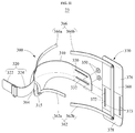
- FIG. 8 is an exploded perspective view of a frame module according to at least one example embodiment
- FIG. 9 is a view illustrating an installation structure of a reinforcement belt according to at least one example embodiment.
- a frame module 22 may include a first side frame 200L, a second side frame 200R, a fastening member 250, and a supporting member 270.
- the supporting member 270 may include a fixing portion 272, an upper supporting member 276, and a lower supporting member 278.
- the fixing portion 272 may overlap the first side frame 200L and the second side frame 200R.
- a first rear extending portion 230L may be fixed to one side of the fixing portion 272, and a second rear extending portion 230R may be fixed to another side of the fixing portion 272.
- a third guide portion 273 may be provided in the fixing portion 272.
- the third guide portion 273 may be provided in a shape corresponding to a first guide portion 232L and a second guide portion 232R.
- the upper supporting member 276 may extend from the fixing portion 272 in an upward direction to support an upper side of the user.
- the upper supporting member 276 may extend in a direction orthogonal to a longitudinal direction of the fixing portion 272.
- the upper supporting member 276 may support a dorsal portion of the user.
- the upper supporting member 276 may extend from the fixing portion 272 to a portion corresponding to a midpoint of the dorsal portion of the user.
- the lower supporting member 278 may extend from the fixing portion 272 in a downward direction to support a lower side of the user.
- the lower supporting member 278 may extend in a direction orthogonal to the longitudinal direction of the fixing portion 272.
- the lower supporting member 278 may support a hip portion of the user.
- the fastening member 250 may include a first fastening member 250L configured to fasten the first rear extending portion 230L with the fixing portion 272, and a second fastening member 250R configured to fasten the second rear extending portion 230R with the fixing portion 272.
- a single fastening member may be used to fasten the first rear extending portion 230L and the second rear extending portion 230R with the fixing portion 272.
- the frame module 22 may include at least one of joint belts 262 and 264, supporting belts 262 and 268, crossing belts 264, 266, and 268, a parallel belt 262, a bone belt 264, a connecting belt 268, and a side belt 266.
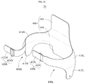
- FIG. 10 is an exploded perspective view of a frame module according to at least one example embodiment
- FIG. 11 is a view illustrating an installation structure of a reinforcement belt according to at least one example embodiment.
- a frame module 23 may include a first side frame 300L, a second side frame 300R, a fastening member 350, and a supporting member 370.
- the supporting member 370 may include a fixing portion 372, an upper supporting member 376, and a lower supporting member 378.
- the fixing portion 372 may overlap the first side frame 300L and the second side frame 300R.
- a first rear extending portion 330L may be fixed to one side of the fixing portion 372, and a second rear extending portion 330R may be fixed to another side of the fixing portion 372.
- a third guide portion 373 may be provided in the fixing portion 372.
- the third guide portion 373 may include a slot provided in a direction perpendicular to a first guide portion 332L of the first side frame 300L.
- the third guide portion 373 may further include a slot provided in a direction perpendicular to a second guide portion 332R of the second side frame 300R.
- the fastening member 350 may include a first fastening member 350L configured to fasten the first rear extending portion 330L with the fixing portion 372, and a second fastening member 350R configured to fasten the second rear extending portion 330R with the fixing portion 372.
- a single fastening member may be used to fasten the first rear extending portion 330L and the second rear extending portion 330R with the fixing portion 372.
- the frame module 23 may include at least one of joint belts 362 and 364, supporting belts 362 and 368, crossing belts 364, 366, and 368, a parallel belt 362, a bone belt 364, a connecting belt 368, and a side belt 366.
- the belts 362, 364, 366 and 368 may prevent an impact to the user caused in response to a distortion of a portion of the side frame 23 positioned at a relatively long distance from the driving module 30.
- the belts 362, 364, 366 and 368 may reduce an error or uncertainty caused in response to the distortion of the side frame 23, thereby helping to control assistance force precisely
- FIG. 12 is an exploded perspective view of a frame module according to at least one example embodiment
- FIG. 13 is a view illustrating an installation structure of a reinforcement belt according to at least one example embodiment.
- a frame module 24 may include a first side frame 400L, a second side frame 400R, and a supporting member 440.
- the supporting member 440 may include an upper supporting member 442, and a lower supporting member 444.
- the first side frame 400L, the second side frame 400R, and the supporting member 440 may be provided as an integral body.
- the frame module 24 may include at least one of joint belts 462 and 464, supporting belts 462 and 468, crossing belts 464, 466, and 468, a parallel belt 462, a bone belt 464, a connecting belt 468, and a side belt 466.
- the belts 462, 464, 466 and 468 may prevent an impact to the user caused in response to a distortion of a portion of the side frame 24 positioned at a relatively long distance from the driving module 30.
- the belts 462, 464, 466 and 468 may reduce an error or uncertainty caused in response to the distortion of the side frame 24, thereby helping to control assistance force precisely
Abstract
Description
- At least one example embodiment relates to a frame module and/or a motion assistance apparatus including the same.
- With the onset of rapidly aging societies, there may be an increase in the number of people experiencing inconvenience and/or pain from joint problems. Thus, there is a growing interest in motion assistance apparatuses enabling the elderly and/or patients having joint problems to walk with less effort. Furthermore, motion assistance apparatuses increasing muscular strength of human bodies are desired for military purposes.
- In general, motion assistance apparatuses for assisting motion of lower parts of bodies may include body frames disposed on trunks of users, pelvic frames coupled to lower sides of the body frames to cover pelvises of the users, femoral frames disposed on thighs of the users, sural frames disposed on calves of the users, and/or pedial frames disposed on feet of the users. The pelvic frames and femoral frames may be connected rotatably by hip joint portions, the femoral frames and sural frames may be connected rotatably by knee joint portions, and/or the sural frames and pedial frames may be connected rotatably by ankle joint portions.
- Some example embodiments relate to a frame module.
- In some example embodiment, the frame module may include a frame configured to enclose a portion of a user, and at least one reinforcement belt of which both end portions are connected to both sides of the frame, thereby restricting a splaying level and/or reinforcing the stiffness of the frame in a predetermined direction. The splaying level of the frame may include here the level of stretching or deformation of the frame. For instance, the at least one reinforcement belt may enhance the stiffness and softly enclose a body of a user at the same time, thereby increasing wearability Through this, the wearability of the frame module may increase for the user and the stiffness of the flexible waist frame may be enhanced without increasing the weight.
- A length of the reinforcement belt may be adjustable.
- The reinforcement belt may include a first sub-belt of which one end portion is connected to one side of the frame, and a second sub-belt of which one end portion is connected to another side of the frame. Another end portion of the first sub-belt may be detachable from another end portion of the second sub-belt.
- One end portion of at least one of the first sub-belt and the second sub-belt may be rotatably connected to the frame.
- The both end portions of the reinforcement belt may be connected to inner surfaces of the frame to support the user in a state in which the user is spaced apart from the frame.
- At least one of the both end portions of the reinforcement belt may be rotatably connected to the frame.
- A plurality of reinforcement belts may be provided, and the plurality of reinforcement belts may be connected to a single hinge axis provided in the frame.
- A plurality of reinforcement belts may be provided, and the plurality of reinforcement belts may be connected to each other to form a single closed loop.
- The frame may include a joint mounting portion in which a rotating member configured to be rotated by a driving module is to be installed, and the reinforcement belt may correspond to a joint belt of which one end portion is connected to one side of the joint mounting portion.
- The frame may include a supporting member configured to extend in a direction perpendicular to a circumferential direction of the portion of the user to support a body of the user, and the reinforcement belt may correspond to a supporting belt of which one end portion is connected to an end portion of the supporting member.
- The frame may include an upper supporting member and a lower supporting member configured to extend upward and downward in a direction perpendicular to a circumferential direction of the portion of the user, and the frame module may further include an upper supporting belt of which one end portion is connected to the upper supporting member, and a lower supporting belt of which one end portion is connected to the lower supporting member.
- The reinforcement belt may correspond to a crossing belt connected to the frame in a direction intersecting a circumferential direction of the portion of the user.
- The reinforcement belt may correspond to a parallel belt connected to the frame in a direction parallel to a circumferential direction of the portion of the user.
- The frame may include a joint mounting portion in which a rotating member configured to be rotated by a driving module is to be disposed, and a supporting member configured to extend in a direction perpendicular to a circumferential direction of the portion of the user to support a body of the user, and both end portions of the parallel belt may be connected to one side of the joint mounting portion and one side of the supporting member.
- The reinforcement belt may correspond to a bone belt disposed in a longitudinal direction of a bone of the user.
- The bone belt may correspond to an iliac crest belt disposed along an iliac crest of the user.
- The frame may include a joint mounting portion in which a rotating member configured to be rotated by a driving module is to be disposed. One side of the iliac crest belt may be connected to one side of the joint mounting portion, and another side of the iliac crest belt may be connected to a front portion of the frame.
- The frame may include an upper supporting member and a lower supporting member configured to extend upward and downward in a direction perpendicular to a circumferential direction of the portion of the user, and the reinforcement belt may correspond to a connecting belt configured to connect an end portion of the upper supporting member to an end portion of the lower supporting member.
- The frame may include a supporting member configured to extend in a direction perpendicular to a circumferential direction of the portion of the user to support a body of the user, and the reinforcement belt may correspond to a side belt of which one side is connected to the supporting member and another side is connected to a front portion of the frame.
- In an embodiment the frame module is a flexible waist wearing portion, for example a flexible waist wearing portion in a walking assist device.
- Other example embodiments relate to a motion assistance apparatus, for example a walking assist device.
- In some example embodiments, the motion assistance apparatus may include a driving module configured to generate power to assist a motion of a user, a rotating member configured to be rotated by the driving module to assist a rotary motion of a joint portion of the user, and a frame module including a frame configured to enclose a portion of the user, the frame including a joint mounting portion in which the rotating member is to be disposed, and at least one reinforcement belt connected to both sides of the frame to reinforce a stiffness of the frame.
- The frame may further include a supporting member configured to extend in a direction perpendicular to a circumferential direction of the portion of the user to support a body of the user, and the reinforcement belt may include a joint belt of which one end portion is connected to one side of the joint mounting portion, and a supporting belt of which one end portion is connected to an end portion of the supporting member.
- Some example embodiments relate to a frame module.
- In some example embodiments, the frame module includes a plurality of interlocking frames configured to enclose a portion of a user; and at least one reinforcement belt configured to restrict a deformation of the plurality of interlocking frames in response to a torque applied thereto.
- In some example embodiments, the plurality of interlocking frames are flexible frames and are separated by an adjustable distance to secure the frame module onto the portion of the user, the plurality of interlocking frames configured to have joint assemblies mounted thereon, the joint assemblies configured to apply a torque to a support attached to at least a thigh of the user to assist the user with movement of their hip joints.
- In some example embodiments, the plurality of interlocking frames includes a first interlocking frame and a second interlocking frame, and the at least one reinforcement belt includes a first sub-belt and a second sub-belt connected to the first interlocking frame and the second interlocking frame, respectively, the first sub-belt configured to detach from the second sub-belt to allow the user to remove the frame module.
- In some example embodiments, the at least one reinforcement belt includes a plurality of reinforcement belts connected together in a closed loop.
- In some example embodiments, the ends of each of the plurality of reinforcement belts are connected to inner surfaces of the plurality of interlocking frames such that the at least one reinforcement belt is configured to maintain a gap between the plurality of interlocking frames and the user when the torque is applied to the plurality of interlocking frames.
- In some example embodiments the reinforcement belt is made of a soft, light-weighted fabric material, for instance webbing belt or seat belt, so as to increase the comfort for the user. Furthermore, the soft, light-weighted fabric material of the reinforcement belt may include an essentially non-stretchable fabric so as to enable the reinforcement belt to provide the desired stiffness in the predetermined direction.
- In embodiments the frame is a flexible frame. This may increase the wearability of the frame. The required stiffness of this flexible frame in one or more directions may be provided by an appropriate arrangement of the one of or more reinforcement belts.
- Additional aspects of example embodiments will be set forth in part in the description which follows and, in part, will be apparent from the description, or may be learned by practice of the disclosure.
- These and/or other aspects will become apparent and more readily appreciated from the following description of example embodiments, taken in conjunction with the accompanying drawings of which:
-
FIG. 1 is a front view of a motion assistance apparatus according to at least one example embodiment; -
FIG. 2 is a side view of a motion assistance apparatus according to at least one example embodiment; -
FIG. 3 is a rear view of a frame module according to at least one example embodiment; -
FIG. 4 is an exploded perspective view of a frame module according to at least one example embodiment; -
FIG. 5 is a view illustrating an installation structure of a reinforcement belt according to at least one example embodiment; -
FIG. 6 is a view illustrating a reinforcement belt according to at least one example embodiment; -
FIG. 7 is a view illustrating a modified example of a reinforcement belt according to at least one example embodiment; -
FIG. 8 is an exploded perspective view of a frame module according to at least one example embodiment; -
FIG. 9 is a view illustrating an installation structure of a reinforcement belt according to at least one example embodiment; -
FIG. 10 is an exploded perspective view of a frame module according to at least one example embodiment; -
FIG. 11 is a view illustrating an installation structure of a reinforcement belt according to at least one example embodiment; -
FIG. 12 is an exploded perspective view of a frame module according to at least one example embodiment; and -
FIG. 13 is a view illustrating an installation structure of a reinforcement belt according to at least one example embodiment. - Hereinafter, some example embodiments will be described in detail with reference to the accompanying drawings. Regarding the reference numerals assigned to the elements in the drawings, it should be noted that the same elements will be designated by the same reference numerals, wherever possible, even though they are shown in different drawings. Also, in the description of example embodiments, detailed description of well-known related structures or functions will be omitted when it is deemed that such description will cause ambiguous interpretation of the present disclosure.
- It should be understood, however, that there is no intent to limit this disclosure to the particular example embodiments disclosed. On the contrary, example embodiments are to cover all modifications, equivalents, and alternatives falling within the scope of the example embodiments. Like numbers refer to like elements throughout the description of the figures.
- In addition, terms such as first, second, A, B, (a), (b), and the like may be used herein to describe components. Each of these terminologies is not used to define an essence, order or sequence of a corresponding component but used merely to distinguish the corresponding component from other component(s). It should be noted that if it is described in the specification that one component is "connected", "coupled", or "joined" to another component, a third component may be "connected", "coupled", and "joined" between the first and second components, although the first component may be directly connected, coupled or joined to the second component.
- The terminology used herein is for the purpose of describing particular embodiments only and is not intended to be limiting. As used herein, the singular forms "a," "an," and "the," are intended to include the plural forms as well, unless the context clearly indicates otherwise. It will be further understood that the terms "comprises," "comprising," "includes," and/or "including," when used herein, specify the presence of stated features, integers, steps, operations, elements, and/or components, but do not preclude the presence or addition of one or more other features, integers, steps, operations, elements, components, and/or groups thereof.
- It should also be noted that in some alternative implementations, the functions/acts noted may occur out of the order noted in the figures. For example, two figures shown in succession may in fact be executed substantially concurrently or may sometimes be executed in the reverse order, depending upon the functionality/acts involved.
- Various example embodiments will now be described more fully with reference to the accompanying drawings in which some example embodiments are shown. In the drawings, the thicknesses of layers and regions are exaggerated for clarity.
-
FIG. 1 is a front view of a motion assistance apparatus according to at least one example embodiment, andFIG. 2 is a side view of a motion assistance apparatus according to at least one example embodiment. - Referring to
FIGS. 1 and2 , amotion assistance apparatus 10 may be worn by a user to assist a motion of the user. - The user may correspond to a human, an animal, or a robot. However, the user is not limited thereto. In addition, although
FIG. 1 illustrates a case in which themotion assistance apparatus 10 assists the thighs of the user, themotion assistance apparatus 10 may also assist a motion of an upper body, for example, a hand, an upper arm, and a lower arm of the user. Further, themotion assistance apparatus 10 may assist a motion of another part of a lower body, for example, a foot, and a calf of the user. Themotion assistance apparatus 10 may assist a motion of a part of the user. - Hereinafter, a case in which the
motion assistance apparatus 10 assists motions of thighs of a human will be described. However, example embodiments are not limited thereto. - The
motion assistance apparatus 10 may include aframe module 20, a drivingmodule 30, ajoint assembly 40, and a supportingmodule 50. - The
frame module 20 may be fixed to the user. Theframe module 20 may be provided in a form of covering an outer surface of the user. For example, theframe module 20 may be fixed to a side of a waist of the user, and include a curved surface corresponding to a contact portion of the user. Theframe module 20 includes afirst side frame 100L disposed on one side of the waist of the user, asecond side frame 100R disposed on another side of the waist of the user, and areinforcement belt 160. Thefirst side frame 100L and thesecond side frame 100R may be detachable from each other, or provided as an integral body. Thefirst side frame 100L and thesecond side frame 100R may be referred to as interlocking frames. - The
frame module 20 may have flexibility to be in close contact with a body of the user. For example, theframe module 20 may be formed using a flexible material for instance plastic, or may be formed using a rigid material in a sufficiently thin thickness. In this example, theframe module 20 may also be referred to as a flexible frame module. - When the
frame module 20 has flexibility as described above, theframe module 20 may be bent by a force or torque generated by the drivingmodule 30. In particular, to assist a walking motion of the user,respective driving modules 30 disposed on both sides of theframe module 20 may rotate in opposite directions. In this example, torques in different directions may be alternately applied to the both sides of theframe module 20, whereby theframe module 20 may be distorted in response to the motions of the drivingmodules 30. Accordingly, theframe module 20 may further include at least onereinforcement belt frame module 20. The at least onereinforcement belt reinforcement belt 160. - The
reinforcement belt 160 may be provided in at least one of thefirst side frame 100L and thesecond side frame 100R. In some example embodiments, thereinforcement belt 160 may correspond to a fabric material with little elasticity such that thereinforcement belt 160 may be relatively thin as compared to a thick, heavy reinforcing member. Thus, a sufficient stiffness may be secured without increasing the total weight of theframe module 20. Each side of thereinforcement belt 160 may be fixed to a portion of the at least one side frame, thereby reinforcing the stiffness of theframe module 20 in a required direction. Thereinforcement belt 160 may prevent splaying of theframe module 20 in an undesired direction. - The
reinforcement belt 160 may be provided in an inner surface of the at least oneside frame reinforcement belt 160 to be sufficiently short, thereinforcement belt 160 may support the user in a state in which the user is spaced apart from the inner surface of the at least oneside frame reinforcement belt 160 may prevent a direct contact between the body of the user and the at least oneside frame - At least one of the end portions of the
reinforcement belt 160 may be rotatably connected to the at least oneside frame reinforcement belt 160 and the at least one side frame may be changeable. In this example, thereinforcement belt 160 may rotate to be suitable for a shape of the body of the user, thereby increasing wearability for the user. - The driving
module 30 may provide power to be transmitted to thejoint assembly 40. For example, the drivingmodule 30 may be disposed in a lateral direction of thejoint assembly 40 such that an axis of rotation of thediving module 30 may be spaced apart from an axis of rotation of thejoint assembly 40. Therefore, when compared to a case in which thedriving module 30 and thejoint assembly 40 share an axis of rotation, a protruding height from the user may relatively decrease. In other example embodiments, the drivingmodule 30 may be more spaced apart from thejoint assembly 40. Therefore, a power transmitting module may be additionally provided to transmit power from the drivingmodule 30 to thejoint assembly 40. The power transmitting module may be a rotary body such as, for example, a gear, or a longitudinal member such as, for example, a wire, a cable, a string, a rubber band, a spring, a belt, and a chain. - The
joint assembly 40 may receive power from the drivingmodule 30, and assist a motion of a joint portion of the user. Thejoint assembly 40 may be disposed on one or more of the sides of theframe module 20 at a position corresponding to the joint portion of the user. One end of thejoint assembly 40 may be connected to thedriving module 30, and another end of thejoint assembly 40 may be connected to the supportingmodule 50. - The
joint assembly 40 may include a rotatingmember 42, and a connectingmember 44. The rotatingmember 42 may rotate using power received from the drivingmodule 30. For example, the rotatingmember 42 may be disposed on one or more of the sides of the hip joints of the user. The connectingmember 44 may connect the rotatingmember 42 to the supportingmodule 50, and rotate using torque of the rotatingmember 42. The connectingmember 44 may be provided, for example, in a hinge connection structure. By a hinge axis of the hinge connection structure and an axis of rotation of the rotatingmember 42, the supportingmodule 50 may perform a two degree of freedom (DOF) motion with respect to theframe module 20. - The supporting
module 50 may support a portion of the user, and assist a motion of the portion of the user. The supportingmodule 50 may be configured to rotate using torque of thejoint assembly 40. The supportingmodule 50 may include a supportingframe 52, an applyingmember 54, and a supportingband 56. - The supporting
frame 52 may transmit force to a portion of the user. One end portion of the supportingframe 52 may be rotatably connected to thejoint assembly 40, and another end portion of the supportingframe 52 may be connected to the supportingband 56 to transmit force to a portion of the user. For example, the supportingframe 52 may push or pull a thigh of the user. The supportingframe 52 may extend and be bent in a longitudinal direction of the thigh of the user to cover at least a portion of the circumference of the thigh of the user. The one end portion of the supportingframe 52 may be disposed on a side surface of the thigh of the user, and the other portion of the supportingframe 52 may be disposed on a front surface of the thigh of the user. A surface on the side of the one end portion of the supportingframe 52 may be orthogonal to a surface on the side of the other end portion of the supportingframe 52. - The supporting
frame 52 may be movably connected to the connectingmember 44. By relative motions of the supportingframe 52 and the connectingmember 44, a total length from thejoint assembly 40 to the supportingband 56 may be variable. In this example, the supportingmodule 50 may perform a three DOF motion with respect to theframe module 20. - The applying
member 54 may be connected to the other end portion of the supportingframe 52 to apply force to a portion of the user. For example, the applyingmember 54 may be disposed along the front surface of the thigh of the user, or in a circumferential direction of the thigh of the user to push or pull the thigh of the user. The applyingmember 54 may include a curved surface corresponding to the thigh of the user, and configured to extend from the other end portion of the supportingframe 52 toward both sides of the supportingframe 52. - The supporting
band 56 may be connected to one side of the applyingmember 54. For example, the supportingband 56 may be disposed to cover a circumference of at least a portion of the thigh of the user, thereby preventing separation between the thigh of the user and the supportingframe 52. - Meanwhile, the driving module and/or the supporting module may be additionally provided. For example, the supporting
module 50 may extend to a knee, and an additional joint assembly may be provided in the supportingmodule 50 at a position corresponding to a knee joint. Further, an additional supporting module may be connected to the additional joint assembly. The additional supporting module may support a calf of the user, thereby assisting a motion of the calf. Here, an actuator configured to drive the additional joint assembly may be disposed on one side of the additional joint assembly, or may be disposed in, for example, theframe module 20, to be spaced apart from the additional joint assembly. -
FIG. 3 is a rear view illustrating a frame module according to at least one example embodiment, andFIG. 4 is an exploded perspective view illustrating a frame module according to at least one example embodiment. For ease of description, a reinforcement belt is omitted inFIG. 4 . - Referring to
FIGS. 3 and4 , theframe module 20 may include thefirst side frame 100L, thesecond side frame 100R, and afastening member 150. Thefirst side frame 100L and thesecond side frame 100R may be connected to each other to form a single closed curve. Thefirst side frame 100L and thesecond side frame 100R may be detachable from each other. Therefore, thefirst side frame 100 and thesecond side frame 100R may also be referred to as a "first separable frame" and a "second separable frame", respectively. In the structure as illustrated inFIGS. 3 and4 , by adjusting a fastening distance of thefirst side frame 100L and thesecond side frame 100R based on a body shape of the user, wearability for the user may increase. - The
first side frame 100L may cover one side surface of the waist of the user, a portion of a front surface of the waist of the user, and a portion of a rear surface of the waist of the user. Thefirst side frame 100L may be provided roughly in a U-shape. Thefirst side frame 100L may be provided using a relatively thin board. Thefirst side frame 100L may be provided using a flexible material to improve a degree of contact with the user. In this example, thefirst side frame 100L may be deformed based on a shape of the user to be in close contact with the user. Thefirst side frame 100L may include a firstcentral portion 110L, a firstfront extending portion 120L, and a firstrear extending portion 130L. - The first
central portion 110L may include a curved surface corresponding to one side surface of the user, and be disposed on the one side surface of the user. The firstcentral portion 110L may include ajoint mounting portion 115L configured to extend toward a hip joint portion of the user. Thejoint mounting portion 115L may be provided to cover the hip joint portion. The rotatingmember 42 ofFIG. 1 may be provided on the joint mountingportion 115L. - The first
front extending portion 120L may extend from the firstcentral portion 110L to cover at least a portion of the front surface of the user. The firstfront extending portion 120L may be detachable from thesecond side frame 100R. For example, the firstfront extending portion 120L may include a firstbinding portion 122L, and a first connectingportion 124L. - The first
binding portion 122L may be detachable from thesecond side frame 100R. For example, the firstbinding portion 122L may include a base plate having a shape of a board, and a hook and loop fastener provided on the base plate. In other example embodiments, the firstbinding portion 122L may also be fastened with thesecond side frame 100R in a structure of a buckle. However, the shape of the firstbinding portion 122L is not limited thereto. - The first connecting
portion 124L may rotatably connect the firstbinding portion 122L to the firstcentral portion 110L. For example, the first connectingportion 124L may be a ring or a hinge. - The first
rear extending portion 130L may extend from the firstcentral portion 110L to cover at least a portion of the rear surface of the user. The firstrear extending portion 130L may extend from the firstcentral portion 110L toward an opposite side of the firstfront extending portion 110L. The firstrear extending portion 130L may be disposed on the opposite side of the firstfront extending portion 120L based on the user. The firstrear extending portion 130L may be detachable from thesecond side frame 100R. - The first
rear extending portion 130L includes afirst guide portion 132L. Thefirst guide portion 132L may guide thesecond side frame 100R to slide with respect to the firstrear extending portion 130L. Thefirst guide portion 132L may be a slot provided lengthwise in an extending direction of the firstrear extending portion 130L. In this example, thefirst guide portion 132L may also be referred to as a "guide slot". A plurality offirst guide portions 132L may be provided. The plurality offirst guide portions 132L may be provided in parallel. Thefastening member 150 may be connected to thefirst guide portion 132L. - The
first side frame 100L may further include a first supportingmember 140L. The first supportingmember 140L may include a firstupper supporting member 142L and a first lower supportingmember 144L. - The first
upper supporting member 142L may extend from the firstrear extending portion 130L in an upward direction to support an upper side of the user. The firstupper supporting member 142L may extend in a direction orthogonal to a longitudinal direction of the firstrear extending portion 130L. For example, the firstupper supporting member 142L may support a dorsal portion of the user. The firstupper supporting member 142L may extend from the firstrear extending portion 130L to a portion corresponding to about a midpoint of the dorsal portion of the user. The firstupper supporting member 142L may include afirst extension 141L whose width increases in a direction of the firstrear extending portion 130L. - The first
upper supporting member 142L may efficiently prevent a rotation of thefirst side frame 100L by the torque generated by the drivingmodule 30. For example, referring toFIG. 4 , when the drivingmodule 30 rotates counterclockwise, counterclockwise torque may be applied to thefirst side frame 100L. In this example, the firstupper supporting member 142L having a long moment arm from the drivingmodule 30 may prevent a counterclockwise rotation of thefirst side frame 100L by reaction force received from the back of the user, while transferring relatively small force to the back of the user. - The first lower supporting
member 144L may extend from the firstrear extending portion 130L in a downward direction to support a lower side of the user. The first lower supportingmember 144L may extend in a direction orthogonal to the longitudinal direction of the firstrear extending portion 130L. For example, the first lower supportingmember 144L may support a hip portion of the user. - The first lower supporting
member 144L may efficiently prevent a rotation of thefirst side frame 100L by the torque generated by the drivingmodule 30. For example, referring toFIG. 4 , when the drivingmodule 30 rotates clockwise, clockwise torque may be applied to thefirst side frame 100L. In this example, the first lower supportingmember 144L having a long moment arm from the drivingmodule 30 may prevent a clockwise rotation of thefirst side frame 100L by reaction force received from a hip of the user, while transferring relatively small force to the hip of the user. - The
second side frame 100R may be provided in a shape symmetrical to thefirst side frame 100L. Hereinafter, the same names may be used to describe the elements included in thefirst side frame 100L described above and elements having common functions. Unless otherwise mentioned, the descriptions related to thefirst side frame 100L may be applicable to thesecond side frame 100R. - The
second side frame 100R may cover a remaining portion of the waist of the user yet to be covered by thefirst side frame 100L. Thesecond side frame 100R may cover another side of the waist of the user, a remaining portion of the front surface of the waist of the user, and a remaining portion of the rear surface of the waist of the user. At least a portion of thesecond side frame 100R may overlap thefirst side frame 100L. Thesecond side frame 100R may include a secondcentral portion 110R, a secondfront extending portion 120R, and a secondrear extending portion 130R. - The second
central portion 110R may include a curved surface corresponding to another side surface of the user, and be disposed on the other side surface of the user. The secondcentral portion 110R may be disposed to face the firstcentral portion 110L. The secondcentral portion 110R may include ajoint mounting portion 115R configured to extend toward a hip joint portion of the user. Thejoint mounting portion 115R may be provided to cover the hip joint portion. - The second
front extending portion 120R may extend from the secondcentral portion 110R to cover at least a portion of the front surface of the user. The secondfront extending portion 120R may be detachable from the firstbinding portion 122L. For example, the secondfront extending portion 120R may include a secondbinding portion 122R, and a second connectingportion 124R. - The second
binding portion 122R may be detachable from the firstbinding portion 122L. For example, the secondbinding portion 122R may include a hook and loop fastener corresponding to the firstbinding portion 122L. In other example embodiments, the secondbinding portion 122R may include a structure of a buckle corresponding to the firstbinding portion 122L. - The second connecting
portion 124R may rotatably connect the secondbinding portion 122R to the secondcentral portion 110R. - The second
rear extending portion 130R may extend from the secondcentral portion 110R to cover at least a portion of the rear surface of the user. The secondrear extending portion 130R may extend from the secondcentral portion 110R towards an opposite side of the secondfront extending portion 120R. The secondrear extending portion 130R may be disposed on the opposite side of the secondfront extending portion 120R based on the user. The secondrear extending portion 130R may be detachable from the firstrear extending portion 130L. - The second
rear extending portion 130R may include asecond guide portion 132R. Thesecond guide portion 132R may guide the firstrear extending portion 130L to slide with respect to the secondrear extending portion 130R. Thesecond guide portion 132R may be a slot provided lengthwise in an extending direction of the secondrear extending portion 130R. Thesecond guide portion 132R may be provided in a shape corresponding to thefirst guide portion 132L. When the secondrear extending portion 130R overlaps the firstrear extending portion 130L, thesecond guide portion 132R may overlap at least a portion of thefirst guide portion 132L. Thefastening member 150 may be connected to the overlapping portion between thesecond guide portion 132R and thefirst guide portion 132L. Thefastening member 150 may fasten the secondrear extending portion 130R with the firstrear extending portion 130L. - The
second side frame 100R may further include a second supportingmember 140R. The second supportingmember 140R may include a secondupper supporting member 142R, and a second lower supportingmember 144R. - The second
upper supporting member 142R may be provided in a shape symmetrical to the firstupper supporting member 142L. The secondupper supporting member 142R and the firstupper supporting member 142L may be disposed on both sides based on a spine of the user, to support erector spinae muscles of the user. - The second lower supporting
member 144R may be provided in a shape symmetrical to the first lower supportingmember 144L. The second lower supportingmember 144R and the first lower supportingmember 144L may be disposed to support hip muscles of the user. - The
fastening member 150 may fasten thefirst side frame 100L with thesecond side frame 100R. Thefastening member 150 may penetrate through thefirst guide portion 132L and thesecond guide portion 132R to prevent relative movements of the firstrear extending portion 130L and the secondrear extending portion 130R. In an example, thefastening member 150 may include a bolt and a nut configured to pressurize the firstrear extending portion 130L and the secondrear extending portion 130R simultaneously. In another example, one of thefirst guide portion 132L and thesecond guide portion 132R may be provided in a form of a threaded hole, and thefastening member 150 may be a bolt having threads corresponding to the hole. -
FIG. 5 is a view illustrating an installation structure of a reinforcement belt according to at least one example embodiment. - Referring to
FIG. 5 , both end portions of thereinforcement belt 160 may be fixed to both portions of aside frame 100 to restrict an elongating level of theside frame 100 in a desired (or, alternatively, a predetermined) direction. For example, thereinforcement belt 160 may restrict a maximum elongation distance of theside frame 100. In further detail, thereinforcement belt 160 may reinforce a strength of theside frame 100, thereby preventing splaying (or, alternatively, stretching or deformation) of theside frame 100. Thereinforcement belt 160 may be disposed to be in close contact with the user, and distribute force or torque applied to theside frame 100 by the drivingmodule 30 to the body of the user. Accordingly, thereinforcement belt 160 may prevent an impact to the user caused in response to a serious distortion of a portion of theside frame 100 positioned at a relatively long distance from the drivingmodule 30. Further, thereinforcement belt 160 may prevent an excessive distortion of theside frame 100, thereby increasing wearability for the user. In addition, thereinforcement belt 160 may reduce an error or uncertainty caused in response to the distortion of theside frame 100, thereby helping to control assistance force precisely. - The
frame module 20 may includejoint belts joint belts joint mounting portion 115. Thejoint belts portion 115. Thejoint mounting portion 115 may correspond to a portion in which the force or torque generated by the drivingmodule 30 is transferred directly to theframe module 20. Thus, the joint mountingportion 115 may reduce bending of a portion of theframe module 20 disposed on a path along which the force or torque is propagated from the joint mountingportion 115 to another portion of theframe module 20. - The
frame module 20 may include an upper supportingbelt 166 of which one end portion is connected to an upper supportingmember 142, and a lower supportingbelt 168 of which one end portion is connected to a lower supportingmember 144. For example, another end portion of the upper supportingbelt 166 may be connected to a front portion of theside frame 100, and another end portion of the lower supportingbelt 168 may be connected to the joint mountingportion 115. The upper supportingbelt 166 and the lower supportingbelt 168 may be collectively referred to as supportingbelts member 142 or the lower supportingmember 144 may have a relatively long moment arm from the drivingmodule 30, compared to other portions of theframe module 20. Thus, the supportingbelts frame module 20 while transferring relatively small force to the body of the user. - The
joint belt 164, the upper supportingbelt 166, and thelower support belt 168 of theframe module 20 may be considered crossingbelts belts frame module 20 due to torque generated by the drivingmodule 30 in a direction of the torque. Further, the crossingbelts frame module 20, in detail, an occurrence of a pitch rotation motion, rather than being in close contact with the user. - The
joint belt 162 of theframe module 20 may be considered aparallel belt 162 that is parallel to a circumferential direction of the waist of the user. Theparallel belt 162 may prevent splaying (or, alternatively, stretching or deformation) of theframe module 20 in the circumferential direction of the waist, thereby preventing a reduction in a degree of contact in response to the distortion of theframe module 20. For example, both end portions of theparallel belt 162 may be connected to one side of the joint mountingportion 115 and one side of the lower supportingmember 144. - The
joint belt 164 of theframe module 20 may be considered abone belt 164 disposed in a longitudinal direction of a bone of the user. For example, thebone belt 164 may be disposed along an iliac crest of a human. In this example, thebone belt 164 may also be referred to as an iliac crest belt. The iliac crest is a bone protruding around a pelvis outward relatively much. A skin layer around the iliac crest is relatively thin, compared to other portions, and thus, the iliac crest may be a suitable supporter. One side of the iliac crest belt may be connected to one side of the joint mountingportion 115, and another side of the iliac crest belt may be connected to a front portion of theside frame 100, for example, acentral portion 110 or a front extendingportion 120. - The
lower support belt 168 of theframe module 20 may be considered a connectingbelt 168 configured to connect an end portion of the upper supportingmember 142 to an end portion of the lower supportingmember 144. The upper supportingmember 142 and lower supportingmember 144 may have long moment arms from the drivingmodule 30 in upward and downward directions, respectively. Accordingly, the upper supportingmember 142 and lower supportingmember 144 may reduce an effect of the drivingmodule 30 using relatively small force. The connectingbelt 168 may reinforce the stiffness of end portions of the upper supportingmember 142 and the lower supportingmember 144, thereby increasing the aforementioned functions of the upper supportingmember 142 and the lower supportingmember 144. - The
upper support belt 166 of theframe module 20 may be considered aside belt 166 of which one side is connected to the upper supportingmember 142 or the lower supportingmember 144 and another side is connected to a front portion of theside frame 100, for example, thecentral portion 110 or the front extendingportion 120. Although the connectingbelt 168 may not prevent a distortion occurring when the upper supportingmember 142 and the lower supportingmember 144 rotate in the same direction, theside belt 166 may prevent such a distortion. For example, one side of theside belt 166 may be connected to the upper supportingmember 142, and another side of theside belt 166 may extend to thecentral portion 110. - At least two of the plurality of
belts frame module 20. When force or torque that splays theframe module 20 is applied to one of the belts connected to each other, the force or torque may be distributed and transferred to a remaining belt, whereby wearability for the user may increase. Theframe module 20 may include a plurality ofbelts - The aforementioned joint belts, supporting belts, crossing belts, parallel belt, bone belt, connecting belt, and side belt may be collectively referred to as the
reinforcement belt 160. Meanwhile, depending on a fastening position of thereinforcement belt 160, asingle reinforcement belt 160 may perform functions of at least two of the seven types of reinforcement belts as described above. Further, in some example embodiments, one or more of the seven types of reinforcement belts described above may be omitted. For example, in some example embodiments one or more ofbelts -
FIG. 6 is a view illustrating a reinforcement belt according to at least one example embodiment. - Referring to
FIG. 6 , a length of thereinforcement belt 160 may be adjustable. A user may adjust the length of thereinforcement belt 160 so that thereinforcement belt 160 may be in close contact with a body of the user. Thereinforcement belt 160 may include afirst sub-belt 160a and asecond sub-belt 160b that may be separate from or fastened to each other. - The
first sub-belt 160a may include a sub-belt body 160aa, a frame connecting portion 160ab connected to theside frame 100, and a sub-belt connecting portion 160ac connected to thesecond sub-belt 160b. - The frame connecting portion 160ab may be rotatably connected to, for example, the
side frame 100. In some example embodiments, the frame connecting portion 160ab may have a structure of a hinge. - The sub-belt connecting portion 160ac may be detachable from, for example, the
second sub-belt 160b. For example, the sub-belt connecting portion 160ac may have a structure of a hook and loop fastener. - The
second sub-belt 160b may include, similar to thefirst sub-belt 160a, a sub-belt body 160ba, a frame connecting portion 160bb, and a sub-belt connecting portion 160bc. - In the structure as described above, the length of the
reinforcement belt 160 may be adjusted to be suitable for a body shape of the user. -
FIG. 7 is a view illustrating a modified example of a reinforcement belt according to at least one example embodiment. - Referring to
FIG. 7 , areinforcement belt 260 may include afirst sub-belt 260a and asecond sub-belt 260b that, in some example embodiments, may be detachable from each other in a manner of a snap fastener. For example, the sub-belt connecting portion 160ac may include a snap fastener. In other example embodiments, a length of thereinforcement belt 260 may be adjusted in a manner of a buckle. For example, the sub-belt connecting portion 160ac may include a buckle. However, the manner to adjust the length of thereinforcement belt 260 is not limited by the structures illustrated inFIGS. 6 and7 . -
FIG. 8 is an exploded perspective view of a frame module according to at least one example embodiment, andFIG. 9 is a view illustrating an installation structure of a reinforcement belt according to at least one example embodiment. - Referring to
FIGS. 8 and9 , aframe module 22 may include afirst side frame 200L, asecond side frame 200R, afastening member 250, and a supportingmember 270. The supportingmember 270 may include a fixingportion 272, an upper supportingmember 276, and a lower supportingmember 278. - The fixing
portion 272 may overlap thefirst side frame 200L and thesecond side frame 200R. A firstrear extending portion 230L may be fixed to one side of the fixingportion 272, and a secondrear extending portion 230R may be fixed to another side of the fixingportion 272. Athird guide portion 273 may be provided in the fixingportion 272. Thethird guide portion 273 may be provided in a shape corresponding to afirst guide portion 232L and asecond guide portion 232R. - The upper supporting
member 276 may extend from the fixingportion 272 in an upward direction to support an upper side of the user. The upper supportingmember 276 may extend in a direction orthogonal to a longitudinal direction of the fixingportion 272. For example, the upper supportingmember 276 may support a dorsal portion of the user. The upper supportingmember 276 may extend from the fixingportion 272 to a portion corresponding to a midpoint of the dorsal portion of the user. - The lower supporting
member 278 may extend from the fixingportion 272 in a downward direction to support a lower side of the user. The lower supportingmember 278 may extend in a direction orthogonal to the longitudinal direction of the fixingportion 272. For example, the lower supportingmember 278 may support a hip portion of the user. - The
fastening member 250 may include afirst fastening member 250L configured to fasten the firstrear extending portion 230L with the fixingportion 272, and asecond fastening member 250R configured to fasten the secondrear extending portion 230R with the fixingportion 272. In other example embodiments, a single fastening member may be used to fasten the firstrear extending portion 230L and the secondrear extending portion 230R with the fixingportion 272. - The
frame module 22 may include at least one ofjoint belts belts belts parallel belt 262, abone belt 264, a connectingbelt 268, and aside belt 266. -
FIG. 10 is an exploded perspective view of a frame module according to at least one example embodiment, andFIG. 11 is a view illustrating an installation structure of a reinforcement belt according to at least one example embodiment. - Referring to
FIGS. 10 and11 , aframe module 23 may include afirst side frame 300L, asecond side frame 300R, afastening member 350, and a supportingmember 370. The supportingmember 370 may include a fixingportion 372, an upper supportingmember 376, and a lower supportingmember 378. - The fixing
portion 372 may overlap thefirst side frame 300L and thesecond side frame 300R. A firstrear extending portion 330L may be fixed to one side of the fixingportion 372, and a secondrear extending portion 330R may be fixed to another side of the fixingportion 372. Athird guide portion 373 may be provided in the fixingportion 372. - The
third guide portion 373 may include a slot provided in a direction perpendicular to afirst guide portion 332L of thefirst side frame 300L. Thethird guide portion 373 may further include a slot provided in a direction perpendicular to asecond guide portion 332R of thesecond side frame 300R. By thethird guide portion 373, a position of the supportingmember 370 may be adjusted in a vertical direction with respect to thefirst side frame 300L or thesecond side frame 300R. - The
fastening member 350 may include afirst fastening member 350L configured to fasten the firstrear extending portion 330L with the fixingportion 372, and asecond fastening member 350R configured to fasten the secondrear extending portion 330R with the fixingportion 372. In other example embodiments, a single fastening member may be used to fasten the firstrear extending portion 330L and the secondrear extending portion 330R with the fixingportion 372. - The
frame module 23 may include at least one ofjoint belts belts belts parallel belt 362, abone belt 364, a connectingbelt 368, and aside belt 366. Thebelts side frame 23 positioned at a relatively long distance from the drivingmodule 30. In addition, thebelts side frame 23, thereby helping to control assistance force precisely -
FIG. 12 is an exploded perspective view of a frame module according to at least one example embodiment, andFIG. 13 is a view illustrating an installation structure of a reinforcement belt according to at least one example embodiment. - Referring to
FIGS. 12 and13 , aframe module 24 may include afirst side frame 400L, asecond side frame 400R, and a supportingmember 440. The supportingmember 440 may include an upper supportingmember 442, and a lower supportingmember 444. Here, thefirst side frame 400L, thesecond side frame 400R, and the supportingmember 440 may be provided as an integral body. - The
frame module 24 may include at least one ofjoint belts belts belts parallel belt 462, abone belt 464, a connectingbelt 468, and aside belt 466. Thebelts side frame 24 positioned at a relatively long distance from the drivingmodule 30. In addition, thebelts side frame 24, thereby helping to control assistance force precisely - A number of example embodiments have been described above. Nevertheless, it should be understood that various modifications may be made to these example embodiments. For example, suitable results may be achieved if the described techniques are performed in a different order and/or if components in a described system, architecture, device, or circuit are combined in a different manner and/or replaced or supplemented by other components or their equivalents. Accordingly, other implementations are within the scope of the following claims.
Claims (15)
- A frame module comprising:a frame configured to enclose a portion of a user; andat least one reinforcement belt having end portions connected to a respective side of the frame, wherein the at least one reinforcement belt is arranged to restrict a splaying level of the frame and/or to reinforce the stiffness of the frame, in a predetermined direction.
- The frame module of claim 1,
wherein the reinforcement belt is configured to have an adjustable length and/or
wherein the reinforcement belt is made of a soft, light-weighted fabric material, wherein the soft, light-weighted fabric material preferably includes an essentially non-stretchable fabric;
wherein the frame is a flexible frame. - The frame module of claim 1 or 2, wherein the at least one reinforcement belt comprises:a first sub-belt having a first end portion and a second end portion, the first end portion of the first sub-belt connected to a first side of the frame; anda second sub-belt having a first end portion and a second end portion, the first end portion of the second sub-belt connected to a second side of the frame and the second end portion of the second sub-belt configured to detachably connect to the second end portion of the first sub-belt, wherein the first end portion of at least one of the first sub-belt and the second sub-belt is preferably rotatably connected to the frame.
- The frame module of any of the preceding claims, wherein the end portions of the at least one reinforcement belt are connected to inner surfaces of the frame such that the at least one reinforcement belt is able to support the user in a state in which the user is spaced apart from the frame and/or wherein at least one of the end portions of the reinforcement belt is rotatably connected to the frame.
- The frame module of any of the preceding claims, wherein the at least one reinforcement belt includes a plurality of reinforcement belts connected to a single hinge axis associated with the frame and/orwherein the at least one reinforcement belt includes a plurality of reinforcement belts connected together in a single closed loop.
- The frame module of any of the preceding claims, wherein the frame comprises:a joint mounting portion configured to have a rotating member installed thereon, the rotating member configured to be rotated by a driving module, and whereinthe at least one reinforcement belt includes at least a joint belt, the joint bent having an end portion connected to one side of the joint mounting portion.
- The frame module of any of the preceding claims, wherein the frame comprises:a supporting member configured to extend in a direction perpendicular to a circumferential direction of the portion of the user to support the user, and whereinthe at least one reinforcement belt includes a supporting belt, the supporting belt having an end portion connected to an end portion of the supporting member;and/or wherein the frame includes an upper supporting member and a lower supporting member configured to extend upward and downward in a direction perpendicular to a circumferential direction of the portion of the user, respectively, and wherein the frame module further comprises:an upper supporting having an end portion connected to the upper supporting member; anda lower supporting belt having an end portion connected to the lower supporting member.
- The frame module of any of the preceding claims, wherein the at least one reinforcement belt includes a crossing belt, the crossing belt connected to the frame in a direction intersecting a circumferential direction of the portion of the user and/or wherein the at least one reinforcement belt includes a parallel belt connected to the frame in a direction parallel to a circumferential direction of the portion of the user, wherein the frame preferably comprises:a joint mounting portion configured to have a rotating member installed thereon, the rotating member configured to be rotated by a driving module, a first end of the parallel belt configured to connect to the joint mounting portion; anda supporting member configured to extend in a direction perpendicular to a circumferential direction of the portion of the user to support the user, a second end of the parallel belt configured to connect to the supporting member.
- The frame module of any of the preceding claims, wherein the at least one reinforcement belt includes a bone belt configured to connect to the frame module in a longitudinal direction of a bone of the user, wherein the bone belt preferably corresponds to an iliac crest belt disposed along an iliac crest of the user and/or wherein
the frame preferably includes a joint mounting portion configured to have a rotating member installed thereon, the rotating member configured to be rotated by a driving module, and/or
a first side of the iliac crest belt is preferably connected to a first side of the joint mounting portion, and a second side of the iliac crest belt is preferably connected to a front portion of the frame. - The frame module of any of the preceding claims, wherein
the frame includes an upper supporting member and a lower supporting member configured to extend upward and downward in a direction perpendicular to a circumferential direction of the portion of the user, respectively, and
the at least one reinforcement belt includes a connecting belt arranged to connect an end portion of the upper supporting member to an end portion of the lower supporting member. - The frame module of any of the preceding claims, wherein
the frame includes a supporting member configured to extend in a direction perpendicular to a circumferential direction of the portion of the user to support the user, and
the at least one reinforcement belt includes a side belt having a first side and a second side, the first side of the side belt connected to the supporting member and the second side of the side belt connected to a front portion of the frame. - A motion assistance apparatus comprising:a driving module configured to generate power to assist a motion of a user;a rotating member configured to be rotated by the driving module to assist a rotary motion of a joint portion of the user; anda frame module as claimed in any of the preceding claims, wherein the frame preferably includes a joint mounting portion in which the rotating member is to be disposed.
- A frame module, preferably a frame module as claimed in any of the preceding claims, the frame module comprising:a plurality of interlocking frames configured to enclose a portion of a user; andat least one reinforcement belt configured to restrict a deformation of the plurality of interlocking frames in response to a torque applied thereto.
- The frame module of claim 13, wherein the plurality of interlocking frames are flexible frames and are separated by an adjustable distance to secure the frame module onto the portion of the user, the plurality of interlocking frames configured to have joint assemblies mounted thereon, the joint assemblies configured to apply a torque to a support attached to at least a thigh of the user to assist the user with movement of their hip joints, wherein, preferably,
the plurality of interlocking frames includes a first interlocking frame and a second interlocking frame, and
the at least one reinforcement belt includes a first sub-belt and a second sub-belt connected to the first interlocking frame and the second interlocking frame, respectively, the first sub-belt configured to detach from the second sub-belt to allow the user to remove the frame module. - The frame module of any of the preceding claims, wherein the at least one reinforcement belt includes a plurality of reinforcement belts connected together in a closed loop, wherein the ends of each of the plurality of reinforcement belts are preferably connected to inner surfaces of the plurality of interlocking frames such that the at least one reinforcement belt is configured to maintain a gap between the plurality of interlocking frames and the user when the torque is applied to the plurality of interlocking frames.
Applications Claiming Priority (1)
| Application Number | Priority Date | Filing Date | Title |
|---|---|---|---|
| KR1020150103129A KR102541908B1 (en) | 2015-07-21 | 2015-07-21 | A frame module and a motion assist apparatus comprising thereof |
Publications (3)
| Publication Number | Publication Date |
|---|---|
| EP3120824A2 true EP3120824A2 (en) | 2017-01-25 |
| EP3120824A3 EP3120824A3 (en) | 2017-03-08 |
| EP3120824B1 EP3120824B1 (en) | 2023-11-15 |
Family
ID=56464127
Family Applications (1)
| Application Number | Title | Priority Date | Filing Date |
|---|---|---|---|
| EP16180189.9A Active EP3120824B1 (en) | 2015-07-21 | 2016-07-19 | Frame module and motion assistance apparatus including the same |
Country Status (4)
| Country | Link |
|---|---|
| US (2) | US11191691B2 (en) |
| EP (1) | EP3120824B1 (en) |
| KR (1) | KR102541908B1 (en) |
| CN (1) | CN106361540B (en) |
Cited By (2)
| Publication number | Priority date | Publication date | Assignee | Title |
|---|---|---|---|---|
| WO2019198268A1 (en) * | 2018-04-13 | 2019-10-17 | 本田技研工業株式会社 | Walking assist device |
| CN111283661A (en) * | 2020-02-13 | 2020-06-16 | 北京工业大学 | Wearable single-motor-driven waist power assisting device |
Families Citing this family (12)
| Publication number | Priority date | Publication date | Assignee | Title |
|---|---|---|---|---|
| CN107223044B (en) * | 2015-02-09 | 2019-11-01 | 圣安娜高等学校 | Hip joint orthoses drive system |
| CN107397647B (en) * | 2017-06-23 | 2019-10-01 | 上海理工大学 | Elbow joint power-assisted training device |
| KR102479563B1 (en) * | 2017-07-24 | 2022-12-20 | 삼성전자주식회사 | Motion assist apparatus |
| CN107456356A (en) * | 2017-08-24 | 2017-12-12 | 深圳市罗伯医疗机器人研究所 | A kind of separate type recovery set for lower limbs |
| EP3536297A1 (en) | 2018-02-23 | 2019-09-11 | LG Electronics Inc. | Wearable assistive device that efficiently delivers assistive force |
| US20190274912A1 (en) * | 2018-03-09 | 2019-09-12 | Lg Electronics Inc. | Wearable assistive device having improved waist support |
| FR3082037B1 (en) * | 2018-06-05 | 2020-07-17 | Proteor | METHOD FOR PRODUCING A DIGITAL REPRESENTATION FOR MANUFACTURING AN APPARATUS FOR A LIVING BODY AND DEVICE THEREOF |
| JP6933841B2 (en) * | 2018-07-06 | 2021-09-08 | 学校法人 中央大学 | Wearing equipment and strength assisting device for strength assisting device |
| KR20210053389A (en) * | 2019-11-01 | 2021-05-12 | 삼성전자주식회사 | Walking assist device deformable based on thigh shape |
| KR102379307B1 (en) * | 2021-03-09 | 2022-03-29 | 고정민 | Pelvic waist protector belt and electric inversion table using it |
| CN113601489B (en) * | 2021-10-11 | 2021-12-28 | 北京动思创新科技有限公司 | Hip joint assistance exoskeleton |
| CN116118894A (en) * | 2021-11-15 | 2023-05-16 | 腾讯科技(深圳)有限公司 | Hip joint assembly and robot |
Family Cites Families (32)
| Publication number | Priority date | Publication date | Assignee | Title |
|---|---|---|---|---|
| US4303041A (en) * | 1980-04-09 | 1981-12-01 | Thompson William P | Supportive body harness |
| US6589195B1 (en) | 2000-05-26 | 2003-07-08 | Orthomerica Products, Inc. | Modular adjustable prophylactic hip orthosis and adduction/abduction joint |
| RU2165752C1 (en) * | 2000-06-21 | 2001-04-27 | ЗАО Научно-производственный центр ОГОНЕК | Device for treating the patients suffering from complications due to central nervous system lesions and injured locomotor apparatus |
| CN2446976Y (en) * | 2000-09-29 | 2001-09-12 | 张宏凯 | Support for aiding paraplegic patient to stand up or walk |
| US7066181B2 (en) * | 2002-02-26 | 2006-06-27 | Healthsouth Corp. | Body support harness |
| WO2004026215A1 (en) * | 2002-08-30 | 2004-04-01 | Honda Giken Kogyo Kabushiki Kaisha | Speed reducer for walk assist apparatus |
| US6997892B2 (en) * | 2002-10-17 | 2006-02-14 | Amei Technologies | Ambulatory cyclic traction device |
| JP4315766B2 (en) | 2003-05-21 | 2009-08-19 | 本田技研工業株式会社 | Walking assist device |
| JP4072094B2 (en) * | 2003-05-21 | 2008-04-02 | 本田技研工業株式会社 | Walking assist device |
| JP4093912B2 (en) | 2003-05-21 | 2008-06-04 | 本田技研工業株式会社 | Walking assist device |
| JP2005160982A (en) * | 2003-11-28 | 2005-06-23 | Kimio Hirose | Kinesitherapy implement |
| US7278979B2 (en) * | 2004-09-07 | 2007-10-09 | Honda Motor Co., Ltd. | Walking assistance device having a pelvis support member that is easy to wear |
| JP4344314B2 (en) | 2004-12-28 | 2009-10-14 | 本田技研工業株式会社 | Weight relief assist device and weight relief assist program |
| JP3955304B2 (en) * | 2005-05-17 | 2007-08-08 | 本田技研工業株式会社 | Lumbar orthosis |
| JP4332136B2 (en) * | 2005-06-03 | 2009-09-16 | 本田技研工業株式会社 | Limb body assist device and limb body assist program |
| JP4326580B2 (en) * | 2007-09-25 | 2009-09-09 | 本田技研工業株式会社 | Walking assistance device thigh orthosis |
| JP5081740B2 (en) * | 2008-06-19 | 2012-11-28 | 本田技研工業株式会社 | Lumbar orthosis for walking assist devices |
| JP5161036B2 (en) | 2008-11-06 | 2013-03-13 | 本田技研工業株式会社 | Walking assist device |
| JP5244029B2 (en) | 2009-05-25 | 2013-07-24 | 本田技研工業株式会社 | Walking assist device |
| JP5163989B2 (en) | 2009-07-23 | 2013-03-13 | 興基 玉田 | Walking equipment |
| JP5161199B2 (en) * | 2009-12-25 | 2013-03-13 | 本田技研工業株式会社 | Lumbar orthosis of walking assist device and walking assist device |
| KR101146112B1 (en) * | 2010-03-15 | 2012-05-16 | 한국산재의료원 | Power-driven walking supporting device |
| US9022958B2 (en) * | 2011-06-10 | 2015-05-05 | Honda Motor Co., Ltd. | Walking assistance device |
| US9022956B2 (en) | 2011-06-10 | 2015-05-05 | U.S. Bionics, Inc. | Trunk supporting exoskeleton and method of use |
| US20130253385A1 (en) | 2012-03-21 | 2013-09-26 | Amit Goffer | Motorized exoskeleton unit |
| JP5876358B2 (en) | 2012-03-30 | 2016-03-02 | 国立大学法人九州大学 | Walking exercise aid |
| JP5986445B2 (en) | 2012-07-20 | 2016-09-06 | 国立大学法人九州大学 | Swing leg pendulum exercise assisting device for walking and control method of assist force |
| US9089409B2 (en) * | 2012-10-26 | 2015-07-28 | Ying-Ching Wu | Adjustable waist pad |
| KR102160755B1 (en) * | 2013-04-10 | 2020-09-28 | 가부시키가이샤 기켄 | Posture correction device |
| CN103301007A (en) * | 2013-05-31 | 2013-09-18 | 宁波大学 | Backpack-type walking power assisting device |
| JP6466420B2 (en) * | 2013-05-31 | 2019-02-06 | プレジデント アンド フェローズ オブ ハーバード カレッジ | A flexible exoskeleton suit to assist human movement |
| KR102250238B1 (en) | 2014-08-18 | 2021-05-10 | 삼성전자주식회사 | A fixing module and a motion assist apparatus comprising thereof |
-
2015
- 2015-07-21 KR KR1020150103129A patent/KR102541908B1/en active IP Right Grant
-
2016
- 2016-02-03 US US15/014,607 patent/US11191691B2/en active Active
- 2016-05-04 CN CN201610290535.6A patent/CN106361540B/en active Active
- 2016-07-19 EP EP16180189.9A patent/EP3120824B1/en active Active
-
2021
- 2021-12-06 US US17/542,628 patent/US20220087889A1/en active Pending
Non-Patent Citations (1)
| Title |
|---|
| None |
Cited By (3)
| Publication number | Priority date | Publication date | Assignee | Title |
|---|---|---|---|---|
| WO2019198268A1 (en) * | 2018-04-13 | 2019-10-17 | 本田技研工業株式会社 | Walking assist device |
| JPWO2019198268A1 (en) * | 2018-04-13 | 2020-12-17 | 本田技研工業株式会社 | Walking aid |
| CN111283661A (en) * | 2020-02-13 | 2020-06-16 | 北京工业大学 | Wearable single-motor-driven waist power assisting device |
Also Published As
| Publication number | Publication date |
|---|---|
| US11191691B2 (en) | 2021-12-07 |
| US20170020692A1 (en) | 2017-01-26 |
| CN106361540B (en) | 2021-05-28 |
| KR20170011125A (en) | 2017-02-02 |
| KR102541908B1 (en) | 2023-06-09 |
| CN106361540A (en) | 2017-02-01 |
| US20220087889A1 (en) | 2022-03-24 |
| EP3120824B1 (en) | 2023-11-15 |
| EP3120824A3 (en) | 2017-03-08 |
Similar Documents
| Publication | Publication Date | Title |
|---|---|---|
| EP3120824B1 (en) | Frame module and motion assistance apparatus including the same | |
| US10195100B2 (en) | Fixing module and motion assistance apparatus including the same | |
| US7780616B2 (en) | Walking assistance device | |
| EP1637113B1 (en) | Walking aid device | |
| US7416538B2 (en) | Walking assistance device | |
| US7481742B2 (en) | Walking assistance device | |
| JP2021528174A (en) | Systems and equipment for mobility assistance | |
| EP2688526B1 (en) | Supportive belt assembly for lower extremity orthotic devices | |
| JP2010035899A (en) | Walking aid device | |
| EP1637114B1 (en) | Walking aid device | |
| KR20150134888A (en) | A driving module and a motion assist apparatus | |
| EP3359096B1 (en) | Stabilizing system for a knee brace | |
| KR20150134889A (en) | A supporting module and a motion assist apparatus | |
| US10583025B2 (en) | Wearing module and motion assistance apparatus including the same | |
| JP4112541B2 (en) | Wearing device for walking assist device | |
| EP4140463A1 (en) | Wearing module and motion assistance device comprising same | |
| EP4151192A1 (en) | Supporter having bistable spring, and exercise assistance apparatus including same | |
| JP2023551436A (en) | Lifting aids and rear devices |
Legal Events
| Date | Code | Title | Description |
|---|---|---|---|
| PUAI | Public reference made under article 153(3) epc to a published international application that has entered the european phase |
Free format text: ORIGINAL CODE: 0009012 |
|
| STAA | Information on the status of an ep patent application or granted ep patent |
Free format text: STATUS: THE APPLICATION HAS BEEN PUBLISHED |
|
| AK | Designated contracting states |
Kind code of ref document: A2 Designated state(s): AL AT BE BG CH CY CZ DE DK EE ES FI FR GB GR HR HU IE IS IT LI LT LU LV MC MK MT NL NO PL PT RO RS SE SI SK SM TR |
|
| AX | Request for extension of the european patent |
Extension state: BA ME |
|
| PUAL | Search report despatched |
Free format text: ORIGINAL CODE: 0009013 |
|
| AK | Designated contracting states |
Kind code of ref document: A3 Designated state(s): AL AT BE BG CH CY CZ DE DK EE ES FI FR GB GR HR HU IE IS IT LI LT LU LV MC MK MT NL NO PL PT RO RS SE SI SK SM TR |
|
| AX | Request for extension of the european patent |
Extension state: BA ME |
|
| RIC1 | Information provided on ipc code assigned before grant |
Ipc: A61H 1/02 20060101ALI20170130BHEP Ipc: A61H 3/00 20060101AFI20170130BHEP |
|
| STAA | Information on the status of an ep patent application or granted ep patent |
Free format text: STATUS: REQUEST FOR EXAMINATION WAS MADE |
|
| 17P | Request for examination filed |
Effective date: 20170816 |
|
| RBV | Designated contracting states (corrected) |
Designated state(s): AL AT BE BG CH CY CZ DE DK EE ES FI FR GB GR HR HU IE IS IT LI LT LU LV MC MK MT NL NO PL PT RO RS SE SI SK SM TR |
|
| STAA | Information on the status of an ep patent application or granted ep patent |
Free format text: STATUS: EXAMINATION IS IN PROGRESS |
|
| 17Q | First examination report despatched |
Effective date: 20190529 |
|
| STAA | Information on the status of an ep patent application or granted ep patent |
Free format text: STATUS: EXAMINATION IS IN PROGRESS |
|
| STAA | Information on the status of an ep patent application or granted ep patent |
Free format text: STATUS: EXAMINATION IS IN PROGRESS |
|
| GRAP | Despatch of communication of intention to grant a patent |
Free format text: ORIGINAL CODE: EPIDOSNIGR1 |
|
| STAA | Information on the status of an ep patent application or granted ep patent |
Free format text: STATUS: GRANT OF PATENT IS INTENDED |
|
| INTG | Intention to grant announced |
Effective date: 20230601 |
|
| GRAS | Grant fee paid |
Free format text: ORIGINAL CODE: EPIDOSNIGR3 |
|
| GRAA | (expected) grant |
Free format text: ORIGINAL CODE: 0009210 |
|
| STAA | Information on the status of an ep patent application or granted ep patent |
Free format text: STATUS: THE PATENT HAS BEEN GRANTED |
|
| AK | Designated contracting states |
Kind code of ref document: B1 Designated state(s): AL AT BE BG CH CY CZ DE DK EE ES FI FR GB GR HR HU IE IS IT LI LT LU LV MC MK MT NL NO PL PT RO RS SE SI SK SM TR |
|
| REG | Reference to a national code |
Ref country code: CH Ref legal event code: EP Ref country code: GB Ref legal event code: FG4D |
|
| REG | Reference to a national code |
Ref country code: DE Ref legal event code: R096 Ref document number: 602016084119 Country of ref document: DE |
|
| REG | Reference to a national code |
Ref country code: IE Ref legal event code: FG4D |
|
| REG | Reference to a national code |
Ref country code: LT Ref legal event code: MG9D |
|
| REG | Reference to a national code |
Ref country code: NL Ref legal event code: MP Effective date: 20231115 |
|
| PG25 | Lapsed in a contracting state [announced via postgrant information from national office to epo] |
Ref country code: GR Free format text: LAPSE BECAUSE OF FAILURE TO SUBMIT A TRANSLATION OF THE DESCRIPTION OR TO PAY THE FEE WITHIN THE PRESCRIBED TIME-LIMIT Effective date: 20240216 |
|
| PG25 | Lapsed in a contracting state [announced via postgrant information from national office to epo] |
Ref country code: IS Free format text: LAPSE BECAUSE OF FAILURE TO SUBMIT A TRANSLATION OF THE DESCRIPTION OR TO PAY THE FEE WITHIN THE PRESCRIBED TIME-LIMIT Effective date: 20240315 |
|
| PG25 | Lapsed in a contracting state [announced via postgrant information from national office to epo] |
Ref country code: LT Free format text: LAPSE BECAUSE OF FAILURE TO SUBMIT A TRANSLATION OF THE DESCRIPTION OR TO PAY THE FEE WITHIN THE PRESCRIBED TIME-LIMIT Effective date: 20231115 |
|
| REG | Reference to a national code |
Ref country code: AT Ref legal event code: MK05 Ref document number: 1631113 Country of ref document: AT Kind code of ref document: T Effective date: 20231115 |
|
| PG25 | Lapsed in a contracting state [announced via postgrant information from national office to epo] |
Ref country code: NL Free format text: LAPSE BECAUSE OF FAILURE TO SUBMIT A TRANSLATION OF THE DESCRIPTION OR TO PAY THE FEE WITHIN THE PRESCRIBED TIME-LIMIT Effective date: 20231115 |