EP3120735B1 - Regalsystem mit verstellbarer halterung der rückenplatten - Google Patents
Regalsystem mit verstellbarer halterung der rückenplatten Download PDFInfo
- Publication number
- EP3120735B1 EP3120735B1 EP16179873.1A EP16179873A EP3120735B1 EP 3120735 B1 EP3120735 B1 EP 3120735B1 EP 16179873 A EP16179873 A EP 16179873A EP 3120735 B1 EP3120735 B1 EP 3120735B1
- Authority
- EP
- European Patent Office
- Prior art keywords
- slots
- back panel
- shelving unit
- uprights
- group
- Prior art date
- Legal status (The legal status is an assumption and is not a legal conclusion. Google has not performed a legal analysis and makes no representation as to the accuracy of the status listed.)
- Active
Links
Images

Classifications
-
- A—HUMAN NECESSITIES
- A47—FURNITURE; DOMESTIC ARTICLES OR APPLIANCES; COFFEE MILLS; SPICE MILLS; SUCTION CLEANERS IN GENERAL
- A47B—TABLES; DESKS; OFFICE FURNITURE; CABINETS; DRAWERS; GENERAL DETAILS OF FURNITURE
- A47B47/00—Cabinets, racks or shelf units, characterised by features related to dismountability or building-up from elements
- A47B47/02—Cabinets, racks or shelf units, characterised by features related to dismountability or building-up from elements made of metal only
- A47B47/021—Racks or shelf units
-
- A—HUMAN NECESSITIES
- A47—FURNITURE; DOMESTIC ARTICLES OR APPLIANCES; COFFEE MILLS; SPICE MILLS; SUCTION CLEANERS IN GENERAL
- A47B—TABLES; DESKS; OFFICE FURNITURE; CABINETS; DRAWERS; GENERAL DETAILS OF FURNITURE
- A47B96/00—Details of cabinets, racks or shelf units not covered by a single one of groups A47B43/00 - A47B95/00; General details of furniture
- A47B96/14—Bars, uprights, struts, or like supports, for cabinets, brackets, or the like
- A47B96/1416—Uprights receiving panels and brackets
-
- A—HUMAN NECESSITIES
- A47—FURNITURE; DOMESTIC ARTICLES OR APPLIANCES; COFFEE MILLS; SPICE MILLS; SUCTION CLEANERS IN GENERAL
- A47F—SPECIAL FURNITURE, FITTINGS, OR ACCESSORIES FOR SHOPS, STOREHOUSES, BARS, RESTAURANTS OR THE LIKE; PAYING COUNTERS
- A47F5/00—Show stands, hangers, or shelves characterised by their constructional features
- A47F5/10—Adjustable or foldable or dismountable display stands
- A47F5/101—Display racks with slotted uprights
- A47F5/103—Display shelving racks with the uprights aligned in only one plane
Definitions
- the present invention relates to a shelving unit which enables adjusting the mounting position of the back panels with respect to the support uprights.
- Metal shelving units for display of products in stores or in sales points are usually constituted by a plurality of vertical uprights, by horizontal shelves, supported by brackets hooked to the uprights, and by vertical back panelling, hooked to lateral slots in the uprights and designed to close at the back the compartments identified by the shelves.
- said panelling is able to reciprocally separate the two display fronts identified by opposite shelves.
- back panels are used, known as "double" panels, which have a box structure adapted to provide a high degree of sturdiness and stiffness to the panel.
- this type of back panel has the drawback of being cumbersome in the direction of the depth of the shelving unit and thus it limits the useful space for display of products on the shelves or, by using shelves having greater depth, the width of the corridor between two facing shelving units is reduced.
- back panels have been devised which are made of a single metal sheet, appropriately ribbed so as to give the back panel a greater degree of sturdiness and stiffness.
- each rib is provided with lugs projecting laterally with respect to the plane of the respective rib and shaped like a hook, so as to fit into corresponding slots present in the side walls of the uprights.
- the whole back panel is therefore equipped with two series of lugs arranged on two parallel planes that are spaced from one another, in the direction of the depth of the shelving unit, by a distance equal to the offset distance of the respective ribs of the fretted metal sheet.
- the uprights are provided with a vertical arrangement of slots placed centrally on the lateral face of the upright facing towards the compartment identified by the shelves (i.e. the face of the upright turned towards the adjacent upright).
- Some embodiments include, for said vertical slots arrangement, a single series of slots having a width that is substantially equal to the above-mentioned distance between the planes of the lugs of the two series of offset ribs of the fretted metal sheet which forms the back panel.
- Each slot can therefore indifferently accommodate the lug of one of the more advanced ribs or the lug of one of the more retracted ribs.
- Some further embodiments include, for said vertical slots arrangement, a double row of slots distanced by said distance equal to the offset distance of the two series of ribs of the fretted metal sheet and each having a width that is substantially equal to the thickness of a single lug of the back panel.
- each of the two series of lugs of the back panel enters into a specific vertical row of slots (the lugs of the more advanced ribs into the slots of the more advanced row of slots in said central arrangement of slots and the lugs of the more retracted ribs into the slots of the more retracted row of slots in said central arrangement of slots).
- the general aim of the present invention is to overcome the above-mentioned drawbacks by providing a shelving unit which enables a simple and economical set-up of various mounting configurations of the back panel with a limited number of standardised components.
- a shelving unit comprising at least one pair of vertical uprights, each having a side wall intended to face the side wall of the adjacent upright of the pair, at least one back panel adapted to be hooked in a vertical position to the adjacent uprights of the pair of uprights and at least one shelf to be fixed to the uprights, said side walls of the uprights being equipped with a slots arrangement for hanging the back panel and the back panel having, at its side edges, hooking lugs projecting laterally to engage in said slots of the slots arrangement present in the side walls of the uprights, said slots arrangement comprising a first group of slots extending vertically in a central position along the side wall of the upright, characterised in that the slots arrangement comprises at least one further group of slots extending vertically in a lateral position with respect to said first group of central slots, along one of the edges of the upright.
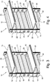
- Figure 1 illustrates a shelving unit 10 which comprises vertical uprights 11, back panels 12 and horizontal shelves 13 able to constitute a rest surface for the products to be displayed.
- the above-mentioned components are designed to define a shelving unit module having a pair of adjacent uprights 11 reciprocally facing at a distance equal to the length of the back panel, at least one back panel 12 (the back of the unit might in fact be made with only one panel extending over the whole height of the shelving unit, in particular when such height is not excessive, or with a plurality of panels having a smaller height, mounted sequentially one above the other) and at least one shelf 13 (the number of shelves can obviously vary according to the height of the shelving unit and the free space that is to be maintained between one shelf and another).
- the shelves 13 are supported by brackets 14 (clearly visible in the exploded view of Figure 2 ) provided at an end thereof with lugs for hooking into slots 15 present on the front face of each upright 11, as is well known to the skilled person.
- the shelving unit 10 can advantageously also comprise, at the lower end of the uprights 11, base brackets 14' provided with feet 16 for resting on a floor surface and adapted to support a base shelf 13', as shown in Figure 1 .
- the back panel 12 destined to be hooked in a vertical position to a pair of adjacent uprights 11, can be used to make the rear closure of a single-display shelving unit or a separating wall between two opposite display zones when constructing a double-fronted display shelving unit.
- the back panel 12 is provided, at side edges thereof, with hooking lugs 17, 17' projecting laterally with respect to the vertical extension plane of the panel.
- the lugs 17, 17' are hook-shaped, with respective vertical grooves open at the bottom in order to lock on the lower edge of slots of a slots arrangement 18 present in the side walls of the respective uprights so as to provide hanging of the back panel.
- the back panel 12 is made of fretted metal sheet, having a zigzag profile with an alternation of ribs 19, 19' arranged on two parallel planes offset with respect to each other.
- reference numeral 19 denotes the ribs projecting towards the front part of the shelving unit (i.e. towards the shelves) and 19' the ribs projecting towards the rear part of the shelving unit.
- front ribs 19 can also be identified as “convex ribs” and the rear ribs 19' as “concave ribs”, coherently with the configuration they present to an observer positioned in front of the shelving unit.
- the expressions "plane of front ribs” and “plane of rear ribs” of the back panel will be used respectively where these two parallel planes are offset with respect to one another by a predetermined distance.
- the uprights 11 are provided, at their side walls 20 (i.e. the walls designed to face the side wall of an adjacent upright in the shelving unit module), with a slots arrangement 18 for hanging the back panel 12 by means of the hooking lugs 17, 17'.
- the slots arrangement 18 comprises a first group of slots 21 extending vertically in a central position along the side wall 20 of each upright 11.
- This first group of central slots 21 can be constituted by a single vertical row of slots having a width substantially equal to the offset distance between the plane of the front ribs 19 of the back panel 12 and the plane of the rear ribs 19' for housing both the respective lugs 17, 17', or more advantageously, as also known in the art, said first group of central slots 21 can consist of a double vertical row of slots spaced by said offset distance and each having a width that is substantially equal to the thickness of a single lug of the back panel for enabling selective insertion of each series of lugs 17, 17' in a respective vertical row of slots.
- the slots arrangement 18 comprises at least one further group of slots 22 extending vertically in a lateral position with respect to said group of central slots 21, in proximity of one of the edges of the upright 11.
- This further group of slots 22 can consist of a vertical row of slots, advantageously arranged along the edge of the upright 11 destined to be rearward in the shelving unit, i.e. on the opposite side with respect to the shelves 13.
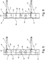
- FIGS 4 and 6 illustrate a mounting configuration of the back panel wherein the lugs of the back panel (or panels) 12 are inserted in the slots of said further group of lateral slots 22.
- This mounting configuration will be defined in the following as the "rear mounting configuration”.
- suitable extension elements 23, 23' can be included, having an appropriate different width (according to the chosen mounting configuration, central or rear) to be fastened, using connecting means 24 visible in Figure 2 , rearward of the shelves 13 for filling the empty space between the rear edge of the shelf (in fixed position, as being mounted on the brackets 14 hooked to the slots 15 present on the front face of the uprights) and the wall of the back panel 12.
- the shelves 13 can be mounted, at the desired height, both at the position of the convex ribs 19 of the back panel 12 (as, for example, the lower shelf in Figures 5 and 6 ) and at the position of the concave ribs 19' (as the upper shelf of Figures 5 and 6 ), in the latter case a small empty space can be present between the rear edge of the extension element 23, 23' and the wall of the back panel 12.
- this small empty space is fully acceptable, being generally of a dimension contained within about 1 cm.
- the slots arrangement 18 can also advantageously comprise a second further group of slots 22' extending vertically in proximity of the edge of the upright 11 opposite with respect to the edge along which the above-described first further group of slots 22 is arranged, i.e. the edge destined to be foreward in the shelving unit, on the side of the shelves 13.
- This second further group of slots 22' consisting of a vertical row of slots arranged along the front edge of the upright 11 can be seen in the accompanying figures.
- the presence of said second further group of slots 22' makes also possible, if desired, a further mounting configuration of the back panel wherein the lugs of the panel (or panels) of the back panel 12 are inserted in the slots of this further group of lateral slots 22', thus increasing the flexibility of use of the shelving unit.
- This mounting configuration of the back panel will be defined in the following as the "front mounting configuration".
- the extension element thought for the central and rear configurations previously described for filling the empty space up to the back panel might not be necessary.
- the further groups of slots 22, 22' might consist, if the dimensions of the upright allow it, of a double vertical row of slots spaced by the offset distance between the planes of the front and rear ribs of the back panel 12, so as to enable selective insertion of each series of lugs 17, 17' in a respective vertical row of slots as in the case of the group of central slots 21, even though groups of lateral slots 22, 22' consisting of only one row of slots can normally be preferable for reasons of greater economy and constructional simplicity of the uprights that this solution provides.
Landscapes
- Assembled Shelves (AREA)
- Display Racks (AREA)
- Finishing Walls (AREA)
Claims (9)
- Regalsystem, umfassend wenigstens ein Paar von vertikalen Stützen (11), die jeweils eine Seitenwand (20) aufweisen, die dazu bestimmt ist, der Seitenwand (20) der angrenzenden Stütze des Paares zugewandt zu sein, wenigstens eine Rückenplatte (12), die dazu geeignet ist, in vertikaler Position an den angrenzenden Stützen (11) des Paares von Stützen eingehängt zu werden, und wenigstens einen Regalboden (13), der an den Stützen (11) befestigt sein soll, wobei die Seitenwände (20) der Stützen (11) mit einer Schlitzanordnung (18) zum Einhängen der Rückenplatte (12) versehen sind und die Rückenplatte (12) an ihren Seitenkanten Einhakansätze (17, 17') aufweist, die seitlich auskragen, um in die auf den Seitenwänden (20) der Stützen (11) befindlichen Schlitze der Schlitzanordnung (18) einzugreifen, wobei die Schlitzanordnung (18) eine erste Gruppe von Schlitzen (21) umfasst, die sich vertikal in einer zentralen Position entlang der Seitenwand (20) der Stütze (11) erstrecken, dadurch gekennzeichnet, dass die Schlitzanordnung (18) wenigstens eine weitere Gruppe von Schlitzen (22) umfasst, die sich vertikal in einer seitlichen Position in Bezug auf die erste Gruppe von Schlitzen (21) entlang einer der Kanten der Stütze (11) erstrecken.
- Regalsystem nach Anspruch 1, dadurch gekennzeichnet, dass die Schlitzanordnung (18) auch eine weitere zweite Gruppe von Schlitzen (22') umfasst, die sich vertikal in einer seitlichen Position in Bezug auf die erste Gruppe von zentralen Schlitzen (21) entlang der Kante der Stütze (11) gegenüber jener Kante erstreckt, entlang der die wenigstens eine weitere Gruppe von Schlitzen (22) angeordnet ist.
- Regalsystem nach Anspruch 1, dadurch gekennzeichnet, dass die Rückenplatte (12) aus Trapezblech hergestellt ist, das ein Zickzackprofil mit einer Wechselfolge von Rippen (19, 19') aufweist, die auf zwei parallelen, zueinander versetzten Ebenen angeordnet sind, wobei jeweilige Einhakansätze (17, 17') aus den Rippen (19, 19') einer jeden Ebene auskragen.
- Regalsystem nach Anspruch 3, dadurch gekennzeichnet, dass die erste Gruppe von zentralen Schlitzen (21) aus einer vertikalen Doppelreihe von Schlitzen besteht, die durch den Versatzabstand der parallelen Ebenen, auf denen die Rippen (19, 19') der Rückenplatte (12) mit Zickzackprofil liegen, voneinander beabstandet sind, wobei die Einhakansätze (17, 17') der Rippen (19, 19') einer jeden Ebene sich wahlweise in die Schlitze einer der beiden vertikalen Reihen von Schlitzen einhängen.
- Regalsystem nach Anspruch 3, dadurch gekennzeichnet, dass die wenigstens eine weitere Gruppe von seitlichen Schlitzen (22) aus einer vertikalen Reihe von Schlitzen besteht, die zum Einhängen der Einhakansätze (17) der Rippen (19) geeignet sind, die auf der Ebene liegen, die der Mitte der Stütze (11) am nächsten gelegen ist, wobei die Einhakansätze (17') der anderen Rippen (19') auf einer in Bezug auf die Kante der Stütze (11) weiter außen liegenden Ebene bleiben.
- Regalsystem nach Anspruch 1, dadurch gekennzeichnet, dass es Verlängerungselemente (23, 23') zur Verlängerung der Regalböden (13) umfasst, die dazu geeignet sind, an dem Regalboden befestigt zu werden, um den Leerraum zwischen der hinteren Kante des Regelbodens (13) und der vertikalen Wand der Rückenplatte (12) auszufüllen.
- Regalsystem nach Anspruch 6, dadurch gekennzeichnet, dass die Verlängerungselemente (23, 23') unterschiedliche Breiten aufweisen, je nachdem, ob die Rückenplatte (12) durch Eingriff in die erste Gruppe von zentralen Schlitzen (21) oder durch Eingriff in die wenigstens eine weitere Gruppe von seitlichen Schlitzen (22) befestigt ist.
- Regalsystem nach Anspruch 1, dadurch gekennzeichnet, dass der wenigstens eine Regalboden (13) an den Stützen (11) durch Trägerkonsolen (14) befestigt ist, die an einem Ende mit Streifen zum Einhängen in Schlitze (15) versehen sind, die auf der Vorderfläche einer jeden Stütze (11) des Paares vorhanden sind.
- Verwendung eines Regalsystems nach Anspruch 1, wobei die Einhakposition der wenigstens einen Rückenplatte (12) an den Stützen (11) ausgewählt ist aus einer Anordnung mit Eingriff der Einhakansätze (17, 17') der Rückenplatte in der ersten Gruppe von zentralen Schlitzen (21) oder einer Anordnung mit Eingriff der Einhakansätze (17, 17') der Rückenplatte in die wenigstens eine weitere Gruppe von seitlichen Schlitzen (22).
Priority Applications (1)
| Application Number | Priority Date | Filing Date | Title |
|---|---|---|---|
| PL16179873T PL3120735T3 (pl) | 2015-07-22 | 2016-07-18 | Jednostka regałowa z regulowanym mocowaniem paneli tylnych |
Applications Claiming Priority (1)
| Application Number | Priority Date | Filing Date | Title |
|---|---|---|---|
| ITUB2015A002392A ITUB20152392A1 (it) | 2015-07-22 | 2015-07-22 | Gruppo di scaffalatura con montaggio regolabile dei pannelli di schienale. |
Publications (2)
| Publication Number | Publication Date |
|---|---|
| EP3120735A1 EP3120735A1 (de) | 2017-01-25 |
| EP3120735B1 true EP3120735B1 (de) | 2018-09-26 |
Family
ID=54289026
Family Applications (1)
| Application Number | Title | Priority Date | Filing Date |
|---|---|---|---|
| EP16179873.1A Active EP3120735B1 (de) | 2015-07-22 | 2016-07-18 | Regalsystem mit verstellbarer halterung der rückenplatten |
Country Status (6)
| Country | Link |
|---|---|
| EP (1) | EP3120735B1 (de) |
| ES (1) | ES2703187T3 (de) |
| IT (1) | ITUB20152392A1 (de) |
| LT (1) | LT3120735T (de) |
| PL (1) | PL3120735T3 (de) |
| TR (1) | TR201819519T4 (de) |
Cited By (1)
| Publication number | Priority date | Publication date | Assignee | Title |
|---|---|---|---|---|
| RU209795U1 (ru) * | 2021-02-19 | 2022-03-23 | Герман Юрьевич Лабазин | Металлический стеллаж |
Family Cites Families (4)
| Publication number | Priority date | Publication date | Assignee | Title |
|---|---|---|---|---|
| US3517623A (en) * | 1968-10-28 | 1970-06-30 | Butler Ind Inc | Rack system |
| GB2205378B (en) * | 1987-05-19 | 1991-05-15 | Clares Equip Ltd | Clip for shelving system |
| GB9604668D0 (en) * | 1996-03-05 | 1996-05-01 | Deniet & Sons Ltd | Metal panel structures |
| FR2874487B1 (fr) * | 2004-08-26 | 2009-03-27 | Hmy Investissements Sa | Panneau de fond pour mobilier metallique de rayonnages |
-
2015
- 2015-07-22 IT ITUB2015A002392A patent/ITUB20152392A1/it unknown
-
2016
- 2016-07-18 TR TR2018/19519T patent/TR201819519T4/tr unknown
- 2016-07-18 EP EP16179873.1A patent/EP3120735B1/de active Active
- 2016-07-18 LT LTEP16179873.1T patent/LT3120735T/lt unknown
- 2016-07-18 ES ES16179873T patent/ES2703187T3/es active Active
- 2016-07-18 PL PL16179873T patent/PL3120735T3/pl unknown
Non-Patent Citations (1)
| Title |
|---|
| None * |
Cited By (1)
| Publication number | Priority date | Publication date | Assignee | Title |
|---|---|---|---|---|
| RU209795U1 (ru) * | 2021-02-19 | 2022-03-23 | Герман Юрьевич Лабазин | Металлический стеллаж |
Also Published As
| Publication number | Publication date |
|---|---|
| ITUB20152392A1 (it) | 2017-01-22 |
| ES2703187T3 (es) | 2019-03-07 |
| LT3120735T (lt) | 2019-01-25 |
| TR201819519T4 (tr) | 2019-01-21 |
| PL3120735T3 (pl) | 2019-04-30 |
| EP3120735A1 (de) | 2017-01-25 |
Similar Documents
| Publication | Publication Date | Title |
|---|---|---|
| US11576503B2 (en) | Tiered display unit | |
| US9468312B2 (en) | Display fixture with cantilevered shelf | |
| US7775379B2 (en) | Retail display for greeting cards | |
| US5938048A (en) | Modular tiered rack assembly | |
| US8814108B2 (en) | Product display system | |
| AU2009329832B2 (en) | A shelving system | |
| US8782936B2 (en) | End frame for display structure | |
| DK2491827T3 (en) | Product delivery system for recording and presentation of goods | |
| US20130153524A1 (en) | Retrofitting system for shelves | |
| US2026223A (en) | Shelving | |
| RU2019131472A (ru) | Ящик для настенной системы хранения | |
| US3040904A (en) | Frame construction for racks with adjustable shelves | |
| EP3120735B1 (de) | Regalsystem mit verstellbarer halterung der rückenplatten | |
| US7980399B2 (en) | Modular display rack | |
| WO2004062439A1 (en) | Display system | |
| KR200482722Y1 (ko) | 셀 공간의 크기가 조절되는 상품 진열대 | |
| US10765233B2 (en) | Universal merchandising system | |
| US20120187813A1 (en) | Cabinet Conversion Panels | |
| KR102754744B1 (ko) | 전시용 선반 | |
| RU81416U1 (ru) | Компактный сборный стеллаж | |
| WO2015161875A1 (en) | Modular display system | |
| EP3323317B1 (de) | Schaukasten, insbesondere für laden | |
| ES2317822T3 (es) | Exhibidor de venta en autoservicio particularmente para productos lácteos y adaptable a un armario frigorífico. | |
| KR20220107145A (ko) | 거치 형태의 변경이 가능한 구조를 가지는 선반 | |
| NO328727B1 (no) | Opphengningsarrangement og fremgangsmate til fremstilling av dette |
Legal Events
| Date | Code | Title | Description |
|---|---|---|---|
| PUAI | Public reference made under article 153(3) epc to a published international application that has entered the european phase |
Free format text: ORIGINAL CODE: 0009012 |
|
| STAA | Information on the status of an ep patent application or granted ep patent |
Free format text: STATUS: THE APPLICATION HAS BEEN PUBLISHED |
|
| AK | Designated contracting states |
Kind code of ref document: A1 Designated state(s): AL AT BE BG CH CY CZ DE DK EE ES FI FR GB GR HR HU IE IS IT LI LT LU LV MC MK MT NL NO PL PT RO RS SE SI SK SM TR |
|
| AX | Request for extension of the european patent |
Extension state: BA ME |
|
| STAA | Information on the status of an ep patent application or granted ep patent |
Free format text: STATUS: REQUEST FOR EXAMINATION WAS MADE |
|
| 17P | Request for examination filed |
Effective date: 20170720 |
|
| RBV | Designated contracting states (corrected) |
Designated state(s): AL AT BE BG CH CY CZ DE DK EE ES FI FR GB GR HR HU IE IS IT LI LT LU LV MC MK MT NL NO PL PT RO RS SE SI SK SM TR |
|
| GRAP | Despatch of communication of intention to grant a patent |
Free format text: ORIGINAL CODE: EPIDOSNIGR1 |
|
| STAA | Information on the status of an ep patent application or granted ep patent |
Free format text: STATUS: GRANT OF PATENT IS INTENDED |
|
| INTG | Intention to grant announced |
Effective date: 20180502 |
|
| GRAS | Grant fee paid |
Free format text: ORIGINAL CODE: EPIDOSNIGR3 |
|
| GRAA | (expected) grant |
Free format text: ORIGINAL CODE: 0009210 |
|
| STAA | Information on the status of an ep patent application or granted ep patent |
Free format text: STATUS: THE PATENT HAS BEEN GRANTED |
|
| AK | Designated contracting states |
Kind code of ref document: B1 Designated state(s): AL AT BE BG CH CY CZ DE DK EE ES FI FR GB GR HR HU IE IS IT LI LT LU LV MC MK MT NL NO PL PT RO RS SE SI SK SM TR |
|
| REG | Reference to a national code |
Ref country code: GB Ref legal event code: FG4D |
|
| REG | Reference to a national code |
Ref country code: CH Ref legal event code: EP |
|
| REG | Reference to a national code |
Ref country code: AT Ref legal event code: REF Ref document number: 1045008 Country of ref document: AT Kind code of ref document: T Effective date: 20181015 |
|
| REG | Reference to a national code |
Ref country code: IE Ref legal event code: FG4D |
|
| REG | Reference to a national code |
Ref country code: DE Ref legal event code: R096 Ref document number: 602016005932 Country of ref document: DE |
|
| REG | Reference to a national code |
Ref country code: NL Ref legal event code: MP Effective date: 20180926 |
|
| PG25 | Lapsed in a contracting state [announced via postgrant information from national office to epo] |
Ref country code: FI Free format text: LAPSE BECAUSE OF FAILURE TO SUBMIT A TRANSLATION OF THE DESCRIPTION OR TO PAY THE FEE WITHIN THE PRESCRIBED TIME-LIMIT Effective date: 20180926 Ref country code: BG Free format text: LAPSE BECAUSE OF FAILURE TO SUBMIT A TRANSLATION OF THE DESCRIPTION OR TO PAY THE FEE WITHIN THE PRESCRIBED TIME-LIMIT Effective date: 20181226 Ref country code: RS Free format text: LAPSE BECAUSE OF FAILURE TO SUBMIT A TRANSLATION OF THE DESCRIPTION OR TO PAY THE FEE WITHIN THE PRESCRIBED TIME-LIMIT Effective date: 20180926 Ref country code: NO Free format text: LAPSE BECAUSE OF FAILURE TO SUBMIT A TRANSLATION OF THE DESCRIPTION OR TO PAY THE FEE WITHIN THE PRESCRIBED TIME-LIMIT Effective date: 20181226 Ref country code: GR Free format text: LAPSE BECAUSE OF FAILURE TO SUBMIT A TRANSLATION OF THE DESCRIPTION OR TO PAY THE FEE WITHIN THE PRESCRIBED TIME-LIMIT Effective date: 20181227 |
|
| REG | Reference to a national code |
Ref country code: SE Ref legal event code: TRGR |
|
| PG25 | Lapsed in a contracting state [announced via postgrant information from national office to epo] |
Ref country code: HR Free format text: LAPSE BECAUSE OF FAILURE TO SUBMIT A TRANSLATION OF THE DESCRIPTION OR TO PAY THE FEE WITHIN THE PRESCRIBED TIME-LIMIT Effective date: 20180926 Ref country code: LV Free format text: LAPSE BECAUSE OF FAILURE TO SUBMIT A TRANSLATION OF THE DESCRIPTION OR TO PAY THE FEE WITHIN THE PRESCRIBED TIME-LIMIT Effective date: 20180926 Ref country code: AL Free format text: LAPSE BECAUSE OF FAILURE TO SUBMIT A TRANSLATION OF THE DESCRIPTION OR TO PAY THE FEE WITHIN THE PRESCRIBED TIME-LIMIT Effective date: 20180926 |
|
| REG | Reference to a national code |
Ref country code: ES Ref legal event code: FG2A Ref document number: 2703187 Country of ref document: ES Kind code of ref document: T3 Effective date: 20190307 |
|
| REG | Reference to a national code |
Ref country code: AT Ref legal event code: MK05 Ref document number: 1045008 Country of ref document: AT Kind code of ref document: T Effective date: 20180926 |
|
| PG25 | Lapsed in a contracting state [announced via postgrant information from national office to epo] |
Ref country code: IS Free format text: LAPSE BECAUSE OF FAILURE TO SUBMIT A TRANSLATION OF THE DESCRIPTION OR TO PAY THE FEE WITHIN THE PRESCRIBED TIME-LIMIT Effective date: 20190126 Ref country code: AT Free format text: LAPSE BECAUSE OF FAILURE TO SUBMIT A TRANSLATION OF THE DESCRIPTION OR TO PAY THE FEE WITHIN THE PRESCRIBED TIME-LIMIT Effective date: 20180926 Ref country code: RO Free format text: LAPSE BECAUSE OF FAILURE TO SUBMIT A TRANSLATION OF THE DESCRIPTION OR TO PAY THE FEE WITHIN THE PRESCRIBED TIME-LIMIT Effective date: 20180926 Ref country code: CZ Free format text: LAPSE BECAUSE OF FAILURE TO SUBMIT A TRANSLATION OF THE DESCRIPTION OR TO PAY THE FEE WITHIN THE PRESCRIBED TIME-LIMIT Effective date: 20180926 Ref country code: NL Free format text: LAPSE BECAUSE OF FAILURE TO SUBMIT A TRANSLATION OF THE DESCRIPTION OR TO PAY THE FEE WITHIN THE PRESCRIBED TIME-LIMIT Effective date: 20180926 Ref country code: EE Free format text: LAPSE BECAUSE OF FAILURE TO SUBMIT A TRANSLATION OF THE DESCRIPTION OR TO PAY THE FEE WITHIN THE PRESCRIBED TIME-LIMIT Effective date: 20180926 |
|
| PG25 | Lapsed in a contracting state [announced via postgrant information from national office to epo] |
Ref country code: SM Free format text: LAPSE BECAUSE OF FAILURE TO SUBMIT A TRANSLATION OF THE DESCRIPTION OR TO PAY THE FEE WITHIN THE PRESCRIBED TIME-LIMIT Effective date: 20180926 Ref country code: PT Free format text: LAPSE BECAUSE OF FAILURE TO SUBMIT A TRANSLATION OF THE DESCRIPTION OR TO PAY THE FEE WITHIN THE PRESCRIBED TIME-LIMIT Effective date: 20190126 Ref country code: SK Free format text: LAPSE BECAUSE OF FAILURE TO SUBMIT A TRANSLATION OF THE DESCRIPTION OR TO PAY THE FEE WITHIN THE PRESCRIBED TIME-LIMIT Effective date: 20180926 |
|
| REG | Reference to a national code |
Ref country code: DE Ref legal event code: R097 Ref document number: 602016005932 Country of ref document: DE |
|
| PG25 | Lapsed in a contracting state [announced via postgrant information from national office to epo] |
Ref country code: DK Free format text: LAPSE BECAUSE OF FAILURE TO SUBMIT A TRANSLATION OF THE DESCRIPTION OR TO PAY THE FEE WITHIN THE PRESCRIBED TIME-LIMIT Effective date: 20180926 |
|
| PLBE | No opposition filed within time limit |
Free format text: ORIGINAL CODE: 0009261 |
|
| STAA | Information on the status of an ep patent application or granted ep patent |
Free format text: STATUS: NO OPPOSITION FILED WITHIN TIME LIMIT |
|
| 26N | No opposition filed |
Effective date: 20190627 |
|
| PG25 | Lapsed in a contracting state [announced via postgrant information from national office to epo] |
Ref country code: SI Free format text: LAPSE BECAUSE OF FAILURE TO SUBMIT A TRANSLATION OF THE DESCRIPTION OR TO PAY THE FEE WITHIN THE PRESCRIBED TIME-LIMIT Effective date: 20180926 |
|
| PG25 | Lapsed in a contracting state [announced via postgrant information from national office to epo] |
Ref country code: MC Free format text: LAPSE BECAUSE OF FAILURE TO SUBMIT A TRANSLATION OF THE DESCRIPTION OR TO PAY THE FEE WITHIN THE PRESCRIBED TIME-LIMIT Effective date: 20180926 |
|
| REG | Reference to a national code |
Ref country code: CH Ref legal event code: PL |
|
| REG | Reference to a national code |
Ref country code: BE Ref legal event code: MM Effective date: 20190731 |
|
| PG25 | Lapsed in a contracting state [announced via postgrant information from national office to epo] |
Ref country code: LI Free format text: LAPSE BECAUSE OF NON-PAYMENT OF DUE FEES Effective date: 20190731 Ref country code: LU Free format text: LAPSE BECAUSE OF NON-PAYMENT OF DUE FEES Effective date: 20190718 Ref country code: CH Free format text: LAPSE BECAUSE OF NON-PAYMENT OF DUE FEES Effective date: 20190731 Ref country code: BE Free format text: LAPSE BECAUSE OF NON-PAYMENT OF DUE FEES Effective date: 20190731 |
|
| PG25 | Lapsed in a contracting state [announced via postgrant information from national office to epo] |
Ref country code: IE Free format text: LAPSE BECAUSE OF NON-PAYMENT OF DUE FEES Effective date: 20190718 |
|
| PG25 | Lapsed in a contracting state [announced via postgrant information from national office to epo] |
Ref country code: CY Free format text: LAPSE BECAUSE OF FAILURE TO SUBMIT A TRANSLATION OF THE DESCRIPTION OR TO PAY THE FEE WITHIN THE PRESCRIBED TIME-LIMIT Effective date: 20180926 |
|
| PG25 | Lapsed in a contracting state [announced via postgrant information from national office to epo] |
Ref country code: HU Free format text: LAPSE BECAUSE OF FAILURE TO SUBMIT A TRANSLATION OF THE DESCRIPTION OR TO PAY THE FEE WITHIN THE PRESCRIBED TIME-LIMIT; INVALID AB INITIO Effective date: 20160718 Ref country code: MT Free format text: LAPSE BECAUSE OF FAILURE TO SUBMIT A TRANSLATION OF THE DESCRIPTION OR TO PAY THE FEE WITHIN THE PRESCRIBED TIME-LIMIT Effective date: 20180926 |
|
| PG25 | Lapsed in a contracting state [announced via postgrant information from national office to epo] |
Ref country code: MK Free format text: LAPSE BECAUSE OF FAILURE TO SUBMIT A TRANSLATION OF THE DESCRIPTION OR TO PAY THE FEE WITHIN THE PRESCRIBED TIME-LIMIT Effective date: 20180926 |
|
| P01 | Opt-out of the competence of the unified patent court (upc) registered |
Effective date: 20230531 |
|
| PGFP | Annual fee paid to national office [announced via postgrant information from national office to epo] |
Ref country code: LT Payment date: 20230605 Year of fee payment: 8 |
|
| PGFP | Annual fee paid to national office [announced via postgrant information from national office to epo] |
Ref country code: PL Payment date: 20230629 Year of fee payment: 8 |
|
| PGFP | Annual fee paid to national office [announced via postgrant information from national office to epo] |
Ref country code: TR Payment date: 20230703 Year of fee payment: 8 Ref country code: GB Payment date: 20230711 Year of fee payment: 8 Ref country code: ES Payment date: 20230807 Year of fee payment: 8 |
|
| PGFP | Annual fee paid to national office [announced via postgrant information from national office to epo] |
Ref country code: SE Payment date: 20230713 Year of fee payment: 8 Ref country code: FR Payment date: 20230710 Year of fee payment: 8 Ref country code: DE Payment date: 20230710 Year of fee payment: 8 |
|
| REG | Reference to a national code |
Ref country code: DE Ref legal event code: R119 Ref document number: 602016005932 Country of ref document: DE |
|
| REG | Reference to a national code |
Ref country code: LT Ref legal event code: MM4D Effective date: 20240718 |
|
| REG | Reference to a national code |
Ref country code: SE Ref legal event code: EUG |
|
| GBPC | Gb: european patent ceased through non-payment of renewal fee |
Effective date: 20240718 |
|
| PG25 | Lapsed in a contracting state [announced via postgrant information from national office to epo] |
Ref country code: DE Free format text: LAPSE BECAUSE OF NON-PAYMENT OF DUE FEES Effective date: 20250201 |
|
| PG25 | Lapsed in a contracting state [announced via postgrant information from national office to epo] |
Ref country code: LT Free format text: LAPSE BECAUSE OF NON-PAYMENT OF DUE FEES Effective date: 20240718 |
|
| PG25 | Lapsed in a contracting state [announced via postgrant information from national office to epo] |
Ref country code: FR Free format text: LAPSE BECAUSE OF NON-PAYMENT OF DUE FEES Effective date: 20240731 |
|
| PG25 | Lapsed in a contracting state [announced via postgrant information from national office to epo] |
Ref country code: GB Free format text: LAPSE BECAUSE OF NON-PAYMENT OF DUE FEES Effective date: 20240718 |
|
| REG | Reference to a national code |
Ref country code: ES Ref legal event code: FD2A Effective date: 20250829 |
|
| PG25 | Lapsed in a contracting state [announced via postgrant information from national office to epo] |
Ref country code: ES Free format text: LAPSE BECAUSE OF NON-PAYMENT OF DUE FEES Effective date: 20240719 |
|
| PG25 | Lapsed in a contracting state [announced via postgrant information from national office to epo] |
Ref country code: SE Free format text: LAPSE BECAUSE OF NON-PAYMENT OF DUE FEES Effective date: 20240719 |
|
| PG25 | Lapsed in a contracting state [announced via postgrant information from national office to epo] |
Ref country code: PL Free format text: LAPSE BECAUSE OF NON-PAYMENT OF DUE FEES Effective date: 20240718 |
|
| PGFP | Annual fee paid to national office [announced via postgrant information from national office to epo] |
Ref country code: IT Payment date: 20260324 Year of fee payment: 11 |