EP3120628B1 - Compressed mode with dch enhancements - Google Patents
Compressed mode with dch enhancements Download PDFInfo
- Publication number
- EP3120628B1 EP3120628B1 EP15703675.7A EP15703675A EP3120628B1 EP 3120628 B1 EP3120628 B1 EP 3120628B1 EP 15703675 A EP15703675 A EP 15703675A EP 3120628 B1 EP3120628 B1 EP 3120628B1
- Authority
- EP
- European Patent Office
- Prior art keywords
- downlink
- during
- compression interval
- dpch
- slots
- Prior art date
- Legal status (The legal status is an assumption and is not a legal conclusion. Google has not performed a legal analysis and makes no representation as to the accuracy of the status listed.)
- Active
Links
- 230000005540 biological transmission Effects 0.000 claims description 334
- 230000006835 compression Effects 0.000 claims description 160
- 238000007906 compression Methods 0.000 claims description 160
- 238000000034 method Methods 0.000 claims description 81
- 238000004891 communication Methods 0.000 claims description 56
- 108010003272 Hyaluronate lyase Proteins 0.000 claims description 42
- 230000007480 spreading Effects 0.000 claims description 6
- 238000013507 mapping Methods 0.000 description 42
- 238000010586 diagram Methods 0.000 description 21
- 238000012545 processing Methods 0.000 description 16
- 230000006870 function Effects 0.000 description 14
- 230000011664 signaling Effects 0.000 description 11
- 238000005516 engineering process Methods 0.000 description 10
- 238000005259 measurement Methods 0.000 description 8
- 238000013461 design Methods 0.000 description 5
- 230000008569 process Effects 0.000 description 4
- 238000010295 mobile communication Methods 0.000 description 3
- 230000009467 reduction Effects 0.000 description 3
- 238000001228 spectrum Methods 0.000 description 3
- 230000003044 adaptive effect Effects 0.000 description 2
- 238000003491 array Methods 0.000 description 2
- 230000001413 cellular effect Effects 0.000 description 2
- 230000008859 change Effects 0.000 description 2
- 239000003795 chemical substances by application Substances 0.000 description 2
- 238000004590 computer program Methods 0.000 description 2
- 230000003750 conditioning effect Effects 0.000 description 2
- 125000004122 cyclic group Chemical group 0.000 description 2
- 238000001514 detection method Methods 0.000 description 2
- 238000001914 filtration Methods 0.000 description 2
- 230000015654 memory Effects 0.000 description 2
- 238000012986 modification Methods 0.000 description 2
- 230000004048 modification Effects 0.000 description 2
- 230000008520 organization Effects 0.000 description 2
- 230000002093 peripheral effect Effects 0.000 description 2
- 230000010363 phase shift Effects 0.000 description 2
- 208000037918 transfusion-transmitted disease Diseases 0.000 description 2
- NUOYJPPISCCYDH-BYPYZUCNSA-N (2s)-1-(2,2,2-trifluoroacetyl)pyrrolidine-2-carbonyl chloride Chemical compound FC(F)(F)C(=O)N1CCC[C@H]1C(Cl)=O NUOYJPPISCCYDH-BYPYZUCNSA-N 0.000 description 1
- 230000003321 amplification Effects 0.000 description 1
- 230000002457 bidirectional effect Effects 0.000 description 1
- 230000033228 biological regulation Effects 0.000 description 1
- 238000012937 correction Methods 0.000 description 1
- 230000001419 dependent effect Effects 0.000 description 1
- 238000005562 fading Methods 0.000 description 1
- 230000002349 favourable effect Effects 0.000 description 1
- 230000000977 initiatory effect Effects 0.000 description 1
- 230000007774 longterm Effects 0.000 description 1
- 238000003199 nucleic acid amplification method Methods 0.000 description 1
- 230000003287 optical effect Effects 0.000 description 1
- 239000005022 packaging material Substances 0.000 description 1
- 238000012827 research and development Methods 0.000 description 1
- 238000012552 review Methods 0.000 description 1
- 230000011218 segmentation Effects 0.000 description 1
- 238000012546 transfer Methods 0.000 description 1
- 230000007704 transition Effects 0.000 description 1
Images


Classifications
-
- H—ELECTRICITY
- H04—ELECTRIC COMMUNICATION TECHNIQUE
- H04W—WIRELESS COMMUNICATION NETWORKS
- H04W52/00—Power management, e.g. TPC [Transmission Power Control], power saving or power classes
- H04W52/04—TPC
- H04W52/30—TPC using constraints in the total amount of available transmission power
- H04W52/36—TPC using constraints in the total amount of available transmission power with a discrete range or set of values, e.g. step size, ramping or offsets
-
- H—ELECTRICITY
- H04—ELECTRIC COMMUNICATION TECHNIQUE
- H04W—WIRELESS COMMUNICATION NETWORKS
- H04W52/00—Power management, e.g. TPC [Transmission Power Control], power saving or power classes
- H04W52/04—TPC
- H04W52/18—TPC being performed according to specific parameters
- H04W52/24—TPC being performed according to specific parameters using SIR [Signal to Interference Ratio] or other wireless path parameters
- H04W52/241—TPC being performed according to specific parameters using SIR [Signal to Interference Ratio] or other wireless path parameters taking into account channel quality metrics, e.g. SIR, SNR, CIR, Eb/lo
-
- H—ELECTRICITY
- H04—ELECTRIC COMMUNICATION TECHNIQUE
- H04L—TRANSMISSION OF DIGITAL INFORMATION, e.g. TELEGRAPHIC COMMUNICATION
- H04L1/00—Arrangements for detecting or preventing errors in the information received
- H04L1/12—Arrangements for detecting or preventing errors in the information received by using return channel
- H04L1/16—Arrangements for detecting or preventing errors in the information received by using return channel in which the return channel carries supervisory signals, e.g. repetition request signals
- H04L1/18—Automatic repetition systems, e.g. Van Duuren systems
- H04L1/1829—Arrangements specially adapted for the receiver end
- H04L1/1854—Scheduling and prioritising arrangements
-
- H—ELECTRICITY
- H04—ELECTRIC COMMUNICATION TECHNIQUE
- H04L—TRANSMISSION OF DIGITAL INFORMATION, e.g. TELEGRAPHIC COMMUNICATION
- H04L5/00—Arrangements affording multiple use of the transmission path
- H04L5/003—Arrangements for allocating sub-channels of the transmission path
- H04L5/0053—Allocation of signaling, i.e. of overhead other than pilot signals
- H04L5/0055—Physical resource allocation for ACK/NACK
-
- H—ELECTRICITY
- H04—ELECTRIC COMMUNICATION TECHNIQUE
- H04L—TRANSMISSION OF DIGITAL INFORMATION, e.g. TELEGRAPHIC COMMUNICATION
- H04L5/00—Arrangements affording multiple use of the transmission path
- H04L5/003—Arrangements for allocating sub-channels of the transmission path
- H04L5/0058—Allocation criteria
- H04L5/006—Quality of the received signal, e.g. BER, SNR, water filling
-
- H—ELECTRICITY
- H04—ELECTRIC COMMUNICATION TECHNIQUE
- H04W—WIRELESS COMMUNICATION NETWORKS
- H04W52/00—Power management, e.g. TPC [Transmission Power Control], power saving or power classes
- H04W52/04—TPC
- H04W52/06—TPC algorithms
- H04W52/14—Separate analysis of uplink or downlink
- H04W52/146—Uplink power control
-
- H—ELECTRICITY
- H04—ELECTRIC COMMUNICATION TECHNIQUE
- H04W—WIRELESS COMMUNICATION NETWORKS
- H04W72/00—Local resource management
- H04W72/04—Wireless resource allocation
- H04W72/044—Wireless resource allocation based on the type of the allocated resource
- H04W72/0446—Resources in time domain, e.g. slots or frames
-
- H—ELECTRICITY
- H04—ELECTRIC COMMUNICATION TECHNIQUE
- H04B—TRANSMISSION
- H04B1/00—Details of transmission systems, not covered by a single one of groups H04B3/00 - H04B13/00; Details of transmission systems not characterised by the medium used for transmission
- H04B1/69—Spread spectrum techniques
- H04B1/707—Spread spectrum techniques using direct sequence modulation
-
- H—ELECTRICITY
- H04—ELECTRIC COMMUNICATION TECHNIQUE
- H04J—MULTIPLEX COMMUNICATION
- H04J13/00—Code division multiplex systems
Definitions
- aspects of the present disclosure relate generally to wireless communication systems, and more particularly, to physical layer configuration of wireless communications.
- Wireless communication networks are widely deployed to provide various communication services such as telephony, video, data, messaging, broadcasts, and so on.
- Such networks which are usually multiple access networks, support communications for multiple users by sharing the available network resources.
- UTRAN UMTS Terrestrial Radio Access Network
- the UTRAN is the radio access network (RAN) defined as a part of the Universal Mobile Telecommunications System (UMTS), a third generation (3G) mobile phone technology supported by the 3rd Generation Partnership Project (3GPP).
- UMTS Universal Mobile Telecommunications System
- 3GPP 3rd Generation Partnership Project
- the UMTS which is the successor to Global System for Mobile Communications (GSM) technologies, currently supports various air interface standards, such as Wideband-Code Division Multiple Access (W-CDMA), Time Division-Code Division Multiple Access (TD-CDMA), and Time Division-Synchronous Code Division Multiple Access (TD-SCDMA).
- W-CDMA Wideband-Code Division Multiple Access
- TD-CDMA Time Division-Code Division Multiple Access
- TD-SCDMA Time Division-Synchronous Code Division Multiple Access
- the UMTS also supports enhanced 3G data communications protocols, such as High Speed Packet Access (HSPA), which provides higher data transfer speeds and capacity to associated UMTS networks.
- HSPA High Speed Packet Access
- Release-99 is a standard that defined dedicated channels between a user equipment (UE) and a base station or node B based on orthogonal variable spreading factor (OVSF) codes.
- Some wireless networks continue to rely on Release-99 channels for various services.
- a voice call may be carried over a Release-99 dedicated channel (DCH).
- DCH Release-99 dedicated channel
- Release-99 channels allow for a compressed mode (CM) operation to allow a UE to perform measurements on another frequency or another radio access technology (RAT).
- CM compressed mode
- the Release-99 CM operation may reduce a spreading factor for a DCH.
- Such spreading factor reduction may present difficulties for network management of a code tree or may result in additional interference when non-orthogonal codes are used.
- alternative methods of compressed mode operation are desirable.
- WO 2006/006895 A1 describes a method and apparatus for adjusting a transmit power control process in a mobile radio communications system.
- a user equipment may receiving a downlink dedicated physical channel (DPCH) having a slot-format and a spreading factor during a first compression interval.
- the downlink DPCH may not include a compressed-mode transmission gap during the first compression interval.
- the UE may receive the downlink DPCH having the same slot-format and the same spreading factor during a second compression interval.
- the UE may determine that the downlink DPCH includes a compressed-mode transmission gap during the second compression interval.
- a set of slots of the downlink DPCH during the transmission gap may be punctured.
- the UE may decode the downlink DPCH for the second compression interval based on a set of remaining slots received during the second compression interval.
- the UE may estimate a SIR based on a TPC command in a last slot of the transmission gap.
- the disclosure provides a method of providing a compressed mode transmission gap in wireless communications.
- the method may include receiving a downlink dedicated physical channel DPCH having a slot-format and a spreading factor during a first compression interval, wherein the downlink DPCH does not include a compressed-mode transmission gap during the first compression interval.
- the method may further include receiving the downlink DPCH having the same slot-format and the same spreading factor during a second compression interval.
- the method may also include determining that the downlink DPCH includes a compressed-mode transmission gap during the second compression interval, wherein a set of slots of the downlink DPCH during the transmission gap are punctured.
- the method may additionally include decoding the downlink DPCH for the second compression interval based on a set of remaining slots received during the second compression interval.
- the disclosure includes an apparatus for providing a compressed mode transmission gap in wireless communications.
- the apparatus may include a receiver configured to receive a downlink dedicated physical channel (DPCH) having a slot-format and a spreading factor during a first compression interval, wherein the downlink DPCH does not include a compressed-mode transmission gap during the first compression interval, and receive the downlink DPCH having the same slot-format and the same spreading factor during a second compression interval.
- the apparatus may further include a transmit gap component configured to determine that the downlink DPCH includes a compressed-mode transmission gap during the second compression interval, wherein a set of slots of the downlink DPCH during the transmission gap are punctured.
- the apparatus may also include a decoder configured to decode the downlink DPCH for the second compression interval based on a set of remaining slots received during the second compression interval.
- the disclose includes another apparatus for providing a compressed mode transmission gap in wireless communications.
- the apparatus may include means for receiving a downlink DPCH having a slot-format and a spreading factor during a first compression interval, wherein the downlink DPCH does not include a compressed-mode transmission gap during the first compression interval.
- the apparatus may further include means for receiving the downlink DPCH having the same slot-format and the same spreading factor during a second compression interval.
- the apparatus may also include means for determining that the downlink DPCH includes a compressed-mode transmission gap during the second compression interval, wherein a set of slots of the downlink DPCH during the transmission gap are punctured.
- the apparatus may additionally include means for decoding the downlink DPCH for the second compression interval based on a set of remaining slots received during the second compression interval.
- the a computer-readable medium may include code for receiving a downlink DPCH having a slot-format and a spreading factor during a first compression interval, wherein the downlink DPCH does not include a compressed-mode transmission gap during the first compression interval.
- the computer-readable medium may also include code for receiving the downlink DPCH having the same slot-format and the same spreading factor during a second compression interval.
- the computer-readable medium may further include code for determining that the downlink DPCH includes a compressed-mode transmission gap during the second compression interval, wherein a set of slots of the downlink DPCH during the transmission gap are punctured.
- the computer-readable medium may additionally include code for decoding the downlink DPCH for the second compression interval based on a set of remaining slots received during the second compression interval.
- the computer-readable medium may be a non-transitory computer-readable medium.
- Release-99 channels are still used.
- Release-99 dedicated channels are often used for voice calls due to channel reliability.
- a voice call is transmitted as 20 millisecond (ms) voice packets carried over a Release-99 dedicated channel (DCH) having a 20 ms transmit time interval (TTI).
- DCH Release-99 dedicated channel
- TTI transmit time interval
- Recent enhancements to the Release-99 DCH are designed to conserve resources such as battery life and improve network capacity.
- Pseudo-flexible rate matching may be used to improve efficiency of physical channel bit allocation by reducing bits for a signaling radio bearer (SRB) sub-flow when no signaling is being transmitted.
- the transmit power may be increased to compensate for coding rate increases when the SRB is transmitted.
- the DCH may also be enhanced by creating opportunities to turn off a receiver or transmitter.
- a dedicated physical data channel may be compressed at the physical layer such that data normally sent over the 20 ms TTI may be sent over a 10 ms TTI, and the transmitter and receiver may be turned off during another 10 ms period.
- the compression may use a higher peak power, so a UE may switch between a 10 ms TTI mode and 20 ms TTI mode based on transmit power headroom.
- Transport format combination indicator (TFCI) bits may be transmitted in the uplink to signal the mode and help decode the transmission.
- FET frame early detection
- FET may include multiple attempts to decode the downlink DPDCH before the transmission is completed.
- an acknowledgment may be sent on the uplink, and the remaining portion of a TTI may be set to discontinuous transmission (DTX) or discontinuous receive (DRX).
- DTX discontinuous transmission
- DRX discontinuous receive
- compressed mode may be configured using the above enhancements to Release-99 DCH.
- the DPCH may use the same slot format and spreading factor for every compression interval.
- a compression interval including a transmission gap may have the same slot format and spreading factor as a compression interval with no transmission gap.
- Discontinuous transmission (DTX) may be used during the transmission gap.
- the UE may decode the DPCH based on the remaining slots of the DPCH that are transmitted.
- a transmit power control (TPC) command may be transmitted at the end of each slot.
- a TPC command having a fixed value may be transmitted at the end of the last slot of a transmission gap.
- a UE may use the TPC command having a fixed value to estimate a SIR.
- compressed mode for the downlink DPCH may be implemented without other DCH enhancements.
- the downlink DPCH may always use a 20 ms TTI without FET.
- a transmission may be mapped to slots excluding slots of the compressed mode transmission gap.
- the transmission may use slots both before and after the compressed mode transmission gap but not the slots for the compressed mode transmission gap.
- the TFCI bits may mapped to transmitted slots such that the TFCI bits are transmitted without puncturing.
- An FET ACK/NAK field may take the place of the TFCI bits in a TTI once all of the TFCI bits have been transmitted
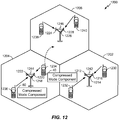
- a wireless communication system 10 includes at least one UE 12 in communication coverage of at least one network entity 14 (e.g., base station or Node B), wherein the UE 12 includes a compressed mode component 40 for providing transmission gaps on a DCH.
- the network entity 14 may also include a corresponding compressed mode component 60 for providing transmission gaps on the DCH.
- the UE 12 may communicate with network 18 via network entity 14 and radio network controller (RNC) 16.
- RNC radio network controller
- multiple UEs including UE 12 may be in communication coverage with one or more network entities, including network entity 14.
- UE 12 may transmit and/or receive wireless communications to and/or from network entity 14.
- the RNC 16 may control communication between the UE 12 and one or more network entities 14.
- the RNC 16 may determine characteristics of the compressed mode to be implemented by the UE 12 and a network entity 14.
- UE 12 may also be referred to by those skilled in the art (as well as interchangeably herein) as a mobile station, a subscriber station, a mobile unit, a subscriber unit, a wireless unit, a remote unit, a mobile device, a wireless device, a wireless communications device, a remote device, a mobile subscriber station, an access terminal, a mobile terminal, a wireless terminal, a remote terminal, a handset, a terminal, a user agent, a mobile client, a client, a device for the Internet of Things, or some other suitable terminology.
- network entity 14 may be a macrocell, picocell, femtocell, relay, Node B, mobile Node B, UE (e.g., communicating in peer-to-peer or ad-hoc mode with UE 12), or substantially any type of component that can communicate with UE 12 to provide wireless network access at the UE 12.
- the network entity 14 may be a base station such as a Node B in an UTRA network.
- the network entity 14 may communicate directly with the network 18, or may communicate via the radio network controller (RNC) 16.
- the network entity 14 and/or the RNC 16 may include a peer compressed mode component 60 for communication with the UE 12.
- UE 12 may transmit and/or receive wireless communications 20 to and/or from network entity 14.
- wireless communications 20 may be, for example, a dedicated channel (DCH) between the UE 12 and a network entity 14.
- the DCH may include a dedicated physical channel (DPCH).
- the DPCH may include a dedicated physical data channel (DPDCH) and/or a dedicated physical control channel (DPCCH).
- DPDCH dedicated physical data channel
- DPCCH dedicated physical control channel
- a wireless device such as the UE 12 may include a modem component 30, which may be configured to manage wireless communications 20.
- the modem component 30 may be operable to handle compressed mode operation using DCH enhancements.
- the term "component" as used herein may be one of the parts that make up a system, may be hardware, firmware, and/or software that may be executed by the hardware, and may be divided into other components.
- the modem component 30 may include a radio resource control (RRC) component 32 that controls higher layer signaling between the UE 12 and the RNC 16, a transmitter 34 for transmitting radio signals, a receiver 36 for receiving radio signals, and a compressed mode component 40 for managing physical layer communications.
- RRC radio resource control
- the RRC component 32 may include hardware or means for implementing a RRC protocol.
- the RRC component 32 may include or be executable by a processor executing firmware or software for implementing a RRC protocol.
- the RRC protocol may be described in, for example, 3GPP TS 25.331.
- the RRC component 32 may receive signaling for a compressed mode operation.
- the RRC component 32 may receive a message including a DPCH compressed mode info information element (IE).
- IE DPCH compressed mode info information element
- the DPCH compressed mode IE may include, for example, a transmission gap pattern sequence (TGPS), transmission gap measurement purpose (TGMP), a transmission gap starting slot number (TGSN), one or more transmission gap lengths (TGL), a transmission gap distance (TGD), a transmission gap pattern length (TGPL), power offsets, and/or other information from the network defining compressed mode transmission gaps to be implemented by the UE 12.
- TGPS transmission gap pattern sequence
- TGMP transmission gap measurement purpose
- TGSN transmission gap starting slot number
- TGL transmission gap length
- TGL transmission gap distance
- TGPL transmission gap pattern length
- power offsets and/or other information from the network defining compressed mode transmission gaps to be implemented by the UE 12.
- the compressed mode configuration may be restricted to prevent transmission gaps from causing over-puncturing of DL DPCH.
- the compressed mode configuration may be restricted to allow no more than 15 slots of transmission gaps in a 40 ms period.
- the transmitter 34 may include hardware for transmitting a wireless radio frequency (RF) signal.
- the transmitter 34 may include transmit chain components such as an antenna, a transmitter, a digital-to-analog converter, and filters.
- the transmitter 34 may include a modulator and/or similar device when, for example, such components are not included in a modem.
- the transmitter 34 may be tuned to a frequency used by the network entity 14 or another base station.
- the receiver 36 may include hardware for receiving a wireless RF signal.
- the receiver 36 may include receive chain components such as an antenna, analog-to-digital converter, and filters.
- the receiver 36 may include a demodulator and/or similar device when, for example, such components are not included in a modem.
- the receiver 36 may be independently tuned for receiving signals at a particular frequency or channel. For example, during a transmission gap, the receiver 36 may be tuned to a different frequency to perform measurements.
- the compressed mode component 40 may include hardware or means for providing compressed mode transmission gaps on a DCH, as described herein. Further, in an aspect, the compressed mode component 40 may include or be executable by a processor executing firmware or software for providing compressed mode transmission gaps. For example, the compressed mode component 40 may configure an uplink DPCH, based on signaling received by RRC component 32 to include a compressed mode transmission gap using a set of gap slots during a compression interval for an uplink transmission. The compressed mode component 40 may map the uplink transmission to a set of mapped slots in the compression interval, the set of mapped slots excluding the set of gap slots. The compressed mode component 40 may control the transmitter 34 to transmit the uplink transmission during the mapped slots but not during the set of gap slots.
- the compressed mode component 40 may receive a downlink DPDCH having a slot format and a spreading factor.
- the downlink DPDCH may use the same slot format and spreading factor for a compression interval including a transmission gap as the slot format and spreading factor for a compression interval without a transmission gap.
- the DPDCH may include no pilot signal and a TPC command may be located at the end of a slot.
- the compressed mode component may determine that a compression interval of the DPDCH is scheduled to include a compressed mode transmission gap.
- the compressed mode component 40 may estimate a signal to interference ratio (SIR) for the compression interval and compare the SIR to an increased target SIR.
- SIR signal to interference ratio
- Estimating the SIR may be based on the TPC command received in a last slot of the transmission gap having a fixed value.
- the SIR may include a signal to interference plus noise ratio (SINR) or similar measurement.
- the compressed mode component 40 may further include a rate matching component 42, a transmission gap component 44, a slot mapping component 46, a decoder 48, and a signal estimating component 52.
- the rate matching component 42 may include hardware or means for adjusting a number of data bits assigned to each traffic channel or sub-flow for transmission in an uplink frames. Further, in an aspect, the rate matching component 42 may include or be executable by a processor executing firmware or software for adjusting the number of data bits. In an aspect, the rate matching component 42 may receive one or more transport channels. For example, when using the AMR voice codec, the rate matching component 42 may receive three voice transport channels or sub-flows. The voice transport channels may be concatenated and provided with a cyclic redundancy check (CRC). The rate matching component 42 may also receive a signaling radio bearer (SRB) sub-flow, which may not be present for all frames.
- SRB signaling radio bearer
- the rate matching component 42 may adjust a coding rate such that the bits for the encoded transport channels match a transport block size.
- the coding may be adjusted so that the number of bits for the encoded transport channels is the same size or smaller than a transport block size.
- the transport block size may vary based on the presence of a transmission gap within a radio frame. For example, when the radio frame includes a transmission gap, the transport block size may be reduced, so the coding rate may be increased. Because the number of bits for transport channels is not fixed, the rate matching component 42 may be said to perform pseudo-flexible rate matching.
- the transmission gap component 44 may include hardware or means for configuring an uplink DPCH to include a compressed mode transmission gap using a set of gap slots during a compression interval for an uplink transmission. Further, in an aspect, the transmission gap component 44 may include or be executable by a processor executing firmware or software for configuring the uplink DPCH.
- the transmission gap component 44 may receive a CM configuration from higher layers (e.g. RRC component 32). The transmission gap component 44 may determine which slots are to be used for the transmission gap. For example, the transmission gap component 44 may apply a TGPS to a TGSN to determine when transmission gaps start. The transmission gap component 44 may also use a TGL to determine the end of a transmission gap.
- the CM configuration may be constrained, for example, to allow a maximum of 7 slots per frame to be used for a transmission gap with 14 slots allowed in a 20 ms compression interval.
- the CM configuration may be further costrained, for example, to allow a maximum of 15 slots in consecutive compression intervals (40 ms) to be used for a transmission gap.
- Such restrictions on the CM configuration may prevent excessive puncturing of the DPCH such that, for example, voice packets carried on the DPCH may be successfully decoded.
- the slot mapping component 46 may include hardware or means for mapping a transmission to a set of mapped slots in a compression interval. Further, in an aspect, the slot mapping component 46 may include or be executable by a processor executing firmware or software for mapping a transmission to a set of mapped slots in a compression interval. In the uplink, the slot mapping component 46 may map the transmission to slots such that the mapped slots exclude any slots used for the transmission gap as configured by the transmission gap component 44. The mapping of the transmission may depend on where the transmission gap is located as well as a transmission TTI. In a 10 ms TTI transmission mode, the transmission may use 15 slots.
- a first part of the transmission may be mapped to slots before the transmission gap, and a second part of the transmission may be mapped to slots after the transmission gap.
- the slots after the transmission gap may be in the first frame and/or the second frame.
- a transmission with a 10 ms TTI may be mapped to the first 15 slots of the compression interval excluding any transmission gaps.
- the slot mapping component 46 may map slots including a TFCI field to slots excluding the transmission gap. For example, the slots including a TFCI field may be mapped to the first 10 slots excluding the transmission gap.
- the TFCI field width may vary depending on a configured slot format, so the number of slots including a TFCI field may be the number necessary to transmit all of the TFCI bits (TFCI size / TFCI field width).
- DPDCH bits may be mapped to slots in the transmission gap, and may not be transmitted.
- the transport block may still be decoded based on the TFCI received in the slots that are transmitted.
- a 20 ms TTI may be used when the compression interval includes a transmission gap regardless of the uplink TTI mode.
- the downlink DPCH transmission may be mapped to all of the slots in a compression interval including a transmission gap.
- the slot mapping component 46 may determine a set of punctured slots that occur during the transmission gap.
- the slot mapping component 46 may also determine a set of remaining slots that are not punctured.
- the compression interval includes no transmission gap, either a 10 ms or 20 ms TTI may be used.
- the TTI may be the same as the uplink TTI mode.
- the decoder 48 may include include hardware or means for decoding a received signal. Further, in an aspect, the decoder 48 may include or be executable by a processor executing firmware or software for decoding a received signal. The decoder 48 may decode the downlink DPCH. In an aspect, the decoder 48 may further include a frame early termination (FET) component 50. The FET component 50 may include hardware or means for determining whether a downlink transmission has been successfully decoded. For example, the FET component 50 may be implemented with decoder hardware. Further, in an aspect, the FET component 50 may include or be executable by a processor executing firmware or software for determining whether a downlink transmission has been successfully decoded.
- FET frame early termination
- the FET component 50 may be configured to attempt early decoding of the downlink transmission.
- the downlink transmission may be configured to decode after 10 ms as long as no SRB/DCCH is present, and the receiver 36 may be turned off for the second frame. If the SRB/DCCH is present, the downlink transmission may be received for the entire 20 ms compression interval. Also, when the downlink DPCH includes a CM transmission gap, the downlink transmission may be mapped to the entire 20 ms compression interval.
- the early decoding may begin when all of the TFCI bits are received. For example, the TFCI bits may be received in the first 10 slots.
- the downlink transmission may be decoded and the CRC may be checked to determine success.
- the FET component 50 may use multiple decoding attempts, for example, every 1 ms or 2 ms until decoding is successful.
- the FET component 50 may generate an acknowledgement (ACK) or negative acknowledgment (NAK) indicating whether the early decoding has been successful.
- ACK acknowledgement
- NAK negative acknowledgment
- the ACK/NAK may use the TFCI field of the uplink DPCH in each slot after the TFCI bits have been transmitted. For example, in a 10 ms TTI mode, the ACK/NAK may begin after the first 15 slots excluding the transmission gap.
- the slots in a transmission gap may be punctured, but the downlink DPCH may still be decoded early based on the remaining slots.
- the network entity 14 may stop transmitting the downlink DPCH when an ACK indication has been received. Accordingly, the downlink DPCH is not necessarily transmitted for the entire TTI.
- the ACK/NACK may be paired such that two ACKs may be transmitted to indicate successful decoding and reduce the chances of a false positive ACK being received.
- the UE 12 may also gate the uplink DPCH early when an ACK has been transmitted and there is no transport block on the DPDCH.
- the signal estimating component 52 may include hardware or means for estimating a SIR during a transmission gap. Further, in an aspect, the signal estimating component 52 may include or be executable by a processor executing firmware or software for estimating a SIR during a transmission gap.
- a downlink DPCH may use a pilot-free compressed mode slot format wherein each slot has no pilot signal and a TPC command is located at the end of the slot. In a compressed frame, the last slot of the transmission gap may include a TPC command having a fixed value, for example 0.
- the receiver 36 may be able to receive the TPC command without significantly reducing the length of the transmission gap. For example, the receiver 36 may receive the TPC command after performing a measurement on another frequency during the transmission gap.
- the signal estimating component 52 may estimate a SIR based on the fixed value of the TPC command and the received TPC command.
- the SIR may be used, for example, for downlink outer loop power control based on a SIR target.
- the SIR target may be increased for TTIs including a transmission gap because the transmission gap may puncture DPCH bits.
- the SIR target may be increased by 3 decibels (dB) for TTIs including the transmission gap.
- the SIR target may also be increased by 3 dB for transmission in the 10 ms TTI mode.
- the signal estimating component 52 may prevent the TPC command having a fixed value for being used for inner loop power control at the UE 12.
- the TPC command in the last slot of the transmission gap may be a valid TPC command.
- the signal estimating component 52 may determine whether to use the TPC for uplink transmit power control based on, for example, a slot number or received SRB/DCCH.
- the compressed mode component 60 at the network entity 14, may be a peer entity of the compressed mode component 40.
- the compressed mode component 60 may include hardware or means for implementing, for example, a Node B side compressed mode configuration corresponding to the UE side configuration.
- the compressed mode component 60 may be configured to receive an uplink DPCH transmitted by the UE 12 and transmit a downlink DPCH to the UE 12.
- the network entity 14 may include a rate matching component 62, a transmission gap component 64, a slot mapping component 66, and a FET component 68.
- the rate matching component 62 may be similar to the rate matching component 42.
- the rate matching component 62 may include hardware or means for adjusting a number of data bits assigned to each traffic channel or sub-flow for transmission in one or more downlink frames.
- the rate matching component 62 may perform pseudo-flexible rate matching on downlink transport channels based, in part, on whether the downlink frames are configured to include a transmission gap.
- the rate matching component 62 may determine an effective coding rate when a downlink frame or downlink compression interval includes a transmission gap. Further, the rate matching component 62 may adjust the DPCH transmission power based on the presence of a SRB sub-flow carried on a DCCH and/or the effective coding rate.
- the power may be increased by a configurable power offset (PO2').
- a power offset may be applied to a field of the DPCH (e.g. dedicated physical data channel (DPDCH) or dedicated physical control channel (DPCCH)) or both fields.
- DPDCH dedicated physical data channel
- DPCCH dedicated physical control channel
- the transmit power may be boosted when the effective coding rate exceeds a threshold, for example, 2/3.
- the power may be increased by a configurable power offset (PO2cm).
- the bits in a DPDCH field may be increased by PO2cm.
- the power When in compressed mode with DCCH, the power may be increased by a configurable power offset (PO2cm'). For example, the bits in the DPDCH and/or a DPCCH field may be increased by PO2cm'.
- the power offsets may have a range of -6 decibels (dB) to 6 dB in steps of 0.25 dB.
- the power offsets may be signaled to the UE at higher layers for use when the DPCH meets the appropriate criteria.
- the transmission gap component 64 may be similar to the transmission gap component 44 in the compressed mode component 40.
- the transmission gap component 64 may include hardware or means for configuring a downlink DPCH to include a compressed mode transmission gap using a set of gap slots during a compression interval for an downlink transmission. Further, the transmission gap component 64 may determine gap slots used in an uplink DPCH transmission.
- the slot mapping component 66 may correspond to the slot mapping component 46.
- the slot mapping component 66 may include hardware or means for mapping an uplink transmission to a set of mapped slots in a compression interval.
- the slot mapping component 66 may then correctly interpret received DPCH slots transmitted by the UE 12. For example, the slot mapping component 66 may identify TFCI bits received in DPCH slots.
- the slot mapping component 66 may map the downlink DPCH based on the transmission mode and compressed mode. In a 10 ms TTI mode, the slot mapping component 66 may map the downlink DPCH to the first 15 slots (10 ms) of a compression interval for a normal transmission.
- the slot mapping component 66 may map the downlink DPCH to the all 30 slots (20 ms) of a compression interval for a normal transmission.
- the slot mapping component 66 may map the downlink DPCH to all 30 slots (20 ms) of the compression interval regardless of the TTI mode. Further, because the slot mapping component 66 maps the downlink DPCH to all of the slots, the slots during the transmission gap may be punctured (e.g. not transmitted or transmitted with reduced or zero power).
- the downlink transmission may be configured to decode after 10 ms as long as no SRB/DCCH is present.
- the compressed mode configuration may be constrained such that transmission gaps are only scheduled during the second 10 ms frame. If the SRB/DCCH is present or the compression interval includes a transmission gap, the downlink transmission may be transmitted for the entire 20 ms compression interval.
- An increased transmission power (e.g. increased by 3 dB) may be used to transmit the downlink transmission. The increased transmission power may allow for decoding of the downlink transmission based on a set of remaining slots outside of the transmission gap.
- the slot mapping component 66 may use a pilot-free slot format including a data portion and a TPC command at the end of the slot.
- the slot mapping component 66 may map a special TPC command having a fixed value to the last slot of a transmission gap for the UE 12 to use for outer loop power control.
- Slot formats 17A and 18A may be pilot-free slot formats that may be used for compressed mode without spreading factor (SF) reduction.
- the FET component 68 may correspond to the FET component 50 in the compressed mode component 40.
- the FET component 68 may include hardware or means for determining whether a downlink transmission has been successfully decoded.
- the FET component 68 may decode the uplink DPCCH to determine whether the UE 12 has transmitted an ACK.
- the FET component 68 may require paired ACK signals to determine that the downlink transmission has been successfully received.
- the FET component 68 may DTX the downlink DPCH.
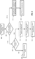
- a UE such as UE 12 ( FIG. 1 ) may perform an aspect of a method 200 of compressed mode operation for wireless communications. While, for purposes of simplicity of explanation, the method is shown and described as a series of acts, it is to be understood and appreciated that the method (and further methods related thereto) is/are not limited by the order of acts, as some acts may, in accordance with one or more aspects, occur in different orders and/or concurrently with other acts from that shown and described herein. For example, it is to be appreciated that a method could alternatively be represented as a series of interrelated states or events, such as in a state diagram. Moreover, not all illustrated acts may be required to implement a method in accordance with one or more features described herein.
- the method 200 may include receiving a downlink dedicated physical channel (DPCH) having a slot-format and a spreading factor during a first compression interval, wherein the downlink DPCH does not include a compressed-mode transmission gap during the first compression interval.
- DPCH downlink dedicated physical channel
- the receiver 36 may receive the downlink DPCH having a slot-format and a spreading factor during a first compression interval.
- the transmission gap component 44 may indicate that the first compression interval does not include a transmission gap.
- the method 200 may include receiving the downlink DPCH having the same slot-format and the same spreading factor during a second compression interval.
- the receiver 36 may receive the downlink DPCH having the same slot-format and the same spreading factor during a second compression interval.
- the method 200 may include determining that the downlink DPCH includes a compressed-mode transmission gap during the second compression interval, wherein a set of slots of the downlink DPCH during the transmission gap are punctured.
- the transmission gap component 44 may determine that the downlink DPCH includes a compressed-mode transmission gap during the second compression interval, wherein a set of slots of the downlink DPCH during the transmission gap are punctured.
- the transmission gap component 44 may determine the set of slots during the second compression interval that will be punctured to provide the transmission gap.
- the receiver 36 may be tuned to another frequency to, for example, perform measurements. And the receiver 36 may not receive the downlink DPCH during the punctured slots.
- the method 200 may include decoding the downlink DPCH for the second compression interval based on a set of remaining slots received during the second compression interval.
- the decoder 48 may decode the downlink DPCH for the second compression interval based on a set of remaining slots received during the second compression interval.
- the slot mapping component 46 may determine the set of remaining slots based on the transmission gap.
- the set of remaining slots may include slots that are not punctured, for example, any slot that is not in the transmission gap.
- the decoder 48 may decode the downlink DPCH based on a subset of the set of remaining slots.
- the decoder 48 may be able to successfully decode the downlink DPCH early (e.g. before the end of the compression interval) based on a first number of remaining slots that are received. If decoding is unsuccessful, the decoder 48 may attempt decoding using additional remaining slots as the remaining slots are received.
- the method 200 may optionally include estimating a downlink SIR based on the downlink DPCH received during the second compression interval.
- the signal estimating component 52 may estimate the downlink SIR based on the downlink DPCH received during the second compression interval.
- the signal estimating component 52 may obtain measurements of different portions of the received signal to estimate the SIR.
- the SIR estimate may be based on a downlink TPC command having a fixed value.
- the last slot of a transmission gap may include a TPC command having a fixed value that may be used to accurately estimate the SIR.
- the method 200 may optionally include comparing the estimated downlink SIR to an adjusted SIR target, wherein the adjusted SIR target is increased based on the determination that the second compression interval includes a compressed mode transmission gap.
- the signal estimating component 52 may compare the estimated downlink SIR to an adjusted SIR target.
- the adjusted SIR target or a parameter defining the adjusted SIR target may be provided by the radio resource control component 32.
- the method 200 may optionally include generating an uplink TPC command based on whether the estimated downlink SIR satisfies the adjusted SIR target.
- the transmitter 34 may generate the uplink TPC command.
- the uplink TPC command may be transmitted on an uplink control channel for use by the network entity for controlling the transmit power of the downlink DPCH.
- the transmitter 34 may generate an UP TPC command to increase the transmit power of the downlink DPCH.
- the transmitter 34 may generate a DOWN TPC command to decrease the transmit power of the downlink DPCH.
- a network entity such as network entity 14 ( FIG. 1 ) may perform an aspect of a method 300 of providing a compressed mode transmission gap in wireless communications. While, for purposes of simplicity of explanation, the method is shown and described as a series of acts, it is to be understood and appreciated that the method (and further methods related thereto) is/are not limited by the order of acts, as some acts may, in accordance with one or more aspects, occur in different orders and/or concurrently with other acts from that shown and described herein. For example, it is to be appreciated that a method could alternatively be represented as a series of interrelated states or events, such as in a state diagram. Moreover, not all illustrated acts may be required to implement a method in accordance with one or more features described herein.
- the method 300 may optionally include determining compressed mode parameters.
- the compressed mode component 60 may determine the compressed mode parameters.
- the compressed mode parameters may be received from the network 18 or the RNC 16.
- the compressed mode parameters may be selected to avoid excessive puncturing of the downlink DPCH.
- the compressed mode parameters may be selected to allow voice packets using known voice codecs to be transmitted with a particular effective coding rate even when a compression interval includes a compressed mode transmission gap.
- the compressed mode parameters may be selected such that a total number of slots in transmission gaps in two consecutive compression intervals is less than or equal to 15.
- the method 300 may include transmitting a downlink DPCH having a slot-format and a spreading factor during a first compression interval, wherein the DPCH does not include a compressed mode transmission gap during the first compression interval.
- the transmitter 72 may transmit the downlink DPCH having a slot-format and a spreading factor during a first compression interval.
- the slot mapping component 66 may determine the slot format.
- the transmission gap component 64 may indicate that the compression interval does not include a transmission gap.
- the method 300 may include determining that the downlink DPCH includes the compressed mode transmission gap during a second compression interval.
- the transmission gap component 64 may determine that the downlink DPCH includes the compressed mode transmission gap during the second compression interval.
- the transmission gap component 64 may determine the location of the transmission gap based on the configured compressed mode parameters.
- the method 300 may include transmitting the downlink DPCH using the same slot-format and the same spreading factor as the first compression interval during every slot of the second compression interval except the slots during the compressed mode transmission gap.
- the transmitter 72 may transmit the downlink DPCH using the same slot-format and the same spreading factor as the first compression interval during every slot of the second compression interval except the slots during the compressed mode transmission gap.
- the downlink DPCH may be transmitted using a 20 ms TTI.
- the transmitting may include puncturing the slots during the transmission gap.
- the transmitter 72 may stop the transmission , use discontinuous transmission, or transmit the downlink DPCH with reduced or zero power during the transmission gap.
- the downlink DPCH transmission may be stopped early if the FET component 68 receives a FET ACK on an uplink DPCH.
- the network entity 14 may conserve radio resources such as OVSF codes.
- the downlink DPCH may be transmitted with a boosted power when the compression interval includes a transmission gap.
- the transmit power used for the 20 ms TTI including the transmission gap may be the same as a transmit power used for a 10 ms TTI.
- the transmit power may be further boosted based on the effective coding rate of the downlink DPCH. For example, if the effective coding rate exceeds a threshold (e.g. 2/3), the transmit power may be boosted.
- a UE such as UE 12 ( FIG. 1 ) may perform an aspect of a method 400 of compressed mode operation for wireless communications. While, for purposes of simplicity of explanation, the method is shown and described as a series of acts, it is to be understood and appreciated that the method (and further methods related thereto) is/are not limited by the order of acts, as some acts may, in accordance with one or more aspects, occur in different orders and/or concurrently with other acts from that shown and described herein. For example, it is to be appreciated that a method could alternatively be represented as a series of interrelated states or events, such as in a state diagram. Moreover, not all illustrated acts may be required to implement a method in accordance with one or more features described herein.
- the method 400 may optionally include transmitting a capability indication that the UE 12 supports compressed mode operation with DCH enhancements.
- the RRC component 32 may transmit the capability indication that the UE 12 supports compressed mode operation with DCH enhancements via the transmitter 34.
- the indication may be the value of a bit, flag, or information element in a UE capability information message.
- the RRC component 32 may determine the capability of the UE 12, for example, based on the presence and configuration of the compressed mode component 40.
- the method 400 may include configuring an uplink DPCH to include a compressed mode transmission gap using a set of gap slots during a compression interval for an uplink transmission.
- the transmission gap component 44 may configure the uplink DPCH to include a compressed mode transmission gap using a set of gap slots during a compression interval for an uplink transmission.
- the transmission gap configuration may be based on a compressed mode configuration received from the network 18 by the RRC component 32 ( FIG. 1 ).
- the compression interval may be a 20 ms interval including a first 10 ms radio frame and a second 10 ms radio frame. Each radio frame may include 15 slots.
- the method 400 may include mapping the uplink transmission to a set of mapped slots in the compression interval, the set of mapped slots excluding the set of gap slots.
- the slot mapping component 46 FIG. 1
- the mapping may include scheduling a first part of the uplink transmission in a first subset of the mapped slots before the set of gap slots and a second part of the uplink transmission in a second subset of the mapped slots after the set of gap slots.
- a first number of the mapped slots may include a TFCI field.
- a slot after the first number of slots may include an ACK/NAK field in place of the TFCI field.
- the method 400 may include transmitting the uplink transmission during the mapped slots but not during the set of gap slots.
- the transmitter 34 ( FIG. 1 ) may transmit the uplink transmission during the mapped slots but not during the set of gap slots.
- the transmitter may transmit data mapped to each mapped slot during the mapped slot.
- the data may include one of the TFCI field or ACK/NAK field.
- the transmitter may be turned off or used for other purposes. Any data scheduled for transmission during the gap slots may be blanked or transmitted with zero power.
- the method 400 may optionally include gating the uplink transmission following transmission of an acknowledgment when there is no transport block for the uplink dedicated physical channel.
- the FET component 50 ( FIG. 1 ) may gate the uplink transmission following transmission of an acknowledgment when there is no transport block for the uplink dedicated physical channel.
- the FET component 50 may determine that an ACK has been transmitted and that there is no data to transmit in the uplink, or that the uplink data has been transmitted. The FET component 50 may then turn off the transmitter 34 for a remaining portion of a TTI.
- a UE such as UE 12 ( FIG. 1 ) may perform an aspect of a method 500 of transmission mapping.
- the method 500 may be performed by the slot mapping component 46.
- the method is shown and described as a series of acts, it is to be understood and appreciated that the method (and further methods related thereto) is/are not limited by the order of acts, as some acts may, in accordance with one or more aspects, occur in different orders and/or concurrently with other acts from that shown and described herein.
- a method could alternatively be represented as a series of interrelated states or events, such as in a state diagram.
- not all illustrated acts may be required to implement a method in accordance with one or more features described herein.
- the method 500 may include determining that a transmission gap is required during a 20 ms compression interval.
- the slot mapping component 46 may receive a transmission gap configuration from the transmission gap component 44 indicating which slots are to be used for the transmission gap.
- the method 500 may include determining whether the UE 12 is operating in a 10 ms TTI mode or a 20 ms TTI mode. The determination may be made at the physical layer based on the uplink power headroom. If the UE 12 is operating in the 10 ms TTI mode, the uplink transmission may include only bits for the for a first radio frame of the 20 ms compression interval. At block 506, the method 500 may include determining whether the transmission gap overlaps the first radio frame. If the transmission gap does not overlap the first radio frame, the method 500 may include, at block 508, mapping the uplink transmission to the first frame. The uplink transmission may be mapped completely to slots before the transmission gap.
- the method 500 may optionally include mapping the uplink transmission to slots of the first frame before the transmission gap. For example, if the transmission gap begins at slot N first and continues to slot N last , a first part of the transmission may be mapped to slots 0 to N first . In block 512, the method 500 may optionally include mapping a second part of the transmission to slots of the first frame after the transmission gap. If the transmission gap ends before the end of the frame, for example, the second part of the transmission may be mapped to slot N last +1 to slot 14.
- the method 500 may include mapping a third part of the transmission to slots of the second frame.
- the third part may be mapped from slot 0 of the second frame (or slot N last +1 if the transmission gap overlaps the second frame) to slot (TGL) of the second frame.
- the third part may be mapped to a number of slots equal to the transmission gap length in the second frame.
- the method 500 may include using higher layer scheduling to reduce the size of the transmission.
- the size of the transmission may be limited such that the transmission can be decoded with puncturing of a number of slots equal to the TGL.
- Spreading factor reduction with a different slot format may also be used to map the transmission to a smaller number of slots.
- the method 500 may include mapping TFCI bits to slots excluding the transmission gap.
- the blocks 510, 512, and 514 used to map a data transmission to slots excluding the transmission gap may be used to map the TFCI bits to slots excluding the transmission gap.
- FIG. 6 illustrates an example of a frame structure 600 having a transmission gap.
- the frame structure 600 may be a frame structure for a 20 ms compression interval 602 in a 20 ms TTI mode.
- the compression interval 602 may include a first radio frame 604 and a second radio frame 606.
- the transmission gap 608 may be 7 slots from slot 5 to slot 11, as illustrated, or a smaller number of slots in a frame.
- a transmission gap may span two frames, using up to 7 slots in each frame.
- both the downlink DPCH and the uplink DPCH may not be transmitted over the air, so any bits assigned to the slots during the transmission gap 608 may be lost.
- the DL DPCH may be scheduled for transmission over the entire 20 ms compression interval.
- the dedicated physical control channel which may include TFCI bits and ACK/NAK bits may be mapped to exclude slots in the transmission gap.
- the TFCI field may be included in the first 10 slots excluding the transmission gap.
- the TFCI field is transmitted in a first subset of mapped slots (0-4 of the first frame) and a second subset of mapped slots (12-14 of the first frame 604 and slots 0 and 1 of the second frame 606).
- FET may be implemented in the frame structure 600.
- the field may be used for the ACK/NAK indication.
- the network entity 14 FIG. 1 ) may stop transmission of the DL DPCH. Accordingly, for example, frames 12-14 may not be transmitted.
- FIG. 7 illustrates another example of a frame structure 700 having a transmission gap 708.
- the frame structure 700 may be a frame structure for a 20 ms compression interval 702 in a 10 ms TTI mode. Accordingly, the frame structure 700 may be similar to the frame structure 600 except that the UL DPCH may be scheduled for transmission in 1 radio frame or 15 slots rather than across the entire 20 ms compression interval.
- the transmission gap 708 in slots 5-11, for example, of the first frame 704
- no uplink transmission may be mapped to the slots in the transmission gap 708. Instead, a first part of the transmission may be mapped to slots 1-4 of the first frame, and a second part of the transmission may be mapped to slots after the transmission gap in the first frame 704 and slots in the second frame 706.
- the uplink transmission may use a total of N + 15, slots where N is the TGL (e.g. 7).
- N is the TGL (e.g. 7).
- the uplink transmission may be gated after the uplink transmission has been completed. Accordingly, because no TPC commands are transmitted, the inner loop power control of the DL DPCH may be frozen for the remainder of the compression interval 702 (e.g. slots 7-14) in the second frame 706. For example, slots 7-14 may be transmitted with the same power as slot 6.
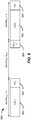
- FIG. 8 illustrates a third example of a frame structure 800 having a transmission gap 808.
- the frame structure 800 may be similar to the frame structure 700. Additionally, the frame structure 800 may provide for FET.
- the UL DPCH may not have any data and only transmit the DPCCH.
- the UL DPCCH may include a TFCI field in the first 10 slots of the uplink transmission excluding the transmission gap 808. After the first 10 slots, the UL DPCCH may include an ACK/NAK field instead of the TFCI field.
- the decoder 48 or FET component 50
- the UE 12 may gate the uplink transmission after slot 3. For example, the UE may stop the UL DPCH transmission.
- the network entity 14 may also receive the ACK and stop the DL DPCH transmission early.
- FIG. 9 illustrates a slot format 900, which may be used for DL DPCH in compressed mode.
- a transmission gap may be configured in slots N first to N last .
- the slot format 900 may be a pilot-free slot format.
- Each transmitted slot may include a data portion 902 and a TPC command 904.
- the TPC commands 904 may be used for SIR estimates in addition to inner loop power control. Accordingly, a pilot signal within each slot may not be necessary.
- the network entity 14 may not transmit the data portion 902.
- the slot format 900 may also include a special TPC command 906 within the transmission gap.
- the special TPC command 906 may have a fixed value.
- the special TPC command 906 may have a fixed value of 0.
- the UE 12 may estimate a downlink SIR or SINR based on the special TPC command 906.
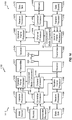
- FIG. 10 is a block diagram illustrating an example of a hardware implementation for an apparatus 1000 employing a processing system 1014 and including a compressed mode component 40.
- the processing system 1014 may be implemented with a bus architecture, represented generally by the bus 1002.
- the bus 1002 may include any number of interconnecting buses and bridges depending on the specific application of the processing system 1014 and the overall design constraints.
- the bus 1002 links together various circuits including the compressed mode component 40, one or more processors, represented generally by the processor 1004, and computer-readable media, represented generally by the computer-readable medium 1006.
- the bus 1002 may also link various other circuits such as timing sources, peripherals, voltage regulators, and power management circuits, which are well known in the art, and therefore, will not be described any further.
- a bus interface 1008 provides an interface between the bus 1002 and a transceiver 1010.
- the transceiver 1010 provides a means for communicating with various other apparatus over a transmission medium.
- a user interface 1012 e.g., keypad, display, speaker, microphone, joystick
- the processor 1004 is responsible for managing the bus 1002 and general processing, including the execution of software stored on the computer-readable medium 1006.
- the software when executed by the processor 1004, causes the processing system 1014 to perform the various functions described infra for any particular apparatus.
- the computer-readable medium 1006 may also be used for storing data that is manipulated by the processor 1004 when executing software.
- the compressed mode component 40 may be implemented by the processor 1004, the computer-readable medium 1006, or a combination thereof.
- the computer-readable medium 1006 may store instruction executable by the processor 1004 for providing compressed mode gaps as described herein.
- a UMTS network includes three interacting domains: a Core Network (CN) 1104, a UMTS Terrestrial Radio Access Network (UTRAN) 1102, and User Equipment (UE) 1110.
- the UE 1110 may be an example of the UE 12 ( FIG. 1 ) and include a compressed mode component 40 for providing compressed mode transmission gaps.
- the UTRAN 1102 provides various wireless services including telephony, video, data, messaging, broadcasts, and/or other services.
- the UTRAN 1102 may include a plurality of Radio Network Subsystems (RNSs) such as an RNS 1107, each controlled by a respective Radio Network Controller (RNC) such as an RNC 1106. Further, the RNS 1107 may include one or more Node Bs 1108, which may each be an example of the Network entity 14 ( FIG. 1 ) and include a compressed mode component 60.
- the UTRAN 1102 may include any number of RNCs 1106 and RNSs 1107 in addition to the RNCs 1106 and RNSs 1107 illustrated herein.
- the RNC 1106 is an apparatus responsible for, among other things, assigning, reconfiguring and releasing radio resources within the RNS 1107.
- the RNC 1106 may be interconnected to other RNCs (not shown) in the UTRAN 1102 through various types of interfaces such as a direct physical connection, a virtual network, or the like, using any suitable transport network.
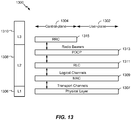
- Communication between a UE 1110 and a Node B 1108 may be considered as including a physical (PHY) layer and a medium access control (MAC) layer. Further, communication between a UE 1110 and an RNC 1106 by way of a respective Node B 1108 may be considered as including a RRC layer.
- the PHY layer may be considered layer 1; the MAC layer may be considered layer 2; and the RRC layer may be considered layer 3.
- the compressed mode component 40 and the compressed mode component 60 may communicate at the PHY layer.
- the geographic region covered by the RNS 1107 may be divided into a number of cells, with a radio transceiver apparatus serving each cell.
- a radio transceiver apparatus is commonly referred to as a Node B in UMTS applications, but may also be referred to by those skilled in the art as a base station (BS), a base transceiver station (BTS), a radio base station, a radio transceiver, a transceiver function, a basic service set (BSS), an extended service set (ESS), an access point (AP), or some other suitable terminology.
- BS basic service set
- ESS extended service set
- AP access point
- three Node Bs 1108 are shown in each RNS 1107; however, the RNSs 1107 may include any number of wireless Node Bs.
- the Node Bs 1108 provide wireless access points to a CN 1104 for any number of mobile apparatuses.
- a mobile apparatus include a cellular phone, a smart phone, a session initiation protocol (SIP) phone, a laptop, a notebook, a netbook, a smartbook, a personal digital assistant (PDA), a satellite radio, a global positioning system (GPS) device, a multimedia device, a video device, a digital audio player (e.g., MP3 player), a camera, a game console, or any other similar functioning device.
- SIP session initiation protocol
- PDA personal digital assistant
- GPS global positioning system
- multimedia device e.g., a digital audio player (e.g., MP3 player), a camera, a game console, or any other similar functioning device.
- MP3 player digital audio player
- the mobile apparatus is commonly referred to as a UE in UMTS applications, but may also be referred to by those skilled in the art as a mobile station, a subscriber station, a mobile unit, a subscriber unit, a wireless unit, a remote unit, a mobile device, a wireless device, a wireless communications device, a remote device, a mobile subscriber station, an access terminal, a mobile terminal, a wireless terminal, a remote terminal, a handset, a terminal, a user agent, a mobile client, a client, or some other suitable terminology.
- the UE 1110 may further include a universal subscriber identity module (USIM) 1111, which contains a user's subscription information to a network.
- USIM universal subscriber identity module
- one UE 1110 is shown in communication with a number of the Node Bs 1108.
- the DL also called the forward link, refers to the communication link from a Node B 1108 to a UE 1110
- the UL also called the reverse link, refers to the communication link from a UE 1110 to a Node B 1108.
- the CN 1104 interfaces with one or more access networks, such as the UTRAN 1102. As shown, the CN 1104 is a GSM core network. However, as those skilled in the art will recognize, the various concepts presented throughout this disclosure may be implemented in a RAN, or other suitable access network, to provide UEs with access to types of CNs other than GSM networks.
- the CN 1104 includes a circuit-switched (CS) domain and a packet-switched (PS) domain.
- Some of the circuit-switched elements are a Mobile services Switching Centre (MSC), a Visitor location register (VLR) and a Gateway MSC.
- Packet-switched elements include a Serving GPRS Support Node (SGSN) and a Gateway GPRS Support Node (GGSN).
- Some network elements, like EIR, HLR, VLR and AuC may be shared by both of the circuit-switched and packet-switched domains.
- the CN 1104 supports circuit-switched services with a MSC 1112 and a GMSC 1114.
- the GMSC 1114 may be referred to as a media gateway (MGW).
- MGW media gateway
- One or more RNCs, such as the RNC 1106, may be connected to the MSC 1112.
- the MSC 1112 is an apparatus that controls call setup, call routing, and UE mobility functions.
- the MSC 1112 also includes a VLR that contains subscriber-related information for the duration that a UE is in the coverage area of the MSC 1112.
- the GMSC 1114 provides a gateway through the MSC 1112 for the UE to access a circuit-switched network 1116.
- the GMSC 1114 includes a home location register (HLR) 1115 containing subscriber data, such as the data reflecting the details of the services to which a particular user has subscribed.
- HLR home location register
- the HLR is also associated with an authentication center (AuC) that contains subscriber-specific authentication data.
- AuC authentication center
- the GMSC 1114 queries the HLR 1115 to determine the UE's location and forwards the call to the particular MSC serving that location.
- the CN 1104 also supports packet-data services with a serving GPRS support node (SGSN) 1118 and a gateway GPRS support node (GGSN) 1120.
- GPRS which stands for General Packet Radio Service, is designed to provide packet-data services at speeds higher than those available with standard circuit-switched data services.
- the GGSN 1120 provides a connection for the UTRAN 1102 to a packet-based network 1122.
- the packet-based network 1122 may be the Internet, a private data network, or some other suitable packet-based network.
- the primary function of the GGSN 1120 is to provide the UEs 1110 with packet-based network connectivity. Data packets may be transferred between the GGSN 1120 and the UEs 1110 through the SGSN 1118, which performs primarily the same functions in the packet-based domain as the MSC 1112 performs in the circuit-switched domain.
- An air interface for UMTS may utilize a spread spectrum Direct-Sequence Code Division Multiple Access (DS-CDMA) system.
- the spread spectrum DS-CDMA spreads user data through multiplication by a sequence of pseudorandom bits called chips.
- the "wideband" W-CDMA air interface for UMTS is based on such direct sequence spread spectrum technology and additionally calls for a frequency division duplexing (FDD).
- FDD uses a different carrier frequency for the UL and DL between a Node B 1108 and a UE 1110.
- Another air interface for UMTS that utilizes DS-CDMA, and uses time division duplexing (TDD), is the TD-SCDMA air interface.
- TD-SCDMA time division duplexing
- HSPA air interface includes a series of enhancements to the 3G/W-CDMA air interface, facilitating greater throughput and reduced latency.
- HSPA utilizes hybrid automatic repeat request (HARQ), shared channel transmission, and adaptive modulation and coding.
- HARQ hybrid automatic repeat request
- the standards that define HSPA include HSDPA (high speed downlink packet access) and HSUPA (high speed uplink packet access, also referred to as enhanced uplink, or EUL).
- HSDPA utilizes as its transport channel the high-speed downlink shared channel (HS-DSCH).
- the HS-DSCH is implemented by three physical channels: the high-speed physical downlink shared channel (HS-PDSCH), the high-speed shared control channel (HS-SCCH), and the high-speed dedicated physical control channel (HS-DPCCH).
- HS-PDSCH high-speed physical downlink shared channel
- HS-SCCH high-speed shared control channel
- HS-DPCCH high-speed dedicated physical control channel
- the HS-DPCCH carries the HARQ ACK/NACK signaling on the uplink to indicate whether a corresponding packet transmission was decoded successfully. That is, with respect to the downlink, the UE 1110 provides feedback to the node B 1108 over the HS-DPCCH to indicate whether it correctly decoded a packet on the downlink.
- HS-DPCCH further includes feedback signaling from the UE 1110 to assist the node B 1108 in taking the right decision in terms of modulation and coding scheme and precoding weight selection, this feedback signaling including the CQI and PCI.
- HSPA Evolved or HSPA+ is an evolution of the HSPA standard that includes MIMO and 64-QAM, enabling increased throughput and higher performance. That is, in an aspect of the disclosure, the node B 1108 and/or the UE 1110 may have multiple antennas supporting MIMO technology. The use of MIMO technology enables the node B 1108 to exploit the spatial domain to support spatial multiplexing, beamforming, and transmit diversity.
- MIMO Multiple Input Multiple Output
- MIMO systems generally enhance data transmission performance, enabling diversity gains to reduce multipath fading and increase transmission quality, and spatial multiplexing gains to increase data throughput.
- Spatial multiplexing may be used to transmit different streams of data simultaneously on the same frequency.
- the data steams may be transmitted to a single UE 1110 to increase the data rate or to multiple UEs 1110 to increase the overall system capacity. This is achieved by spatially precoding each data stream and then transmitting each spatially precoded stream through a different transmit antenna on the downlink.
- the spatially precoded data streams arrive at the UE(s) 1110 with different spatial signatures, which enables each of the UE(s) 1110 to recover the one or more the data streams destined for that UE 1110.
- each UE 1110 may transmit one or more spatially precoded data streams, which enables the node B 1108 to identify the source of each spatially precoded data stream.
- Spatial multiplexing may be used when channel conditions are good.
- beamforming may be used to focus the transmission energy in one or more directions, or to improve transmission based on characteristics of the channel. This may be achieved by spatially precoding a data stream for transmission through multiple antennas. To achieve good coverage at the edges of the cell, a single stream beamforming transmission may be used in combination with transmit diversity.
- n transport blocks may be transmitted simultaneously over the same carrier utilizing the same channelization code. Note that the different transport blocks sent over the n transmit antennas may have the same or different modulation and coding schemes from one another.
- Single Input Multiple Output generally refers to a system utilizing a single transmit antenna (a single input to the channel) and multiple receive antennas (multiple outputs from the channel).
- a single transport block is sent over the respective carrier.
- the access network 1200 may include a number of UEs 1230, 1232, 1234, 1236, 1238, 1240, each of which may be an example of the UE 12 in FIG. 1 and include a compressed mode component 40.
- the multiple access wireless communication system includes multiple cellular regions (cells), including cells 1202, 1204, and 1206, each of which may include one or more sectors and be provided by a respective Node B 1242, 1244, 1246, each of which may be an example of the network entity 14 ( FIG. 1 ) and include a compressed mode component 60.
- the multiple sectors can be formed by groups of antennas with each antenna responsible for communication with UEs in a portion of the cell.
- antenna groups 1212, 1214, and 1216 may each correspond to a different sector.
- antenna groups 1218, 1220, and 1222 each correspond to a different sector.
- antenna groups 1224, 1226, and 1228 each correspond to a different sector.
- the cells 1202, 1204 and 1206 may include several wireless communication devices, e.g., UEs, which may be in communication with one or more sectors of each cell 1202, 1204 or 1206.
- UEs 1230 and 1232 may be in communication with Node B 1242
- UEs 1234 and 1236 may be in communication with Node B 1244
- UEs 1238 and 1240 can be in communication with Node B 1246.
- each Node B 1242, 1244, 1246 is configured to provide an access point to a CN 1104 (see FIG. 11 ) for all the UEs 1230, 1232, 1234, 1236, 1238, 1240 in the respective cells 1202, 1204, and 1206.
- a serving cell change (SCC) or handover may occur in which communication with the UE 1234 transitions from the cell 1204, which may be referred to as the source cell, to cell 1206, which may be referred to as the target cell.
- Management of the handover procedure may take place at the UE 1234, at the Node Bs corresponding to the respective cells, at a radio network controller 1106 (see FIG. 11 ), or at another suitable node in the wireless network.
- the UE 1234 may monitor various parameters of the source cell 1204 as well as various parameters of neighboring cells such as cells 1206 and 1202.
- the UE 1234 may maintain communication with one or more of the neighboring cells. During this time, the UE 1234 may maintain an Active Set, that is, a list of cells that the UE 1234 is simultaneously connected to (i.e., the UTRA cells that are currently assigning a downlink dedicated physical channel DPCH or fractional downlink dedicated physical channel F-DPCH to the UE 1234 may constitute the Active Set). Each of the cells in the Active Set may include a compressed mode component 60 for providing transmission gaps in the DPCH with the UE 1234.
- an Active Set that is, a list of cells that the UE 1234 is simultaneously connected to (i.e., the UTRA cells that are currently assigning a downlink dedicated physical channel DPCH or fractional downlink dedicated physical channel F-DPCH to the UE 1234 may constitute the Active Set).
- Each of the cells in the Active Set may include a compressed mode component 60 for providing transmission gaps in the DPCH with the UE 1234.
- the modulation and multiple access scheme employed by the access network 1200 may vary depending on the particular telecommunications standard being deployed.
- the standard may include Evolution-Data Optimized (EV-DO) or Ultra Mobile Broadband (UMB).
- EV-DO and UMB are air interface standards promulgated by the 3rd Generation Partnership Project 2 (3GPP2) as part of the CDMA2000 family of standards and employs CDMA to provide broadband Internet access to mobile stations.
- 3GPP2 3rd Generation Partnership Project 2
- the standard may alternately be Universal Terrestrial Radio Access (UTRA) employing Wideband-CDMA (W-CDMA) and other variants of CDMA, such as TD-SCDMA; Global System for Mobile Communications (GSM) employing TDMA; and Evolved UTRA (E-UTRA), Ultra Mobile Broadband (UMB), IEEE 802.11 (Wi-Fi), IEEE 802.16 (WiMAX), IEEE 802.20, and Flash-OFDM employing OFDMA.
- UTRA, E-UTRA, UMTS, LTE, LTE Advanced, and GSM are described in documents from the 3GPP organization.
- CDMA2000 and UMB are described in documents from the 3GPP2 organization.
- the actual wireless communication standard and the multiple access technology employed will depend on the specific application and the overall design constraints imposed on the system.
- the radio protocol architecture may take on various forms depending on the particular application.
- An example for an W-CDMA system will now be presented with reference to FIG. 13 .
- an example radio protocol architecture 1300 relates to the user plane 1302 and the control plane 1304 of a user equipment (UE) or node B/base station.
- architecture 1300 may be included in a UE such as the UE 12 ( FIG. 1 ).
- the radio protocol architecture 1300 for the UE and node B is shown with three layers: Layer 1 1306, Layer 2 1308, and Layer 3 1310.
- Layer 1 1306 is the lowest lower and implements various physical layer signal processing functions.
- Layer 1 1306 includes the physical layer 1307.
- Layer 2 (L2 layer) 1308 is above the physical layer 1307 and is responsible for the link between the UE and node B over the physical layer 1307.
- Layer 3 (L3 layer) 1310 includes a radio resource control (RRC) sublayer 1315.
- the RRC sublayer 1315 handles the control plane signaling of Layer 3 between the UE and the UTRAN.
- the compressed mode component 40 may be implemented at the physical layer 1307.
- the compressed mode parameters may be configured by Layer 3 RRC signaling but the other communications discussed herein may occur between the UE 12 and network entity 14 at the physical layer 1307.
- various aspects of the compressed mode operation may be transparent to higher layers. For example, as discussed above, uplink transmissions may be mapped to slots of two radio frames to exclude the transmission gap. As long as the transmission gaps are available for measurements as configured by the RRC layer, the higher layer may not affected by the physical channel slots mapped.
- the FET ACK/NACK procedure discussed herein does not change the order of transmissions and may be transparent to higher layers.
- the L2 layer 1308 includes a media access control (MAC) sublayer 1309, a radio link control (RLC) sublayer 1311, and a packet data convergence protocol (PDCP) 1313 sublayer, which are terminated at the node B on the network side.
- MAC media access control
- RLC radio link control
- PDCP packet data convergence protocol
- the UE may have several upper layers above the L2 layer 1308 including a network layer (e.g., IP layer) that is terminated at a PDN gateway on the network side, and an application layer that is terminated at the other end of the connection (e.g., far end UE, server, etc.).
- IP layer e.g., IP layer
- the PDCP sublayer 1313 provides multiplexing between different radio bearers and logical channels.
- the PDCP sublayer 1313 also provides header compression for upper layer data packets to reduce radio transmission overhead, security by ciphering the data packets, and handover support for UEs between node Bs.
- the RLC sublayer 1311 provides segmentation and reassembly of upper layer data packets, retransmission of lost data packets, and reordering of data packets to compensate for out-of-order reception due to hybrid automatic repeat request (HARQ).
- HARQ hybrid automatic repeat request
- the MAC sublayer 1309 provides multiplexing between logical and transport channels.
- the MAC sublayer 1309 is also responsible for allocating the various radio resources (e.g., resource blocks) in one cell among the UEs.
- the MAC sublayer 1309 is also responsible for HARQ operations.
- FIG. 14 is a block diagram of a Node B 1410 in communication with a UE 1450, where the Node B 1410 may be the Node B 1308 in FIG. 12 , and the UE 1450 may be the UE 1210 in FIG. 12 .
- a transmit processor 1420 may receive data from a data source 1412 and control signals from a controller/processor 1440 and/or compressed mode component 60.
- the transmit processor 1420 provides various signal processing functions for the data and control signals, as well as reference signals (e.g., pilot signals).
- the transmit processor 1420 may provide cyclic redundancy check (CRC) codes for error detection, coding and interleaving to facilitate forward error correction (FEC), mapping to signal constellations based on various modulation schemes (e.g., binary phase-shift keying (BPSK), quadrature phase-shift keying (QPSK), M-phase-shift keying (M-PSK), M-quadrature amplitude modulation (M-QAM), and the like), spreading with orthogonal variable spreading factors (OVSF), and multiplying with scrambling codes to produce a series of symbols.
- BPSK binary phase-shift keying
- QPSK quadrature phase-shift keying
- M-PSK M-phase-shift keying
- M-QAM M-quadrature amplitude modulation
- OVSF orthogonal variable spreading factors
- the channel estimates may be derived from a reference signal transmitted by the UE 1450 or from feedback from the UE 1450.
- the symbols generated by the transmit processor 1420 are provided to a transmit frame processor 1430 to create a frame structure.
- the transmit frame processor 1430 creates this frame structure by multiplexing the symbols with information from the controller/processor 1440, resulting in a series of frames.
- the transmit frame processor 1430 may receive slot mapping information from the compressed mode component 60
- the frames are then provided to a transmitter 1432, which provides various signal conditioning functions including amplifying, filtering, and modulating the frames onto a carrier for downlink transmission over the wireless medium through antenna 1434.
- the antenna 1434 may include one or more antennas, for example, including beam steering bidirectional adaptive antenna arrays or other similar beam technologies.
- a receiver 1454 receives the downlink transmission through an antenna 1452 and processes the transmission to recover the information modulated onto the carrier.
- the information recovered by the receiver 1454 is provided to a receive frame processor 1460, which parses each frame, and provides information from the frames to a channel processor 1494 and the data, control, and reference signals to a receive processor 1470.
- the receive processor 1470 then performs the inverse of the processing performed by the transmit processor 1420 in the Node B 1410. More specifically, the receive processor 1470 descrambles and despreads the symbols, and then determines the most likely signal constellation points transmitted by the Node B 1410 based on the modulation scheme. These soft decisions may be based on channel estimates computed by the channel processor 1494.
- the soft decisions are then decoded and deinterleaved to recover the data, control, and reference signals.
- the CRC codes are then checked to determine whether the frames were successfully decoded.
- the data carried by the successfully decoded frames will then be provided to a data sink 1472, which represents applications running in the UE 1450 and/or various user interfaces (e.g., display).
- Control signals carried by successfully decoded frames will be provided to a controller/processor 1490.
- the controller/processor 1490 may also use an acknowledgement (ACK) and/or negative acknowledgement (NACK) protocol to support retransmission requests for those frames.
- the compressed mode component 40 may control channel processor 1494 to perform multiple early decoding attempts until a transmission is successfully decoded.
- a transmit processor 1480 receives data from a data source 1478 and control signals from the controller/processor 1490 and provides various signal processing functions including CRC codes, coding and interleaving to facilitate FEC, mapping to signal constellations, spreading with OVSFs, and scrambling to produce a series of symbols.
- Channel estimates may be used to select the appropriate coding, modulation, spreading, and/or scrambling schemes.
- the symbols produced by the transmit processor 1480 will be provided to a transmit frame processor 1482 to create a frame structure.
- the transmit frame processor 1482 creates this frame structure by multiplexing the symbols with information from the controller/processor 1490, resulting in a series of frames.
- the compressed mode component may provide slot mapping information to the transmit frame processor 1482 for creating the frame structure.
- the frames are then provided to a transmitter 1456, which provides various signal conditioning functions including amplification, filtering, and modulating the frames onto a carrier for uplink transmission over the wireless medium through the antenna 1452.
- the uplink transmission is processed at the Node B 1410 in a manner similar to that described in connection with the receiver function at the UE 1450.
- a receiver 1435 receives the uplink transmission through the antenna 1434 and processes the transmission to recover the information modulated onto the carrier.
- the information recovered by the receiver 1435 is provided to a receive frame processor 1436, which parses each frame, and provides information from the frames to the channel processor 1444 and the data, control, and reference signals to a receive processor 1438.
- the receive processor 1438 performs the inverse of the processing performed by the transmit processor 1480 in the UE 1450.
- the data and control signals carried by the successfully decoded frames may then be provided to a data sink 1439 and the controller/processor, respectively. If some of the frames were unsuccessfully decoded by the receive processor, the controller/processor 1440 may also use an acknowledgement (ACK) and/or negative acknowledgement (NACK) protocol to support retransmission requests for those frames.
- ACK acknowledgement
- NACK negative acknowledgement
- the controller/processors 1440 and 1490 may be used to direct the operation at the Node B 1410 and the UE 1450, respectively.
- the controller/processors 1440 and 1490 may provide various functions including timing, peripheral interfaces, voltage regulation, power management, and other control functions.
- the computer readable media of memories 1442 and 1492 may store data and software for the Node B 1410 and the UE 1450, respectively.
- a scheduler/processor 1446 at the Node B 1410 may be used to allocate resources to the UEs and schedule downlink and/or uplink transmissions for the UEs.
- LTE Long Term Evolution
- LTE-A LTE-Advanced
- EV-DO Evolution-Data Optimized
- UMB Ultra Mobile Broadband
- IEEE 802.11 Wi-Fi
- IEEE 802.16 WiMAX
- IEEE 802.20 Ultra-Wideband
- Bluetooth and/or other suitable systems.
- the actual telecommunication standard, network architecture, and/or communication standard employed will depend on the specific application and the overall design constraints imposed on the system.
- processors include microprocessors, microcontrollers, digital signal processors (DSPs), field programmable gate arrays (FPGAs), programmable logic devices (PLDs), state machines, gated logic, discrete hardware circuits, and other suitable hardware configured to perform the various functionality described throughout this disclosure.
- DSPs digital signal processors
- FPGAs field programmable gate arrays
- PLDs programmable logic devices
- state machines gated logic, discrete hardware circuits, and other suitable hardware configured to perform the various functionality described throughout this disclosure.
- One or more processors in the processing system may execute software.
- Software shall be construed broadly to mean instructions, instruction sets, code, code segments, program code, programs, subprograms, software modules, applications, software applications, software packages, routines, subroutines, objects, executables, threads of execution, procedures, functions, etc., whether referred to as software, firmware, middleware, microcode, hardware description language, or otherwise.
- the software may reside on a computer-readable medium.
- the computer-readable medium may be a non-transitory computer-readable medium.
- a non-transitory computer-readable medium includes, by way of example, a magnetic storage device (e.g., hard disk, floppy disk, magnetic strip), an optical disk (e.g., compact disk (CD), digital versatile disk (DVD)), a smart card, a flash memory device (e.g., card, stick, key drive), random access memory (RAM), read only memory (ROM), programmable ROM (PROM), erasable PROM (EPROM), electrically erasable PROM (EEPROM), a register, a removable disk, and any other suitable medium for storing software and/or instructions that may be accessed and read by a computer.
- a magnetic storage device e.g., hard disk, floppy disk, magnetic strip
- an optical disk e.g., compact disk (CD), digital versatile disk (DVD)
- a smart card e.g., a flash memory device (e.g., card, stick, key drive), random access memory (RAM), read only memory (ROM), programmable ROM
- the computer-readable medium may also include, by way of example, a carrier wave, a transmission line, and any other suitable medium for transmitting software and/or instructions that may be accessed and read by a computer.
- the computer-readable medium may be resident in the processing system, external to the processing system, or distributed across multiple entities including the processing system.
- the computer-readable medium may be embodied in a computer-program product.
- a computer-program product may include a computer-readable medium in packaging materials.
- At least one of: a, b, or c is intended to cover: at least one a; at least one b; at least one c; at least one a and at least one b; at least one a and at least one c; at least one b and at least one c; and at least one a, at least one b and at least one c.
Description
- Aspects of the present disclosure relate generally to wireless communication systems, and more particularly, to physical layer configuration of wireless communications.
- Wireless communication networks are widely deployed to provide various communication services such as telephony, video, data, messaging, broadcasts, and so on. Such networks, which are usually multiple access networks, support communications for multiple users by sharing the available network resources. One example of such a network is the UMTS Terrestrial Radio Access Network (UTRAN). The UTRAN is the radio access network (RAN) defined as a part of the Universal Mobile Telecommunications System (UMTS), a third generation (3G) mobile phone technology supported by the 3rd Generation Partnership Project (3GPP). The UMTS, which is the successor to Global System for Mobile Communications (GSM) technologies, currently supports various air interface standards, such as Wideband-Code Division Multiple Access (W-CDMA), Time Division-Code Division Multiple Access (TD-CDMA), and Time Division-Synchronous Code Division Multiple Access (TD-SCDMA). The UMTS also supports enhanced 3G data communications protocols, such as High Speed Packet Access (HSPA), which provides higher data transfer speeds and capacity to associated UMTS networks.
- As the demand for mobile broadband access continues to increase, research and development continue to advance the UMTS technologies not only to meet the growing demand for mobile broadband access, but to advance and enhance the user experience with mobile communications.
- Release-99 is a standard that defined dedicated channels between a user equipment (UE) and a base station or node B based on orthogonal variable spreading factor (OVSF) codes. Some wireless networks continue to rely on Release-99 channels for various services. For example, a voice call may be carried over a Release-99 dedicated channel (DCH). Release-99 channels allow for a compressed mode (CM) operation to allow a UE to perform measurements on another frequency or another radio access technology (RAT). The Release-99 CM operation may reduce a spreading factor for a DCH. Such spreading factor reduction may present difficulties for network management of a code tree or may result in additional interference when non-orthogonal codes are used. In view of the foregoing, it may be understood that alternative methods of compressed mode operation are desirable.
-
WO 2006/006895 A1 describes a method and apparatus for adjusting a transmit power control process in a mobile radio communications system. - The invention is defined by the appended independent claims. Embodiments of the invention are defined by the appended dependent claims.
- The disclosure provides for a compressed mode transmission gap in wireless communications. A user equipment (UE) may receiving a downlink dedicated physical channel (DPCH) having a slot-format and a spreading factor during a first compression interval. The downlink DPCH may not include a compressed-mode transmission gap during the first compression interval. The UE may receive the downlink DPCH having the same slot-format and the same spreading factor during a second compression interval. The UE may determine that the downlink DPCH includes a compressed-mode transmission gap during the second compression interval. A set of slots of the downlink DPCH during the transmission gap may be punctured. The UE may decode the downlink DPCH for the second compression interval based on a set of remaining slots received during the second compression interval. In an aspect, the UE may estimate a SIR based on a TPC command in a last slot of the transmission gap.
- In one aspect, the disclosure provides a method of providing a compressed mode transmission gap in wireless communications. The method may include receiving a downlink dedicated physical channel DPCH having a slot-format and a spreading factor during a first compression interval, wherein the downlink DPCH does not include a compressed-mode transmission gap during the first compression interval. The method may further include receiving the downlink DPCH having the same slot-format and the same spreading factor during a second compression interval. The method may also include determining that the downlink DPCH includes a compressed-mode transmission gap during the second compression interval, wherein a set of slots of the downlink DPCH during the transmission gap are punctured. The method may additionally include decoding the downlink DPCH for the second compression interval based on a set of remaining slots received during the second compression interval.
- In another aspect, the disclosure includes an apparatus for providing a compressed mode transmission gap in wireless communications. The apparatus may include a receiver configured to receive a downlink dedicated physical channel (DPCH) having a slot-format and a spreading factor during a first compression interval, wherein the downlink DPCH does not include a compressed-mode transmission gap during the first compression interval, and receive the downlink DPCH having the same slot-format and the same spreading factor during a second compression interval. The apparatus may further include a transmit gap component configured to determine that the downlink DPCH includes a compressed-mode transmission gap during the second compression interval, wherein a set of slots of the downlink DPCH during the transmission gap are punctured. The apparatus may also include a decoder configured to decode the downlink DPCH for the second compression interval based on a set of remaining slots received during the second compression interval.
- In another aspect, the disclose includes another apparatus for providing a compressed mode transmission gap in wireless communications. The apparatus may include means for receiving a downlink DPCH having a slot-format and a spreading factor during a first compression interval, wherein the downlink DPCH does not include a compressed-mode transmission gap during the first compression interval. The apparatus may further include means for receiving the downlink DPCH having the same slot-format and the same spreading factor during a second compression interval. The apparatus may also include means for determining that the downlink DPCH includes a compressed-mode transmission gap during the second compression interval, wherein a set of slots of the downlink DPCH during the transmission gap are punctured. The apparatus may additionally include means for decoding the downlink DPCH for the second compression interval based on a set of remaining slots received during the second compression interval.
- Another aspect of the disclosure provides a computer-readable medium storing computer executable code. The a computer-readable medium may include code for receiving a downlink DPCH having a slot-format and a spreading factor during a first compression interval, wherein the downlink DPCH does not include a compressed-mode transmission gap during the first compression interval. The computer-readable medium may also include code for receiving the downlink DPCH having the same slot-format and the same spreading factor during a second compression interval. The computer-readable medium may further include code for determining that the downlink DPCH includes a compressed-mode transmission gap during the second compression interval, wherein a set of slots of the downlink DPCH during the transmission gap are punctured. The computer-readable medium may additionally include code for decoding the downlink DPCH for the second compression interval based on a set of remaining slots received during the second compression interval. The computer-readable medium may be a non-transitory computer-readable medium.
- These and other aspects of the invention will become more fully understood upon a review of the detailed description, which follows.
-
-
FIG. 1 is a diagram illustrating an example of a UE in communication with a Node B. -
FIG. 2 is a flow diagram illustrating an example of a method for providing a compressed mode transmission gap in wireless communications. -
FIG. 3 is a flow diagram illustrating an example of another method for providing a compressed mode transmission gap in wireless communications. -
FIG. 4 is a flow diagram illustrating an example of another method for providing a compressed mode transmission gap in wireless communications. -
FIG. 5 is a flow diagram illustrating an example of a method of mapping an uplink transmission to slots of a compression interval. -
FIG. 6 is a diagram illustrating an example frame structure including a transmission gap. -
FIG. 7 is a diagram illustrating another example frame structure including a transmission gap. -
FIG. 8 is a diagram illustrating another frame structure including a transmission gap. -
FIG. 9 is a diagram illustrating a downlink pilot free slot format for compressed mode. -
FIG. 10 is a block diagram illustrating an example of a hardware implementation for an apparatus employing a processing system. -
FIG. 11 is a block diagram conceptually illustrating an example of a telecommunications system. -
FIG. 12 is a conceptual diagram illustrating an example of an access network. -
FIG. 13 is a conceptual diagram illustrating an example of a radio protocol architecture for the user and control plane. - FIG. 15 is a block diagram conceptually illustrating an example of a Node B in communication with a UE in a telecommunications system.
- The detailed description set forth below in connection with the appended drawings is intended as a description of various configurations and is not intended to represent the only configurations in which the concepts described herein may be practiced. The detailed description includes specific details for the purpose of providing a thorough understanding of various concepts. However, it will be apparent to those skilled in the art that these concepts may be practiced without these specific details. In some instances, well known structures and components are shown in block diagram form in order to avoid obscuring such concepts.
- In some wireless networks, Release-99 channels are still used. For example, Release-99 dedicated channels are often used for voice calls due to channel reliability. Generally, a voice call is transmitted as 20 millisecond (ms) voice packets carried over a Release-99 dedicated channel (DCH) having a 20 ms transmit time interval (TTI). Recent enhancements to the Release-99 DCH are designed to conserve resources such as battery life and improve network capacity. Pseudo-flexible rate matching may be used to improve efficiency of physical channel bit allocation by reducing bits for a signaling radio bearer (SRB) sub-flow when no signaling is being transmitted. The transmit power may be increased to compensate for coding rate increases when the SRB is transmitted. The DCH may also be enhanced by creating opportunities to turn off a receiver or transmitter. In the uplink a dedicated physical data channel (DPDCH) may be compressed at the physical layer such that data normally sent over the 20 ms TTI may be sent over a 10 ms TTI, and the transmitter and receiver may be turned off during another 10 ms period. The compression may use a higher peak power, so a UE may switch between a 10 ms TTI mode and 20 ms TTI mode based on transmit power headroom. Transport format combination indicator (TFCI) bits may be transmitted in the uplink to signal the mode and help decode the transmission. In the downlink, frame early detection (FET) may include multiple attempts to decode the downlink DPDCH before the transmission is completed. When early decoding is successful, an acknowledgment (ACK) may be sent on the uplink, and the remaining portion of a TTI may be set to discontinuous transmission (DTX) or discontinuous receive (DRX). The acknowledgement may be transmitted in slots after the TFCI bits have been transmitted.
- In an aspect, according to the present disclosure, compressed mode may be configured using the above enhancements to Release-99 DCH. In the downlink, the DPCH may use the same slot format and spreading factor for every compression interval. A compression interval including a transmission gap may have the same slot format and spreading factor as a compression interval with no transmission gap. Discontinuous transmission (DTX) may be used during the transmission gap. The UE may decode the DPCH based on the remaining slots of the DPCH that are transmitted. Further, according to one slot format, a transmit power control (TPC) command may be transmitted at the end of each slot. A TPC command having a fixed value may be transmitted at the end of the last slot of a transmission gap. A UE may use the TPC command having a fixed value to estimate a SIR. In an aspect, compressed mode for the downlink DPCH may be implemented without other DCH enhancements. For example, the downlink DPCH may always use a 20 ms TTI without FET.
- In the uplink, a transmission may be mapped to slots excluding slots of the compressed mode transmission gap. The transmission may use slots both before and after the compressed mode transmission gap but not the slots for the compressed mode transmission gap. The TFCI bits may mapped to transmitted slots such that the TFCI bits are transmitted without puncturing. An FET ACK/NAK field may take the place of the TFCI bits in a TTI once all of the TFCI bits have been transmitted
- Referring to
FIG. 1 , in an aspect, awireless communication system 10 includes at least oneUE 12 in communication coverage of at least one network entity 14 (e.g., base station or Node B), wherein theUE 12 includes acompressed mode component 40 for providing transmission gaps on a DCH. Thenetwork entity 14 may also include a correspondingcompressed mode component 60 for providing transmission gaps on the DCH. TheUE 12 may communicate withnetwork 18 vianetwork entity 14 and radio network controller (RNC) 16. In some aspects, multipleUEs including UE 12 may be in communication coverage with one or more network entities, includingnetwork entity 14. In an example,UE 12 may transmit and/or receive wireless communications to and/or fromnetwork entity 14. In an aspect, theRNC 16 may control communication between theUE 12 and one ormore network entities 14. For example, theRNC 16 may determine characteristics of the compressed mode to be implemented by theUE 12 and anetwork entity 14. - In some aspects,
UE 12 may also be referred to by those skilled in the art (as well as interchangeably herein) as a mobile station, a subscriber station, a mobile unit, a subscriber unit, a wireless unit, a remote unit, a mobile device, a wireless device, a wireless communications device, a remote device, a mobile subscriber station, an access terminal, a mobile terminal, a wireless terminal, a remote terminal, a handset, a terminal, a user agent, a mobile client, a client, a device for the Internet of Things, or some other suitable terminology. Additionally,network entity 14 may be a macrocell, picocell, femtocell, relay, Node B, mobile Node B, UE (e.g., communicating in peer-to-peer or ad-hoc mode with UE 12), or substantially any type of component that can communicate withUE 12 to provide wireless network access at theUE 12. - In an aspect, the
network entity 14 may be a base station such as a Node B in an UTRA network. Thenetwork entity 14 may communicate directly with thenetwork 18, or may communicate via the radio network controller (RNC) 16. In an aspect, thenetwork entity 14 and/or theRNC 16 may include a peer compressedmode component 60 for communication with theUE 12. In an example,UE 12 may transmit and/or receivewireless communications 20 to and/or fromnetwork entity 14.Such wireless communications 20 may be, for example, a dedicated channel (DCH) between theUE 12 and anetwork entity 14. At the physical layer, the DCH may include a dedicated physical channel (DPCH). The DPCH may include a dedicated physical data channel (DPDCH) and/or a dedicated physical control channel (DPCCH). - According to the present aspects, a wireless device such as the
UE 12 may include amodem component 30, which may be configured to managewireless communications 20. In an aspect, themodem component 30 may be operable to handle compressed mode operation using DCH enhancements. In an aspect, the term "component" as used herein may be one of the parts that make up a system, may be hardware, firmware, and/or software that may be executed by the hardware, and may be divided into other components. In an aspect, themodem component 30 may include a radio resource control (RRC)component 32 that controls higher layer signaling between theUE 12 and theRNC 16, atransmitter 34 for transmitting radio signals, areceiver 36 for receiving radio signals, and acompressed mode component 40 for managing physical layer communications. - The
RRC component 32 may include hardware or means for implementing a RRC protocol. In an aspect, theRRC component 32 may include or be executable by a processor executing firmware or software for implementing a RRC protocol. The RRC protocol may be described in, for example, 3GPP TS 25.331. In particular, theRRC component 32 may receive signaling for a compressed mode operation. For example, theRRC component 32 may receive a message including a DPCH compressed mode info information element (IE). The DPCH compressed mode IE may include, for example, a transmission gap pattern sequence (TGPS), transmission gap measurement purpose (TGMP), a transmission gap starting slot number (TGSN), one or more transmission gap lengths (TGL), a transmission gap distance (TGD), a transmission gap pattern length (TGPL), power offsets, and/or other information from the network defining compressed mode transmission gaps to be implemented by theUE 12. In an aspect, the compressed mode configuration may be restricted to prevent transmission gaps from causing over-puncturing of DL DPCH. For example, the compressed mode configuration may be restricted to allow no more than 15 slots of transmission gaps in a 40 ms period. - The
transmitter 34 may include hardware for transmitting a wireless radio frequency (RF) signal. For example, thetransmitter 34 may include transmit chain components such as an antenna, a transmitter, a digital-to-analog converter, and filters. In some instances, thetransmitter 34 may include a modulator and/or similar device when, for example, such components are not included in a modem. Thetransmitter 34 may be tuned to a frequency used by thenetwork entity 14 or another base station. - The
receiver 36 may include hardware for receiving a wireless RF signal. For example, thereceiver 36 may include receive chain components such as an antenna, analog-to-digital converter, and filters. In some instances, thereceiver 36 may include a demodulator and/or similar device when, for example, such components are not included in a modem. Thereceiver 36 may be independently tuned for receiving signals at a particular frequency or channel. For example, during a transmission gap, thereceiver 36 may be tuned to a different frequency to perform measurements. - The
compressed mode component 40 may include hardware or means for providing compressed mode transmission gaps on a DCH, as described herein. Further, in an aspect, thecompressed mode component 40 may include or be executable by a processor executing firmware or software for providing compressed mode transmission gaps. For example, thecompressed mode component 40 may configure an uplink DPCH, based on signaling received byRRC component 32 to include a compressed mode transmission gap using a set of gap slots during a compression interval for an uplink transmission. Thecompressed mode component 40 may map the uplink transmission to a set of mapped slots in the compression interval, the set of mapped slots excluding the set of gap slots. Thecompressed mode component 40 may control thetransmitter 34 to transmit the uplink transmission during the mapped slots but not during the set of gap slots. In the downlink, thecompressed mode component 40 may receive a downlink DPDCH having a slot format and a spreading factor. The downlink DPDCH may use the same slot format and spreading factor for a compression interval including a transmission gap as the slot format and spreading factor for a compression interval without a transmission gap. According to one slot format, the DPDCH may include no pilot signal and a TPC command may be located at the end of a slot. The compressed mode component may determine that a compression interval of the DPDCH is scheduled to include a compressed mode transmission gap. Thecompressed mode component 40 may estimate a signal to interference ratio (SIR) for the compression interval and compare the SIR to an increased target SIR. Estimating the SIR may be based on the TPC command received in a last slot of the transmission gap having a fixed value. In an aspect, the SIR may include a signal to interference plus noise ratio (SINR) or similar measurement. Thecompressed mode component 40 may further include a rate matching component 42, a transmission gap component 44, aslot mapping component 46, adecoder 48, and asignal estimating component 52. - The rate matching component 42 may include hardware or means for adjusting a number of data bits assigned to each traffic channel or sub-flow for transmission in an uplink frames. Further, in an aspect, the rate matching component 42 may include or be executable by a processor executing firmware or software for adjusting the number of data bits. In an aspect, the rate matching component 42 may receive one or more transport channels. For example, when using the AMR voice codec, the rate matching component 42 may receive three voice transport channels or sub-flows. The voice transport channels may be concatenated and provided with a cyclic redundancy check (CRC). The rate matching component 42 may also receive a signaling radio bearer (SRB) sub-flow, which may not be present for all frames. The rate matching component 42 may adjust a coding rate such that the bits for the encoded transport channels match a transport block size. For example, the coding may be adjusted so that the number of bits for the encoded transport channels is the same size or smaller than a transport block size. The transport block size may vary based on the presence of a transmission gap within a radio frame. For example, when the radio frame includes a transmission gap, the transport block size may be reduced, so the coding rate may be increased. Because the number of bits for transport channels is not fixed, the rate matching component 42 may be said to perform pseudo-flexible rate matching.
- The transmission gap component 44 may include hardware or means for configuring an uplink DPCH to include a compressed mode transmission gap using a set of gap slots during a compression interval for an uplink transmission. Further, in an aspect, the transmission gap component 44 may include or be executable by a processor executing firmware or software for configuring the uplink DPCH. The transmission gap component 44 may receive a CM configuration from higher layers (e.g. RRC component 32). The transmission gap component 44 may determine which slots are to be used for the transmission gap. For example, the transmission gap component 44 may apply a TGPS to a TGSN to determine when transmission gaps start. The transmission gap component 44 may also use a TGL to determine the end of a transmission gap. In an aspect, the CM configuration may be constrained, for example, to allow a maximum of 7 slots per frame to be used for a transmission gap with 14 slots allowed in a 20 ms compression interval. The CM configuration may be further costrained, for example, to allow a maximum of 15 slots in consecutive compression intervals (40 ms) to be used for a transmission gap. Such restrictions on the CM configuration may prevent excessive puncturing of the DPCH such that, for example, voice packets carried on the DPCH may be successfully decoded.
- The
slot mapping component 46 may include hardware or means for mapping a transmission to a set of mapped slots in a compression interval. Further, in an aspect, theslot mapping component 46 may include or be executable by a processor executing firmware or software for mapping a transmission to a set of mapped slots in a compression interval. In the uplink, theslot mapping component 46 may map the transmission to slots such that the mapped slots exclude any slots used for the transmission gap as configured by the transmission gap component 44. The mapping of the transmission may depend on where the transmission gap is located as well as a transmission TTI. In a 10 ms TTI transmission mode, the transmission may use 15 slots. If a transmission gap overlaps the first frame of the compression interval, a first part of the transmission may be mapped to slots before the transmission gap, and a second part of the transmission may be mapped to slots after the transmission gap. The slots after the transmission gap may be in the first frame and/or the second frame. Generally, a transmission with a 10 ms TTI may be mapped to the first 15 slots of the compression interval excluding any transmission gaps. In a 20 ms TTI mode, theslot mapping component 46 may map slots including a TFCI field to slots excluding the transmission gap. For example, the slots including a TFCI field may be mapped to the first 10 slots excluding the transmission gap. In an aspect, the TFCI field width may vary depending on a configured slot format, so the number of slots including a TFCI field may be the number necessary to transmit all of the TFCI bits (TFCI size / TFCI field width). In the 20 ms TTI mode, DPDCH bits may be mapped to slots in the transmission gap, and may not be transmitted. DCCH bits, including the TFCI bits and ACK/NAK bits; however may be mapped to exclude the transmission gap. The transport block may still be decoded based on the TFCI received in the slots that are transmitted. - For the downlink DPCH, a 20 ms TTI may be used when the compression interval includes a transmission gap regardless of the uplink TTI mode. The downlink DPCH transmission may be mapped to all of the slots in a compression interval including a transmission gap. The
slot mapping component 46 may determine a set of punctured slots that occur during the transmission gap. Theslot mapping component 46 may also determine a set of remaining slots that are not punctured. When the compression interval includes no transmission gap, either a 10 ms or 20 ms TTI may be used. The TTI may be the same as the uplink TTI mode. - The
decoder 48 may include include hardware or means for decoding a received signal. Further, in an aspect, thedecoder 48 may include or be executable by a processor executing firmware or software for decoding a received signal. Thedecoder 48 may decode the downlink DPCH. In an aspect, thedecoder 48 may further include a frame early termination (FET)component 50. TheFET component 50 may include hardware or means for determining whether a downlink transmission has been successfully decoded. For example, theFET component 50 may be implemented with decoder hardware. Further, in an aspect, theFET component 50 may include or be executable by a processor executing firmware or software for determining whether a downlink transmission has been successfully decoded. TheFET component 50 may be configured to attempt early decoding of the downlink transmission. In a first aspect, which may be referred to as basic configuration, the downlink transmission may be configured to decode after 10 ms as long as no SRB/DCCH is present, and thereceiver 36 may be turned off for the second frame. If the SRB/DCCH is present, the downlink transmission may be received for the entire 20 ms compression interval. Also, when the downlink DPCH includes a CM transmission gap, the downlink transmission may be mapped to the entire 20 ms compression interval. In a second aspect, which may be referred to as full configuration, the early decoding may begin when all of the TFCI bits are received. For example, the TFCI bits may be received in the first 10 slots. The downlink transmission may be decoded and the CRC may be checked to determine success. TheFET component 50 may use multiple decoding attempts, for example, every 1 ms or 2 ms until decoding is successful. TheFET component 50 may generate an acknowledgement (ACK) or negative acknowledgment (NAK) indicating whether the early decoding has been successful. In compressed mode, the ACK/NAK may use the TFCI field of the uplink DPCH in each slot after the TFCI bits have been transmitted. For example, in a 10 ms TTI mode, the ACK/NAK may begin after the first 15 slots excluding the transmission gap. As another example, in the 20 ms TTI mode, the slots in a transmission gap may be punctured, but the downlink DPCH may still be decoded early based on the remaining slots. Thenetwork entity 14 may stop transmitting the downlink DPCH when an ACK indication has been received. Accordingly, the downlink DPCH is not necessarily transmitted for the entire TTI. In an aspect, the ACK/NACK may be paired such that two ACKs may be transmitted to indicate successful decoding and reduce the chances of a false positive ACK being received. TheUE 12 may also gate the uplink DPCH early when an ACK has been transmitted and there is no transport block on the DPDCH. - The
signal estimating component 52 may include hardware or means for estimating a SIR during a transmission gap. Further, in an aspect, thesignal estimating component 52 may include or be executable by a processor executing firmware or software for estimating a SIR during a transmission gap. In an aspect, a downlink DPCH may use a pilot-free compressed mode slot format wherein each slot has no pilot signal and a TPC command is located at the end of the slot. In a compressed frame, the last slot of the transmission gap may include a TPC command having a fixed value, for example 0. Thereceiver 36 may be able to receive the TPC command without significantly reducing the length of the transmission gap. For example, thereceiver 36 may receive the TPC command after performing a measurement on another frequency during the transmission gap. Thesignal estimating component 52 may estimate a SIR based on the fixed value of the TPC command and the received TPC command. The SIR may be used, for example, for downlink outer loop power control based on a SIR target. In an aspect, the SIR target may be increased for TTIs including a transmission gap because the transmission gap may puncture DPCH bits. For example, the SIR target may be increased by 3 decibels (dB) for TTIs including the transmission gap. The SIR target may also be increased by 3 dB for transmission in the 10 ms TTI mode. In an aspect, thesignal estimating component 52 may prevent the TPC command having a fixed value for being used for inner loop power control at theUE 12. In another aspect, the TPC command in the last slot of the transmission gap may be a valid TPC command. Thesignal estimating component 52 may determine whether to use the TPC for uplink transmit power control based on, for example, a slot number or received SRB/DCCH. - The
compressed mode component 60, at thenetwork entity 14, may be a peer entity of thecompressed mode component 40. Thecompressed mode component 60 may include hardware or means for implementing, for example, a Node B side compressed mode configuration corresponding to the UE side configuration. In other words, thecompressed mode component 60 may be configured to receive an uplink DPCH transmitted by theUE 12 and transmit a downlink DPCH to theUE 12. In an aspect, thenetwork entity 14 may include a rate matching component 62, atransmission gap component 64, aslot mapping component 66, and aFET component 68. - In an aspect, the rate matching component 62 may be similar to the rate matching component 42. The rate matching component 62 may include hardware or means for adjusting a number of data bits assigned to each traffic channel or sub-flow for transmission in one or more downlink frames. The rate matching component 62 may perform pseudo-flexible rate matching on downlink transport channels based, in part, on whether the downlink frames are configured to include a transmission gap. The rate matching component 62 may determine an effective coding rate when a downlink frame or downlink compression interval includes a transmission gap. Further, the rate matching component 62 may adjust the DPCH transmission power based on the presence of a SRB sub-flow carried on a DCCH and/or the effective coding rate. When the SRB is present, the power may be increased by a configurable power offset (PO2'). Further, because DPDCH bits may be punctured and the effective coding rate lowered, as discussed below, the transmit power may also be boosted for compressed mode frames. In an aspect, a power offset may be applied to a field of the DPCH (e.g. dedicated physical data channel (DPDCH) or dedicated physical control channel (DPCCH)) or both fields. For example, the transmit power may be boosted when the effective coding rate exceeds a threshold, for example, 2/3. When in compressed mode without DCCH, the power may be increased by a configurable power offset (PO2cm). For example, the bits in a DPDCH field may be increased by PO2cm. When in compressed mode with DCCH, the power may be increased by a configurable power offset (PO2cm'). For example, the bits in the DPDCH and/or a DPCCH field may be increased by PO2cm'. The power offsets may have a range of -6 decibels (dB) to 6 dB in steps of 0.25 dB. The power offsets may be signaled to the UE at higher layers for use when the DPCH meets the appropriate criteria.
- The
transmission gap component 64 may be similar to the transmission gap component 44 in thecompressed mode component 40. Thetransmission gap component 64 may include hardware or means for configuring a downlink DPCH to include a compressed mode transmission gap using a set of gap slots during a compression interval for an downlink transmission. Further, thetransmission gap component 64 may determine gap slots used in an uplink DPCH transmission. - The
slot mapping component 66 may correspond to theslot mapping component 46. Theslot mapping component 66 may include hardware or means for mapping an uplink transmission to a set of mapped slots in a compression interval. Theslot mapping component 66 may then correctly interpret received DPCH slots transmitted by theUE 12. For example, theslot mapping component 66 may identify TFCI bits received in DPCH slots. In the downlink, theslot mapping component 66 may map the downlink DPCH based on the transmission mode and compressed mode. In a 10 ms TTI mode, theslot mapping component 66 may map the downlink DPCH to the first 15 slots (10 ms) of a compression interval for a normal transmission. In a 20 ms TTI mode, theslot mapping component 66 may map the downlink DPCH to the all 30 slots (20 ms) of a compression interval for a normal transmission. When the compression interval includes a transmission gap, the theslot mapping component 66 may map the downlink DPCH to all 30 slots (20 ms) of the compression interval regardless of the TTI mode. Further, because theslot mapping component 66 maps the downlink DPCH to all of the slots, the slots during the transmission gap may be punctured (e.g. not transmitted or transmitted with reduced or zero power). - On the downlink, in a basic configuration, the downlink transmission may be configured to decode after 10 ms as long as no SRB/DCCH is present. In an aspect, the compressed mode configuration may be constrained such that transmission gaps are only scheduled during the second 10 ms frame. If the SRB/DCCH is present or the compression interval includes a transmission gap, the downlink transmission may be transmitted for the entire 20 ms compression interval. An increased transmission power (e.g. increased by 3 dB) may be used to transmit the downlink transmission. The increased transmission power may allow for decoding of the downlink transmission based on a set of remaining slots outside of the transmission gap.
- The
slot mapping component 66 may use a pilot-free slot format including a data portion and a TPC command at the end of the slot. Theslot mapping component 66 may map a special TPC command having a fixed value to the last slot of a transmission gap for theUE 12 to use for outer loop power control. Table 1, below, lists example slot formats. Slot formats 17A and 18A may be pilot-free slot formats that may be used for compressed mode without spreading factor (SF) reduction.Table 1 Slot Format #i Channel Bit Rate (kbps) Channel Symbol Rate (ksps) SF Bits/Slot DPDCH Bits/Slot DPCCH Bits/Slot Transmitted slots per radio frame NTr N Data2 NTPC NTFCI NPilot 30 15 256 20 2 14 2 0 2 15 A 30 15 256 20 2 14 2 0 2 8-14 B 60 30 128 40 4 28 4 0 4 8-14 60 30 128 40 6 28 2 0 4 15 A 60 30 128 40 6 28 2 0 4 8-14 B 120 60 64 80 12 56 4 0 8 8-14 7 30 15 256 20 18 0 2 0 0 15 7A 30 15 256 20 18 0 2 0 0 8-14 7B 60 30 128 40 36 0 4 0 0 8-14 8 60 30 128 40 38 0 2 0 0 15 8A 60 30 128 40 38 0 2 0 0 8-14 8B 120 60 64 80 76 0 4 0 0 8-14 - The
FET component 68 may correspond to theFET component 50 in thecompressed mode component 40. TheFET component 68 may include hardware or means for determining whether a downlink transmission has been successfully decoded. TheFET component 68 may decode the uplink DPCCH to determine whether theUE 12 has transmitted an ACK. In an aspect, theFET component 68 may require paired ACK signals to determine that the downlink transmission has been successfully received. When theFET component 68 detects an ACK, theFET component 68 may DTX the downlink DPCH. - Referring to
FIG. 2 , in an operational aspect, a UE such as UE 12 (FIG. 1 ) may perform an aspect of amethod 200 of compressed mode operation for wireless communications. While, for purposes of simplicity of explanation, the method is shown and described as a series of acts, it is to be understood and appreciated that the method (and further methods related thereto) is/are not limited by the order of acts, as some acts may, in accordance with one or more aspects, occur in different orders and/or concurrently with other acts from that shown and described herein. For example, it is to be appreciated that a method could alternatively be represented as a series of interrelated states or events, such as in a state diagram. Moreover, not all illustrated acts may be required to implement a method in accordance with one or more features described herein. - In
block 202, themethod 200 may include receiving a downlink dedicated physical channel (DPCH) having a slot-format and a spreading factor during a first compression interval, wherein the downlink DPCH does not include a compressed-mode transmission gap during the first compression interval. In an aspect, for example, thereceiver 36 may receive the downlink DPCH having a slot-format and a spreading factor during a first compression interval. The transmission gap component 44 may indicate that the first compression interval does not include a transmission gap. - In
block 204, themethod 200 may include receiving the downlink DPCH having the same slot-format and the same spreading factor during a second compression interval. In an aspect, for example, thereceiver 36 may receive the downlink DPCH having the same slot-format and the same spreading factor during a second compression interval. - In
block 206, themethod 200 may include determining that the downlink DPCH includes a compressed-mode transmission gap during the second compression interval, wherein a set of slots of the downlink DPCH during the transmission gap are punctured. In an aspect, for example, the transmission gap component 44 may determine that the downlink DPCH includes a compressed-mode transmission gap during the second compression interval, wherein a set of slots of the downlink DPCH during the transmission gap are punctured. For example, the transmission gap component 44 may determine the set of slots during the second compression interval that will be punctured to provide the transmission gap. During the transmission gap, thereceiver 36 may be tuned to another frequency to, for example, perform measurements. And thereceiver 36 may not receive the downlink DPCH during the punctured slots. - In
block 208, themethod 200 may include decoding the downlink DPCH for the second compression interval based on a set of remaining slots received during the second compression interval. In an aspect, for example, thedecoder 48 may decode the downlink DPCH for the second compression interval based on a set of remaining slots received during the second compression interval. In an aspect, for example, theslot mapping component 46 may determine the set of remaining slots based on the transmission gap. The set of remaining slots may include slots that are not punctured, for example, any slot that is not in the transmission gap. In an aspect, thedecoder 48 may decode the downlink DPCH based on a subset of the set of remaining slots. For example, thedecoder 48 may be able to successfully decode the downlink DPCH early (e.g. before the end of the compression interval) based on a first number of remaining slots that are received. If decoding is unsuccessful, thedecoder 48 may attempt decoding using additional remaining slots as the remaining slots are received. - In
block 210, themethod 200 may optionally include estimating a downlink SIR based on the downlink DPCH received during the second compression interval. In an aspect, for example, thesignal estimating component 52 may estimate the downlink SIR based on the downlink DPCH received during the second compression interval. Thesignal estimating component 52 may obtain measurements of different portions of the received signal to estimate the SIR. In an aspect, where the downlink DPCH uses a pilot free slot format, the SIR estimate may be based on a downlink TPC command having a fixed value. For example, the last slot of a transmission gap may include a TPC command having a fixed value that may be used to accurately estimate the SIR. - In
block 212, themethod 200 may optionally include comparing the estimated downlink SIR to an adjusted SIR target, wherein the adjusted SIR target is increased based on the determination that the second compression interval includes a compressed mode transmission gap. In an aspect, for example, thesignal estimating component 52 may compare the estimated downlink SIR to an adjusted SIR target. In an aspect, the adjusted SIR target or a parameter defining the adjusted SIR target may be provided by the radioresource control component 32. - In
block 214, themethod 200 may optionally include generating an uplink TPC command based on whether the estimated downlink SIR satisfies the adjusted SIR target. In an aspect, for example, thetransmitter 34 may generate the uplink TPC command. The uplink TPC command may be transmitted on an uplink control channel for use by the network entity for controlling the transmit power of the downlink DPCH. For example, when the estimated downlink SIR is less than the adjusted SIR target, thetransmitter 34 may generate an UP TPC command to increase the transmit power of the downlink DPCH. When the estimated downlink SIR is greater than the adjusted SIR target, thetransmitter 34 may generate a DOWN TPC command to decrease the transmit power of the downlink DPCH. - Referring to
FIG. 3 , in an operational aspect, a network entity such as network entity 14 (FIG. 1 ) may perform an aspect of amethod 300 of providing a compressed mode transmission gap in wireless communications. While, for purposes of simplicity of explanation, the method is shown and described as a series of acts, it is to be understood and appreciated that the method (and further methods related thereto) is/are not limited by the order of acts, as some acts may, in accordance with one or more aspects, occur in different orders and/or concurrently with other acts from that shown and described herein. For example, it is to be appreciated that a method could alternatively be represented as a series of interrelated states or events, such as in a state diagram. Moreover, not all illustrated acts may be required to implement a method in accordance with one or more features described herein. - In
block 302, themethod 300 may optionally include determining compressed mode parameters. In an aspect, for example, thecompressed mode component 60 may determine the compressed mode parameters. In an aspect, the compressed mode parameters may be received from thenetwork 18 or theRNC 16. The compressed mode parameters may be selected to avoid excessive puncturing of the downlink DPCH. For example, the compressed mode parameters may be selected to allow voice packets using known voice codecs to be transmitted with a particular effective coding rate even when a compression interval includes a compressed mode transmission gap. In an aspect, for example, the compressed mode parameters may be selected such that a total number of slots in transmission gaps in two consecutive compression intervals is less than or equal to 15. - In
block 304, themethod 300 may include transmitting a downlink DPCH having a slot-format and a spreading factor during a first compression interval, wherein the DPCH does not include a compressed mode transmission gap during the first compression interval. In an aspect, for example, the transmitter 72 may transmit the downlink DPCH having a slot-format and a spreading factor during a first compression interval. Theslot mapping component 66 may determine the slot format. Thetransmission gap component 64 may indicate that the compression interval does not include a transmission gap. - In
block 306, themethod 300 may include determining that the downlink DPCH includes the compressed mode transmission gap during a second compression interval. In an aspect, for example, thetransmission gap component 64 may determine that the downlink DPCH includes the compressed mode transmission gap during the second compression interval. For example, thetransmission gap component 64 may determine the location of the transmission gap based on the configured compressed mode parameters. - In
block 308, themethod 300 may include transmitting the downlink DPCH using the same slot-format and the same spreading factor as the first compression interval during every slot of the second compression interval except the slots during the compressed mode transmission gap. In an aspect, for example, the transmitter 72 may transmit the downlink DPCH using the same slot-format and the same spreading factor as the first compression interval during every slot of the second compression interval except the slots during the compressed mode transmission gap. For example, the downlink DPCH may be transmitted using a 20 ms TTI. In an aspect, the transmitting may include puncturing the slots during the transmission gap. For example, the transmitter 72 may stop the transmission , use discontinuous transmission, or transmit the downlink DPCH with reduced or zero power during the transmission gap. In an aspect, the downlink DPCH transmission may be stopped early if theFET component 68 receives a FET ACK on an uplink DPCH. In an aspect, by using the same slot-format and the same spreading factor, thenetwork entity 14 may conserve radio resources such as OVSF codes. In an aspect, the downlink DPCH may be transmitted with a boosted power when the compression interval includes a transmission gap. For example, the transmit power used for the 20 ms TTI including the transmission gap may be the same as a transmit power used for a 10 ms TTI. The transmit power may be further boosted based on the effective coding rate of the downlink DPCH. For example, if the effective coding rate exceeds a threshold (e.g. 2/3), the transmit power may be boosted. - Referring to
FIG. 4 , in an operational aspect, a UE such as UE 12 (FIG. 1 ) may perform an aspect of amethod 400 of compressed mode operation for wireless communications. While, for purposes of simplicity of explanation, the method is shown and described as a series of acts, it is to be understood and appreciated that the method (and further methods related thereto) is/are not limited by the order of acts, as some acts may, in accordance with one or more aspects, occur in different orders and/or concurrently with other acts from that shown and described herein. For example, it is to be appreciated that a method could alternatively be represented as a series of interrelated states or events, such as in a state diagram. Moreover, not all illustrated acts may be required to implement a method in accordance with one or more features described herein. - In
block 402, themethod 400 may optionally include transmitting a capability indication that theUE 12 supports compressed mode operation with DCH enhancements. In an aspect, for example, theRRC component 32 may transmit the capability indication that theUE 12 supports compressed mode operation with DCH enhancements via thetransmitter 34. For example, the indication may be the value of a bit, flag, or information element in a UE capability information message. TheRRC component 32 may determine the capability of theUE 12, for example, based on the presence and configuration of thecompressed mode component 40. - In
block 404, themethod 400 may include configuring an uplink DPCH to include a compressed mode transmission gap using a set of gap slots during a compression interval for an uplink transmission. In an aspect, for example, the transmission gap component 44 (FIG. 1 ) may configure the uplink DPCH to include a compressed mode transmission gap using a set of gap slots during a compression interval for an uplink transmission. The transmission gap configuration may be based on a compressed mode configuration received from thenetwork 18 by the RRC component 32 (FIG. 1 ). In an aspect, the compression interval may be a 20 ms interval including a first 10 ms radio frame and a second 10 ms radio frame. Each radio frame may include 15 slots. - In
block 406, themethod 400 may include mapping the uplink transmission to a set of mapped slots in the compression interval, the set of mapped slots excluding the set of gap slots. In an aspect, for example, the slot mapping component 46 (FIG. 1 ) may map the uplink transmission to the set of mapped slots in the compression interval. In an aspect, the mapping may include scheduling a first part of the uplink transmission in a first subset of the mapped slots before the set of gap slots and a second part of the uplink transmission in a second subset of the mapped slots after the set of gap slots. In an aspect, a first number of the mapped slots may include a TFCI field. A slot after the first number of slots may include an ACK/NAK field in place of the TFCI field. - In
block 408, themethod 400 may include transmitting the uplink transmission during the mapped slots but not during the set of gap slots. In an aspect, for example, the transmitter 34 (FIG. 1 ) may transmit the uplink transmission during the mapped slots but not during the set of gap slots. For example, the transmitter may transmit data mapped to each mapped slot during the mapped slot. The data may include one of the TFCI field or ACK/NAK field. During the gap slots, the transmitter may be turned off or used for other purposes. Any data scheduled for transmission during the gap slots may be blanked or transmitted with zero power. - In
block 410, themethod 400 may optionally include gating the uplink transmission following transmission of an acknowledgment when there is no transport block for the uplink dedicated physical channel. In an aspect, for example, the FET component 50 (FIG. 1 ) may gate the uplink transmission following transmission of an acknowledgment when there is no transport block for the uplink dedicated physical channel. For example, theFET component 50 may determine that an ACK has been transmitted and that there is no data to transmit in the uplink, or that the uplink data has been transmitted. TheFET component 50 may then turn off thetransmitter 34 for a remaining portion of a TTI. - Referring to
FIG. 5 , in an operational aspect, a UE such as UE 12 (FIG. 1 ) may perform an aspect of a method 500 of transmission mapping. In an aspect, for example, the method 500 may be performed by theslot mapping component 46. While, for purposes of simplicity of explanation, the method is shown and described as a series of acts, it is to be understood and appreciated that the method (and further methods related thereto) is/are not limited by the order of acts, as some acts may, in accordance with one or more aspects, occur in different orders and/or concurrently with other acts from that shown and described herein. For example, it is to be appreciated that a method could alternatively be represented as a series of interrelated states or events, such as in a state diagram. Moreover, not all illustrated acts may be required to implement a method in accordance with one or more features described herein. - In
block 502, the method 500 may include determining that a transmission gap is required during a 20 ms compression interval. For example, theslot mapping component 46 may receive a transmission gap configuration from the transmission gap component 44 indicating which slots are to be used for the transmission gap. - In
block 504, the method 500 may include determining whether theUE 12 is operating in a 10 ms TTI mode or a 20 ms TTI mode. The determination may be made at the physical layer based on the uplink power headroom. If theUE 12 is operating in the 10 ms TTI mode, the uplink transmission may include only bits for the for a first radio frame of the 20 ms compression interval. Atblock 506, the method 500 may include determining whether the transmission gap overlaps the first radio frame. If the transmission gap does not overlap the first radio frame, the method 500 may include, atblock 508, mapping the uplink transmission to the first frame. The uplink transmission may be mapped completely to slots before the transmission gap. - If the transmission gap overlaps the first radio frame, a first part of the uplink transmission may be mapped to slots of the first frame and a second part of the uplink transmission may be mapped to slots of the second frame. In
block 510, the method 500 may optionally include mapping the uplink transmission to slots of the first frame before the transmission gap. For example, if the transmission gap begins at slot Nfirst and continues to slot Nlast, a first part of the transmission may be mapped toslots 0 to Nfirst. Inblock 512, the method 500 may optionally include mapping a second part of the transmission to slots of the first frame after the transmission gap. If the transmission gap ends before the end of the frame, for example, the second part of the transmission may be mapped to slot Nlast+1 to slot 14. Inblock 514, the method 500 may include mapping a third part of the transmission to slots of the second frame. For example, the third part may be mapped fromslot 0 of the second frame (or slot Nlast+1 if the transmission gap overlaps the second frame) to slot (TGL) of the second frame. In other words, the third part may be mapped to a number of slots equal to the transmission gap length in the second frame. - In
block 516, when the 20 ms TTI mode is selected, the method 500 may include using higher layer scheduling to reduce the size of the transmission. The size of the transmission may be limited such that the transmission can be decoded with puncturing of a number of slots equal to the TGL. Spreading factor reduction with a different slot format may also be used to map the transmission to a smaller number of slots. Inblock 518, the method 500 may include mapping TFCI bits to slots excluding the transmission gap. In an aspect, theblocks -
FIG. 6 illustrates an example of aframe structure 600 having a transmission gap. Theframe structure 600 may be a frame structure for a 20ms compression interval 602 in a 20 ms TTI mode. Thecompression interval 602 may include afirst radio frame 604 and asecond radio frame 606. Thetransmission gap 608 may be 7 slots fromslot 5 to slot 11, as illustrated, or a smaller number of slots in a frame. In an aspect, a transmission gap may span two frames, using up to 7 slots in each frame. During thetransmission gap 608, both the downlink DPCH and the uplink DPCH may not be transmitted over the air, so any bits assigned to the slots during thetransmission gap 608 may be lost. The DL DPCH may be scheduled for transmission over the entire 20 ms compression interval. As illustrated, the bits transmitted in slots 5-11 may be lost. The DL DPCH transmission however, may still be decoded from the remaining slots. The UL DPCH may also be scheduled for transmission over the entire 20 ms compression interval. The dedicated physical control channel (DPCCH), which may include TFCI bits and ACK/NAK bits may be mapped to exclude slots in the transmission gap. For example, the TFCI field may be included in the first 10 slots excluding the transmission gap. In the illustrated example, the TFCI field is transmitted in a first subset of mapped slots (0-4 of the first frame) and a second subset of mapped slots (12-14 of thefirst frame 604 andslots - In an aspect, FET may be implemented in the
frame structure 600. After the TFCI bits are transmitted, the field may be used for the ACK/NAK indication. For example, if the DL DPCH is decoded inslot 8 of thesecond frame 606,slots FIG. 1 ) may stop transmission of the DL DPCH. Accordingly, for example, frames 12-14 may not be transmitted. -
FIG. 7 illustrates another example of aframe structure 700 having atransmission gap 708. Theframe structure 700 may be a frame structure for a 20ms compression interval 702 in a 10 ms TTI mode. Accordingly, theframe structure 700 may be similar to theframe structure 600 except that the UL DPCH may be scheduled for transmission in 1 radio frame or 15 slots rather than across the entire 20 ms compression interval. During thetransmission gap 708 in slots 5-11, for example, of thefirst frame 704, no uplink transmission may be mapped to the slots in thetransmission gap 708. Instead, a first part of the transmission may be mapped to slots 1-4 of the first frame, and a second part of the transmission may be mapped to slots after the transmission gap in thefirst frame 704 and slots in thesecond frame 706. The uplink transmission may use a total of N + 15, slots where N is the TGL (e.g. 7). In an aspect, the uplink transmission may be gated after the uplink transmission has been completed. Accordingly, because no TPC commands are transmitted, the inner loop power control of the DL DPCH may be frozen for the remainder of the compression interval 702 (e.g. slots 7-14) in thesecond frame 706. For example, slots 7-14 may be transmitted with the same power asslot 6. -
FIG. 8 illustrates a third example of aframe structure 800 having atransmission gap 808. Theframe structure 800 may be similar to theframe structure 700. Additionally, theframe structure 800 may provide for FET. In an aspect, the UL DPCH may not have any data and only transmit the DPCCH. The UL DPCCH may include a TFCI field in the first 10 slots of the uplink transmission excluding thetransmission gap 808. After the first 10 slots, the UL DPCCH may include an ACK/NAK field instead of the TFCI field. If, for example, the decoder 48 (or FET component 50) decodes the DL DPCH atslot 1 of thesecond frame 8 and transmits an ACK inslots UE 12 may gate the uplink transmission afterslot 3. For example, the UE may stop the UL DPCH transmission. Thenetwork entity 14 may also receive the ACK and stop the DL DPCH transmission early. -
FIG. 9 illustrates aslot format 900, which may be used for DL DPCH in compressed mode. A transmission gap may be configured in slots Nfirst to Nlast. Theslot format 900 may be a pilot-free slot format. Each transmitted slot may include adata portion 902 and aTPC command 904. The TPC commands 904 may be used for SIR estimates in addition to inner loop power control. Accordingly, a pilot signal within each slot may not be necessary. During the transmission gap, thenetwork entity 14 may not transmit thedata portion 902. Theslot format 900 may also include aspecial TPC command 906 within the transmission gap. Thespecial TPC command 906 may have a fixed value. For example, thespecial TPC command 906 may have a fixed value of 0. TheUE 12 may estimate a downlink SIR or SINR based on thespecial TPC command 906. -
FIG. 10 is a block diagram illustrating an example of a hardware implementation for anapparatus 1000 employing aprocessing system 1014 and including acompressed mode component 40. In this example, theprocessing system 1014 may be implemented with a bus architecture, represented generally by thebus 1002. Thebus 1002 may include any number of interconnecting buses and bridges depending on the specific application of theprocessing system 1014 and the overall design constraints. Thebus 1002 links together various circuits including the compressedmode component 40, one or more processors, represented generally by theprocessor 1004, and computer-readable media, represented generally by the computer-readable medium 1006. Thebus 1002 may also link various other circuits such as timing sources, peripherals, voltage regulators, and power management circuits, which are well known in the art, and therefore, will not be described any further. Abus interface 1008 provides an interface between thebus 1002 and atransceiver 1010. Thetransceiver 1010 provides a means for communicating with various other apparatus over a transmission medium. Depending upon the nature of the apparatus, a user interface 1012 (e.g., keypad, display, speaker, microphone, joystick) may also be provided. - The
processor 1004 is responsible for managing thebus 1002 and general processing, including the execution of software stored on the computer-readable medium 1006. The software, when executed by theprocessor 1004, causes theprocessing system 1014 to perform the various functions described infra for any particular apparatus. The computer-readable medium 1006 may also be used for storing data that is manipulated by theprocessor 1004 when executing software. In an aspect, thecompressed mode component 40 may be implemented by theprocessor 1004, the computer-readable medium 1006, or a combination thereof. For example, the computer-readable medium 1006 may store instruction executable by theprocessor 1004 for providing compressed mode gaps as described herein. - The various concepts presented throughout this disclosure may be implemented across a broad variety of telecommunication systems, network architectures, and communication standards. By way of example and without limitation, the aspects of the present disclosure illustrated in
FIG. 11 are presented with reference to aUMTS system 1100 employing a W-CDMA air interface. A UMTS network includes three interacting domains: a Core Network (CN) 1104, a UMTS Terrestrial Radio Access Network (UTRAN) 1102, and User Equipment (UE) 1110. TheUE 1110 may be an example of the UE 12 (FIG. 1 ) and include acompressed mode component 40 for providing compressed mode transmission gaps. In this example, theUTRAN 1102 provides various wireless services including telephony, video, data, messaging, broadcasts, and/or other services. TheUTRAN 1102 may include a plurality of Radio Network Subsystems (RNSs) such as anRNS 1107, each controlled by a respective Radio Network Controller (RNC) such as anRNC 1106. Further, theRNS 1107 may include one ormore Node Bs 1108, which may each be an example of the Network entity 14 (FIG. 1 ) and include acompressed mode component 60. Here, theUTRAN 1102 may include any number of RNCs 1106 andRNSs 1107 in addition to theRNCs 1106 andRNSs 1107 illustrated herein. TheRNC 1106 is an apparatus responsible for, among other things, assigning, reconfiguring and releasing radio resources within theRNS 1107. TheRNC 1106 may be interconnected to other RNCs (not shown) in theUTRAN 1102 through various types of interfaces such as a direct physical connection, a virtual network, or the like, using any suitable transport network. - Communication between a
UE 1110 and aNode B 1108 may be considered as including a physical (PHY) layer and a medium access control (MAC) layer. Further, communication between aUE 1110 and anRNC 1106 by way of arespective Node B 1108 may be considered as including a RRC layer. In the instant specification, the PHY layer may be consideredlayer 1; the MAC layer may be consideredlayer 2; and the RRC layer may be consideredlayer 3. Thecompressed mode component 40 and thecompressed mode component 60 may communicate at the PHY layer. - The geographic region covered by the
RNS 1107 may be divided into a number of cells, with a radio transceiver apparatus serving each cell. A radio transceiver apparatus is commonly referred to as a Node B in UMTS applications, but may also be referred to by those skilled in the art as a base station (BS), a base transceiver station (BTS), a radio base station, a radio transceiver, a transceiver function, a basic service set (BSS), an extended service set (ESS), an access point (AP), or some other suitable terminology. For clarity, threeNode Bs 1108 are shown in eachRNS 1107; however, theRNSs 1107 may include any number of wireless Node Bs. TheNode Bs 1108 provide wireless access points to aCN 1104 for any number of mobile apparatuses. Examples of a mobile apparatus include a cellular phone, a smart phone, a session initiation protocol (SIP) phone, a laptop, a notebook, a netbook, a smartbook, a personal digital assistant (PDA), a satellite radio, a global positioning system (GPS) device, a multimedia device, a video device, a digital audio player (e.g., MP3 player), a camera, a game console, or any other similar functioning device. The mobile apparatus is commonly referred to as a UE in UMTS applications, but may also be referred to by those skilled in the art as a mobile station, a subscriber station, a mobile unit, a subscriber unit, a wireless unit, a remote unit, a mobile device, a wireless device, a wireless communications device, a remote device, a mobile subscriber station, an access terminal, a mobile terminal, a wireless terminal, a remote terminal, a handset, a terminal, a user agent, a mobile client, a client, or some other suitable terminology. In a UMTS system, theUE 1110 may further include a universal subscriber identity module (USIM) 1111, which contains a user's subscription information to a network. For illustrative purposes, oneUE 1110 is shown in communication with a number of theNode Bs 1108. The DL, also called the forward link, refers to the communication link from aNode B 1108 to aUE 1110, and the UL, also called the reverse link, refers to the communication link from aUE 1110 to aNode B 1108. - The
CN 1104 interfaces with one or more access networks, such as theUTRAN 1102. As shown, theCN 1104 is a GSM core network. However, as those skilled in the art will recognize, the various concepts presented throughout this disclosure may be implemented in a RAN, or other suitable access network, to provide UEs with access to types of CNs other than GSM networks. - The
CN 1104 includes a circuit-switched (CS) domain and a packet-switched (PS) domain. Some of the circuit-switched elements are a Mobile services Switching Centre (MSC), a Visitor location register (VLR) and a Gateway MSC. Packet-switched elements include a Serving GPRS Support Node (SGSN) and a Gateway GPRS Support Node (GGSN). Some network elements, like EIR, HLR, VLR and AuC may be shared by both of the circuit-switched and packet-switched domains. In the illustrated example, theCN 1104 supports circuit-switched services with aMSC 1112 and aGMSC 1114. In some applications, theGMSC 1114 may be referred to as a media gateway (MGW). One or more RNCs, such as theRNC 1106, may be connected to theMSC 1112. TheMSC 1112 is an apparatus that controls call setup, call routing, and UE mobility functions. TheMSC 1112 also includes a VLR that contains subscriber-related information for the duration that a UE is in the coverage area of theMSC 1112. TheGMSC 1114 provides a gateway through theMSC 1112 for the UE to access a circuit-switchednetwork 1116. TheGMSC 1114 includes a home location register (HLR) 1115 containing subscriber data, such as the data reflecting the details of the services to which a particular user has subscribed. The HLR is also associated with an authentication center (AuC) that contains subscriber-specific authentication data. When a call is received for a particular UE, theGMSC 1114 queries theHLR 1115 to determine the UE's location and forwards the call to the particular MSC serving that location. - The
CN 1104 also supports packet-data services with a serving GPRS support node (SGSN) 1118 and a gateway GPRS support node (GGSN) 1120. GPRS, which stands for General Packet Radio Service, is designed to provide packet-data services at speeds higher than those available with standard circuit-switched data services. TheGGSN 1120 provides a connection for theUTRAN 1102 to a packet-basednetwork 1122. The packet-basednetwork 1122 may be the Internet, a private data network, or some other suitable packet-based network. The primary function of theGGSN 1120 is to provide theUEs 1110 with packet-based network connectivity. Data packets may be transferred between theGGSN 1120 and theUEs 1110 through theSGSN 1118, which performs primarily the same functions in the packet-based domain as theMSC 1112 performs in the circuit-switched domain. - An air interface for UMTS may utilize a spread spectrum Direct-Sequence Code Division Multiple Access (DS-CDMA) system. The spread spectrum DS-CDMA spreads user data through multiplication by a sequence of pseudorandom bits called chips. The "wideband" W-CDMA air interface for UMTS is based on such direct sequence spread spectrum technology and additionally calls for a frequency division duplexing (FDD). FDD uses a different carrier frequency for the UL and DL between a
Node B 1108 and aUE 1110. Another air interface for UMTS that utilizes DS-CDMA, and uses time division duplexing (TDD), is the TD-SCDMA air interface. Those skilled in the art will recognize that although various examples described herein may refer to a W-CDMA air interface, the underlying principles may be equally applicable to a TD-SCDMA air interface. - An HSPA air interface includes a series of enhancements to the 3G/W-CDMA air interface, facilitating greater throughput and reduced latency. Among other modifications over prior releases, HSPA utilizes hybrid automatic repeat request (HARQ), shared channel transmission, and adaptive modulation and coding. The standards that define HSPA include HSDPA (high speed downlink packet access) and HSUPA (high speed uplink packet access, also referred to as enhanced uplink, or EUL).
- HSDPA utilizes as its transport channel the high-speed downlink shared channel (HS-DSCH). The HS-DSCH is implemented by three physical channels: the high-speed physical downlink shared channel (HS-PDSCH), the high-speed shared control channel (HS-SCCH), and the high-speed dedicated physical control channel (HS-DPCCH).
- Among these physical channels, the HS-DPCCH carries the HARQ ACK/NACK signaling on the uplink to indicate whether a corresponding packet transmission was decoded successfully. That is, with respect to the downlink, the
UE 1110 provides feedback to thenode B 1108 over the HS-DPCCH to indicate whether it correctly decoded a packet on the downlink. - HS-DPCCH further includes feedback signaling from the
UE 1110 to assist thenode B 1108 in taking the right decision in terms of modulation and coding scheme and precoding weight selection, this feedback signaling including the CQI and PCI. - "HSPA Evolved" or HSPA+ is an evolution of the HSPA standard that includes MIMO and 64-QAM, enabling increased throughput and higher performance. That is, in an aspect of the disclosure, the
node B 1108 and/or theUE 1110 may have multiple antennas supporting MIMO technology. The use of MIMO technology enables thenode B 1108 to exploit the spatial domain to support spatial multiplexing, beamforming, and transmit diversity. - Multiple Input Multiple Output (MIMO) is a term generally used to refer to multi-antenna technology, that is, multiple transmit antennas (multiple inputs to the channel) and multiple receive antennas (multiple outputs from the channel). MIMO systems generally enhance data transmission performance, enabling diversity gains to reduce multipath fading and increase transmission quality, and spatial multiplexing gains to increase data throughput.
- Spatial multiplexing may be used to transmit different streams of data simultaneously on the same frequency. The data steams may be transmitted to a
single UE 1110 to increase the data rate or tomultiple UEs 1110 to increase the overall system capacity. This is achieved by spatially precoding each data stream and then transmitting each spatially precoded stream through a different transmit antenna on the downlink. The spatially precoded data streams arrive at the UE(s) 1110 with different spatial signatures, which enables each of the UE(s) 1110 to recover the one or more the data streams destined for thatUE 1110. On the uplink, eachUE 1110 may transmit one or more spatially precoded data streams, which enables thenode B 1108 to identify the source of each spatially precoded data stream. - Spatial multiplexing may be used when channel conditions are good. When channel conditions are less favorable, beamforming may be used to focus the transmission energy in one or more directions, or to improve transmission based on characteristics of the channel. This may be achieved by spatially precoding a data stream for transmission through multiple antennas. To achieve good coverage at the edges of the cell, a single stream beamforming transmission may be used in combination with transmit diversity.
- Generally, for MIMO systems utilizing n transmit antennas, n transport blocks may be transmitted simultaneously over the same carrier utilizing the same channelization code. Note that the different transport blocks sent over the n transmit antennas may have the same or different modulation and coding schemes from one another.
- On the other hand, Single Input Multiple Output (SIMO) generally refers to a system utilizing a single transmit antenna (a single input to the channel) and multiple receive antennas (multiple outputs from the channel). Thus, in a SIMO system, a single transport block is sent over the respective carrier.
- Referring to
FIG. 12 , anaccess network 1200 in a UTRAN architecture is illustrated. Theaccess network 1200 may include a number ofUEs UE 12 inFIG. 1 and include acompressed mode component 40. The multiple access wireless communication system includes multiple cellular regions (cells), includingcells respective Node B FIG. 1 ) and include acompressed mode component 60. The multiple sectors can be formed by groups of antennas with each antenna responsible for communication with UEs in a portion of the cell. For example, incell 1202,antenna groups cell 1204,antenna groups cell 1206,antenna groups cells cell UEs Node B 1242,UEs Node B 1244, andUEs Node B 1246. Here, eachNode B FIG. 11 ) for all theUEs respective cells - As the
UE 1234 moves from the illustrated location incell 1204 intocell 1206, a serving cell change (SCC) or handover may occur in which communication with theUE 1234 transitions from thecell 1204, which may be referred to as the source cell, tocell 1206, which may be referred to as the target cell. Management of the handover procedure may take place at theUE 1234, at the Node Bs corresponding to the respective cells, at a radio network controller 1106 (seeFIG. 11 ), or at another suitable node in the wireless network. For example, during a call with thesource cell 1204, or at any other time, theUE 1234 may monitor various parameters of thesource cell 1204 as well as various parameters of neighboring cells such ascells UE 1234 may maintain communication with one or more of the neighboring cells. During this time, theUE 1234 may maintain an Active Set, that is, a list of cells that theUE 1234 is simultaneously connected to (i.e., the UTRA cells that are currently assigning a downlink dedicated physical channel DPCH or fractional downlink dedicated physical channel F-DPCH to theUE 1234 may constitute the Active Set). Each of the cells in the Active Set may include acompressed mode component 60 for providing transmission gaps in the DPCH with theUE 1234. - The modulation and multiple access scheme employed by the
access network 1200 may vary depending on the particular telecommunications standard being deployed. By way of example, the standard may include Evolution-Data Optimized (EV-DO) or Ultra Mobile Broadband (UMB). EV-DO and UMB are air interface standards promulgated by the 3rd Generation Partnership Project 2 (3GPP2) as part of the CDMA2000 family of standards and employs CDMA to provide broadband Internet access to mobile stations. The standard may alternately be Universal Terrestrial Radio Access (UTRA) employing Wideband-CDMA (W-CDMA) and other variants of CDMA, such as TD-SCDMA; Global System for Mobile Communications (GSM) employing TDMA; and Evolved UTRA (E-UTRA), Ultra Mobile Broadband (UMB), IEEE 802.11 (Wi-Fi), IEEE 802.16 (WiMAX), IEEE 802.20, and Flash-OFDM employing OFDMA. UTRA, E-UTRA, UMTS, LTE, LTE Advanced, and GSM are described in documents from the 3GPP organization. CDMA2000 and UMB are described in documents from the 3GPP2 organization. The actual wireless communication standard and the multiple access technology employed will depend on the specific application and the overall design constraints imposed on the system. - The radio protocol architecture may take on various forms depending on the particular application. An example for an W-CDMA system will now be presented with reference to
FIG. 13 . - Referring to
FIG. 13 an exampleradio protocol architecture 1300 relates to theuser plane 1302 and thecontrol plane 1304 of a user equipment (UE) or node B/base station. For example,architecture 1300 may be included in a UE such as the UE 12 (FIG. 1 ). Theradio protocol architecture 1300 for the UE and node B is shown with three layers:Layer 1 1306,Layer 2 1308, andLayer 3 1310.Layer 1 1306 is the lowest lower and implements various physical layer signal processing functions. As such,Layer 1 1306 includes thephysical layer 1307. Layer 2 (L2 layer) 1308 is above thephysical layer 1307 and is responsible for the link between the UE and node B over thephysical layer 1307. Layer 3 (L3 layer) 1310 includes a radio resource control (RRC)sublayer 1315. TheRRC sublayer 1315 handles the control plane signaling ofLayer 3 between the UE and the UTRAN. - In an aspect, the
compressed mode component 40 may be implemented at thephysical layer 1307. The compressed mode parameters may be configured byLayer 3 RRC signaling but the other communications discussed herein may occur between theUE 12 andnetwork entity 14 at thephysical layer 1307. Accordingly, various aspects of the compressed mode operation may be transparent to higher layers. For example, as discussed above, uplink transmissions may be mapped to slots of two radio frames to exclude the transmission gap. As long as the transmission gaps are available for measurements as configured by the RRC layer, the higher layer may not affected by the physical channel slots mapped. In another aspect, the FET ACK/NACK procedure discussed herein does not change the order of transmissions and may be transparent to higher layers. - In the user plane, the
L2 layer 1308 includes a media access control (MAC)sublayer 1309, a radio link control (RLC)sublayer 1311, and a packet data convergence protocol (PDCP) 1313 sublayer, which are terminated at the node B on the network side. Although not shown, the UE may have several upper layers above theL2 layer 1308 including a network layer (e.g., IP layer) that is terminated at a PDN gateway on the network side, and an application layer that is terminated at the other end of the connection (e.g., far end UE, server, etc.). - The
PDCP sublayer 1313 provides multiplexing between different radio bearers and logical channels. ThePDCP sublayer 1313 also provides header compression for upper layer data packets to reduce radio transmission overhead, security by ciphering the data packets, and handover support for UEs between node Bs. TheRLC sublayer 1311 provides segmentation and reassembly of upper layer data packets, retransmission of lost data packets, and reordering of data packets to compensate for out-of-order reception due to hybrid automatic repeat request (HARQ). TheMAC sublayer 1309 provides multiplexing between logical and transport channels. TheMAC sublayer 1309 is also responsible for allocating the various radio resources (e.g., resource blocks) in one cell among the UEs. TheMAC sublayer 1309 is also responsible for HARQ operations. -
FIG. 14 is a block diagram of aNode B 1410 in communication with aUE 1450, where theNode B 1410 may be theNode B 1308 inFIG. 12 , and theUE 1450 may be the UE 1210 inFIG. 12 . In the downlink communication, a transmitprocessor 1420 may receive data from adata source 1412 and control signals from a controller/processor 1440 and/orcompressed mode component 60. The transmitprocessor 1420 provides various signal processing functions for the data and control signals, as well as reference signals (e.g., pilot signals). For example, the transmitprocessor 1420 may provide cyclic redundancy check (CRC) codes for error detection, coding and interleaving to facilitate forward error correction (FEC), mapping to signal constellations based on various modulation schemes (e.g., binary phase-shift keying (BPSK), quadrature phase-shift keying (QPSK), M-phase-shift keying (M-PSK), M-quadrature amplitude modulation (M-QAM), and the like), spreading with orthogonal variable spreading factors (OVSF), and multiplying with scrambling codes to produce a series of symbols. Channel estimates from achannel processor 1444 may be used by a controller/processor 1440 to determine the coding, modulation, spreading, and/or scrambling schemes for the transmitprocessor 1420. These channel estimates may be derived from a reference signal transmitted by theUE 1450 or from feedback from theUE 1450. The symbols generated by the transmitprocessor 1420 are provided to a transmitframe processor 1430 to create a frame structure. The transmitframe processor 1430 creates this frame structure by multiplexing the symbols with information from the controller/processor 1440, resulting in a series of frames. In an aspect, the transmitframe processor 1430 may receive slot mapping information from thecompressed mode component 60 The frames are then provided to atransmitter 1432, which provides various signal conditioning functions including amplifying, filtering, and modulating the frames onto a carrier for downlink transmission over the wireless medium throughantenna 1434. Theantenna 1434 may include one or more antennas, for example, including beam steering bidirectional adaptive antenna arrays or other similar beam technologies. - At the
UE 1450, areceiver 1454 receives the downlink transmission through anantenna 1452 and processes the transmission to recover the information modulated onto the carrier. The information recovered by thereceiver 1454 is provided to a receiveframe processor 1460, which parses each frame, and provides information from the frames to achannel processor 1494 and the data, control, and reference signals to a receiveprocessor 1470. The receiveprocessor 1470 then performs the inverse of the processing performed by the transmitprocessor 1420 in theNode B 1410. More specifically, the receiveprocessor 1470 descrambles and despreads the symbols, and then determines the most likely signal constellation points transmitted by theNode B 1410 based on the modulation scheme. These soft decisions may be based on channel estimates computed by thechannel processor 1494. The soft decisions are then decoded and deinterleaved to recover the data, control, and reference signals. The CRC codes are then checked to determine whether the frames were successfully decoded. The data carried by the successfully decoded frames will then be provided to adata sink 1472, which represents applications running in theUE 1450 and/or various user interfaces (e.g., display). Control signals carried by successfully decoded frames will be provided to a controller/processor 1490. When frames are unsuccessfully decoded by thereceiver processor 1470, the controller/processor 1490 may also use an acknowledgement (ACK) and/or negative acknowledgement (NACK) protocol to support retransmission requests for those frames. In an aspect, thecompressed mode component 40 may controlchannel processor 1494 to perform multiple early decoding attempts until a transmission is successfully decoded. - In the uplink, data from a
data source 1478 and control signals from the controller/processor 1490 are provided to a transmitprocessor 1480. Thedata source 1478 may represent applications running in theUE 1450 and various user interfaces (e.g., keyboard). Similar to the functionality described in connection with the downlink transmission by theNode B 1410, the transmitprocessor 1480 provides various signal processing functions including CRC codes, coding and interleaving to facilitate FEC, mapping to signal constellations, spreading with OVSFs, and scrambling to produce a series of symbols. Channel estimates, derived by thechannel processor 1494 from a reference signal transmitted by theNode B 1410 or from feedback contained in the midamble transmitted by theNode B 1410, may be used to select the appropriate coding, modulation, spreading, and/or scrambling schemes. The symbols produced by the transmitprocessor 1480 will be provided to a transmitframe processor 1482 to create a frame structure. The transmitframe processor 1482 creates this frame structure by multiplexing the symbols with information from the controller/processor 1490, resulting in a series of frames. In an aspect, the compressed mode component may provide slot mapping information to the transmitframe processor 1482 for creating the frame structure. The frames are then provided to atransmitter 1456, which provides various signal conditioning functions including amplification, filtering, and modulating the frames onto a carrier for uplink transmission over the wireless medium through theantenna 1452. - The uplink transmission is processed at the
Node B 1410 in a manner similar to that described in connection with the receiver function at theUE 1450. Areceiver 1435 receives the uplink transmission through theantenna 1434 and processes the transmission to recover the information modulated onto the carrier. The information recovered by thereceiver 1435 is provided to a receiveframe processor 1436, which parses each frame, and provides information from the frames to thechannel processor 1444 and the data, control, and reference signals to a receiveprocessor 1438. The receiveprocessor 1438 performs the inverse of the processing performed by the transmitprocessor 1480 in theUE 1450. The data and control signals carried by the successfully decoded frames may then be provided to adata sink 1439 and the controller/processor, respectively. If some of the frames were unsuccessfully decoded by the receive processor, the controller/processor 1440 may also use an acknowledgement (ACK) and/or negative acknowledgement (NACK) protocol to support retransmission requests for those frames. - The controller/
processors 1440 and 1490 may be used to direct the operation at theNode B 1410 and theUE 1450, respectively. For example, the controller/processors 1440 and 1490 may provide various functions including timing, peripheral interfaces, voltage regulation, power management, and other control functions. The computer readable media ofmemories Node B 1410 and theUE 1450, respectively. A scheduler/processor 1446 at theNode B 1410 may be used to allocate resources to the UEs and schedule downlink and/or uplink transmissions for the UEs. - Several aspects of a telecommunications system have been presented with reference to a W-CDMA system. As those skilled in the art will readily appreciate, various aspects described throughout this disclosure may be extended to other telecommunication systems, network architectures and communication standards.
- By way of example, various aspects may be extended to other UMTS systems such as TD-SCDMA, High Speed Downlink Packet Access (HSDPA), High Speed Uplink Packet Access (HSUPA), High Speed Packet Access Plus (HSPA+) and TD-CDMA. Various aspects may also be extended to systems employing Long Term Evolution (LTE) (in FDD, TDD, or both modes), LTE-Advanced (LTE-A) (in FDD, TDD, or both modes), CDMA2000, Evolution-Data Optimized (EV-DO), Ultra Mobile Broadband (UMB), IEEE 802.11 (Wi-Fi), IEEE 802.16 (WiMAX), IEEE 802.20, Ultra-Wideband (UWB), Bluetooth, and/or other suitable systems. The actual telecommunication standard, network architecture, and/or communication standard employed will depend on the specific application and the overall design constraints imposed on the system.
- In accordance with various aspects of the disclosure, an element, or any portion of an element, or any combination of elements may be implemented with a "processing system" that includes one or more processors. Examples of processors include microprocessors, microcontrollers, digital signal processors (DSPs), field programmable gate arrays (FPGAs), programmable logic devices (PLDs), state machines, gated logic, discrete hardware circuits, and other suitable hardware configured to perform the various functionality described throughout this disclosure. One or more processors in the processing system may execute software. Software shall be construed broadly to mean instructions, instruction sets, code, code segments, program code, programs, subprograms, software modules, applications, software applications, software packages, routines, subroutines, objects, executables, threads of execution, procedures, functions, etc., whether referred to as software, firmware, middleware, microcode, hardware description language, or otherwise. The software may reside on a computer-readable medium. The computer-readable medium may be a non-transitory computer-readable medium. A non-transitory computer-readable medium includes, by way of example, a magnetic storage device (e.g., hard disk, floppy disk, magnetic strip), an optical disk (e.g., compact disk (CD), digital versatile disk (DVD)), a smart card, a flash memory device (e.g., card, stick, key drive), random access memory (RAM), read only memory (ROM), programmable ROM (PROM), erasable PROM (EPROM), electrically erasable PROM (EEPROM), a register, a removable disk, and any other suitable medium for storing software and/or instructions that may be accessed and read by a computer. The computer-readable medium may also include, by way of example, a carrier wave, a transmission line, and any other suitable medium for transmitting software and/or instructions that may be accessed and read by a computer. The computer-readable medium may be resident in the processing system, external to the processing system, or distributed across multiple entities including the processing system. The computer-readable medium may be embodied in a computer-program product. By way of example, a computer-program product may include a computer-readable medium in packaging materials. Those skilled in the art will recognize how best to implement the described functionality presented throughout this disclosure depending on the particular application and the overall design constraints imposed on the overall system.
- It is to be understood that the specific order or hierarchy of steps in the methods disclosed is an illustration of exemplary processes. Based upon design preferences, it is understood that the specific order or hierarchy of steps in the methods may be rearranged. The accompanying method claims present elements of the various steps in a sample order, and are not meant to be limited to the specific order or hierarchy presented unless specifically recited therein.
- The previous description is provided to enable any person skilled in the art to practice the various aspects described herein. Various modifications to these aspects will be readily apparent to those skilled in the art, and the generic principles defined herein may be applied to other aspects. Thus, the claims are not intended to be limited to the aspects shown herein, but is to be accorded the full scope consistent with the language of the claims, wherein reference to an element in the singular is not intended to mean "one and only one" unless specifically so stated, but rather "one or more." Unless specifically stated otherwise, the term "some" refers to one or more. A phrase referring to "at least one of' a list of items refers to any combination of those items, including single members. As an example, "at least one of: a, b, or c" is intended to cover: at least one a; at least one b; at least one c; at least one a and at least one b; at least one a and at least one c; at least one b and at least one c; and at least one a, at least one b and at least one c.
Claims (15)
- A method of providing a compressed mode transmission gap in wireless communications, comprising:receiving (202) a downlink dedicated physical channel, DPCH, having a slot-format and a spreading factor during a first compression interval, wherein the downlink DPCH does not include a compressed-mode transmission gap during the first compression interval;receiving (204) during a second compression interval the downlink DPCH, which has the same slot-format and the same spreading factor as during the first compression interval, wherein the slot-format includes no pilot signal and a TPC command is located at an end of a slot;determining (206) that the downlink DPCH includes a compressed-mode transmission gap during the second compression interval, wherein the downlink DPCH is mapped to all the slots, but the slots during the transmission gap are punctured by not being transmitted or by being transmitted with reduced or zero power;decoding (208) the downlink DPCH for the second compression interval based on a set of remaining slots, which are not punctured, received during the second compression interval; andestimating (210) a downlink signal to interference ratio, SIR, based on the downlink DPCH received during the second compression interval, wherein estimating the downlink SIR includes estimating the downlink SIR based on a downlink TPC command received in the transmitted slots.
- The method of claim 1, further comprising:comparing (212) the estimated downlink SIR to an adjusted SIR target, wherein the adjusted SIR target is increased based on the determination that the second compression interval includes a compressed mode transmission gap; andgenerating (214) an uplink TPC command based on whether the estimated downlink SIR satisfies the adjusted SIR target.
- The method of claim 1, wherein the TPC command has a fixed value received in a last slot of the transmission gap.
- The method of claim 1, wherein the adjusted SIR target is the same as a SIR target configured for a 10 millisecond DPCH transmission.
- The method of claim 1, wherein receiving the downlink DPCH having the slot-format using the spreading factor during the first compression interval includes decoding the downlink DPCH based on slots in a first 10 ms frame of the first compression interval.
- The method of claim 1, wherein the downlink DPCH uses a 20 millisecond transmission in the second compression interval regardless of an uplink DPCH transmission mode.
- The method of claim 1, further comprising:decoding, successfully, the downlink DPCH for the second compression interval before the end of the second compression interval based on the received downlink DPCH slots;transmitting an acknowledgment that the downlink DPCH was decoded successfully during the second compression interval; andreceiving a compressed mode configuration, wherein the compressed mode configuration sets a transmission gap length and transmission gap distance such that a total number of slots in transmission gaps in two consecutive compression intervals is less than or equal to 15.
- The method of claim 1, wherein the DPCH in the second compression interval is transmitted with a boosted power when an effective coding rate of the DPCH exceeds a threshold.
- An apparatus for providing a compressed mode transmission gap in wireless communications, comprising:means for receiving (202) a downlink dedicated physical channel, DPCH, having a slot-format and a spreading factor during a first compression interval, wherein the downlink DPCH does not include a compressed-mode transmission gap during the first compression interval;means for receiving (204) during a second compression interval the downlink DPCH which as the same slot-format and the same spreading factor as during the first compression interval, wherein the slot-format includes no pilot signal and a TPC command is located at an end of a slot;means for determining (206) that the downlink DPCH includes a compressed-mode transmission gap during the second compression interval, wherein the downlink DPCH is mapped to all the slots, but the slots during the transmission gap are punctured by not being transmitted or by being transmitted with reduced or zero power;means for decoding (208) the downlink DPCH for the second compression interval based on a set of remaining slots, which are not punctured, received during the second compression interval; andmeans for estimating (210) a downlink signal to interference ratio, SIR, based on the downlink DPCH received during the second compression interval, wherein estimating the downlink SIR includes estimating the downlink SIR based on a downlink TPC command received in the transmitted slots.
- The apparatus of claim 9, further comprising:means for comparing (212) the estimated downlink SIR to an adjusted SIR target, wherein the adjusted SIR target is increased based on the determination that the second compression interval includes a compressed mode transmission gap; andmeans for generating (214) an uplink TPC command based on whether the estimated downlink SIR satisfies the adjusted SIR target.
- A computer-readable medium storing computer executable code comprising:code for receiving (202) a downlink dedicated physical channel, DPCH, having a slot-format and a spreading factor during a first compression interval, wherein the downlink DPCH does not include a compressed-mode transmission gap during the first compression interval;code for receiving (204) during a second compression interval the downlink DPCH which has the same slot-format and the same spreading factor as during the first compression interval, wherein the slot-format includes no pilot signal and a TPC command is located at an end of a slot;code for determining (206) that the downlink DPCH includes a compressed-mode transmission gap during the second compression interval, wherein the downlink DPCH is mapped to all the slots, but the slots during the transmission gap are punctured by not being transmitted or by being transmitted with reduced or zero power;code for decoding (208) the downlink DPCH for the second compression interval based on a set of remaining slots, which are not punctured, received during the second compression interval; andcode for estimating (210) a downlink signal to interference ratio, SIR, based on the downlink DPCH received during the second compression interval, wherein estimating the downlink SIR includes estimating the downlink SIR based on a downlink TPC command received in the transmitted slots.
- The computer-readable medium of claim 11, further comprising:code for comparing (212) the estimated downlink SIR to an adjusted SIR target, wherein the adjusted SIR target is increased based on the determination that the second compression interval includes a compressed mode transmission gap; andcode for generating (214) an uplink TPC command based on whether the estimated downlink SIR satisfies the adjusted SIR target.
- A system for wireless communications in which there is a compressed mode transmission gap, the system comprising:the apparatus of claim 9; andan apparatus comprising:means for transmitting (304) a downlink dedicated physical channel, DPCH, having a slot-format and a spreading factor during a first compression interval, wherein the downlink DPCH does not include a compressed-mode transmission gap during the first compression interval;means for determining (306) that the downlink DPCH includes the compressed mode transmission gap during a second compression interval;means for transmitting (308) during every slot of the second compression interval the downlink DPCH using the same slot-format and the same spreading factor as during the first compression interval except the slots during the compressed mode transmission gap, wherein the downlink DPCH is mapped to all the slots and the slots during the transmission gap are punctured by not being transmitted or by being transmitted with reduced or zero power, and wherein the slot-format includes no pilot signal and a TPC command is located at an end of a slot; andmeans for receiving an uplink TPC command, the uplink TPC command based on whether an estimated downlink signal to interference ratio, SIR, satisfies an adjusted SIR target, wherein the estimated downlink SIR is based on the downlink DPCH transmitted during the second compression interval, and wherein the estimated downlink SIR is based on a downlink TPC command transmitted in the slots.
- A method in a system in which there is a compressed mode transmission gap in wireless communications, comprising:
the method of claim 1; and further comprising:transmitting (304) a downlink dedicated physical channel, DPCH, having a slot format and a spreading factor during a first compression interval, wherein the downlink DPCH does not include a compressed-mode transmission gap during the first compression interval;determining (306) that the downlink DPCH includes the compressed mode transmission gap during a second compression interval; andtransmitting (308) during every slot of the second compression interval the downlink DPCH using the same slot-format and the same spreading factor as during the first compression interval except the slots during the compressed mode transmission gap, wherein the downlink DPCH is mapped to all the slots and the slots during the transmission gap are punctured by not being transmitted or by being transmitted with reduced or zero power, and wherein the slot-format includes no pilot signal and a TPC command is located at an end of a slot;receiving an uplink TPC command, the uplink TPC command based on whether an estimated downlink signal to interference ratio, SIR, satisfies an adjusted SIR target, wherein the estimated downlink SIR is based on the downlink DPCH transmitted during the second compression interval, and wherein the estimated downlink SIR is based on a downlink TPC command transmitted in the slots. - A system comprising:the computer-readable medium of claim 11; anda second computer-readable medium storing computer executable code comprising:code for transmitting (304) a downlink dedicated physical channel, DPCH, having a slot-format and a spreading factor during a first compression interval, wherein the downlink DPCH does not include a compressed-mode transmission gap during the first compression interval;code for determining (306) that the downlink DPCH includes the compressed mode transmission gap during a second compression interval; andcode for transmitting (308) during every slot of the second compression interval the downlink DPCH using the same slot-format and the same spreading as during the first compression interval except the slots during the compressed mode transmission gap, wherein the downlink DPCH is mapped to all the slots and the slots during the transmission gap are punctured by not being transmitted or by being transmitted with reduced or zero power, and wherein the slot-format includes no pilot signal and a TPC command is located at an end of a slot;code for receiving an uplink TPC command, the uplink TPC command based on whether an estimated downlink signal to interference ratio, SIR, satisfies an adjusted SIR target, wherein the estimated downlink SIR is based on the downlink DPCH transmitted during the second compression interval, and wherein the estimated downlink SIR is based on a downlink TPC command transmitted in the slots.
Applications Claiming Priority (5)
| Application Number | Priority Date | Filing Date | Title |
|---|---|---|---|
| US201461969004P | 2014-03-21 | 2014-03-21 | |
| US201461991376P | 2014-05-09 | 2014-05-09 | |
| US201462020786P | 2014-07-03 | 2014-07-03 | |
| US14/602,034 US10674454B2 (en) | 2014-03-21 | 2015-01-21 | Compressed mode with DCH enhancements |
| PCT/US2015/012419 WO2015142420A1 (en) | 2014-03-21 | 2015-01-22 | Compressed mode with dch enhancements |
Publications (2)
| Publication Number | Publication Date |
|---|---|
| EP3120628A1 EP3120628A1 (en) | 2017-01-25 |
| EP3120628B1 true EP3120628B1 (en) | 2019-09-11 |
Family
ID=54143456
Family Applications (1)
| Application Number | Title | Priority Date | Filing Date |
|---|---|---|---|
| EP15703675.7A Active EP3120628B1 (en) | 2014-03-21 | 2015-01-22 | Compressed mode with dch enhancements |
Country Status (8)
| Country | Link |
|---|---|
| US (1) | US10674454B2 (en) |
| EP (1) | EP3120628B1 (en) |
| JP (1) | JP6499196B2 (en) |
| KR (1) | KR102338293B1 (en) |
| CN (1) | CN106105341B (en) |
| ES (1) | ES2761620T3 (en) |
| HU (1) | HUE045712T2 (en) |
| WO (1) | WO2015142420A1 (en) |
Families Citing this family (14)
| Publication number | Priority date | Publication date | Assignee | Title |
|---|---|---|---|---|
| EP2871794A1 (en) * | 2013-11-11 | 2015-05-13 | Mediatek Inc. | Handheld device, base station and transmission control method thereof |
| EP3120603B1 (en) * | 2014-03-21 | 2019-06-19 | Nokia Solutions and Networks Oy | Compressed mode for umts enhanced dedicated channel for circuit switched voice services |
| EP3127380B1 (en) * | 2014-03-31 | 2018-11-21 | Nokia Solutions and Networks Oy | Uplink access with compressed mode in a communication network system |
| KR102438626B1 (en) | 2014-07-07 | 2022-08-31 | 엘지전자 주식회사 | Wireless power transfer method, apparatus and system |
| CN105830505B (en) * | 2014-09-24 | 2019-12-17 | 华为技术有限公司 | Communication device and discontinuous transmission method |
| JP6380071B2 (en) | 2014-12-11 | 2018-08-29 | ソニー株式会社 | Communication control device, wireless communication device, communication control method, and wireless communication method |
| US20180249499A1 (en) * | 2015-04-09 | 2018-08-30 | Lg Electronics Inc. | Method for performing cca in wireless access system supporting unlicensed band, and apparatus for supporting same |
| US20170118786A1 (en) * | 2015-10-27 | 2017-04-27 | Qualcomm Incorporated | Techniques for single-radio simultaneous lte and umts calls |
| JP6599557B2 (en) | 2015-10-28 | 2019-10-30 | テレフオンアクチーボラゲット エルエム エリクソン(パブル) | Transmission holes at longer transmission intervals |
| EP3437235B1 (en) * | 2016-04-01 | 2020-05-06 | Telefonaktiebolaget LM Ericsson (PUBL) | Dynamically configuring nb-iot carriers |
| AR108438A1 (en) * | 2016-05-13 | 2018-08-22 | Ericsson Telefon Ab L M | UPPER LINK POWER CONTROL FOR SOUND REFERENCE SIGNAL CARRIER-BASED SWITCHING |
| US10771196B2 (en) * | 2017-03-20 | 2020-09-08 | Qualcomm Incorporated | Techniques for signaling compressed HARQ or retransmission information between a base station and a user equipment |
| CN107094142B (en) | 2017-04-28 | 2020-11-27 | 电信科学技术研究院 | Method and device for decompressing and compressing uplink data |
| US10965786B2 (en) * | 2018-10-31 | 2021-03-30 | At&T Intellectual Property I, L.P. | Adaptive fixed point mapping for uplink and downlink fronthaul |
Family Cites Families (18)
| Publication number | Priority date | Publication date | Assignee | Title |
|---|---|---|---|---|
| US5519730A (en) * | 1990-06-12 | 1996-05-21 | Jasper; Steven C. | Communication signal having a time domain pilot component |
| US5809083A (en) * | 1994-11-23 | 1998-09-15 | At&T Wireless Services, Inc. | Differentially encoded pilot word system and method for wireless transmissions of digital data |
| US6009091A (en) * | 1998-03-13 | 1999-12-28 | Motorola, Inc. | Method and apparatus for mobile station location within a communication system |
| JP3214466B2 (en) * | 1998-04-07 | 2001-10-02 | 日本電気株式会社 | Mobile communication system, communication control method therefor, base station and mobile station used for the same |
| EP1610581B1 (en) | 1998-04-23 | 2008-02-27 | Mitsubishi Denki Kabushiki Kaisha | Receiving method applied in a mobile radio communication system for observing frequencies of another system |
| US6504863B1 (en) * | 1999-09-07 | 2003-01-07 | Telefonaktiebolaget Lm Ericsson (Publ) | Method and apparatus for adaptive bit resolution in a digital receiver and digital transmitter |
| FR2817094B1 (en) | 2000-11-17 | 2003-02-07 | Cit Alcatel | METHOD FOR CONTROLLING TRANSMISSION POWER IN A MOBILE RADIO COMMUNICATION SYSTEM |
| KR20020062471A (en) * | 2001-01-20 | 2002-07-26 | 주식회사 하이닉스반도체 | Method of transmitting physical channel information on wide-band wireless telecommunication system |
| US7184497B2 (en) * | 2001-05-04 | 2007-02-27 | Lucent Technologies Inc. | Method of estimating a signal-to-interference+noise ratio (SINR) |
| US20030072279A1 (en) * | 2001-10-15 | 2003-04-17 | Nokia Corpration | Power control during compressed mode |
| US7177658B2 (en) | 2002-05-06 | 2007-02-13 | Qualcomm, Incorporated | Multi-media broadcast and multicast service (MBMS) in a wireless communications system |
| AU2003276959A1 (en) * | 2002-09-30 | 2004-04-23 | Interdigital Technology Corporation | Reference transport channel on/off status detection and reselection |
| KR20060026899A (en) * | 2003-06-28 | 2006-03-24 | 코닌클리즈케 필립스 일렉트로닉스 엔.브이. | Radio communication system |
| US7620417B2 (en) | 2004-06-18 | 2009-11-17 | Panasonic Corporation | Communication terminal apparatus, scheduling method, and transmission power deriving method |
| WO2006006895A1 (en) | 2004-07-08 | 2006-01-19 | Telefonaktiebolaget Lm Ericsson (Publ) | Method and arrangement in a radio communication system |
| JP4855888B2 (en) * | 2006-10-03 | 2012-01-18 | 株式会社エヌ・ティ・ティ・ドコモ | Base station equipment |
| US8082418B2 (en) * | 2007-12-17 | 2011-12-20 | Intel Corporation | Method and apparatus for coherent device initialization and access |
| CA2679509C (en) | 2008-09-25 | 2014-08-05 | Research In Motion Limited | A method and apparatus for configuring compressed mode |
-
2015
- 2015-01-21 US US14/602,034 patent/US10674454B2/en active Active
- 2015-01-22 WO PCT/US2015/012419 patent/WO2015142420A1/en active Application Filing
- 2015-01-22 ES ES15703675T patent/ES2761620T3/en active Active
- 2015-01-22 JP JP2016556259A patent/JP6499196B2/en active Active
- 2015-01-22 HU HUE15703675A patent/HUE045712T2/en unknown
- 2015-01-22 CN CN201580014846.3A patent/CN106105341B/en active Active
- 2015-01-22 KR KR1020167025712A patent/KR102338293B1/en active IP Right Grant
- 2015-01-22 EP EP15703675.7A patent/EP3120628B1/en active Active
Non-Patent Citations (1)
| Title |
|---|
| MEDIATEK INC: "DPCH Slot Format Optimization Performance Update", vol. RAN WG1, no. Fukuoka, Japan; 20130520 - 20130524, 11 May 2013 (2013-05-11), XP050698038, Retrieved from the Internet <URL:http://www.3gpp.org/ftp/tsg_ran/WG1_RL1/TSGR1_73/Docs/> [retrieved on 20130511] * |
Also Published As
| Publication number | Publication date |
|---|---|
| KR102338293B1 (en) | 2021-12-09 |
| EP3120628A1 (en) | 2017-01-25 |
| US10674454B2 (en) | 2020-06-02 |
| CN106105341A (en) | 2016-11-09 |
| CN106105341B (en) | 2020-01-03 |
| WO2015142420A1 (en) | 2015-09-24 |
| KR20160135210A (en) | 2016-11-25 |
| ES2761620T3 (en) | 2020-05-20 |
| HUE045712T2 (en) | 2020-01-28 |
| BR112016023404A2 (en) | 2018-06-19 |
| JP2017513310A (en) | 2017-05-25 |
| US20150271816A1 (en) | 2015-09-24 |
| JP6499196B2 (en) | 2019-04-10 |
Similar Documents
| Publication | Publication Date | Title |
|---|---|---|
| EP3120628B1 (en) | Compressed mode with dch enhancements | |
| US9172486B2 (en) | Apparatus and method for time-division multiplexing of dedicated channel | |
| US9408207B2 (en) | Methods and apparatus for enabling fast early termination of voice frames on the uplink | |
| EP2786622B1 (en) | Apparatus and method for power adjustment for link imbalances | |
| EP3138330B1 (en) | Reducing battery consumption at a user equipment | |
| EP3120661B1 (en) | Continuous packet connectivity (cpc) with dedicated channel (dch) enhancements | |
| EP3120622B1 (en) | Hs-dpcch overhead reduction in multi-rab scenarios | |
| US9240936B2 (en) | Methods and apparatus for improving call performance by enabling uplink transmissions during poor downlink radio conditions | |
| US20140153462A1 (en) | Method and apparatus for early termination of an rx chain | |
| US20130223363A1 (en) | Method for enabling early decoding gains in presence of multiple simultaneous packet streams | |
| WO2013184711A1 (en) | Methods and apparatus for dltpc rejection in downlink windup mode | |
| US9232484B2 (en) | Apparatus and methods of HSPA transmit power control |
Legal Events
| Date | Code | Title | Description |
|---|---|---|---|
| PUAI | Public reference made under article 153(3) epc to a published international application that has entered the european phase |
Free format text: ORIGINAL CODE: 0009012 |
|
| STAA | Information on the status of an ep patent application or granted ep patent |
Free format text: STATUS: REQUEST FOR EXAMINATION WAS MADE |
|
| 17P | Request for examination filed |
Effective date: 20160819 |
|
| AK | Designated contracting states |
Kind code of ref document: A1 Designated state(s): AL AT BE BG CH CY CZ DE DK EE ES FI FR GB GR HR HU IE IS IT LI LT LU LV MC MK MT NL NO PL PT RO RS SE SI SK SM TR |
|
| AX | Request for extension of the european patent |
Extension state: BA ME |
|
| DAX | Request for extension of the european patent (deleted) | ||
| STAA | Information on the status of an ep patent application or granted ep patent |
Free format text: STATUS: EXAMINATION IS IN PROGRESS |
|
| 17Q | First examination report despatched |
Effective date: 20180219 |
|
| GRAP | Despatch of communication of intention to grant a patent |
Free format text: ORIGINAL CODE: EPIDOSNIGR1 |
|
| STAA | Information on the status of an ep patent application or granted ep patent |
Free format text: STATUS: GRANT OF PATENT IS INTENDED |
|
| INTG | Intention to grant announced |
Effective date: 20190327 |
|
| GRAS | Grant fee paid |
Free format text: ORIGINAL CODE: EPIDOSNIGR3 |
|
| GRAA | (expected) grant |
Free format text: ORIGINAL CODE: 0009210 |
|
| STAA | Information on the status of an ep patent application or granted ep patent |
Free format text: STATUS: THE PATENT HAS BEEN GRANTED |
|
| AK | Designated contracting states |
Kind code of ref document: B1 Designated state(s): AL AT BE BG CH CY CZ DE DK EE ES FI FR GB GR HR HU IE IS IT LI LT LU LV MC MK MT NL NO PL PT RO RS SE SI SK SM TR |
|
| REG | Reference to a national code |
Ref country code: GB Ref legal event code: FG4D |
|
| REG | Reference to a national code |
Ref country code: CH Ref legal event code: EP |
|
| REG | Reference to a national code |
Ref country code: AT Ref legal event code: REF Ref document number: 1180123 Country of ref document: AT Kind code of ref document: T Effective date: 20190915 |
|
| REG | Reference to a national code |
Ref country code: DE Ref legal event code: R096 Ref document number: 602015037705 Country of ref document: DE Ref country code: IE Ref legal event code: FG4D |
|
| REG | Reference to a national code |
Ref country code: CH Ref legal event code: NV Representative=s name: MAUCHER JENKINS PATENTANWAELTE AND RECHTSANWAE, DE |
|
| REG | Reference to a national code |
Ref country code: NL Ref legal event code: FP |
|
| REG | Reference to a national code |
Ref country code: LT Ref legal event code: MG4D |
|
| REG | Reference to a national code |
Ref country code: HU Ref legal event code: AG4A Ref document number: E045712 Country of ref document: HU |
|
| PG25 | Lapsed in a contracting state [announced via postgrant information from national office to epo] |
Ref country code: SE Free format text: LAPSE BECAUSE OF FAILURE TO SUBMIT A TRANSLATION OF THE DESCRIPTION OR TO PAY THE FEE WITHIN THE PRESCRIBED TIME-LIMIT Effective date: 20190911 Ref country code: HR Free format text: LAPSE BECAUSE OF FAILURE TO SUBMIT A TRANSLATION OF THE DESCRIPTION OR TO PAY THE FEE WITHIN THE PRESCRIBED TIME-LIMIT Effective date: 20190911 Ref country code: LT Free format text: LAPSE BECAUSE OF FAILURE TO SUBMIT A TRANSLATION OF THE DESCRIPTION OR TO PAY THE FEE WITHIN THE PRESCRIBED TIME-LIMIT Effective date: 20190911 Ref country code: BG Free format text: LAPSE BECAUSE OF FAILURE TO SUBMIT A TRANSLATION OF THE DESCRIPTION OR TO PAY THE FEE WITHIN THE PRESCRIBED TIME-LIMIT Effective date: 20191211 Ref country code: NO Free format text: LAPSE BECAUSE OF FAILURE TO SUBMIT A TRANSLATION OF THE DESCRIPTION OR TO PAY THE FEE WITHIN THE PRESCRIBED TIME-LIMIT Effective date: 20191211 |
|
| PG25 | Lapsed in a contracting state [announced via postgrant information from national office to epo] |
Ref country code: AL Free format text: LAPSE BECAUSE OF FAILURE TO SUBMIT A TRANSLATION OF THE DESCRIPTION OR TO PAY THE FEE WITHIN THE PRESCRIBED TIME-LIMIT Effective date: 20190911 Ref country code: RS Free format text: LAPSE BECAUSE OF FAILURE TO SUBMIT A TRANSLATION OF THE DESCRIPTION OR TO PAY THE FEE WITHIN THE PRESCRIBED TIME-LIMIT Effective date: 20190911 Ref country code: LV Free format text: LAPSE BECAUSE OF FAILURE TO SUBMIT A TRANSLATION OF THE DESCRIPTION OR TO PAY THE FEE WITHIN THE PRESCRIBED TIME-LIMIT Effective date: 20190911 Ref country code: GR Free format text: LAPSE BECAUSE OF FAILURE TO SUBMIT A TRANSLATION OF THE DESCRIPTION OR TO PAY THE FEE WITHIN THE PRESCRIBED TIME-LIMIT Effective date: 20191212 |
|
| REG | Reference to a national code |
Ref country code: AT Ref legal event code: MK05 Ref document number: 1180123 Country of ref document: AT Kind code of ref document: T Effective date: 20190911 |
|
| PG25 | Lapsed in a contracting state [announced via postgrant information from national office to epo] |
Ref country code: RO Free format text: LAPSE BECAUSE OF FAILURE TO SUBMIT A TRANSLATION OF THE DESCRIPTION OR TO PAY THE FEE WITHIN THE PRESCRIBED TIME-LIMIT Effective date: 20190911 Ref country code: IT Free format text: LAPSE BECAUSE OF FAILURE TO SUBMIT A TRANSLATION OF THE DESCRIPTION OR TO PAY THE FEE WITHIN THE PRESCRIBED TIME-LIMIT Effective date: 20190911 Ref country code: PT Free format text: LAPSE BECAUSE OF FAILURE TO SUBMIT A TRANSLATION OF THE DESCRIPTION OR TO PAY THE FEE WITHIN THE PRESCRIBED TIME-LIMIT Effective date: 20200113 Ref country code: PL Free format text: LAPSE BECAUSE OF FAILURE TO SUBMIT A TRANSLATION OF THE DESCRIPTION OR TO PAY THE FEE WITHIN THE PRESCRIBED TIME-LIMIT Effective date: 20190911 Ref country code: EE Free format text: LAPSE BECAUSE OF FAILURE TO SUBMIT A TRANSLATION OF THE DESCRIPTION OR TO PAY THE FEE WITHIN THE PRESCRIBED TIME-LIMIT Effective date: 20190911 Ref country code: AT Free format text: LAPSE BECAUSE OF FAILURE TO SUBMIT A TRANSLATION OF THE DESCRIPTION OR TO PAY THE FEE WITHIN THE PRESCRIBED TIME-LIMIT Effective date: 20190911 |
|
| REG | Reference to a national code |
Ref country code: ES Ref legal event code: FG2A Ref document number: 2761620 Country of ref document: ES Kind code of ref document: T3 Effective date: 20200520 |
|
| PG25 | Lapsed in a contracting state [announced via postgrant information from national office to epo] |
Ref country code: CZ Free format text: LAPSE BECAUSE OF FAILURE TO SUBMIT A TRANSLATION OF THE DESCRIPTION OR TO PAY THE FEE WITHIN THE PRESCRIBED TIME-LIMIT Effective date: 20190911 Ref country code: IS Free format text: LAPSE BECAUSE OF FAILURE TO SUBMIT A TRANSLATION OF THE DESCRIPTION OR TO PAY THE FEE WITHIN THE PRESCRIBED TIME-LIMIT Effective date: 20200224 Ref country code: SK Free format text: LAPSE BECAUSE OF FAILURE TO SUBMIT A TRANSLATION OF THE DESCRIPTION OR TO PAY THE FEE WITHIN THE PRESCRIBED TIME-LIMIT Effective date: 20190911 Ref country code: SM Free format text: LAPSE BECAUSE OF FAILURE TO SUBMIT A TRANSLATION OF THE DESCRIPTION OR TO PAY THE FEE WITHIN THE PRESCRIBED TIME-LIMIT Effective date: 20190911 |
|
| REG | Reference to a national code |
Ref country code: DE Ref legal event code: R097 Ref document number: 602015037705 Country of ref document: DE |
|
| PLBE | No opposition filed within time limit |
Free format text: ORIGINAL CODE: 0009261 |
|
| STAA | Information on the status of an ep patent application or granted ep patent |
Free format text: STATUS: NO OPPOSITION FILED WITHIN TIME LIMIT |
|
| PG2D | Information on lapse in contracting state deleted |
Ref country code: IS |
|
| PG25 | Lapsed in a contracting state [announced via postgrant information from national office to epo] |
Ref country code: DK Free format text: LAPSE BECAUSE OF FAILURE TO SUBMIT A TRANSLATION OF THE DESCRIPTION OR TO PAY THE FEE WITHIN THE PRESCRIBED TIME-LIMIT Effective date: 20190911 Ref country code: IS Free format text: LAPSE BECAUSE OF FAILURE TO SUBMIT A TRANSLATION OF THE DESCRIPTION OR TO PAY THE FEE WITHIN THE PRESCRIBED TIME-LIMIT Effective date: 20200112 |
|
| 26N | No opposition filed |
Effective date: 20200615 |
|
| PG25 | Lapsed in a contracting state [announced via postgrant information from national office to epo] |
Ref country code: MC Free format text: LAPSE BECAUSE OF FAILURE TO SUBMIT A TRANSLATION OF THE DESCRIPTION OR TO PAY THE FEE WITHIN THE PRESCRIBED TIME-LIMIT Effective date: 20190911 Ref country code: SI Free format text: LAPSE BECAUSE OF FAILURE TO SUBMIT A TRANSLATION OF THE DESCRIPTION OR TO PAY THE FEE WITHIN THE PRESCRIBED TIME-LIMIT Effective date: 20190911 |
|
| REG | Reference to a national code |
Ref country code: BE Ref legal event code: MM Effective date: 20200131 |
|
| PG25 | Lapsed in a contracting state [announced via postgrant information from national office to epo] |
Ref country code: LU Free format text: LAPSE BECAUSE OF NON-PAYMENT OF DUE FEES Effective date: 20200122 |
|
| PG25 | Lapsed in a contracting state [announced via postgrant information from national office to epo] |
Ref country code: BE Free format text: LAPSE BECAUSE OF NON-PAYMENT OF DUE FEES Effective date: 20200131 |
|
| PG25 | Lapsed in a contracting state [announced via postgrant information from national office to epo] |
Ref country code: IE Free format text: LAPSE BECAUSE OF NON-PAYMENT OF DUE FEES Effective date: 20200122 |
|
| PGFP | Annual fee paid to national office [announced via postgrant information from national office to epo] |
Ref country code: FI Payment date: 20211228 Year of fee payment: 8 |
|
| PGFP | Annual fee paid to national office [announced via postgrant information from national office to epo] |
Ref country code: HU Payment date: 20211221 Year of fee payment: 8 |
|
| PG25 | Lapsed in a contracting state [announced via postgrant information from national office to epo] |
Ref country code: TR Free format text: LAPSE BECAUSE OF FAILURE TO SUBMIT A TRANSLATION OF THE DESCRIPTION OR TO PAY THE FEE WITHIN THE PRESCRIBED TIME-LIMIT Effective date: 20190911 Ref country code: MT Free format text: LAPSE BECAUSE OF FAILURE TO SUBMIT A TRANSLATION OF THE DESCRIPTION OR TO PAY THE FEE WITHIN THE PRESCRIBED TIME-LIMIT Effective date: 20190911 Ref country code: CY Free format text: LAPSE BECAUSE OF FAILURE TO SUBMIT A TRANSLATION OF THE DESCRIPTION OR TO PAY THE FEE WITHIN THE PRESCRIBED TIME-LIMIT Effective date: 20190911 |
|
| PG25 | Lapsed in a contracting state [announced via postgrant information from national office to epo] |
Ref country code: MK Free format text: LAPSE BECAUSE OF FAILURE TO SUBMIT A TRANSLATION OF THE DESCRIPTION OR TO PAY THE FEE WITHIN THE PRESCRIBED TIME-LIMIT Effective date: 20190911 |
|
| PGFP | Annual fee paid to national office [announced via postgrant information from national office to epo] |
Ref country code: ES Payment date: 20230208 Year of fee payment: 9 Ref country code: CH Payment date: 20230201 Year of fee payment: 9 |
|
| PGFP | Annual fee paid to national office [announced via postgrant information from national office to epo] |
Ref country code: DE Payment date: 20221215 Year of fee payment: 9 |
|
| PG25 | Lapsed in a contracting state [announced via postgrant information from national office to epo] |
Ref country code: FI Free format text: LAPSE BECAUSE OF NON-PAYMENT OF DUE FEES Effective date: 20230122 |
|
| PG25 | Lapsed in a contracting state [announced via postgrant information from national office to epo] |
Ref country code: HU Free format text: LAPSE BECAUSE OF NON-PAYMENT OF DUE FEES Effective date: 20230123 |
|
| PGFP | Annual fee paid to national office [announced via postgrant information from national office to epo] |
Ref country code: GB Payment date: 20231218 Year of fee payment: 10 |
|
| PGFP | Annual fee paid to national office [announced via postgrant information from national office to epo] |
Ref country code: NL Payment date: 20231220 Year of fee payment: 10 Ref country code: FR Payment date: 20231214 Year of fee payment: 10 |