EP3120562B1 - Scalable video coding using reference and scaled reference layer offsets - Google Patents
Scalable video coding using reference and scaled reference layer offsets Download PDFInfo
- Publication number
- EP3120562B1 EP3120562B1 EP15714726.5A EP15714726A EP3120562B1 EP 3120562 B1 EP3120562 B1 EP 3120562B1 EP 15714726 A EP15714726 A EP 15714726A EP 3120562 B1 EP3120562 B1 EP 3120562B1
- Authority
- EP
- European Patent Office
- Prior art keywords
- layer
- ref
- scaled
- offset
- rlid
- Prior art date
- Legal status (The legal status is an assumption and is not a legal conclusion. Google has not performed a legal analysis and makes no representation as to the accuracy of the status listed.)
- Active
Links
- 239000010410 layer Substances 0.000 claims description 97
- 241000023320 Luma <angiosperm> Species 0.000 claims description 48
- OSWPMRLSEDHDFF-UHFFFAOYSA-N methyl salicylate Chemical compound COC(=O)C1=CC=CC=C1O OSWPMRLSEDHDFF-UHFFFAOYSA-N 0.000 claims description 48
- 230000011664 signaling Effects 0.000 claims description 11
- 239000011229 interlayer Substances 0.000 claims description 7
- 238000005070 sampling Methods 0.000 claims description 5
- 238000000034 method Methods 0.000 description 33
- 238000004891 communication Methods 0.000 description 10
- 238000012952 Resampling Methods 0.000 description 7
- 238000010586 diagram Methods 0.000 description 7
- 238000001914 filtration Methods 0.000 description 6
- 230000006835 compression Effects 0.000 description 3
- 238000007906 compression Methods 0.000 description 3
- 230000000750 progressive effect Effects 0.000 description 3
- 230000003044 adaptive effect Effects 0.000 description 2
- 238000013507 mapping Methods 0.000 description 2
- 230000010363 phase shift Effects 0.000 description 2
- 230000003213 activating effect Effects 0.000 description 1
- 238000013459 approach Methods 0.000 description 1
- 238000003491 array Methods 0.000 description 1
- 230000005540 biological transmission Effects 0.000 description 1
- 230000006870 function Effects 0.000 description 1
- 230000005055 memory storage Effects 0.000 description 1
- 238000012545 processing Methods 0.000 description 1
- 239000007787 solid Substances 0.000 description 1
- 238000001228 spectrum Methods 0.000 description 1
- 230000002123 temporal effect Effects 0.000 description 1
Images


Classifications
-
- H—ELECTRICITY
- H04—ELECTRIC COMMUNICATION TECHNIQUE
- H04N—PICTORIAL COMMUNICATION, e.g. TELEVISION
- H04N19/00—Methods or arrangements for coding, decoding, compressing or decompressing digital video signals
- H04N19/50—Methods or arrangements for coding, decoding, compressing or decompressing digital video signals using predictive coding
- H04N19/59—Methods or arrangements for coding, decoding, compressing or decompressing digital video signals using predictive coding involving spatial sub-sampling or interpolation, e.g. alteration of picture size or resolution
-
- H—ELECTRICITY
- H04—ELECTRIC COMMUNICATION TECHNIQUE
- H04N—PICTORIAL COMMUNICATION, e.g. TELEVISION
- H04N19/00—Methods or arrangements for coding, decoding, compressing or decompressing digital video signals
- H04N19/10—Methods or arrangements for coding, decoding, compressing or decompressing digital video signals using adaptive coding
- H04N19/134—Methods or arrangements for coding, decoding, compressing or decompressing digital video signals using adaptive coding characterised by the element, parameter or criterion affecting or controlling the adaptive coding
- H04N19/167—Position within a video image, e.g. region of interest [ROI]
-
- H—ELECTRICITY
- H04—ELECTRIC COMMUNICATION TECHNIQUE
- H04N—PICTORIAL COMMUNICATION, e.g. TELEVISION
- H04N19/00—Methods or arrangements for coding, decoding, compressing or decompressing digital video signals
- H04N19/10—Methods or arrangements for coding, decoding, compressing or decompressing digital video signals using adaptive coding
- H04N19/169—Methods or arrangements for coding, decoding, compressing or decompressing digital video signals using adaptive coding characterised by the coding unit, i.e. the structural portion or semantic portion of the video signal being the object or the subject of the adaptive coding
- H04N19/182—Methods or arrangements for coding, decoding, compressing or decompressing digital video signals using adaptive coding characterised by the coding unit, i.e. the structural portion or semantic portion of the video signal being the object or the subject of the adaptive coding the unit being a pixel
-
- H—ELECTRICITY
- H04—ELECTRIC COMMUNICATION TECHNIQUE
- H04N—PICTORIAL COMMUNICATION, e.g. TELEVISION
- H04N19/00—Methods or arrangements for coding, decoding, compressing or decompressing digital video signals
- H04N19/10—Methods or arrangements for coding, decoding, compressing or decompressing digital video signals using adaptive coding
- H04N19/169—Methods or arrangements for coding, decoding, compressing or decompressing digital video signals using adaptive coding characterised by the coding unit, i.e. the structural portion or semantic portion of the video signal being the object or the subject of the adaptive coding
- H04N19/187—Methods or arrangements for coding, decoding, compressing or decompressing digital video signals using adaptive coding characterised by the coding unit, i.e. the structural portion or semantic portion of the video signal being the object or the subject of the adaptive coding the unit being a scalable video layer
-
- H—ELECTRICITY
- H04—ELECTRIC COMMUNICATION TECHNIQUE
- H04N—PICTORIAL COMMUNICATION, e.g. TELEVISION
- H04N19/00—Methods or arrangements for coding, decoding, compressing or decompressing digital video signals
- H04N19/30—Methods or arrangements for coding, decoding, compressing or decompressing digital video signals using hierarchical techniques, e.g. scalability
- H04N19/33—Methods or arrangements for coding, decoding, compressing or decompressing digital video signals using hierarchical techniques, e.g. scalability in the spatial domain
-
- H—ELECTRICITY
- H04—ELECTRIC COMMUNICATION TECHNIQUE
- H04N—PICTORIAL COMMUNICATION, e.g. TELEVISION
- H04N19/00—Methods or arrangements for coding, decoding, compressing or decompressing digital video signals
- H04N19/70—Methods or arrangements for coding, decoding, compressing or decompressing digital video signals characterised by syntax aspects related to video coding, e.g. related to compression standards
-
- H—ELECTRICITY
- H04—ELECTRIC COMMUNICATION TECHNIQUE
- H04N—PICTORIAL COMMUNICATION, e.g. TELEVISION
- H04N19/00—Methods or arrangements for coding, decoding, compressing or decompressing digital video signals
- H04N19/80—Details of filtering operations specially adapted for video compression, e.g. for pixel interpolation
Definitions
- the present invention relates to a sampling filter process for scalable video coding. More specifically, the present invention relates to re-sampling using video data obtained from an encoder or decoder process, where the encoder or decoder process can be MPEG-4 Advanced Video Coding (AVC) or High Efficiency Video Coding (HEVC). Further, the present invention specifically relates to Scalable HEVC (SHVC) that includes a two layer video coding system.
- AVC MPEG-4 Advanced Video Coding
- HEVC High Efficiency Video Coding
- SHVC Scalable HEVC
- Scalable video coding refers to video coding in which a base layer (BL), sometimes referred to as a reference layer, and one or more scalable enhancement layers (EL) are used.
- the base layer can carry video data with a base level of quality.
- the one or more enhancement layers can carry additional video data to support higher spatial, temporal, and/or signal-to-noise SNR levels. Enhancement layers may be defined relative to a previously coded layer.
- the base layer and enhancement layers can have different resolutions.
- Upsampling filtering sometimes referred to as resampling filtering, may be applied to the base layer in order to match a spatial aspect ratio or resolution of an enhancement layer. This process may be called spatial scalability.
- An upsampling filter set can be applied to the base layer, and one filter can be chosen from the set based on a phase (sometimes referred to as a fractional pixel shift). The phase may be calculated based on the ratio between base layer and enhancement layer picture resolutions.
- MINOO K ET AL "AHG13: SHVC Upsampling with phase offset adjustment", 104.
- MINOO K ET AL "On handling re-sampling phase offsets with fixed filters", 16.
- JCT-VC MEETING 9-1-2014 - 17-1-2014; SAN JOSE; (JOINT COLLABORATIVE TEAM ON VIDEO CODING OF ISO/IEC JTC1/SC29/WG11 AND ITU-T SG.16), 10 January 2014 , discusses an approach to signalling phase offsets to improve inter-layer prediction precision and hence the compression performance of SHEVC.
- Embodiments of the present invention provide methods, devices and systems for the upsampling process from BL resolution to EL resolution to implement the upsampling of Fig. 2 .
- the upsampling process of embodiments of the present invention includes three separate modules, a first module to select input samples from the BL video signal, a second module to select a filter for filtering the samples, and a third module using phase filtering to filter the input samples to recreate video that approximates the EL resolution video.
- the filters of the third module can be selected from a set of fixed filters each with different phase. In these modules, the selection of the input samples and filters for generating the output samples are determined based upon a mapping between the EL sample positions and the corresponding BL sample positions.
- the embodiments included herein are related to the mapping or computation between the EL and the BL sample positions.
- One embodiment includes a system for scalable video coding, as defined in the appended independent claim 1. The invention is defined in the appended claims.
- a BL video is encoded in an Encoder E0, labeled 100, and decoded in a decoder D0, labeled 102, to produce a base layer video output BL out.
- the BL video is typically at a lower quality than the remaining layers, such as the Full Resolution (FR) layer that receives an input FR (y).
- the FR layer includes an encoder E1, labeled 104, and a decoder D1, labeled 106.
- cross-layer (CL) information from the BL encoder 100 is used to produce enhancement layer (EL) information.
- EL enhancement layer
- the corresponding EL bitstream of the full resolution layer is then decoded in decoder D1 106 using the CL information from decoder D0 102 of the BL to output full resolution video, FR out.
- CL information in a scalable video coding system, the encoded information can be transmitted more efficiently in the EL than if the FR was encoded independently without the CL information.
- An example of coding that can use two layers shown in Fig. 1 includes video coding using AVC and the Scalable Video Coding (SVC) extension of AVC, respectively.
- SVC Scalable Video Coding
- Fig. 1 further shows block 108 with a down-arrow r illustrating a resolution reduction from the FR to the BL to illustrate that the BL can be created by a downsampling of the FR layer data.
- a downsampling is shown by the arrow r of block 108 Fig. 1
- the BL can be independently created without the downsampling process.
- the cross-layer CL information provided from the BL to the FR layer shown in Fig. 1 illustrates that the CL information can be used in the coding of the FR video in the EL.
- the CL information includes pixel information derived from the encoding and decoding process of the BL. Examples of BL encoding and decoding are AVC and HEVC. Because the BL pictures are at a different spatial resolution than the FR pictures, a BL picture needs to be upsampled (or re-sampled) back to the FR picture resolution in order to generate a suitable prediction for the FR picture.
- Fig. 2 illustrates an upsampling process in block 200 of data from the BL layer to the EL.
- the components of the upsampling block 200 can be included in either or both of the encoder E1 104 and the decoder D1 106 of the EL of the video coding system of Fig. 1 .
- the BL data at resolution x that is input into upsampling block 200 in Fig. 2 is derived from one or more of the encoding and decoding processes of the BL.
- a BL picture is upsampled using the up-arrow r process of block 200 to generate the EL resolution output y' that can be used as a basis for prediction of the original FR input y.
- the upsampling block 200 works by interpolating from the BL data to recreate what is modified from the FR data. For instance, if every other pixel is dropped from the FR in block 108 to create the lower resolution BL data, the dropped pixels can be recreated using the upsampling block 200 by interpolation or other techniques to generate the EL resolution output y' from upsampling block 200. The data y' is then used to make encoding and decoding of the EL data more efficient.
- Fig. 3 shows a general block diagram for implementing an upsampling process of Fig. 2 for embodiments of the present invention.
- the upsampling or re-sampling process can be determined to minimize an error E (e.g. mean-squared error) between the upsampled data y' and the full resolution data y.
- the system of Fig. 3 includes a select input samples module 300 that samples an input video signal.
- the system further includes a select filter module 302 to select a filter from the subsequent filter input samples module 304 to upsample the selected input samples from module 300.
- a set of input samples in a video signal x is first selected.
- the samples can be a two-dimensional subset of samples in x, and a two-dimensional filter can be applied to the samples.
- the module 302 receives the data samples in x from module 300 and identifies the position of each sample from the data it receives, enabling module 302 to select an appropriate filter to direct the samples toward a subsequent filter module 304.
- the filter in module 304 is selected to filter the input samples, where the selected filter is chosen or configured to have a phase corresponding to the particular output sample location desired.
- the filter input samples module 304 can include separate row and column filters.
- the selection of filters is represented herein as filters h[n; p], where the filters can be separable along each row or column, and p denotes a phase index selection for the filter.
- the output of the filtering process using the selected filter h[n;p] on the selected input samples produces output value y'.
- Fig. 4 shows details of components for the select sample module 302 of Fig. 3 (labeled 302a in Fig. 4 ) and the filters module 304 of Fig. 3 (labeled 304a in Fig. 4 ) for a system with fixed filters.
- the input samples can be along a row or column of data.
- the select filter module 302a includes a select control 400 that identifies the input samples x[m] and provides a signal to a selector 402 that directs them through the selector 402 to a desired filter.
- the filter module 304a then includes the different filters h[n;p] that can be applied to the input samples, where the filter phase can be chosen among P phases from each row or column element depending on the output sample m desired.
- the selector 402 of module 302a directs the input samples to a desired column or row filter in 304a based on the "Filter (n) SEL" signal from select control 400.
- a separate select control 400 signal “Phase (p) SEL” selects the appropriate filter phase p for each of the row or column elements.
- the filter module 304a output produces the output y'[n].
- Fig. 4 the outputs from individual filter components h[n;p] are shown added "+" to produce the output y'[n].
- each box e.g. h[0;p] represents one coefficient or number in a filter with phase p. Therefore, the filter with phase p is represented by all n+1 numbers in h[0,p], ..., h[n;p].
- phase offset adjustment parameters can be signaled. Let a sample location relative to the top-left sample in the current EL picture be (xP, yP), and a sample location in the BL reference layer in units of 1/16-th sample relative to the top-left sample of the BL be (xRef16, yRef16).
- the sample position (xRef16, yRef16) is used to select the input samples and the filters used in computing the output sample values as specified in HEVC Draft 5.
- variables offsetX, addX, offsetY, and addY specify scaled reference layer offset and phase parameters in the horizontal and vertical directions
- variables phaseX and phaseY specify reference layer phase offset parameters in the horizontal and vertical directions
- variables ScaleFactorX and ScaleFactorY are computed based on the ratio of the reference layer to the scaled reference layer width and height. These variables are computed based upon phase offset parameters specified in [1].
- ScaledRefLayerLeftOffset specifies offsets in two pixel unit resolution based on the values of the syntax elements scaled_ref_layer_left_offset[rLId], scaled_ref_layer_top_offset[rLId], scaled_ref_layer_right_offset[rLId], and scaled_ref_layer_bottom_offset[rLId].
- Table 1 illustrates the signaling of these syntax elements in HEVC Draft 5 at the SPS multilayer extension layer.
- Table 1 shows current syntax for signaling scaled layer offsets (shown in bold type). In Table 1, the four syntax elements listed below are signaled.
- the offset parameters are signaled at the SPS level, it is desirable to signal below the sequence level in order to accommodate other applications and operations such as interlace/progressive scalability and pan and scan. In addition, it is desirable to increase the resolution of the offset for proper BL and EL alignment.
- phase offset adjustment parameters in Tables 2 and 3 be signaled. It is also possible to signal at other levels such as the slice level. Other variations are also possible, such as a flag signaling whether or not offset parameters are signaled at all, or per dimension or color component. Note that fractional pel accuracy of the phase offset parameters can be given in 1/16, 1/4, or 1/2, etc.
- the scaled reference layer offset parameters are signaled at the PPS level.
- the pps_multilayer_extension syntax is parsed if a pps_extension_type_flag[1] (e.g. pps_multilayer_extension_flag) is set.
- Table 3 shows the scaled_ref_layer_id, scaled_ref_layer_left_offset, scaled_ref_layer_top_offset, scaled_ref_layer_right_offset and scaled_ref_layer_bottom_offset syntax elements signaled in the pps_multilayer_extension.
- the resolution of the scaled reference layer offset can be increased from 2-integer pel.
- the original coarser resolution allows for selection of a region in the scaled reference layer, while the additional proposed finer resolution allows for finer local phase offset adjustment between layers.
- Table 3 shows an example of the signaling of the proposed additional phase offset parameters:
- the additional syntax elements are used to provide finer alignment between the layers.
- One example of the use of the syntax is as follows:
- scaled reference layer phase offset parameters scaled_ref_layer_left_phase, scaled_ref_layer_left_phase_chroma, scaled_ref_layer_top_phase, and scaled_ref_layer_top_phase_chroma provide additional independent finer level or resolution over the previous scaled reference layer phase offset parameters scaled_ref_layer_left_offset, scaled_ref_layer_top_offset, scaled_ref_layer_right_offset and scaled_ref_layer_bottom_offset.
- the reference layer phase offset parameters ref_layer_horizontal_delta, ref_layer_vertical_delta, ref_layer_horizontal_delta_chroma and ref_layer_vertical_delta_chroma provide finer reference layer phase offset resolution.
- Table 2 Proposed syntax for activating PPS multilayer extension. pic_parameter_set_rbsp( ) ⁇ Descriptor pps_pic_parameter_set_id ue(v) pps_ seq_parameter_set_id ue(v) ...
- Example syntax allows for interlace to progressive scalability and finer alignment between layers.
- Example syntax was given to illustrate how additional phase offset parameters in both scaled reference layer and the reference layer can be used for alignment between layers.
- the resolution of the scaled reference layer offset is increased from 2-integer pel.
- the original coarser resolution allows for selection of a region in the scale reference layer, while the additional proposed finer resolution allows for finer local phase offset between layers.
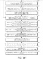
- FIGS. 5a and 5b are a flow chart illustrating one example of a method 500 for coding scalable video.
- determine if a pps_extension_flag e.g. pps_extension_present_flag
- the PPS multilayer extension flag is read or examined to determine if the pps_multilayer_extension should be parsed. In some cases, for example, when using an encoder, this step is referred to as signaling. It is understood that in the case of an encoder or encoding, the corresponding encoder-appropriate terminology is assumed.
- pps_extension_type_flag[1] is set, specifying that the pps_multilayer_extension syntax structure is present, the method proceeds 504 to the pps_multilayer_extension and the rest of the steps after 503 are processed.
- reference_layer_offset rLId is determined.
- a scaled_reference_offset_present_flag e.g. scaled_ref_layer_offset_present_flag
- scaled_ref_layer_offset_present_flag is checked to determine whether it is set to indicate that the scaled reference layer offset parameters are present.
- scaled_ref_layer_left_offset is determined.
- scaled_ref_layer_top_offset is determined.
- scaled_ref_layer right offset is determined.
- scaled_ref_layer_bottom_offset is determined.
- RefLayerHorizontalDeltaChroma ref_layer_horizontal_delta_chroma[rLId]
- RefLayerVerticalDeltaChroma ref_layer_vertical_delta_chroma[rLId]
- addX ScaleFactorX ⁇ phaseX + 4 > > 3
- addY ScaleFactorY ⁇ phaseY + 4 > > 3
- yRef16 yP ⁇ offsetY ⁇ ScaleFactorY + addY + 1 ⁇ ⁇ 11 > > 12 ⁇ deltaY
- FIG. 6 is a simplified block diagram that illustrates an example video coding system 10 that may utilize the techniques of this disclosure.
- video coder can refer to either or both video encoders and video decoders.
- video coding or “coding” may refer to video encoding and video decoding.
- video coding system 10 includes a source device 12 and a destination device 14.
- Source device 12 generates encoded video data. Accordingly, source device 12 may be referred to as a video encoding device.
- Destination device 14 may decode the encoded video data generated by source device 12. Accordingly, destination device 14 may be referred to as a video decoding device.
- Source device 12 and destination device 14 may be examples of video coding devices.
- Destination device 14 may receive encoded video data from source device 12 via a channel 16.
- Channel 16 may comprise a type of medium or device capable of moving the encoded video data from source device 12 to destination device 14 .
- channel 16 may comprise a communication medium that enables source device 12 to transmit encoded video data directly to destination device 14 in real-time.
- source device 12 may modulate the encoded video data according to a communication standard, such as a wireless communication protocol, and may transmit the modulated video data to destination device 14.
- the communication medium may comprise a wireless or wired communication medium, such as a radio frequency (RF) spectrum or one or more physical transmission lines.
- the communication medium may form part of a packet-based network, such as a local area network, a wide-area network, or a global network such as the Internet.
- the communication medium may include routers, switches, base stations, or other equipment that facilitates communication from source device 12 to destination device 14.
- channel 16 may correspond to a storage medium that stores the encoded video data generated by source device 12.
- source device 12 includes a video source 18, video encoder 20, and an output interface 22.
- output interface 22 may include a modulator/demodulator (modem) and/or a transmitter.
- video source 18 may include a source such as a video capture device, e.g., a video camera, a video archive containing previously captured video data, a video feed interface to receive video data from a video content provider, and/or a computer graphics system for generating video data, or a combination of such sources.
- Video encoder 20 may encode the captured, pre-captured, or computer-generated video data.
- the encoded video data may be transmitted directly to destination device 14 via output interface 22 of source device 12.
- the encoded video data may also be stored onto a storage medium or a file server for later access by destination device 14 for decoding and/or playback.
- destination device 14 includes an input interface 28, a video decoder 30, and a display device 32.
- input interface 28 may include a receiver and/or a modem.
- Input interface 28 of destination device 14 receives encoded video data over channel 16.
- the encoded video data may include a variety of syntax elements generated by video encoder 20 that represent the video data. Such syntax elements may be included with the encoded video data transmitted on a communication medium, stored on a storage medium, or stored a file server.
- Display device 32 may be integrated with or may be external to destination device 14.
- destination device 14 may include an integrated display device and may also be configured to interface with an external display device.
- destination device 14 may be a display device.
- display device 32 displays the decoded video data to a user.
- Video encoder 20 includes a resampling module 25 which may be configured to code (e.g., encode) video data in a scalable video coding scheme that defines at least one base layer and at least one enhancement layer. Resampling module 25 may resample at least some video data as part of an encoding process, wherein resampling may be performed in an adaptive manner using resampling filters. Likewise, video decoder 30 may also include a resampling module 35 similar to the resampling module 25 employed in the video encoder 20.
- Video encoder 20 and video decoder 30 may operate according to a video compression standard, such as the High Efficiency Video Coding (HEVC) standard.
- HEVC High Efficiency Video Coding
- the HEVC standard is being developed by the Joint Collaborative Team on Video Coding (JCT-VC) of ITU-T Video Coding Experts Group (VCEG) and ISO/IEC Motion Picture Experts Group (MPEG).
- JCT-VC Joint Collaborative Team on Video Coding
- VCEG Video Coding Experts Group
- MPEG ISO/IEC Motion Picture Experts Group
- a recent draft of the HEVC standard is described in Recommendation ITU-T H.265
- video encoder 20 and video decoder 30 may operate according to other proprietary or industry standards, such as the ITU-T H.264 standard, alternatively referred to as MPEG-4, Part 10, Advanced Video Coding (AVC), or extensions of such standards.
- the techniques of this disclosure are not limited to any particular coding standard or technique.
- Other examples of video compression standards and techniques include MPEG-2, ITU-T H.263 and proprietary or open source compression formats and related formats.
- Video encoder 20 and video decoder 30 may be implemented in hardware, software, firmware or any combination thereof.
- the video encoder 20 and decoder 30 may employ one or more processors, digital signal processors (DSPs), application specific integrated circuits (ASICs), field programmable gate arrays (FPGAs), discrete logic, or any combinations thereof.
- DSPs digital signal processors
- ASICs application specific integrated circuits
- FPGAs field programmable gate arrays
- a device may store instructions for the software in a suitable, non-transitory computer-readable storage medium and may execute the instructions in hardware using one or more processors to perform the techniques of this disclosure.
- Each of video encoder 20 and video decoder 30 may be included in one or more encoders or decoders, either of which may be integrated as part of a combined encoder/decoder (CODEC) in a respective device.
- CODEC combined encoder/decoder
- aspects of the subject matter described herein may be described in the general context of computer-executable instructions, such as program modules, being executed by a computer.
- program modules include routines, programs, objects, components, data structures, and so forth, which perform particular tasks or implement particular abstract data types.
- aspects of the subject matter described herein may also be practiced in distributed computing environments where tasks are performed by remote processing devices that are linked through a communications network.
- program modules may be located in both local and remote computer storage media including memory storage devices.
- Particular embodiments may be implemented in a non-transitory computer-readable storage medium for use by or in connection with the instruction execution system, apparatus, system, or machine.
- the computer-readable storage medium contains instructions for controlling a computer system to perform a method described by particular embodiments.
- the computer system may include one or more computing devices.
- the instructions, when executed by one or more computer processors, may be configured to perform that which is described in particular embodiments.
Description
- The present invention relates to a sampling filter process for scalable video coding. More specifically, the present invention relates to re-sampling using video data obtained from an encoder or decoder process, where the encoder or decoder process can be MPEG-4 Advanced Video Coding (AVC) or High Efficiency Video Coding (HEVC). Further, the present invention specifically relates to Scalable HEVC (SHVC) that includes a two layer video coding system.
- Scalable video coding (SVC) refers to video coding in which a base layer (BL), sometimes referred to as a reference layer, and one or more scalable enhancement layers (EL) are used. For SVC, the base layer can carry video data with a base level of quality. The one or more enhancement layers can carry additional video data to support higher spatial, temporal, and/or signal-to-noise SNR levels. Enhancement layers may be defined relative to a previously coded layer.
- The base layer and enhancement layers can have different resolutions. Upsampling filtering, sometimes referred to as resampling filtering, may be applied to the base layer in order to match a spatial aspect ratio or resolution of an enhancement layer. This process may be called spatial scalability. An upsampling filter set can be applied to the base layer, and one filter can be chosen from the set based on a phase (sometimes referred to as a fractional pixel shift). The phase may be calculated based on the ratio between base layer and enhancement layer picture resolutions.
- MINOO K ET AL, "AHG13: SHVC Upsampling with phase offset adjustment", 104. MPEG MEETING; 22-4-2013 - 26-4-2013; INCHEON; (MOTION PICTURE EXPERT GROUP OR ISO/IEC JTC1/SC29/WG11), 20 April 2013, discusses SHVC allowing for upsampling with phase offset adjustment to compensate for phase offsets introduced by downsampling or to maintain proper luma/chroma color space positions after upsampling. MINOO K ET AL, "On handling re-sampling phase offsets with fixed filters", 16. JCT-VC MEETING; 9-1-2014 - 17-1-2014; SAN JOSE; (JOINT COLLABORATIVE TEAM ON VIDEO CODING OF ISO/IEC JTC1/SC29/WG11 AND ITU-T SG.16), 10 January 2014, discusses an approach to signalling phase offsets to improve inter-layer prediction precision and hence the compression performance of SHEVC.
- Embodiments of the present invention provide methods, devices and systems for the upsampling process from BL resolution to EL resolution to implement the upsampling of
Fig. 2 . The upsampling process of embodiments of the present invention includes three separate modules, a first module to select input samples from the BL video signal, a second module to select a filter for filtering the samples, and a third module using phase filtering to filter the input samples to recreate video that approximates the EL resolution video. The filters of the third module can be selected from a set of fixed filters each with different phase. In these modules, the selection of the input samples and filters for generating the output samples are determined based upon a mapping between the EL sample positions and the corresponding BL sample positions. The embodiments included herein are related to the mapping or computation between the EL and the BL sample positions. One embodiment includes a system for scalable video coding, as defined in the appendedindependent claim 1. The invention is defined in the appended claims. - Further details of the present invention are explained with the help of the attached drawings in which:
-
Fig. 1 is a block diagram of components in a scalable video coding system with two layers; -
Fig. 2 illustrates an upsampling process that can be used to convert the base layer data to the full resolution layer data forFig. 1 ; -
Fig. 3 shows a block diagram of components for implementing the upsampling process ofFig. 2 ; -
Fig. 4 shows components of the select filter module and the filters, where the filters are selected from fixed or adaptive filters to apply a desired phase shift; -
Fig. 5a and5b is a simplified flow chart showing the process for determining the reference layer location based upon the syntax used in a method for coding scalable video. -
Fig. 6 is a simplified block diagram that illustrates an example video coding system. - An example of a scalable video coding system using two layers is shown in
Fig. 1 . In the system ofFig. 1 , one of the two layers is the Base Layer (BL) where a BL video is encoded in an Encoder E0, labeled 100, and decoded in a decoder D0, labeled 102, to produce a base layer video output BL out. The BL video is typically at a lower quality than the remaining layers, such as the Full Resolution (FR) layer that receives an input FR (y). The FR layer includes an encoder E1, labeled 104, and a decoder D1, labeled 106. In encoding in encoder E1 104 of the full resolution video, cross-layer (CL) information from theBL encoder 100 is used to produce enhancement layer (EL) information. The corresponding EL bitstream of the full resolution layer is then decoded indecoder D1 106 using the CL information fromdecoder D0 102 of the BL to output full resolution video, FR out. By using CL information in a scalable video coding system, the encoded information can be transmitted more efficiently in the EL than if the FR was encoded independently without the CL information. An example of coding that can use two layers shown inFig. 1 includes video coding using AVC and the Scalable Video Coding (SVC) extension of AVC, respectively. Another example that can use two layer coding is HEVC. -
Fig. 1 further showsblock 108 with a down-arrow r illustrating a resolution reduction from the FR to the BL to illustrate that the BL can be created by a downsampling of the FR layer data. Although a downsampling is shown by the arrow r ofblock 108Fig. 1 , the BL can be independently created without the downsampling process. Overall, the down arrow ofblock 108 illustrates that in spatial scalability, the base layer BL is typically at a lower spatial resolution than the full resolution FR layer. For example, when r = 2 and the FR resolution is 3840x2160, the corresponding BL resolution is 1920x1080. - The cross-layer CL information provided from the BL to the FR layer shown in
Fig. 1 illustrates that the CL information can be used in the coding of the FR video in the EL. In one example, the CL information includes pixel information derived from the encoding and decoding process of the BL. Examples of BL encoding and decoding are AVC and HEVC. Because the BL pictures are at a different spatial resolution than the FR pictures, a BL picture needs to be upsampled (or re-sampled) back to the FR picture resolution in order to generate a suitable prediction for the FR picture. -
Fig. 2 illustrates an upsampling process inblock 200 of data from the BL layer to the EL. The components of theupsampling block 200 can be included in either or both of the encoder E1 104 and thedecoder D1 106 of the EL of the video coding system ofFig. 1 . The BL data at resolution x that is input intoupsampling block 200 inFig. 2 is derived from one or more of the encoding and decoding processes of the BL. A BL picture is upsampled using the up-arrow r process ofblock 200 to generate the EL resolution output y' that can be used as a basis for prediction of the original FR input y. - The
upsampling block 200 works by interpolating from the BL data to recreate what is modified from the FR data. For instance, if every other pixel is dropped from the FR inblock 108 to create the lower resolution BL data, the dropped pixels can be recreated using theupsampling block 200 by interpolation or other techniques to generate the EL resolution output y' fromupsampling block 200. The data y' is then used to make encoding and decoding of the EL data more efficient. -
Fig. 3 shows a general block diagram for implementing an upsampling process ofFig. 2 for embodiments of the present invention. The upsampling or re-sampling process can be determined to minimize an error E (e.g. mean-squared error) between the upsampled data y' and the full resolution data y. The system ofFig. 3 includes a selectinput samples module 300 that samples an input video signal. The system further includes aselect filter module 302 to select a filter from the subsequent filterinput samples module 304 to upsample the selected input samples frommodule 300. - In
module 300, a set of input samples in a video signal x is first selected. In general, the samples can be a two-dimensional subset of samples in x, and a two-dimensional filter can be applied to the samples. Themodule 302 receives the data samples in x frommodule 300 and identifies the position of each sample from the data it receives, enablingmodule 302 to select an appropriate filter to direct the samples toward asubsequent filter module 304. The filter inmodule 304 is selected to filter the input samples, where the selected filter is chosen or configured to have a phase corresponding to the particular output sample location desired. - The filter
input samples module 304 can include separate row and column filters. The selection of filters is represented herein as filters h[n; p], where the filters can be separable along each row or column, and p denotes a phase index selection for the filter. The output of the filtering process using the selected filter h[n;p] on the selected input samples produces output value y'. -
Fig. 4 shows details of components for theselect sample module 302 ofFig. 3 (labeled 302a inFig. 4 ) and thefilters module 304 ofFig. 3 (labeled 304a inFig. 4 ) for a system with fixed filters. For separable filtering the input samples can be along a row or column of data. To supply a set of input samples from selectinput samples module 300, theselect filter module 302a includes aselect control 400 that identifies the input samples x[m] and provides a signal to aselector 402 that directs them through theselector 402 to a desired filter. Thefilter module 304a then includes the different filters h[n;p] that can be applied to the input samples, where the filter phase can be chosen among P phases from each row or column element depending on the output sample m desired. As shown, theselector 402 ofmodule 302a directs the input samples to a desired column or row filter in 304a based on the "Filter (n) SEL" signal fromselect control 400. A separateselect control 400 signal "Phase (p) SEL" selects the appropriate filter phase p for each of the row or column elements. Thefilter module 304a output produces the output y'[n]. - In
Fig. 4 , the outputs from individual filter components h[n;p] are shown added "+" to produce the output y'[n]. This illustrates that each box, e.g. h[0;p], represents one coefficient or number in a filter with phase p. Therefore, the filter with phase p is represented by all n+1 numbers in h[0,p], ..., h[n;p]. This is the filter that is applied to the selected input samples to produce an output value y'[n], for example, y'[0] = h[0,p]∗x[0] + h[1,p]∗x[1] + ... + h[n,p]∗x[n], requiring the addition function "+" as illustrated. As an alternative to adding inFig. 4 , the "+" could be replaced with a solid connection and the output y'[n] would be selected from one output of a bank of P filters representing the p phases, with the boxes h[n:p] inmodule 304a relabeled, for example, as h[n;0], h[n,1], ..., h[n,p-1] and now each box would have all the filter coefficients needed to form y'[n] without the addition element required. - In order to accommodate for offset and phase shift differences between the BL and EL samples, phase offset adjustment parameters can be signaled. Let a sample location relative to the top-left sample in the current EL picture be (xP, yP), and a sample location in the BL reference layer in units of 1/16-th sample relative to the top-left sample of the BL be (xRef16, yRef16). In "High efficiency video coding (HEVC)
scalable extension Draft 5," JCTVC-P1008_v4, January 2014 ("HEVC Draft 5"), the relationship between (xRef16, yRef16) and ( xP, yP) is given as follows:

- The sample position (xRef16, yRef16) is used to select the input samples and the filters used in computing the output sample values as specified in
HEVC Draft 5. - The variables offsetX, addX, offsetY, and addY specify scaled reference layer offset and phase parameters in the horizontal and vertical directions, variables phaseX and phaseY specify reference layer phase offset parameters in the horizontal and vertical directions, and variables ScaleFactorX and ScaleFactorY are computed based on the ratio of the reference layer to the scaled reference layer width and height. These variables are computed based upon phase offset parameters specified in [1]. In particular, the offset parameters offsetX and offsetY are computed as:


ScaledRefLayerLeftOffset = scaled_ref_layer_left_offset[rLId] << 1
ScaledRefLayerTopOffset = scaled_ref_layer_top_offset[rLId] << 1
ScaledRefLayerRightOffset = scaled_ref_layer_right_offset[rLId] << 1
ScaledRefLayerBottomOffset = scaled_ref_layer_bottom_offset[rLId] << 1
where rLId specifies the scaled reference layer picture Id. The variables ScaledRefLayerLeftOffset, ScaledRefLayerTopOffset, ScaledRefLayerRightOffset, and ScaledRefLayerBottomOffset specify offsets in two pixel unit resolution based on the values of the syntax elements scaled_ref_layer_left_offset[rLId], scaled_ref_layer_top_offset[rLId], scaled_ref_layer_right_offset[rLId], and scaled_ref_layer_bottom_offset[rLId]. - Table 1 illustrates the signaling of these syntax elements in
HEVC Draft 5 at the SPS multilayer extension layer.Table 1: Current Syntax for signaling scaled layer offsets. sps_ multilayer_ extension( ) { Descriptor inter_view_mv_vert_constraint_flag u(1) num_scaled_ref_layer_offsets ue(v) for( i = 0; i < num_scaled_ref_layer_offsets; i++) { scaled_ref_layer_id[ i ] u(6) scaled_ref_layer_left_offset[ scaled_ref_layer_id[ i ] ] se(v) scaled_ref_layer_top_offset[ scaled_ref_layer_id[ i ] ] se(v) scaled_ref_layer_right_offset[ scaled_ref_layer_id[ i ] ] se(v) scaled_ref_layer_bottom_offset[ scaled_ref_layer_id[ i ] ] se(v) vert_phase_position_enable_flag[scaled _ref_layer_id[ i ] ] u(1) } } - In Table 1, the signaling occurs at the SPS level. Table 1 shows current syntax for signaling scaled layer offsets (shown in bold type). In Table 1, the four syntax elements listed below are signaled.
- scaled_ref_layer_left_offset[scaled_ref_layer_id[i]]
scaled_ref_layer_top_offset[scaled_ref_layer_id[i]]
scaled_ref_layer_right_offset[scaled_ref_layer_id[i]]
scaled_ref_layer_bottom_offset[scaled_ref_layer_id[i]] - In
HEVC Draft 5, the syntax elements are defined as follows: - scaled_ref_layer_id[i] specifies the nuh_layer_id value of the associated inter-layer picture for which scaled_ref_layer_left_offset[i], scaled_ref_layer_top_offset[i], scaled_ref_layer_right_offset[i] and scaled_ref_layer_bottom_offset[i] are specified. The value of scaled_ref_layer_id[i] shall be less than the nuh_layer_id of any layer for which this SPS is the active SPS.
- scaled_ref_layer_left_offset[scaled_ref_layer_id[i]] specifies the horizontal offset between the top-left luma sample of the associated inter-layer picture with nuh layer id equal to scaled_ref_layer_id[i] and the top-left luma sample of the current picture in units of two luma samples. When not present, the value of scaled_ref_layer_left_offset[scaled_ref_layer_id[i]] is inferred to be equal to 0.
- scaled_ref_layer_top_offset[scaled_ref_layer_id[i]] specifies the vertical offset between the top-left luma sample of the associated inter-layer picture with nuh_layer_id equal to scaled_ref_layer_id[i] and the top-left luma sample of the current picture in units of two luma samples. When not present, the value of scaled_ref_layer_top_offset[scaled_ref_layer_id[i]] is inferred to be equal to 0.
- scaled_ref_layer_right_offset[scaled_ref_layer_id[i]] specifies the horizontal offset between the bottom-right luma sample of the associated inter-layer picture with nuh layer id equal to scaled_ref_layer_id[i] and the bottom-right luma sample of the current picture in units of two luma samples. When not present, the value of scaled_ref_layer_right_offset[scaled_ref_layer_id[i]] is inferred to be equal to 0.
- scaled_ref_layer_bottom_offset[scaled_ref_layer_id[i]] specifies the vertical offset between the bottom-right luma sample of the associated inter-layer picture with nuh layer id equal to scaled_ref_layer_id[i] and the bottom-right luma sample of the current picture in units of two luma samples. When not present, the value of scaled_ref_layer_bottom_offset[scaled_ref_layer_id[i]] is inferred to be equal to 0.
- While the offset parameters are signaled at the SPS level, it is desirable to signal below the sequence level in order to accommodate other applications and operations such as interlace/progressive scalability and pan and scan. In addition, it is desirable to increase the resolution of the offset for proper BL and EL alignment.
- In order to accommodate other applications such as interlace/progressive scalability and to increase the resolution for BL and EL alignment, it is proposed that the phase offset adjustment parameters in Tables 2 and 3 be signaled. It is also possible to signal at other levels such as the slice level. Other variations are also possible, such as a flag signaling whether or not offset parameters are signaled at all, or per dimension or color component. Note that fractional pel accuracy of the phase offset parameters can be given in 1/16, 1/4, or 1/2, etc.
- In the proposed method, the scaled reference layer offset parameters are signaled at the PPS level. In Table 2, the pps_multilayer_extension syntax is parsed if a pps_extension_type_flag[1] (e.g. pps_multilayer_extension_flag) is set. Table 3 shows the scaled_ref_layer_id, scaled_ref_layer_left_offset, scaled_ref_layer_top_offset, scaled_ref_layer_right_offset and scaled_ref_layer_bottom_offset syntax elements signaled in the pps_multilayer_extension.
- The resolution of the scaled reference layer offset can be increased from 2-integer pel. The original coarser resolution allows for selection of a region in the scaled reference layer, while the additional proposed finer resolution allows for finer local phase offset adjustment between layers. Table 3 shows an example of the signaling of the proposed additional phase offset parameters:
- scaled_ref_layer_left_phase[scaled_ref_layer_id[i]] specifies the horizontal luma offset between nuh layer id equal to scaled_ref_layer_id[i] and the current picture in units of ½ luma samples. This is a signed value between -2 to +2. When not present, the value of scaled_ref_layer_left_phase[scaled_ref_layer_id[i]] is inferred to be equal to 0.
- scaled_ref_layer_top_phase[scaled_ref_layer_id[i]] specifies the vertical luma offset between nuh_layer_id equal to scaled_ref_layer_id[i] and the current picture in units of ½ luma samples. This is a signed value between -2 to +2. When not present, the value of scaled_ref_layer_top_phase[scaled_ref_layer_id[i]] is inferred to be equal to 0.
- ref_layer_horizontal_delta[scaled_ref_layer_id[i]] specifies the horizontal luma offset between nuh_layer_id equal to scaled_ref_layer_id[i] and the current picture in units of 1/8 luma samples. This is a signed value between -8 to 8. When not present, the value of ref_layer_horizontal_delta[scaled_ref_layer_id[i]] is inferred to be equal to 0.
- ref_layer_vertical_delta[scaled_ref_layer_id[i]] specifies the vertical luma offset between nuh_layer_id equal to scaled_ref_layer_id[i] and the current picture in units of 1/8 luma samples. This is a signed value between -8 to +8. When not present, the value of ref_layer_vertical_delta[scaled_ref_layer_id[i]] is inferred to be equal to 0.
- ref_layer_horizontal_delta_chroma[scaled_ref_layer_id[i]] specifies the horizontal offset between the chroma samples and luma samples in nuh layer id equal to scaled_ref_layer_id[i] in units of ¼ luma samples. This is an unsigned value between 0 to 4. When not present, the value of ref_layer_horizontal_delta_chroma[scaled_ref_layer_id[i]] is inferred to be equal to 2.
- ref_layer_vertical_delta_chroma[scaled_ref_layer_id[i]] specifies the vertical offset between the chroma samples and luma samples in nuh layer id equal to scaled_ref_layer_id[i] in units of ¼ luma samples. This is an unsigned value between 0 to 4. When not present, the value of ref_layer_vertical_delta_chroma[scaled_ref_layer_id[i]] is inferred to be equal to 2.
- scaled_ref_layer_left_phase_chroma specifies the horizontal chroma offset relative to luma in units of ¼ luma samples. This is an unsigned value between 0 to 4. When not present, the value of scaled_ref_layer_left_phase_chroma is inferred to be equal to 2.
- scaled_ref_layer_top_phase_chroma specifies the vertical chroma offset relative to luma in units of ¼ luma samples. This is an unsigned value between 0 to 4. When not present, the value of scaled_ref_layer_top_phase_chroma is inferred to be equal to 2.
- The additional syntax elements are used to provide finer alignment between the layers. One example of the use of the syntax is as follows:
- ScaledRefLayerLeftPhase = scaled_ref_layer_left_phase[rLId]
- ScaledRefLayerTopPhase = scaled_ref_layer_top_phase[rLId]
- RefLayerHorizontalDelta = ref_layer_horizontal_delta[rLId]
- RefLayerVerticalDelta = ref_layer_vertical_delta[rLId]
- RefLayerHorizontalDeltaChroma = ref_layer_horizontal_delta_chroma[rLId]
- RefLayerVerticalDeltaChroma = ref_layer_vertical_delta_chroma[rLId]


- The scaled reference layer phase offset parameters scaled_ref_layer_left_phase, scaled_ref_layer_left_phase_chroma, scaled_ref_layer_top_phase, and scaled_ref_layer_top_phase_chroma provide additional independent finer level or resolution over the previous scaled reference layer phase offset parameters scaled_ref_layer_left_offset, scaled_ref_layer_top_offset, scaled_ref_layer_right_offset and scaled_ref_layer_bottom_offset. In addition, the reference layer phase offset parameters ref_layer_horizontal_delta, ref_layer_vertical_delta, ref_layer_horizontal_delta_chroma and ref_layer_vertical_delta_chroma provide finer reference layer phase offset resolution.
Table 2: Proposed syntax for activating PPS multilayer extension. pic_parameter_set_rbsp( ) { Descriptor pps_pic_parameter_set_id ue(v) pps_ seq_parameter_set_id ue(v) ... pps_extension_flag u(1) if( pps_extension_flag ) { for ( i = 0; i < 8; i++ ) pps_extension_type_flag[ i ] u(1) if( pps_extension_type_flag[ 0 ]) poc_reset_info_present_flag u(1) if( pps_extension_type_flag[ 1 ] ) pps_multilayer_extension( ) if( pps_extension_type_flag[ 7] ) while(more_rbsp_data( ) ) pps_extension_data_flag u(1) } rbsp trailing bits( ) } Table 3: Proposed syntax for signaling offsets at PPS multilayer extension. pps_multilayer_ extension( ) { Descriptor num_scaled_ref_layer_offsets ue(v) for( i = 0; i < num_scaled_ref_layer_offsets; i++ ) { scaled_ref_layer_id[ i ] u(6) scaled_ref_layer_left_offset[ scaled_ref_layer_id[ i ] ] se(v) scaled_ref_layer_top_offset[ scaled_ref_layer_id[ i ] ] se(v) scaled_ref_layer_right_offset[ scaled_ref_layer_id[ i ] ] se(v) scaled_ref_layer_bottom_offset[ scaled_ref_layer_id[ i ] ] se(v) scaled_ref_layer_left_phase[ scaled_ref_layer_id[ i ] ] se(v) scaled_ref_layer_top_phase[ scaled_ref_layer_id[ i ] ] se(v) ref_layer_horizontal_delta[ scaled_ref_layer_id[ i ] ] se(v) ref_layer_vertical_delta[ scaled_ref_layer_id[ i ] ] se(v) ref_layer_horizontal_delta_chroma [ scaled_ref_layer_id[ i ] ] ue(v) ref_ layer_vertical_delta_chroma [scaled_ref_layer_id[ i ] ] ue(v) } scaled_ref_layer_left_phase_chroma ue(v) scaled_ref_layer_top_phase_chroma ue(v) } - The proposed syntax allows for interlace to progressive scalability and finer alignment between layers. Example syntax was given to illustrate how additional phase offset parameters in both scaled reference layer and the reference layer can be used for alignment between layers.
- In one proposed approach, the resolution of the scaled reference layer offset is increased from 2-integer pel. The original coarser resolution allows for selection of a region in the scale reference layer, while the additional proposed finer resolution allows for finer local phase offset between layers.
-
FIGS. 5a and5b are a flow chart illustrating one example of amethod 500 for coding scalable video. Atblock 501 within the Picture Parameter set RBSP syntax, determine if a pps_extension_flag (e.g. pps_extension_present_flag) is set. At 502, the PPS multilayer extension flag is read or examined to determine if the pps_multilayer_extension should be parsed. In some cases, for example, when using an encoder, this step is referred to as signaling. It is understood that in the case of an encoder or encoding, the corresponding encoder-appropriate terminology is assumed. At 503, if pps_extension_type_flag[1] is set, specifying that the pps_multilayer_extension syntax structure is present, the method proceeds 504 to the pps_multilayer_extension and the rest of the steps after 503 are processed. - At
block 506, reference_layer_offset rLId is determined. A scaled_reference_offset_present_flag (e.g. scaled_ref_layer_offset_present_flag) is checked to determine whether it is set to indicate that the scaled reference layer offset parameters are present. - If the flag is set, at
block 508, scaled_ref_layer_left_offset is determined. Next atblock 509, scaled_ref_layer_top_offset is determined. Atblock 510, scaled_ref_layer right offset is determined. Atblock 511, scaled_ref_layer_bottom_offset is determined. - Next, at
block 514, determine ScaledRefLayerOffsets using: - ScaledRefLayerLeftOffset = scaled_ref_layer_left_offset[rLId] << 1,
- ScaledRefLayerTopOffset = scaled_ref_layer_top_offset[rLId] << 1,
- ScaledRefLayerRightOffset = scaled_ref_layer_right_offset[rLId] << 1,
- ScaledRefLayerBottomOffset = scaled_ref_layer_bottom_offset[rLId] << 1.
- At
decision 516 check if scaled_reference_phase_present_flag is set to indicate that the reference phase offset parameters are present - If flag is set, At
block 518, determine: - ScaledRefLayerLeftPhase = scaled_ref_layer_left_phase[rLId]
- ScaledRefLayerTopPhase = scaled_ref_layer_top_phase[rLId]
- At
block 520, determine
RefLayerHorizontalDelta = ref_layer_horizontal_delta[rLId]
RefLayerVerticalDelta = ref_layer_vertical_delta[rLId] - Next, at
block 522, determine
RefLayerHorizontalDeltaChroma = ref_layer_horizontal_delta_chroma[rLId]
RefLayerVerticalDeltaChroma = ref_layer_vertical_delta_chroma[rLId] - At
block 524, determine: - scaled_ref_layer_left_phase_chroma
- scaled_ref_layer_top_phase_chroma
- And then at
block 526, determine offsetX and offsetY using:

- At
block 528, determine phaseX and phaseY using: - phaseX = (cIdx = = 0) ? (ScaledRefLayerLeftPhase <<2) : (ScaledRefLayerLeftPhase <<1 + scaled_ref_layer_left_phase_chroma)
- phaseY = (cIdx = = 0) ? (ScaledRefLayerTopPhase <<2) : (ScaledRefLayerTopPhase <<1 + scaled_ref_layer_top_phase_chroma)
- Next, at
block 530, determine deltaX and deltaY using:
block 532 determine deltaY using:
- Next at
block 534, determine addX and addY using:

- Next, at
block 536 determinexRef16 using 
- At
block 538 determineyRef16 
- Finally, at
block 540, provide xRef16 and yRef16 for use in selecting filters and input samples, for example inFigure 3 . -
FIG. 6 is a simplified block diagram that illustrates an examplevideo coding system 10 that may utilize the techniques of this disclosure. As used described herein, the term "video coder" can refer to either or both video encoders and video decoders. In this disclosure, the terms "video coding" or "coding" may refer to video encoding and video decoding. - As shown in
FIG. 6 ,video coding system 10 includes asource device 12 and adestination device 14. Source device 12generates encoded video data. Accordingly,source device 12 may be referred to as a video encoding device.Destination device 14 may decode the encoded video data generated bysource device 12. Accordingly,destination device 14 may be referred to as a video decoding device.Source device 12 anddestination device 14 may be examples of video coding devices. -
Destination device 14 may receive encoded video data fromsource device 12 via achannel 16.Channel 16 may comprise a type of medium or device capable of moving the encoded video data fromsource device 12 todestination device 14. In one example,channel 16 may comprise a communication medium that enablessource device 12 to transmit encoded video data directly todestination device 14 in real-time. - In this example,
source device 12 may modulate the encoded video data according to a communication standard, such as a wireless communication protocol, and may transmit the modulated video data todestination device 14. The communication medium may comprise a wireless or wired communication medium, such as a radio frequency (RF) spectrum or one or more physical transmission lines. The communication medium may form part of a packet-based network, such as a local area network, a wide-area network, or a global network such as the Internet. The communication medium may include routers, switches, base stations, or other equipment that facilitates communication fromsource device 12 todestination device 14. In another example,channel 16 may correspond to a storage medium that stores the encoded video data generated bysource device 12. - In the example of
FIG. 6 ,source device 12 includes avideo source 18,video encoder 20, and anoutput interface 22. In some cases,output interface 22 may include a modulator/demodulator (modem) and/or a transmitter. Insource device 12,video source 18 may include a source such as a video capture device, e.g., a video camera, a video archive containing previously captured video data, a video feed interface to receive video data from a video content provider, and/or a computer graphics system for generating video data, or a combination of such sources. -
Video encoder 20 may encode the captured, pre-captured, or computer-generated video data. The encoded video data may be transmitted directly todestination device 14 viaoutput interface 22 ofsource device 12. The encoded video data may also be stored onto a storage medium or a file server for later access bydestination device 14 for decoding and/or playback. - In the example of
FIG. 6 ,destination device 14 includes an input interface 28, avideo decoder 30, and adisplay device 32. In some cases, input interface 28 may include a receiver and/or a modem. Input interface 28 of destination device 14receives encoded video data overchannel 16. The encoded video data may include a variety of syntax elements generated byvideo encoder 20 that represent the video data. Such syntax elements may be included with the encoded video data transmitted on a communication medium, stored on a storage medium, or stored a file server. -
Display device 32 may be integrated with or may be external todestination device 14. In some examples, destination device14 may include an integrated display device and may also be configured to interface with an external display device. In other examples,destination device 14 may be a display device. In general,display device 32 displays the decoded video data to a user. -
Video encoder 20 includes aresampling module 25 which may be configured to code (e.g., encode) video data in a scalable video coding scheme that defines at least one base layer and at least one enhancement layer.Resampling module 25 may resample at least some video data as part of an encoding process, wherein resampling may be performed in an adaptive manner using resampling filters. Likewise,video decoder 30 may also include aresampling module 35 similar to theresampling module 25 employed in thevideo encoder 20. -
Video encoder 20 andvideo decoder 30 may operate according to a video compression standard, such as the High Efficiency Video Coding (HEVC) standard. The HEVC standard is being developed by the Joint Collaborative Team on Video Coding (JCT-VC) of ITU-T Video Coding Experts Group (VCEG) and ISO/IEC Motion Picture Experts Group (MPEG). A recent draft of the HEVC standard is described in Recommendation ITU-T H.265 | International Standard ISO/IEC 23008-2, High efficiency video coding,version 2, October 2014. - Additionally or alternatively,
video encoder 20 andvideo decoder 30 may operate according to other proprietary or industry standards, such as the ITU-T H.264 standard, alternatively referred to as MPEG-4,Part 10, Advanced Video Coding (AVC), or extensions of such standards. The techniques of this disclosure, however, are not limited to any particular coding standard or technique. Other examples of video compression standards and techniques include MPEG-2, ITU-T H.263 and proprietary or open source compression formats and related formats. -
Video encoder 20 andvideo decoder 30 may be implemented in hardware, software, firmware or any combination thereof. For example, thevideo encoder 20 anddecoder 30 may employ one or more processors, digital signal processors (DSPs), application specific integrated circuits (ASICs), field programmable gate arrays (FPGAs), discrete logic, or any combinations thereof. When thevideo encoder 20 anddecoder 30 are implemented partially in software, a device may store instructions for the software in a suitable, non-transitory computer-readable storage medium and may execute the instructions in hardware using one or more processors to perform the techniques of this disclosure. Each ofvideo encoder 20 andvideo decoder 30 may be included in one or more encoders or decoders, either of which may be integrated as part of a combined encoder/decoder (CODEC) in a respective device. - Aspects of the subject matter described herein may be described in the general context of computer-executable instructions, such as program modules, being executed by a computer. Generally, program modules include routines, programs, objects, components, data structures, and so forth, which perform particular tasks or implement particular abstract data types. Aspects of the subject matter described herein may also be practiced in distributed computing environments where tasks are performed by remote processing devices that are linked through a communications network. In a distributed computing environment, program modules may be located in both local and remote computer storage media including memory storage devices.
- Also, it is noted that some embodiments have been described as a process which is depicted as a flow diagram or block diagram. Although each may describe the operations as a sequential process, many of the operations can be performed in parallel or concurrently. A process may have additional steps not included in the figure.
- Particular embodiments may be implemented in a non-transitory computer-readable storage medium for use by or in connection with the instruction execution system, apparatus, system, or machine. The computer-readable storage medium contains instructions for controlling a computer system to perform a method described by particular embodiments. The computer system may include one or more computing devices. The instructions, when executed by one or more computer processors, may be configured to perform that which is described in particular embodiments.
- Although the subject matter has been described in language specific to structural features and/or methodological acts, it is to be understood that the subject matter defined in the appended claims is not necessarily limited to the specific features or acts described above.
Claims (3)
- A system for scalable video coding, comprising:a first coding layer arrangement comprising modules for coding video with a base resolution to provide a first coding layer;a second coding layer arrangement comprising modules for coding video with an enhanced resolution having a higher resolution than a base resolution to provide a second coding layer;wherein pixel values in the second coding layer are predicted based on pixel values in the first coding layer;wherein the prediction of a value at a pixel location in the second coding layer is based on a corresponding value at a pixel location in the first coding layer;wherein the corresponding pixel location in the first coding layer is computed based on the pixel location in the second coding layer;wherein the pixel location in the second coding layer is (xP, yP);wherein the corresponding pixel location in the first coding layer is computed as (xRefl6, yRefl6) in units of 1/16-th sample relative to the top-left sample of the first coding layer, where:variables ScaleFactorX and ScaleFactorY are computed based on the ratio of the reference layer to the scaled reference layer width and height;variable cldx specifies the color component index and the values SubWidthC and SubHeightC are specified depending on the chroma format sampling structure;and where:


 ScaledRefLayerLeftOffset = scaled_ref_layer_left_offset[rLId] << 1;ScaledRefLayerTopOffset = scaled_ref_layer_top_offset[rLId] << 1;scaled_ref_layer_left_offset[rLId] specifies a horizontal offset between a top-left luma sample of an associated inter-layer picture with nuh_layer_id equal to rLId and the top-left luma sample of the current picture in units of two luma samples;scaled_ref_layer_top_offset[rLId] specifies the vertical offset between the top-left luma sample of an associated inter-layer picture with nuh_layer_id equal to rLId and the top-left luma sample of the current picture in units of two luma samples; andwherein the signaling of scaled_ref_layer_left_offset, and scaled_ref_layer_top_offset occurs at the PPS level,and where:


 ScaledRefLayerLeftPhase = scaled_ref_layer_left_phase[rLId];ScaledRefLayerTopPhase = scaled_ref_layer_top_phase[rLId];RefLayerHorizontalDelta = ref_layer_horizontal_delta[rLId];RefLayerVerticalDelta = ref_layer_vertical_delta[rLId];scaled_ref_layer_left_phase[rLId] specifies a horizontal luma offset between nuh_layer_id equal to rLId and the current picture in units of ½ luma samples;scaled_ref_layer_top_phase[rLId] specifies a vertical luma offset between nuh layer _id equal to rLId and the current picture in units of ½ luma samples;scaled_ref_layer_left_phase_chroma specifies the horizontal chroma offset relative to luma in units of 1/4 luma samples;scaled_ref_layer_top_phase_chroma specifies the vertical chroma offset relative to luma in units of 1/4 luma samples;ref_layer_horizontal_delta[rLId] specifies a horizontal luma offset between nuh layer _id equal to rLId and the current picture in units of 1/8 luma samples;ref_layer_vertical_delta[rLId] specifies a vertical luma offset between nuh_layer_id equal to rLId and the current picture in units of 1/8 luma samples;RefLayerHorizontalDeltaChroma = ref_layer_horizontal_delta_chroma[rLId];RefLayerVerticalDeltaChroma = ref_layer_vertical_delta_chroma[rLId];ref_layer_horizonal_delta_chroma[rLId] specifies the horizontal offset between the chroma samples and luma samples in nuh_layer_id equal to rLId in unit of 1/4 samples;ref_layer_vertical_delta_chroma[rLId] specifies the vertical offset between the chroma samples and luma samples in nuh_layer_id equal to rLId in unit of 1/4 samples; andwherein the signaling of scaled_ref_layer_left_phase, scaled_ref_layer_top_phase, ref_layer_horizontal_delta, ref_layer_vertical_delta, ref_layer_horizontal_delta_chroma, ref_layer_vertical_delta_chroma, scaled_ref_layer_left_phase_chroma and scaled_ref_layer_top_phase_chroma occurs at the PPS level.
 - The system of claim 1, wherein the system is a High Efficiency Video Coding, HEVC, standard system and scaled_ref_layer_left_offset, scaled_ref_layer_top_offset, scaled_ref_layer_left_phase, scaled_ref_layer_top_phase, ref_layer_horizontal_delta, and ref_layer_vertical_delta are signaled in a pps_multilayer_extension syntax that is conditional on a pps_extension_type_flag[1] flag.
- The system of claim 1, wherein the system is a High Efficiency Video Coding, HEVC, standard system and scaled_ref_layer_left_offset and scaled_ref_layer_top_offset are signaled conditional on a scaled_reference_offset_present_flag flag, and
scaled_ref_layer_left_phase, scaled_ref_layer_top_phase, ref_layer_horizontal_delta, ref_layer_vertical_delta, rel_layer_horizontal_delta_chroma, ref_layer_vertical_delta_chroma, scaled_ref_layer_left_phase_chroma and scaled_ref_layer_top_phase_chroma are signaled conditional on a scaled_reference_phase_present_flag flag.
Priority Applications (1)
| Application Number | Priority Date | Filing Date | Title |
|---|---|---|---|
| EP20160514.4A EP3700218A1 (en) | 2014-03-18 | 2015-03-18 | Scalable video coding using reference and scaled reference layer offsets |
Applications Claiming Priority (2)
| Application Number | Priority Date | Filing Date | Title |
|---|---|---|---|
| US201461955123P | 2014-03-18 | 2014-03-18 | |
| PCT/US2015/021341 WO2015143090A1 (en) | 2014-03-18 | 2015-03-18 | Scalable video coding using reference and scaled reference layer offsets |
Related Child Applications (1)
| Application Number | Title | Priority Date | Filing Date |
|---|---|---|---|
| EP20160514.4A Division EP3700218A1 (en) | 2014-03-18 | 2015-03-18 | Scalable video coding using reference and scaled reference layer offsets |
Publications (2)
| Publication Number | Publication Date |
|---|---|
| EP3120562A1 EP3120562A1 (en) | 2017-01-25 |
| EP3120562B1 true EP3120562B1 (en) | 2020-03-04 |
Family
ID=57588802
Family Applications (2)
| Application Number | Title | Priority Date | Filing Date |
|---|---|---|---|
| EP15714726.5A Active EP3120562B1 (en) | 2014-03-18 | 2015-03-18 | Scalable video coding using reference and scaled reference layer offsets |
| EP20160514.4A Pending EP3700218A1 (en) | 2014-03-18 | 2015-03-18 | Scalable video coding using reference and scaled reference layer offsets |
Family Applications After (1)
| Application Number | Title | Priority Date | Filing Date |
|---|---|---|---|
| EP20160514.4A Pending EP3700218A1 (en) | 2014-03-18 | 2015-03-18 | Scalable video coding using reference and scaled reference layer offsets |
Country Status (1)
| Country | Link |
|---|---|
| EP (2) | EP3120562B1 (en) |
Families Citing this family (1)
| Publication number | Priority date | Publication date | Assignee | Title |
|---|---|---|---|---|
| CA3144792A1 (en) * | 2019-06-24 | 2020-12-30 | Huawei Technologies Co., Ltd. | Sample distance calculation for geometric partition mode |
Family Cites Families (1)
| Publication number | Priority date | Publication date | Assignee | Title |
|---|---|---|---|---|
| US10448032B2 (en) * | 2012-09-04 | 2019-10-15 | Qualcomm Incorporated | Signaling of down-sampling location information in scalable video coding |
-
2015
- 2015-03-18 EP EP15714726.5A patent/EP3120562B1/en active Active
- 2015-03-18 EP EP20160514.4A patent/EP3700218A1/en active Pending
Non-Patent Citations (1)
| Title |
|---|
| None * |
Also Published As
| Publication number | Publication date |
|---|---|
| EP3700218A1 (en) | 2020-08-26 |
| EP3120562A1 (en) | 2017-01-25 |
Similar Documents
| Publication | Publication Date | Title |
|---|---|---|
| US11375215B2 (en) | Reference layer and scaled reference layer offsets for scalable video coding | |
| US11394986B2 (en) | Scalable video coding using reference and scaled reference layer offsets | |
| US11218712B2 (en) | On reference layer and scaled reference layer offset parameters for inter-layer prediction in scalable video coding | |
| US20140301488A1 (en) | Derivation of resampling filters for scalable video coding | |
| US20220038721A1 (en) | Cross-component quantization in video coding | |
| CN114600461A (en) | Computation for multiple codec tools | |
| EP3120562B1 (en) | Scalable video coding using reference and scaled reference layer offsets | |
| US10218970B2 (en) | Resampling filters for scalable video coding with phase offset adjustment and signaling of same | |
| US20240137536A1 (en) | Reference layer and scaled reference layer offsets for scalable video coding | |
| US20240137537A1 (en) | On reference layer and scaled reference layer offset parameters for inter-layer prediction in scalable video coding | |
| US20150271495A1 (en) | Scalable Video Coding using Phase Offset Flag Signaling | |
| KR20220063279A (en) | Encoder and decoder, encoding method and decoding method for reference picture resampling extension | |
| CN113545060A (en) | Empty tile coding in video coding | |
| EP3149942A1 (en) | Reference layer offset parameters for inter-layer prediction in scalable video coding | |
| WO2024079383A1 (en) | An apparatus, a method and a computer program for volumetric video | |
| KR20240049612A (en) | Methods, devices and media for video processing |
Legal Events
| Date | Code | Title | Description |
|---|---|---|---|
| STAA | Information on the status of an ep patent application or granted ep patent |
Free format text: STATUS: THE INTERNATIONAL PUBLICATION HAS BEEN MADE |
|
| PUAI | Public reference made under article 153(3) epc to a published international application that has entered the european phase |
Free format text: ORIGINAL CODE: 0009012 |
|
| STAA | Information on the status of an ep patent application or granted ep patent |
Free format text: STATUS: REQUEST FOR EXAMINATION WAS MADE |
|
| 17P | Request for examination filed |
Effective date: 20161017 |
|
| AK | Designated contracting states |
Kind code of ref document: A1 Designated state(s): AL AT BE BG CH CY CZ DE DK EE ES FI FR GB GR HR HU IE IS IT LI LT LU LV MC MK MT NL NO PL PT RO RS SE SI SK SM TR |
|
| AX | Request for extension of the european patent |
Extension state: BA ME |
|
| DAV | Request for validation of the european patent (deleted) | ||
| DAX | Request for extension of the european patent (deleted) | ||
| STAA | Information on the status of an ep patent application or granted ep patent |
Free format text: STATUS: EXAMINATION IS IN PROGRESS |
|
| 17Q | First examination report despatched |
Effective date: 20181112 |
|
| GRAP | Despatch of communication of intention to grant a patent |
Free format text: ORIGINAL CODE: EPIDOSNIGR1 |
|
| STAA | Information on the status of an ep patent application or granted ep patent |
Free format text: STATUS: GRANT OF PATENT IS INTENDED |
|
| INTG | Intention to grant announced |
Effective date: 20191023 |
|
| GRAS | Grant fee paid |
Free format text: ORIGINAL CODE: EPIDOSNIGR3 |
|
| GRAA | (expected) grant |
Free format text: ORIGINAL CODE: 0009210 |
|
| STAA | Information on the status of an ep patent application or granted ep patent |
Free format text: STATUS: THE PATENT HAS BEEN GRANTED |
|
| AK | Designated contracting states |
Kind code of ref document: B1 Designated state(s): AL AT BE BG CH CY CZ DE DK EE ES FI FR GB GR HR HU IE IS IT LI LT LU LV MC MK MT NL NO PL PT RO RS SE SI SK SM TR |
|
| REG | Reference to a national code |
Ref country code: GB Ref legal event code: FG4D |
|
| REG | Reference to a national code |
Ref country code: CH Ref legal event code: EP |
|
| REG | Reference to a national code |
Ref country code: AT Ref legal event code: REF Ref document number: 1241797 Country of ref document: AT Kind code of ref document: T Effective date: 20200315 |
|
| REG | Reference to a national code |
Ref country code: DE Ref legal event code: R096 Ref document number: 602015048117 Country of ref document: DE |
|
| REG | Reference to a national code |
Ref country code: IE Ref legal event code: FG4D |
|
| PG25 | Lapsed in a contracting state [announced via postgrant information from national office to epo] |
Ref country code: FI Free format text: LAPSE BECAUSE OF FAILURE TO SUBMIT A TRANSLATION OF THE DESCRIPTION OR TO PAY THE FEE WITHIN THE PRESCRIBED TIME-LIMIT Effective date: 20200304 Ref country code: NO Free format text: LAPSE BECAUSE OF FAILURE TO SUBMIT A TRANSLATION OF THE DESCRIPTION OR TO PAY THE FEE WITHIN THE PRESCRIBED TIME-LIMIT Effective date: 20200604 Ref country code: RS Free format text: LAPSE BECAUSE OF FAILURE TO SUBMIT A TRANSLATION OF THE DESCRIPTION OR TO PAY THE FEE WITHIN THE PRESCRIBED TIME-LIMIT Effective date: 20200304 |
|
| REG | Reference to a national code |
Ref country code: NL Ref legal event code: MP Effective date: 20200304 |
|
| PG25 | Lapsed in a contracting state [announced via postgrant information from national office to epo] |
Ref country code: BG Free format text: LAPSE BECAUSE OF FAILURE TO SUBMIT A TRANSLATION OF THE DESCRIPTION OR TO PAY THE FEE WITHIN THE PRESCRIBED TIME-LIMIT Effective date: 20200604 Ref country code: HR Free format text: LAPSE BECAUSE OF FAILURE TO SUBMIT A TRANSLATION OF THE DESCRIPTION OR TO PAY THE FEE WITHIN THE PRESCRIBED TIME-LIMIT Effective date: 20200304 Ref country code: SE Free format text: LAPSE BECAUSE OF FAILURE TO SUBMIT A TRANSLATION OF THE DESCRIPTION OR TO PAY THE FEE WITHIN THE PRESCRIBED TIME-LIMIT Effective date: 20200304 Ref country code: GR Free format text: LAPSE BECAUSE OF FAILURE TO SUBMIT A TRANSLATION OF THE DESCRIPTION OR TO PAY THE FEE WITHIN THE PRESCRIBED TIME-LIMIT Effective date: 20200605 Ref country code: LV Free format text: LAPSE BECAUSE OF FAILURE TO SUBMIT A TRANSLATION OF THE DESCRIPTION OR TO PAY THE FEE WITHIN THE PRESCRIBED TIME-LIMIT Effective date: 20200304 |
|
| REG | Reference to a national code |
Ref country code: LT Ref legal event code: MG4D |
|
| PG25 | Lapsed in a contracting state [announced via postgrant information from national office to epo] |
Ref country code: NL Free format text: LAPSE BECAUSE OF FAILURE TO SUBMIT A TRANSLATION OF THE DESCRIPTION OR TO PAY THE FEE WITHIN THE PRESCRIBED TIME-LIMIT Effective date: 20200304 |
|
| PG25 | Lapsed in a contracting state [announced via postgrant information from national office to epo] |
Ref country code: ES Free format text: LAPSE BECAUSE OF FAILURE TO SUBMIT A TRANSLATION OF THE DESCRIPTION OR TO PAY THE FEE WITHIN THE PRESCRIBED TIME-LIMIT Effective date: 20200304 Ref country code: PT Free format text: LAPSE BECAUSE OF FAILURE TO SUBMIT A TRANSLATION OF THE DESCRIPTION OR TO PAY THE FEE WITHIN THE PRESCRIBED TIME-LIMIT Effective date: 20200729 Ref country code: CZ Free format text: LAPSE BECAUSE OF FAILURE TO SUBMIT A TRANSLATION OF THE DESCRIPTION OR TO PAY THE FEE WITHIN THE PRESCRIBED TIME-LIMIT Effective date: 20200304 Ref country code: LT Free format text: LAPSE BECAUSE OF FAILURE TO SUBMIT A TRANSLATION OF THE DESCRIPTION OR TO PAY THE FEE WITHIN THE PRESCRIBED TIME-LIMIT Effective date: 20200304 Ref country code: RO Free format text: LAPSE BECAUSE OF FAILURE TO SUBMIT A TRANSLATION OF THE DESCRIPTION OR TO PAY THE FEE WITHIN THE PRESCRIBED TIME-LIMIT Effective date: 20200304 Ref country code: IS Free format text: LAPSE BECAUSE OF FAILURE TO SUBMIT A TRANSLATION OF THE DESCRIPTION OR TO PAY THE FEE WITHIN THE PRESCRIBED TIME-LIMIT Effective date: 20200704 Ref country code: SK Free format text: LAPSE BECAUSE OF FAILURE TO SUBMIT A TRANSLATION OF THE DESCRIPTION OR TO PAY THE FEE WITHIN THE PRESCRIBED TIME-LIMIT Effective date: 20200304 Ref country code: EE Free format text: LAPSE BECAUSE OF FAILURE TO SUBMIT A TRANSLATION OF THE DESCRIPTION OR TO PAY THE FEE WITHIN THE PRESCRIBED TIME-LIMIT Effective date: 20200304 Ref country code: SM Free format text: LAPSE BECAUSE OF FAILURE TO SUBMIT A TRANSLATION OF THE DESCRIPTION OR TO PAY THE FEE WITHIN THE PRESCRIBED TIME-LIMIT Effective date: 20200304 |
|
| REG | Reference to a national code |
Ref country code: CH Ref legal event code: PL |
|
| REG | Reference to a national code |
Ref country code: AT Ref legal event code: MK05 Ref document number: 1241797 Country of ref document: AT Kind code of ref document: T Effective date: 20200304 |
|
| REG | Reference to a national code |
Ref country code: DE Ref legal event code: R097 Ref document number: 602015048117 Country of ref document: DE |
|
| REG | Reference to a national code |
Ref country code: BE Ref legal event code: MM Effective date: 20200331 |
|
| PG25 | Lapsed in a contracting state [announced via postgrant information from national office to epo] |
Ref country code: MC Free format text: LAPSE BECAUSE OF FAILURE TO SUBMIT A TRANSLATION OF THE DESCRIPTION OR TO PAY THE FEE WITHIN THE PRESCRIBED TIME-LIMIT Effective date: 20200304 Ref country code: LU Free format text: LAPSE BECAUSE OF NON-PAYMENT OF DUE FEES Effective date: 20200318 |
|
| PLBE | No opposition filed within time limit |
Free format text: ORIGINAL CODE: 0009261 |
|
| STAA | Information on the status of an ep patent application or granted ep patent |
Free format text: STATUS: NO OPPOSITION FILED WITHIN TIME LIMIT |
|
| PG25 | Lapsed in a contracting state [announced via postgrant information from national office to epo] |
Ref country code: LI Free format text: LAPSE BECAUSE OF NON-PAYMENT OF DUE FEES Effective date: 20200331 Ref country code: CH Free format text: LAPSE BECAUSE OF NON-PAYMENT OF DUE FEES Effective date: 20200331 Ref country code: IE Free format text: LAPSE BECAUSE OF NON-PAYMENT OF DUE FEES Effective date: 20200318 Ref country code: DK Free format text: LAPSE BECAUSE OF FAILURE TO SUBMIT A TRANSLATION OF THE DESCRIPTION OR TO PAY THE FEE WITHIN THE PRESCRIBED TIME-LIMIT Effective date: 20200304 Ref country code: AT Free format text: LAPSE BECAUSE OF FAILURE TO SUBMIT A TRANSLATION OF THE DESCRIPTION OR TO PAY THE FEE WITHIN THE PRESCRIBED TIME-LIMIT Effective date: 20200304 Ref country code: IT Free format text: LAPSE BECAUSE OF FAILURE TO SUBMIT A TRANSLATION OF THE DESCRIPTION OR TO PAY THE FEE WITHIN THE PRESCRIBED TIME-LIMIT Effective date: 20200304 |
|
| 26N | No opposition filed |
Effective date: 20201207 |
|
| PG25 | Lapsed in a contracting state [announced via postgrant information from national office to epo] |
Ref country code: PL Free format text: LAPSE BECAUSE OF FAILURE TO SUBMIT A TRANSLATION OF THE DESCRIPTION OR TO PAY THE FEE WITHIN THE PRESCRIBED TIME-LIMIT Effective date: 20200304 Ref country code: BE Free format text: LAPSE BECAUSE OF NON-PAYMENT OF DUE FEES Effective date: 20200331 Ref country code: SI Free format text: LAPSE BECAUSE OF FAILURE TO SUBMIT A TRANSLATION OF THE DESCRIPTION OR TO PAY THE FEE WITHIN THE PRESCRIBED TIME-LIMIT Effective date: 20200304 |
|
| PG25 | Lapsed in a contracting state [announced via postgrant information from national office to epo] |
Ref country code: FR Free format text: LAPSE BECAUSE OF NON-PAYMENT OF DUE FEES Effective date: 20200504 |
|
| PG25 | Lapsed in a contracting state [announced via postgrant information from national office to epo] |
Ref country code: TR Free format text: LAPSE BECAUSE OF FAILURE TO SUBMIT A TRANSLATION OF THE DESCRIPTION OR TO PAY THE FEE WITHIN THE PRESCRIBED TIME-LIMIT Effective date: 20200304 Ref country code: MT Free format text: LAPSE BECAUSE OF FAILURE TO SUBMIT A TRANSLATION OF THE DESCRIPTION OR TO PAY THE FEE WITHIN THE PRESCRIBED TIME-LIMIT Effective date: 20200304 Ref country code: CY Free format text: LAPSE BECAUSE OF FAILURE TO SUBMIT A TRANSLATION OF THE DESCRIPTION OR TO PAY THE FEE WITHIN THE PRESCRIBED TIME-LIMIT Effective date: 20200304 |
|
| PG25 | Lapsed in a contracting state [announced via postgrant information from national office to epo] |
Ref country code: MK Free format text: LAPSE BECAUSE OF FAILURE TO SUBMIT A TRANSLATION OF THE DESCRIPTION OR TO PAY THE FEE WITHIN THE PRESCRIBED TIME-LIMIT Effective date: 20200304 Ref country code: AL Free format text: LAPSE BECAUSE OF FAILURE TO SUBMIT A TRANSLATION OF THE DESCRIPTION OR TO PAY THE FEE WITHIN THE PRESCRIBED TIME-LIMIT Effective date: 20200304 |
|
| REG | Reference to a national code |
Ref country code: GB Ref legal event code: 732E Free format text: REGISTERED BETWEEN 20220714 AND 20220720 |
|
| REG | Reference to a national code |
Ref country code: DE Ref legal event code: R081 Ref document number: 602015048117 Country of ref document: DE Owner name: ARRIS INTERNATIONAL IP LTD, SALTAIRE, GB Free format text: FORMER OWNER: ARRIS ENTERPRISES LLC, SUWANEE, GA., US Ref country code: DE Ref legal event code: R082 Ref document number: 602015048117 Country of ref document: DE Representative=s name: MURGITROYD GERMANY PATENTANWALTSGESELLSCHAFT M, DE Ref country code: DE Ref legal event code: R081 Ref document number: 602015048117 Country of ref document: DE Owner name: ANDREW WIRELESS SYSTEMS UK LTD., GB Free format text: FORMER OWNER: ARRIS ENTERPRISES LLC, SUWANEE, GA., US |
|
| PGFP | Annual fee paid to national office [announced via postgrant information from national office to epo] |
Ref country code: GB Payment date: 20230327 Year of fee payment: 9 Ref country code: DE Payment date: 20230329 Year of fee payment: 9 |
|
| P01 | Opt-out of the competence of the unified patent court (upc) registered |
Effective date: 20230530 |
|
| REG | Reference to a national code |
Ref country code: DE Ref legal event code: R081 Ref document number: 602015048117 Country of ref document: DE Owner name: ANDREW WIRELESS SYSTEMS UK LTD., GB Free format text: FORMER OWNER: ARRIS INTERNATIONAL IP LTD, SALTAIRE, WEST YORKSHIRE, GB |