EP3119699B1 - Packaging unit with lock and method for packing products - Google Patents
Packaging unit with lock and method for packing products Download PDFInfo
- Publication number
- EP3119699B1 EP3119699B1 EP15726373.2A EP15726373A EP3119699B1 EP 3119699 B1 EP3119699 B1 EP 3119699B1 EP 15726373 A EP15726373 A EP 15726373A EP 3119699 B1 EP3119699 B1 EP 3119699B1
- Authority
- EP
- European Patent Office
- Prior art keywords
- packaging unit
- locking element
- cover part
- front surface
- length
- Prior art date
- Legal status (The legal status is an assumption and is not a legal conclusion. Google has not performed a legal analysis and makes no representation as to the accuracy of the status listed.)
- Active
Links
Images


Classifications
-
- B—PERFORMING OPERATIONS; TRANSPORTING
- B65—CONVEYING; PACKING; STORING; HANDLING THIN OR FILAMENTARY MATERIAL
- B65D—CONTAINERS FOR STORAGE OR TRANSPORT OF ARTICLES OR MATERIALS, e.g. BAGS, BARRELS, BOTTLES, BOXES, CANS, CARTONS, CRATES, DRUMS, JARS, TANKS, HOPPERS, FORWARDING CONTAINERS; ACCESSORIES, CLOSURES, OR FITTINGS THEREFOR; PACKAGING ELEMENTS; PACKAGES
- B65D85/00—Containers, packaging elements or packages, specially adapted for particular articles or materials
- B65D85/30—Containers, packaging elements or packages, specially adapted for particular articles or materials for articles particularly sensitive to damage by shock or pressure
- B65D85/32—Containers, packaging elements or packages, specially adapted for particular articles or materials for articles particularly sensitive to damage by shock or pressure for eggs
- B65D85/324—Containers with compartments made of pressed material
-
- B—PERFORMING OPERATIONS; TRANSPORTING
- B65—CONVEYING; PACKING; STORING; HANDLING THIN OR FILAMENTARY MATERIAL
- B65D—CONTAINERS FOR STORAGE OR TRANSPORT OF ARTICLES OR MATERIALS, e.g. BAGS, BARRELS, BOTTLES, BOXES, CANS, CARTONS, CRATES, DRUMS, JARS, TANKS, HOPPERS, FORWARDING CONTAINERS; ACCESSORIES, CLOSURES, OR FITTINGS THEREFOR; PACKAGING ELEMENTS; PACKAGES
- B65D2203/00—Decoration means, markings, information elements, contents indicators
- B65D2203/02—Labels
Definitions
- the present invention relates to a packaging unit made of moulded pulp for products like eggs and similar products like kiwis and tomatoes, for example.
- Egg cases, containers or cartons known in practice are generally fabricated from carton made from moulded pulp originating from paper material. Such units comprise a bottom part, provided with compartments for individual products, and a cover part that is often hingedly connected to the bottom part. Products like eggs are transported in these units and displayed on shelves in supermarkets, for example.
- the lock that is provided to secure the cover part to the bottom part in the closed position of the packaging unit needs to be sufficiently stable.
- the lock is not always sufficiently stable, such that the cover part is not sufficiently locked to the bottom part in the closed position of the packaging unit. This may result in product damage and even product loss during transport and/or storage.
- the present invention has for its object to obviate or at least reduce the above stated problems in known packaging units such as egg cases or egg cartons.
- the present invention provides for this purpose a packaging unit according to claim 1.
- the cover part is hingedly connected to the bottom part on the rear side thereof.
- a lock is provided on the front side comprising a first locking element on the bottom part and a second locking element on the cover part.
- the first locking element extends upwardly from the bottom part, thereby defining a cam structure with an at least partly downwardly facing locking plane having a length and a width.
- the first locking element is hingedly connected to the bottom part and capable of some rotating movement.
- the cam is provided with a closed outer contour/surface without openings the plane corresponds to the at least partly downwardly facing locking surface of the cam.
- the cam When the packaging unit is in a closed position, the cam partly extends through an opening that is provided in the front surface of the cover part. This provides a lock capable of locking the packaging unit according to the invention to prevent unintentional opening of the packaging unit.
- the second locking element having a length and a width, extends inwardly from the front surface of the cover part over a certain length. This further improves the locking function and more specifically improves the stability of the lock over a broad range of conditions involving forces acting on the packaging unit, wear, and production tolerances.
- the second locking element is preferably shaped as a lip or edge that is preferably provided at or near the bottom edge of the opening in the front surface of the cover part.
- the first and second locking elements are configured such that the locking elements are capable of engaging each other over the length of the locking element, more specifically the second locking element is configured such that it is capable of engaging, with its length, the first locking element in a locking state of the packaging unit.
- This enables an increase in the effective locking area, i.e. the surface of the first and second locking elements that may contact each other, thereby improving locking security.
- the second locking element comes into contact with the at least partially downward facing locking plane of the first locking element when an upwards acting force is applied to the cover part, while it is not the intention to open the packaging unit. This improves the locking function and stability of the packaging unit.
- the ratio of the length of the cam and the length of the second locking element is in the range of 1.25-3 mm, preferably in the range of 1.5-2.5 mm, more preferably in the range of 1.6-2.2 mm, and most preferably the ratio is about 1.8 mm.
- the second locking element that is preferably shaped as a lip or edge, has a length of about 3.5-8 mm, more preferably, the length is about 5 mm. It is shown that providing a significant length, preferably 5 mm, for the second locking element contributes to guaranteeing a sufficient locking function when the packaging unit according to the present invention is used in practice with disturbing effects. This further improves the stability of the lock of the packaging unit, thereby reducing the risk of damaging products therein.
- the plane of the first locking element is provided with an angle relative to the horizontal in the range of 3°-20°, preferably in the range of 5°-15°, and most preferably the angle is about 10°.
- the second locking element is confronted with a locking force that has a component in an inward direction of the packaging unit. This further stabilises the lock of the packaging unit.
- the second locking element is provided at an angle relative to the front surface of the cover part in the range of 20°-60°, preferably in the range of 30°-50°, and most preferably the angle is about 40°.
- This angle is relative to the front surface of the cover part.
- the first and second locking elements are arranged such that an increasing contact surface between the locking elements is achieved when an upwards directed force acts on the cover part in case of unintentional opening of the packaging unit. As an effect of such force the second locking element bends relative to the front surface of the cover part. Increasing the contact surface increases the strength of the locking function, thereby improving the stability of the lock.
- both the first and the second locking elements are provided at their respective angles, and the combination of these two features further improves the stability of the lock beyond the sum of the individual effects.
- the front surface of the cover part comprises two parts that are provided substantially above each other in vertical direction at an angle relative to each other, with a first lower part and a second part above the first part comprising the one or more openings in the front surface.
- a visual effect is achieved, such that a consumer has a good view on the (stack of) packaging units irrespective of the position of the consumer relative to the packaging unit.
- the lock capability of handling forces acting under various angles on the packaging unit is improved.
- a slightly inwardly inclined second part of the front surface is provided such that the contribution of the front surface of the cover part to the correct functioning of the lock is improved.
- the first locking element is provided with a front surface comprising an embossing.
- the consumer can be provided with visual information about the egg.
- This visual information may relate to the contents of the packaging unit and/or indication of a location for opening the packaging unit.
- the packaging unit comprises a label that is provided on the cover part, wherein the label comprises a cut to enable the first locking element to partly extend through the opening in the front surface of the cover part.
- the first locking element is capable of extending through the opening in the front surface.
- the cut can be shaped as an opening such that the first locking element extends through the opening in the front surface of the cover part and the label that is provided thereon.
- a groove-shaped cut, incision or slit is provided that enables the first locking element to slightly deform the label.
- the consumer is provided with information that the lock is correctly achieved. Furthermore, this provides the consumer with a visual indication of where, and how, to open the packaging unit.
- the cut comprises a curved cut that is configured to enable the cam to partly extend through the opening in the cover part. More specifically, the curved cut is preferably positioned relative to the cam such that in a closed position of the packaging unit the cam defines a buckling or deflected part in the label and keeping the cam substantially behind the label as seen in a front view of the packaging unit in a closed position thereof.
- This further enhances the display surface and provides an additional three-dimensional effect on the label.
- this three-dimensional effect is further enhanced by providing the cam with an egg-shape. This is particular useful in case of packing egg-products for a visual indication to consumers of the products inside the packaging unit.
- the egg-shaped cam distributes forces over the label in all relevant directions such that the risk of the label cracking or bursting when closing the packaging unit is significantly reduced.
- the curved cut comprises a circular shape with one curve radius. Providing a single curve radius provides a cut that is well defined and is capable of distributing forces acting on the label in all relevant directions to prevent cracking or bursting of the label.
- the curved cut comprises more than one curve radius. Providing more than one curve radius enables providing a cut with any desired length. This provides additional flexibility for the dimensions of the packaging unit.
- the first locking element is formed by moulding and/or pressing and is provided with a closed surface or closed outer contour.
- the first locking element By designing the first locking element as a cam that is preferably provided with a nose shape, the first locking element can be formed during the manufacturing process involving moulding and/or pressing. This also enables providing the cam shaped first locking element with a closed surface or closed outer contour, i.e. substantially without openings in the contact surfaces of the lock. This improves the contact between the downward facing plane/surface of the first locking element and the second locking element.
- the present invention further relates to a method for packing products like eggs, comprising the steps of providing a packaging unit as described above, and placing therein one or more of the products.
- a packaging unit 2 ( Figures 1-2 ) comprises a first unit 2a and a second unit 2b. Each unit comprises a bottom part 4 with a front surface 6, two side surfaces 8, a back side 10, and a bottom side 12.
- a cover part 14 is hingedly connected with hinge 16 to bottom part 4 to allow cover part 14 to move relatively to bottom part 4 between an open and a closed position.
- Cover part 14 further comprises front surface 18, two side surfaces 20, a back side surface 22 and a top surface 24.
- bottom part 4 product receiving compartments 26 having contours matching at least partially the outer contours of the products, like eggs, kiwis and tomatoes, for example.
- Support cones 28 are provided to add stability and strength to packaging unit 2.
- connection 32 connects the twin packages 2A, 2B. It will be understood that all features shown for the twin pack configuration 2 can also be used in other configurations, including more conventional packaging units including a unit comprising 6, 10, 12 or any other number of compartments for receiving products like eggs.
- FIG. 3A and B Several alternative embodiments of a packaging unit can be envisaged ( Figure 3A and B ), including a packaging unit 34 that is provided with a label 36 wherein label 36 comprises cut 38.
- Lock 30 may extend through cut 38 and/or push part of label 36 slightly forward when packaging unit 34 is in a closed position.
- cut 38 can be applied, including the groove-shaped cut in a substantially horizontal direction as illustrated in Figure 3A , as well as U-shaped cuts that enable part of label 36 to slightly be pushed upwards by lock 30 when packaging unit 34 is in a closed position.
- a further alternative embodiment for packaging unit 40 comprises label 42 wherein an opening 44 ( Figure 3A ) is provided.
- alternative units 34, 40 are shown in one twin pack.
- front surface of lock 30 is provided with an embossment 46.
- the shape of embossment 46 can be related to the product provided inside packaging unit 40, such as an egg-shape, or provide further information to the consumer, such as where to open packaging unit 40.
- Alternative embodiments 134, 140 ( Figure 3 B) with lock 130 comprise labels 136, 142 with a ⁇ -shaped cut 138 and a +-shaped cut 138, respectively. It will be understood that other shapes are also possible including U-, V-, ⁇ -, and ⁇ -shaped cuts.
- cut 138 is embodied as an incision.
- cut 138 can be provided as a cut-away with some label material being removed.
- FIG. 3 C Alternative packaging unit 202 ( Figure 3 C) is illustrated in a twin pack-configuration.
- Unit 234 is provided with label 236, wherein label 236 comprises cut 238.
- label 236 comprises cut 238.
- Cam 231 of lock 230 may extend through cut 238 and/or push part of label 236 slightly forward in area 240 when packaging unit 234 is in a closed position.
- area 40 will typically have an egg-shape corresponding with the shape of cam 231.
- cut 238 comprises a single radius R1, extending in height over distance y1 and in width direction over distance d1. It will be understood that several shapes of cut 238 can be applied.
- Unit 242 is provided with label 244 comprising alternative cut 246 with at least two different radii R2a and R2b, extending over distances y2 and d2 defining area 247.
- a further alternative embodiment for packaging unit 248 comprises label 250, wherein cut 252 is provided ( Figure 3 D) that extends over distances y3 and d3. Cut 252 is on both ends provided with cross-cuts 254. Cross-cuts 254 enlarge area 256 by increasing distance y3 enabling further buckling or deflection of label 250 caused by cam 231.
- Unit 258 comprises label 260 with cut 262 having at least two radii R4a and R4b, and cross-cuts 264. Distances y4 and d4 define area 266.
- alternative units 248, 258 are shown in one twin pack.
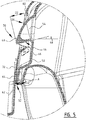
- Lock 30 ( Figures 4-5 ) comprise a nose-shaped cam 48 acting as first locking element.
- Cam 48 is provided on flap 50 that is hingedly connected by connection 52 to bottom part 4 of packaging unit 2.
- connection 52 is capable of a slightly rotating movement A.
- cam 48 defines a closed outer surface or outer contour defining a chamber 54.
- the substantially downward facing surface 56 of cam 48 is in the illustrated embodiment a substantially closed surface without openings.
- cam 48 partly extends through opening 58 that is provided in the front surface 18 of cover part 14.
- the upper edge 60 of opening 58 is provided at a small angle and is slightly pushed inwards.
- Front surface 18 of cover part 18 is provided with lower part 62 that in the closed position of packaging unit 2 extends substantially vertical.
- a second part 64 is provided directly above first part 62 at an inwards inclined angle ⁇ relative to vertical 70.
- the upper edge of second part 64 defines the lower edge 66 of opening 58 and acts as second locking element.
- Edge or lip 66 of this second locking element extends over a distance D1 and is provided at an angle ⁇ relative to the second part 64 of front surface 18.
- surface 56 of cam 48 is provided at an angle ⁇ relative to horizontal 68.
- Surface 56 extends substantially inward over a length D2. In the illustrated embodiment, length D2 is about two times the length D1 of lip 66.
- ⁇ is about 30°
- ⁇ is about 5°
- ⁇ is about 12°
- Distance D1 is about 5 mm
- distance D2 is about 9 to 10 mm. It will be understood that other configurations and dimensions will also be possible in accordance with the present invention.
- lip 66 is provided at a somewhat larger angle relative to horizontal 68 as compared to surface 56.
- lip 66 will contact surface 56 and the contact surface between the two locking elements 48, 66 will increase with an increasing upwards directed force. This improves the stability of lock 30.
- a chamber 54 is provided by moulding and/or pressing such that plane 56 preferably provides a closed surface. It will be understood that other alternative configurations are also possible in accordance with the invention.
Landscapes
- Engineering & Computer Science (AREA)
- Mechanical Engineering (AREA)
- Packaging Frangible Articles (AREA)
- Packages (AREA)
- Auxiliary Devices For And Details Of Packaging Control (AREA)
- Buffer Packaging (AREA)
Description
- The present invention relates to a packaging unit made of moulded pulp for products like eggs and similar products like kiwis and tomatoes, for example.
- Egg cases, containers or cartons known in practice are generally fabricated from carton made from moulded pulp originating from paper material. Such units comprise a bottom part, provided with compartments for individual products, and a cover part that is often hingedly connected to the bottom part. Products like eggs are transported in these units and displayed on shelves in supermarkets, for example.
-
DE 20 2013 011 737 U1 , which discloses a packaging unit according to the preamble of claim 1, andNL 7810282 - During the transport of the packaging units and the stacked display of packaging units, the lock that is provided to secure the cover part to the bottom part in the closed position of the packaging unit needs to be sufficiently stable. In practice, due to the forces acting on the packaging units, wear, and production tolerances etc. the lock is not always sufficiently stable, such that the cover part is not sufficiently locked to the bottom part in the closed position of the packaging unit. This may result in product damage and even product loss during transport and/or storage.
- The present invention has for its object to obviate or at least reduce the above stated problems in known packaging units such as egg cases or egg cartons.
- The present invention provides for this purpose a packaging unit according to claim 1.
- Having a packaging unit with a bottom part and a cover part enables transport and display of products without damaging the products. This is especially relevant in case of vulnerable products like eggs. In a preferred embodiment, the cover part is hingedly connected to the bottom part on the rear side thereof. On the front side a lock is provided comprising a first locking element on the bottom part and a second locking element on the cover part.
- The first locking element extends upwardly from the bottom part, thereby defining a cam structure with an at least partly downwardly facing locking plane having a length and a width. Preferably, the first locking element is hingedly connected to the bottom part and capable of some rotating movement. In case the cam is provided with a closed outer contour/surface without openings the plane corresponds to the at least partly downwardly facing locking surface of the cam.
- When the packaging unit is in a closed position, the cam partly extends through an opening that is provided in the front surface of the cover part. This provides a lock capable of locking the packaging unit according to the invention to prevent unintentional opening of the packaging unit.
- To further enhance the locking function and increase the stability of the lock during transport and/or storage and/or display, the second locking element, having a length and a width, extends inwardly from the front surface of the cover part over a certain length. This further improves the locking function and more specifically improves the stability of the lock over a broad range of conditions involving forces acting on the packaging unit, wear, and production tolerances.
- The second locking element is preferably shaped as a lip or edge that is preferably provided at or near the bottom edge of the opening in the front surface of the cover part. The first and second locking elements are configured such that the locking elements are capable of engaging each other over the length of the locking element, more specifically the second locking element is configured such that it is capable of engaging, with its length, the first locking element in a locking state of the packaging unit. This enables an increase in the effective locking area, i.e. the surface of the first and second locking elements that may contact each other, thereby improving locking security. Preferably, the second locking element comes into contact with the at least partially downward facing locking plane of the first locking element when an upwards acting force is applied to the cover part, while it is not the intention to open the packaging unit. This improves the locking function and stability of the packaging unit.
- Providing the second locking element over a certain length improves the stability of the lock. The ratio of the length of the cam and the length of the second locking element is in the range of 1.25-3 mm, preferably in the range of 1.5-2.5 mm, more preferably in the range of 1.6-2.2 mm, and most preferably the ratio is about 1.8 mm. By providing the second locking element with a length extending at least partly in the similar direction as the substantial downward facing plane of the cam over a substantial distance, an improved stability of the lock is achieved. This prevents product damage during transport, storage and display that may be caused by accidently opening the packaging unit and damaging the products inside, for example.
- Preferably, the second locking element that is preferably shaped as a lip or edge, has a length of about 3.5-8 mm, more preferably, the length is about 5 mm. It is shown that providing a significant length, preferably 5 mm, for the second locking element contributes to guaranteeing a sufficient locking function when the packaging unit according to the present invention is used in practice with disturbing effects. This further improves the stability of the lock of the packaging unit, thereby reducing the risk of damaging products therein.
- In a presently preferred embodiment according to the present invention, the plane of the first locking element is provided with an angle relative to the horizontal in the range of 3°-20°, preferably in the range of 5°-15°, and most preferably the angle is about 10°.
- By providing the at least partly downward facing plane or surface of the first locking element in closed position of the packaging unit at an angle to the horizontal, a self-locking effect is achieved. In this embodiment the second locking element is confronted with a locking force that has a component in an inward direction of the packaging unit. This further stabilises the lock of the packaging unit.
- Preferably, the second locking element is provided at an angle relative to the front surface of the cover part in the range of 20°-60°, preferably in the range of 30°-50°, and most preferably the angle is about 40°. This angle is relative to the front surface of the cover part. In a presently preferred embodiment according to the invention the first and second locking elements are arranged such that an increasing contact surface between the locking elements is achieved when an upwards directed force acts on the cover part in case of unintentional opening of the packaging unit. As an effect of such force the second locking element bends relative to the front surface of the cover part. Increasing the contact surface increases the strength of the locking function, thereby improving the stability of the lock.
- In a presently preferred embodiment, both the first and the second locking elements are provided at their respective angles, and the combination of these two features further improves the stability of the lock beyond the sum of the individual effects.
- In a presently preferred embodiment according to the present invention, the front surface of the cover part comprises two parts that are provided substantially above each other in vertical direction at an angle relative to each other, with a first lower part and a second part above the first part comprising the one or more openings in the front surface.
- By providing parts of the front surface of the cover part of an angle to each other a visual effect is achieved, such that a consumer has a good view on the (stack of) packaging units irrespective of the position of the consumer relative to the packaging unit. Furthermore, by having a first lower part of the front surface extending in a substantial vertical direction and providing a second part above the first part with the second part comprising the opening that is provided in the front surface, the lock capability of handling forces acting under various angles on the packaging unit is improved. Preferably a slightly inwardly inclined second part of the front surface is provided such that the contribution of the front surface of the cover part to the correct functioning of the lock is improved. This effect is even further improved in combination with providing the second locking element at an angle, as mentioned before, such that especially the self-locking and/or stability effect of the locking function is enhanced.
- In a further presently preferred embodiment according the present invention, the first locking element is provided with a front surface comprising an embossing.
- By providing an embossing at the front surface of the first locking element that in a closed position of the packaging unit at least partly extends through the opening in the front surface of the cover part, the consumer can be provided with visual information about the egg. This visual information may relate to the contents of the packaging unit and/or indication of a location for opening the packaging unit.
- In a further preferred embodiment according to the present invention, the packaging unit comprises a label that is provided on the cover part, wherein the label comprises a cut to enable the first locking element to partly extend through the opening in the front surface of the cover part.
- By providing the label with a cut, incision or slit, the first locking element is capable of extending through the opening in the front surface. The cut can be shaped as an opening such that the first locking element extends through the opening in the front surface of the cover part and the label that is provided thereon. Alternatively, a groove-shaped cut, incision or slit is provided that enables the first locking element to slightly deform the label. As an optional advantageous effect, the consumer is provided with information that the lock is correctly achieved. Furthermore, this provides the consumer with a visual indication of where, and how, to open the packaging unit.
- In a presently preferred embodiment the cut comprises a curved cut that is configured to enable the cam to partly extend through the opening in the cover part. More specifically, the curved cut is preferably positioned relative to the cam such that in a closed position of the packaging unit the cam defines a buckling or deflected part in the label and keeping the cam substantially behind the label as seen in a front view of the packaging unit in a closed position thereof. This further enhances the display surface and provides an additional three-dimensional effect on the label. Preferably this three-dimensional effect is further enhanced by providing the cam with an egg-shape. This is particular useful in case of packing egg-products for a visual indication to consumers of the products inside the packaging unit. Furthermore, the egg-shaped cam distributes forces over the label in all relevant directions such that the risk of the label cracking or bursting when closing the packaging unit is significantly reduced. In one of the presently preferred embodiments according to the present invention the curved cut comprises a circular shape with one curve radius. Providing a single curve radius provides a cut that is well defined and is capable of distributing forces acting on the label in all relevant directions to prevent cracking or bursting of the label. In an alternative preferred embodiment according to the present invention the curved cut comprises more than one curve radius. Providing more than one curve radius enables providing a cut with any desired length. This provides additional flexibility for the dimensions of the packaging unit.
- In a presently preferred embodiment, the first locking element is formed by moulding and/or pressing and is provided with a closed surface or closed outer contour.
- By designing the first locking element as a cam that is preferably provided with a nose shape, the first locking element can be formed during the manufacturing process involving moulding and/or pressing. This also enables providing the cam shaped first locking element with a closed surface or closed outer contour, i.e. substantially without openings in the contact surfaces of the lock. This improves the contact between the downward facing plane/surface of the first locking element and the second locking element.
- The present invention further relates to a method for packing products like eggs, comprising the steps of providing a packaging unit as described above, and placing therein one or more of the products.
- Such method provides the same effect and advantages as described with respect of the packaging unit. In fact, the method can be used with a large number of different embodiments of the packaging units according to the invention.
- Further advantages, features and details of the invention are elucidated on a basis of preferred embodiments thereof, wherein reference is made to the accompanying drawings, in which:
-
Fig. 1 shows an embodiment of the packaging unit in an open position; -
Fig. 2 shows a front view of the packaging unit ofFigure 1 ; -
Fig. 3A and B show a combination of two different embodiments in the twin pack unit; -
Fig. 3C shows a front view of the packaging unit ofFigure 1 in an alternative embodiment with two different embodiments in the twin pack configuration; -
Fig. 3D shows a further alternative embodiment of the packaging unit according to the invention with two different embodiments in the twin pack configuration; -
Fig. 4 shows a cross-section of the packaging unit ofFigures 1-2 ; and -
Fig. 5 shows a detail of the lock ofFigure 4 . - A packaging unit 2 (
Figures 1-2 ) comprises afirst unit 2a and asecond unit 2b. Each unit comprises abottom part 4 with a front surface 6, two side surfaces 8, aback side 10, and abottom side 12. In the illustrated embodiment, acover part 14 is hingedly connected withhinge 16 tobottom part 4 to allowcover part 14 to move relatively tobottom part 4 between an open and a closed position. Coverpart 14 further comprisesfront surface 18, twoside surfaces 20, aback side surface 22 and atop surface 24. - On the inside of
bottom part 4 product receiving compartments 26 are provided having contours matching at least partially the outer contours of the products, like eggs, kiwis and tomatoes, for example.Support cones 28 are provided to add stability and strength topackaging unit 2. - In the illustrated embodiment,
connection 32 connects the twin packages 2A, 2B. It will be understood that all features shown for thetwin pack configuration 2 can also be used in other configurations, including more conventional packaging units including a unit comprising 6, 10, 12 or any other number of compartments for receiving products like eggs. - Several alternative embodiments of a packaging unit can be envisaged (
Figure 3A and B ), including apackaging unit 34 that is provided with alabel 36 whereinlabel 36 comprises cut 38.Lock 30 may extend throughcut 38 and/or push part oflabel 36 slightly forward when packagingunit 34 is in a closed position. It will be understood that several shapes ofcut 38 can be applied, including the groove-shaped cut in a substantially horizontal direction as illustrated inFigure 3A , as well as U-shaped cuts that enable part oflabel 36 to slightly be pushed upwards bylock 30 when packagingunit 34 is in a closed position. - A further alternative embodiment for
packaging unit 40 compriseslabel 42 wherein an opening 44 (Figure 3A ) is provided. For illustrative purposesalternative units alternative unit 40 front surface oflock 30 is provided with anembossment 46. The shape ofembossment 46 can be related to the product provided insidepackaging unit 40, such as an egg-shape, or provide further information to the consumer, such as where to openpackaging unit 40.Alternative embodiments 134, 140 (Figure 3 B) withlock 130 compriselabels cut 138 and a +-shapedcut 138, respectively. It will be understood that other shapes are also possible including U-, V-, Δ-, and ◊-shaped cuts. In the illustrated embodiments cut 138 is embodied as an incision. Alternatively, cut 138 can be provided as a cut-away with some label material being removed. - Alternative packaging unit 202 (
Figure 3 C) is illustrated in a twin pack-configuration. For illustrative purposesalternative units twin pack 202.Unit 234 is provided withlabel 236, whereinlabel 236 comprises cut 238. Cam 231 of lock 230 may extend throughcut 238 and/or push part oflabel 236 slightly forward inarea 240 when packagingunit 234 is in a closed position. In the illustratedembodiment area 40 will typically have an egg-shape corresponding with the shape of cam 231. In the illustrated embodiment cut 238 comprises a single radius R1, extending in height over distance y1 and in width direction over distance d1. It will be understood that several shapes ofcut 238 can be applied.Unit 242 is provided withlabel 244 comprisingalternative cut 246 with at least two different radii R2a and R2b, extending over distances y2 andd2 defining area 247. - A further alternative embodiment for
packaging unit 248 compriseslabel 250, whereincut 252 is provided (Figure 3 D) that extends over distances y3 and d3. Cut 252 is on both ends provided withcross-cuts 254.Cross-cuts 254 enlargearea 256 by increasing distance y3 enabling further buckling or deflection oflabel 250 caused by cam 231.Unit 258 compriseslabel 260 withcut 262 having at least two radii R4a and R4b, and cross-cuts 264. Distances y4 and d4 definearea 266. For illustrative purposesalternative units - Lock 30 (
Figures 4-5 ) comprise a nose-shapedcam 48 acting as first locking element.Cam 48 is provided onflap 50 that is hingedly connected byconnection 52 tobottom part 4 ofpackaging unit 2. In the illustrated embodiment,connection 52 is capable of a slightly rotating movement A. In the illustrated embodiment,cam 48 defines a closed outer surface or outer contour defining achamber 54. The substantially downward facingsurface 56 ofcam 48 is in the illustrated embodiment a substantially closed surface without openings. In the closed position ofpackaging unit 2,cam 48 partly extends through opening 58 that is provided in thefront surface 18 ofcover part 14. Theupper edge 60 ofopening 58 is provided at a small angle and is slightly pushed inwards. -
Front surface 18 ofcover part 18 is provided withlower part 62 that in the closed position ofpackaging unit 2 extends substantially vertical. In the illustrated embodiment, asecond part 64 is provided directly abovefirst part 62 at an inwards inclined angle β relative to vertical 70. The upper edge ofsecond part 64 defines thelower edge 66 ofopening 58 and acts as second locking element. Edge orlip 66 of this second locking element extends over a distance D1 and is provided at an angle α relative to thesecond part 64 offront surface 18. Furthermore, in the illustrated embodiment,surface 56 ofcam 48 is provided at an angle γ relative to horizontal 68.Surface 56 extends substantially inward over a length D2. In the illustrated embodiment, length D2 is about two times the length D1 oflip 66. In the illustrated embodiment α is about 30°, β is about 5° and γ is about 12°. Distance D1 is about 5 mm and distance D2 is about 9 to 10 mm. It will be understood that other configurations and dimensions will also be possible in accordance with the present invention. - It will be understood that in a presently preferred embodiment,
lip 66 is provided at a somewhat larger angle relative to horizontal 68 as compared tosurface 56. When unintentionally liftingcover part 14,lip 66 will contactsurface 56 and the contact surface between the two lockingelements lock 30. - When packing products like eggs, the products are placed in
compartments 28. In the illustrated embodiment, when coverpart 14 is closedlock 30 with lockingelements locks packaging unit closed position cam 48 partly extends and protrudes through opening 58 offront surface 18 ofcover part 14. When openingpackaging unit 2b cam 48 is slightly pushed inwards, such thatlip 66 can move upwardly. The length D1 oflip 66 relative to the length D2 ofsurface 56 provides astable lock 30 in case of forces applying in an upward direction oncover 18 when it is not the intention to openpackaging unit - When manufacturing
packaging unit chamber 54 is provided by moulding and/or pressing such thatplane 56 preferably provides a closed surface. It will be understood that other alternative configurations are also possible in accordance with the invention. - The present invention is by no means limited by the above described preferred embodiments thereof. The rights sought are defined by the following claims within the scope of which many modifications can be envisaged.
Claims (12)
- Packaging unit (2, 34, 40, 202, 248) made of moulded pulp for products like eggs, comprising:- a bottom part (4) provided with compartments (28) for individual products;- a cover part (14) comprising top, front (18) and rear surfaces with the front surface comprising one or more openings (58);- a first locking element extending upwardly from the bottom part defining a cam (48) that when the packaging unit is in a closed position partly extends through one of the one or more openings, the cam having an at least partly downwardly facing locking surface (56), the surface having a length (D2) and a width, such that the length of the cam partly extends through the opening in the front surface of the cover part in a closed position of the packaging unit; and- a second locking element shaped as a lip or edge (66) having a length (D1) and a width, at least partly extending inwardly from the front surface of the cover part over the length such that the first and the second locking elements define a lock (30) for the packaging unit, wherein second locking element is capable of engaging the first locking element, with its length, in a locking state of the packaging unit, characterized in that the ratio of the length of the cam and the length of the second locking element is in the range of 1.25 - 3.
- Packaging unit according to claim 1, wherein the ratio is in the range of 1.5-2.5, preferably in the range of 1.6-2.2, and most preferably is about 1.8.
- Packaging unit according to claim 1 or 2, wherein the second locking element has a length of about 3.5-8 mm, preferably about 5 mm.
- Packaging unit according to claim 1, 2 or 3, wherein the substantially downwardly oriented plane of the first locking element is provided at an angle (γ) relative to the horizontal (68) in the range of 3°-20°, preferably in the range of 5°-15°, and most preferably is about 10°.
- Packaging unit according to one or more of the foregoing claims, wherein the second locking element is provided at an angle (α) relative to the front surface (18) of the cover part in the range of 20°-60°, preferably in the range of 30°-50°, and most preferably is about 40°.
- Packaging unit according to claim 5, wherein the first and second locking elements are arranged such that a contact surface between the first and second locking elements increases when applying an increasing upwardly directed force on the cover part without opening the packaging unit.
- Packaging unit according to one or more of the foregoing claims, wherein the front surface (18) of the cover part comprises two parts (62, 64) that are provided substantially above each other in vertical direction at an angle relative to each other, with a first lower part (62) and a second part (64) above the first part comprising the one or more openings in the front surface.
- Packaging unit according to one or more of the foregoing claims, wherein the first locking element having a front surface comprising an embossing (46).
- Packaging unit according to one or more of the foregoing claims, further comprising a label (36, 42, 136, 142, 236, 244, 250, 260) that is provided on the cover part, wherein the label comprises a cut (38, 138, 238, 246, 252, 262) to enable the first locking element to partly extend through the opening.
- Packaging unit according to claim 9, wherein the cut comprises a curved cut (238, 246, 252, 262) that is configured to enable the cam to partly extend through the opening in the cover part.
- Packaging unit according to one or more of the foregoing claims, wherein the first locking element is formed by moulding and/or pressing and is provided with a closed outer surface.
- Method for packing products like eggs, comprising the step of providing a packaging unit (2, 34, 40, 202, 248) according to one or more of the claims 1-11, and placing therein one or more of the products.
Priority Applications (2)
| Application Number | Priority Date | Filing Date | Title |
|---|---|---|---|
| PL15726373T PL3119699T3 (en) | 2014-04-15 | 2015-04-14 | Packaging unit with lock and method for packing products |
| HRP20171098TT HRP20171098T1 (en) | 2014-04-15 | 2015-04-14 | LOCKING PACKING UNIT AND PRODUCT PACKAGING PROCEDURE |
Applications Claiming Priority (3)
| Application Number | Priority Date | Filing Date | Title |
|---|---|---|---|
| NL2012623A NL2012623B1 (en) | 2014-04-15 | 2014-04-15 | Packaging unit with lock and method for packing products. |
| NL2013011A NL2013011B1 (en) | 2014-06-17 | 2014-06-17 | Packaging unit with lock adjusted label, and method for packing products. |
| PCT/NL2015/050245 WO2015160248A1 (en) | 2014-04-15 | 2015-04-14 | Packaging unit with lock and method for packing products |
Publications (2)
| Publication Number | Publication Date |
|---|---|
| EP3119699A1 EP3119699A1 (en) | 2017-01-25 |
| EP3119699B1 true EP3119699B1 (en) | 2017-06-07 |
Family
ID=53276230
Family Applications (1)
| Application Number | Title | Priority Date | Filing Date |
|---|---|---|---|
| EP15726373.2A Active EP3119699B1 (en) | 2014-04-15 | 2015-04-14 | Packaging unit with lock and method for packing products |
Country Status (8)
| Country | Link |
|---|---|
| EP (1) | EP3119699B1 (en) |
| DK (1) | DK3119699T3 (en) |
| ES (1) | ES2638302T3 (en) |
| HR (1) | HRP20171098T1 (en) |
| HU (1) | HUE034419T2 (en) |
| LT (1) | LT3119699T (en) |
| PL (1) | PL3119699T3 (en) |
| WO (1) | WO2015160248A1 (en) |
Families Citing this family (10)
| Publication number | Priority date | Publication date | Assignee | Title |
|---|---|---|---|---|
| GB201205243D0 (en) | 2012-03-26 | 2012-05-09 | Kraft Foods R & D Inc | Packaging and method of opening |
| GB2511559B (en) | 2013-03-07 | 2018-11-14 | Mondelez Uk R&D Ltd | Improved Packaging and Method of Forming Packaging |
| GB2511560B (en) | 2013-03-07 | 2018-11-14 | Mondelez Uk R&D Ltd | Improved Packaging and Method of Forming Packaging |
| NL2024210B1 (en) | 2019-11-11 | 2021-07-28 | Huhtamaki Molded Fiber Tech Bv | Packaging unit with ribs and method for packing products |
| NL2024536B1 (en) | 2019-12-20 | 2021-09-02 | Huhtamaki Molded Fiber Tech Bv | Packaging unit from a moulded pulp material with display openings and method for manufacturing such packaging unit |
| NL2026849B1 (en) | 2020-05-27 | 2022-01-11 | Huhtamaki Molded Fiber Tech Bv | Packaging unit from a moulded pulp material with elevated lock and method for manufacturing such packaging unit |
| US11912494B2 (en) | 2020-05-27 | 2024-02-27 | Huhtamaki Molded Fiber Technology B.V. | Packaging unit from a moulded pulp material with elevated lock and method for manufacturing such packaging unit |
| PL130074U1 (en) | 2021-05-26 | 2022-11-28 | Delta Tadeusz Mucha I Wspólnicy Spółka Jawna | Display and distribution egg package with a locking system for the lid of its container |
| US20240278976A1 (en) | 2021-06-14 | 2024-08-22 | Huhtamaki Molded Fiber Technology B.V. | Packaging unit from a moulded pulp material with a self-aligning element and method for manufacturing such packaging unit |
| NL2029392B1 (en) | 2021-06-14 | 2022-12-21 | Huhtamaki Molded Fiber Tech Bv | Packaging unit from a moulded pulp material with a self-aligning element and method for manufacturing such packaging unit |
Citations (1)
| Publication number | Priority date | Publication date | Assignee | Title |
|---|---|---|---|---|
| US20140042169A1 (en) | 2011-02-22 | 2014-02-13 | Brødrene Hartmann A/S | Egg Package |
Family Cites Families (8)
| Publication number | Priority date | Publication date | Assignee | Title |
|---|---|---|---|---|
| US3398875A (en) * | 1966-12-30 | 1968-08-27 | United Ind Syndicate | Egg cartons |
| NL7810282A (en) * | 1978-10-12 | 1980-04-15 | Leeuwarder Papier | EGG BOX. |
| US4446088A (en) * | 1981-09-08 | 1984-05-01 | Mobil Oil Corporation | Method and mold for making an improved egg carton |
| EP1373100B1 (en) * | 2002-04-17 | 2005-01-12 | Brödrene Hartmann A/S | Display package for articles such as eggs |
| EP2492215A1 (en) * | 2011-02-22 | 2012-08-29 | Brødrene Hartmann A/S | Egg package |
| AU2013244075A1 (en) * | 2012-04-02 | 2014-10-09 | Huhtamaki Molded Fiber Technology B.V. | Packaging unit for products like eggs, and mould and method there for |
| EP3251973B1 (en) * | 2012-05-03 | 2020-07-08 | Brødrene Hartmann A/S | A method for manufacturing an egg package |
| DE102013205103B3 (en) * | 2013-03-22 | 2014-09-25 | Omni-Pac Ekco Gmbh Verpackungsmittel | egg packaging |
-
2015
- 2015-04-14 WO PCT/NL2015/050245 patent/WO2015160248A1/en not_active Ceased
- 2015-04-14 HU HUE15726373A patent/HUE034419T2/en unknown
- 2015-04-14 LT LTEP15726373.2T patent/LT3119699T/en unknown
- 2015-04-14 EP EP15726373.2A patent/EP3119699B1/en active Active
- 2015-04-14 ES ES15726373.2T patent/ES2638302T3/en active Active
- 2015-04-14 HR HRP20171098TT patent/HRP20171098T1/en unknown
- 2015-04-14 PL PL15726373T patent/PL3119699T3/en unknown
- 2015-04-14 DK DK15726373.2T patent/DK3119699T3/en active
Patent Citations (1)
| Publication number | Priority date | Publication date | Assignee | Title |
|---|---|---|---|---|
| US20140042169A1 (en) | 2011-02-22 | 2014-02-13 | Brødrene Hartmann A/S | Egg Package |
Also Published As
| Publication number | Publication date |
|---|---|
| LT3119699T (en) | 2017-07-10 |
| PL3119699T3 (en) | 2017-11-30 |
| ES2638302T3 (en) | 2017-10-19 |
| HUE034419T2 (en) | 2018-02-28 |
| WO2015160248A1 (en) | 2015-10-22 |
| HRP20171098T1 (en) | 2017-10-06 |
| DK3119699T3 (en) | 2017-09-18 |
| EP3119699A1 (en) | 2017-01-25 |
Similar Documents
| Publication | Publication Date | Title |
|---|---|---|
| EP3119699B1 (en) | Packaging unit with lock and method for packing products | |
| AU2012290758B2 (en) | Packaging unit for products like eggs, and mould and method there for | |
| EP2148827B1 (en) | Packaging unit | |
| US8991604B2 (en) | Egg package | |
| US11912494B2 (en) | Packaging unit from a moulded pulp material with elevated lock and method for manufacturing such packaging unit | |
| EP3248896B1 (en) | Packaging for the containment of objects, particularly bottles | |
| US8763887B2 (en) | Octagonal container for food, especially tostadas | |
| CN109071082A (en) | Packaging, hard box and the blank for it | |
| US11091301B2 (en) | Container equipped with tamper evident closure | |
| EP3116802B1 (en) | Packaging unit with lock and adjusted label, and method for packing products | |
| JP2024117737A (en) | Food display tray with paperboard base | |
| NL2013803B1 (en) | Packaging unit with lock and adjusted label, and method for packing products. | |
| EP2492215A1 (en) | Egg package | |
| EP3365247B1 (en) | Packaging unit with counter-embossed label, and method for providing the packaging unit | |
| NL2012623B1 (en) | Packaging unit with lock and method for packing products. | |
| NL2008586C2 (en) | Packaging unit for products like eggs, and mould and method there for. | |
| EP2546156A1 (en) | Crate cover and blank | |
| WO2016173906A1 (en) | Method for creating a space between a primary package and a secondary package, a package assembly having such a space, and a blank to be shaped into a secondary package | |
| WO2012149538A1 (en) | Carton, carton blank and package |
Legal Events
| Date | Code | Title | Description |
|---|---|---|---|
| PUAI | Public reference made under article 153(3) epc to a published international application that has entered the european phase |
Free format text: ORIGINAL CODE: 0009012 |
|
| 17P | Request for examination filed |
Effective date: 20161017 |
|
| AK | Designated contracting states |
Kind code of ref document: A1 Designated state(s): AL AT BE BG CH CY CZ DE DK EE ES FI FR GB GR HR HU IE IS IT LI LT LU LV MC MK MT NL NO PL PT RO RS SE SI SK SM TR |
|
| AX | Request for extension of the european patent |
Extension state: BA ME |
|
| GRAP | Despatch of communication of intention to grant a patent |
Free format text: ORIGINAL CODE: EPIDOSNIGR1 |
|
| DAV | Request for validation of the european patent (deleted) | ||
| DAX | Request for extension of the european patent (deleted) | ||
| INTG | Intention to grant announced |
Effective date: 20170216 |
|
| GRAS | Grant fee paid |
Free format text: ORIGINAL CODE: EPIDOSNIGR3 |
|
| AK | Designated contracting states |
Kind code of ref document: B1 Designated state(s): AL AT BE BG CH CY CZ DE DK EE ES FI FR GB GR HR HU IE IS IT LI LT LU LV MC MK MT NL NO PL PT RO RS SE SI SK SM TR |
|
| REG | Reference to a national code |
Ref country code: GB Ref legal event code: FG4D |
|
| GRAA | (expected) grant |
Free format text: ORIGINAL CODE: 0009210 |
|
| REG | Reference to a national code |
Ref country code: CH Ref legal event code: EP Ref country code: AT Ref legal event code: REF Ref document number: 899051 Country of ref document: AT Kind code of ref document: T Effective date: 20170615 |
|
| REG | Reference to a national code |
Ref country code: IE Ref legal event code: FG4D |
|
| REG | Reference to a national code |
Ref country code: HR Ref legal event code: TUEP Ref document number: P20171098 Country of ref document: HR |
|
| REG | Reference to a national code |
Ref country code: NL Ref legal event code: FP |
|
| REG | Reference to a national code |
Ref country code: DE Ref legal event code: R096 Ref document number: 602015003022 Country of ref document: DE |
|
| REG | Reference to a national code |
Ref country code: RO Ref legal event code: EPE |
|
| REG | Reference to a national code |
Ref country code: DK Ref legal event code: T3 Effective date: 20170911 |
|
| REG | Reference to a national code |
Ref country code: HR Ref legal event code: T1PR Ref document number: P20171098 Country of ref document: HR |
|
| REG | Reference to a national code |
Ref country code: ES Ref legal event code: FG2A Ref document number: 2638302 Country of ref document: ES Kind code of ref document: T3 Effective date: 20171019 |
|
| PG25 | Lapsed in a contracting state [announced via postgrant information from national office to epo] |
Ref country code: FI Free format text: LAPSE BECAUSE OF FAILURE TO SUBMIT A TRANSLATION OF THE DESCRIPTION OR TO PAY THE FEE WITHIN THE PRESCRIBED TIME-LIMIT Effective date: 20170607 Ref country code: GR Free format text: LAPSE BECAUSE OF FAILURE TO SUBMIT A TRANSLATION OF THE DESCRIPTION OR TO PAY THE FEE WITHIN THE PRESCRIBED TIME-LIMIT Effective date: 20170908 Ref country code: NO Free format text: LAPSE BECAUSE OF FAILURE TO SUBMIT A TRANSLATION OF THE DESCRIPTION OR TO PAY THE FEE WITHIN THE PRESCRIBED TIME-LIMIT Effective date: 20170907 |
|
| PG25 | Lapsed in a contracting state [announced via postgrant information from national office to epo] |
Ref country code: BG Free format text: LAPSE BECAUSE OF FAILURE TO SUBMIT A TRANSLATION OF THE DESCRIPTION OR TO PAY THE FEE WITHIN THE PRESCRIBED TIME-LIMIT Effective date: 20170907 Ref country code: RS Free format text: LAPSE BECAUSE OF FAILURE TO SUBMIT A TRANSLATION OF THE DESCRIPTION OR TO PAY THE FEE WITHIN THE PRESCRIBED TIME-LIMIT Effective date: 20170607 Ref country code: LV Free format text: LAPSE BECAUSE OF FAILURE TO SUBMIT A TRANSLATION OF THE DESCRIPTION OR TO PAY THE FEE WITHIN THE PRESCRIBED TIME-LIMIT Effective date: 20170607 Ref country code: SE Free format text: LAPSE BECAUSE OF FAILURE TO SUBMIT A TRANSLATION OF THE DESCRIPTION OR TO PAY THE FEE WITHIN THE PRESCRIBED TIME-LIMIT Effective date: 20170607 |
|
| PG25 | Lapsed in a contracting state [announced via postgrant information from national office to epo] |
Ref country code: EE Free format text: LAPSE BECAUSE OF FAILURE TO SUBMIT A TRANSLATION OF THE DESCRIPTION OR TO PAY THE FEE WITHIN THE PRESCRIBED TIME-LIMIT Effective date: 20170607 Ref country code: SK Free format text: LAPSE BECAUSE OF FAILURE TO SUBMIT A TRANSLATION OF THE DESCRIPTION OR TO PAY THE FEE WITHIN THE PRESCRIBED TIME-LIMIT Effective date: 20170607 |
|
| PG25 | Lapsed in a contracting state [announced via postgrant information from national office to epo] |
Ref country code: IS Free format text: LAPSE BECAUSE OF FAILURE TO SUBMIT A TRANSLATION OF THE DESCRIPTION OR TO PAY THE FEE WITHIN THE PRESCRIBED TIME-LIMIT Effective date: 20171007 Ref country code: SM Free format text: LAPSE BECAUSE OF FAILURE TO SUBMIT A TRANSLATION OF THE DESCRIPTION OR TO PAY THE FEE WITHIN THE PRESCRIBED TIME-LIMIT Effective date: 20170607 |
|
| REG | Reference to a national code |
Ref country code: HU Ref legal event code: AG4A Ref document number: E034419 Country of ref document: HU |
|
| REG | Reference to a national code |
Ref country code: DE Ref legal event code: R026 Ref document number: 602015003022 Country of ref document: DE |
|
| PLBI | Opposition filed |
Free format text: ORIGINAL CODE: 0009260 |
|
| PLAX | Notice of opposition and request to file observation + time limit sent |
Free format text: ORIGINAL CODE: EPIDOSNOBS2 |
|
| 26 | Opposition filed |
Opponent name: "DINOPOL" SPOLKA Z OGRANICZONA ODPOWIEDZIANOSCIA Effective date: 20180301 |
|
| REG | Reference to a national code |
Ref country code: FR Ref legal event code: PLFP Year of fee payment: 4 |
|
| PLBB | Reply of patent proprietor to notice(s) of opposition received |
Free format text: ORIGINAL CODE: EPIDOSNOBS3 |
|
| PG25 | Lapsed in a contracting state [announced via postgrant information from national office to epo] |
Ref country code: MC Free format text: LAPSE BECAUSE OF FAILURE TO SUBMIT A TRANSLATION OF THE DESCRIPTION OR TO PAY THE FEE WITHIN THE PRESCRIBED TIME-LIMIT Effective date: 20170607 |
|
| REG | Reference to a national code |
Ref country code: CH Ref legal event code: PL |
|
| PG25 | Lapsed in a contracting state [announced via postgrant information from national office to epo] |
Ref country code: LU Free format text: LAPSE BECAUSE OF NON-PAYMENT OF DUE FEES Effective date: 20180414 |
|
| PG25 | Lapsed in a contracting state [announced via postgrant information from national office to epo] |
Ref country code: CH Free format text: LAPSE BECAUSE OF NON-PAYMENT OF DUE FEES Effective date: 20180430 Ref country code: LI Free format text: LAPSE BECAUSE OF NON-PAYMENT OF DUE FEES Effective date: 20180430 |
|
| REG | Reference to a national code |
Ref country code: HR Ref legal event code: ODRP Ref document number: P20171098 Country of ref document: HR Payment date: 20190401 Year of fee payment: 5 |
|
| REG | Reference to a national code |
Ref country code: DE Ref legal event code: R100 Ref document number: 602015003022 Country of ref document: DE |
|
| PLCK | Communication despatched that opposition was rejected |
Free format text: ORIGINAL CODE: EPIDOSNREJ1 |
|
| PG25 | Lapsed in a contracting state [announced via postgrant information from national office to epo] |
Ref country code: MT Free format text: LAPSE BECAUSE OF NON-PAYMENT OF DUE FEES Effective date: 20180414 |
|
| REG | Reference to a national code |
Ref country code: AT Ref legal event code: UEP Ref document number: 899051 Country of ref document: AT Kind code of ref document: T Effective date: 20170607 |
|
| REG | Reference to a national code |
Ref country code: HR Ref legal event code: ODRP Ref document number: P20171098 Country of ref document: HR Payment date: 20200320 Year of fee payment: 6 |
|
| PGFP | Annual fee paid to national office [announced via postgrant information from national office to epo] |
Ref country code: LT Payment date: 20200318 Year of fee payment: 6 |
|
| PG25 | Lapsed in a contracting state [announced via postgrant information from national office to epo] |
Ref country code: PT Free format text: LAPSE BECAUSE OF FAILURE TO SUBMIT A TRANSLATION OF THE DESCRIPTION OR TO PAY THE FEE WITHIN THE PRESCRIBED TIME-LIMIT Effective date: 20170607 |
|
| PG25 | Lapsed in a contracting state [announced via postgrant information from national office to epo] |
Ref country code: CY Free format text: LAPSE BECAUSE OF FAILURE TO SUBMIT A TRANSLATION OF THE DESCRIPTION OR TO PAY THE FEE WITHIN THE PRESCRIBED TIME-LIMIT Effective date: 20170607 Ref country code: MK Free format text: LAPSE BECAUSE OF NON-PAYMENT OF DUE FEES Effective date: 20170607 |
|
| PGFP | Annual fee paid to national office [announced via postgrant information from national office to epo] |
Ref country code: TR Payment date: 20200320 Year of fee payment: 6 |
|
| PLBN | Opposition rejected |
Free format text: ORIGINAL CODE: 0009273 |
|
| STAA | Information on the status of an ep patent application or granted ep patent |
Free format text: STATUS: OPPOSITION REJECTED |
|
| PG25 | Lapsed in a contracting state [announced via postgrant information from national office to epo] |
Ref country code: AL Free format text: LAPSE BECAUSE OF FAILURE TO SUBMIT A TRANSLATION OF THE DESCRIPTION OR TO PAY THE FEE WITHIN THE PRESCRIBED TIME-LIMIT Effective date: 20170607 |
|
| 27O | Opposition rejected |
Effective date: 20190912 |
|
| PGFP | Annual fee paid to national office [announced via postgrant information from national office to epo] |
Ref country code: ES Payment date: 20200803 Year of fee payment: 6 |
|
| PG25 | Lapsed in a contracting state [announced via postgrant information from national office to epo] |
Ref country code: SI Free format text: LAPSE BECAUSE OF NON-PAYMENT OF DUE FEES Effective date: 20180414 |
|
| REG | Reference to a national code |
Ref country code: HR Ref legal event code: ODRP Ref document number: P20171098 Country of ref document: HR Payment date: 20210319 Year of fee payment: 7 |
|
| REG | Reference to a national code |
Ref country code: LT Ref legal event code: MM4D Effective date: 20210414 |
|
| PG25 | Lapsed in a contracting state [announced via postgrant information from national office to epo] |
Ref country code: LT Free format text: LAPSE BECAUSE OF NON-PAYMENT OF DUE FEES Effective date: 20210414 |
|
| REG | Reference to a national code |
Ref country code: HR Ref legal event code: ODRP Ref document number: P20171098 Country of ref document: HR Payment date: 20220321 Year of fee payment: 8 |
|
| REG | Reference to a national code |
Ref country code: ES Ref legal event code: FD2A Effective date: 20220701 |
|
| PG25 | Lapsed in a contracting state [announced via postgrant information from national office to epo] |
Ref country code: ES Free format text: LAPSE BECAUSE OF NON-PAYMENT OF DUE FEES Effective date: 20210415 |
|
| REG | Reference to a national code |
Ref country code: HR Ref legal event code: ODRP Ref document number: P20171098 Country of ref document: HR Payment date: 20230321 Year of fee payment: 9 |
|
| REG | Reference to a national code |
Ref country code: HR Ref legal event code: ODRP Ref document number: P20171098 Country of ref document: HR Payment date: 20240322 Year of fee payment: 10 |
|
| PGFP | Annual fee paid to national office [announced via postgrant information from national office to epo] |
Ref country code: DK Payment date: 20250319 Year of fee payment: 11 Ref country code: NL Payment date: 20250319 Year of fee payment: 11 |
|
| PGFP | Annual fee paid to national office [announced via postgrant information from national office to epo] |
Ref country code: IE Payment date: 20250321 Year of fee payment: 11 |
|
| PGFP | Annual fee paid to national office [announced via postgrant information from national office to epo] |
Ref country code: BE Payment date: 20250319 Year of fee payment: 11 |
|
| PGFP | Annual fee paid to national office [announced via postgrant information from national office to epo] |
Ref country code: FR Payment date: 20250319 Year of fee payment: 11 Ref country code: CZ Payment date: 20250327 Year of fee payment: 11 |
|
| PGFP | Annual fee paid to national office [announced via postgrant information from national office to epo] |
Ref country code: IT Payment date: 20250319 Year of fee payment: 11 Ref country code: GB Payment date: 20250319 Year of fee payment: 11 |
|
| REG | Reference to a national code |
Ref country code: HR Ref legal event code: ODRP Ref document number: P20171098 Country of ref document: HR Payment date: 20250408 Year of fee payment: 11 |
|
| PGFP | Annual fee paid to national office [announced via postgrant information from national office to epo] |
Ref country code: PL Payment date: 20250327 Year of fee payment: 11 Ref country code: DE Payment date: 20250319 Year of fee payment: 11 |
|
| PGFP | Annual fee paid to national office [announced via postgrant information from national office to epo] |
Ref country code: HU Payment date: 20250423 Year of fee payment: 11 |
|
| PGFP | Annual fee paid to national office [announced via postgrant information from national office to epo] |
Ref country code: HR Payment date: 20250408 Year of fee payment: 11 |
|
| PGFP | Annual fee paid to national office [announced via postgrant information from national office to epo] |
Ref country code: RO Payment date: 20250410 Year of fee payment: 11 Ref country code: AT Payment date: 20250321 Year of fee payment: 11 |