EP3119147B1 - Data transmission method and communication device - Google Patents
Data transmission method and communication device Download PDFInfo
- Publication number
- EP3119147B1 EP3119147B1 EP15760830.8A EP15760830A EP3119147B1 EP 3119147 B1 EP3119147 B1 EP 3119147B1 EP 15760830 A EP15760830 A EP 15760830A EP 3119147 B1 EP3119147 B1 EP 3119147B1
- Authority
- EP
- European Patent Office
- Prior art keywords
- physical layer
- identifier
- layer transmission
- transmission technology
- technology
- Prior art date
- Legal status (The legal status is an assumption and is not a legal conclusion. Google has not performed a legal analysis and makes no representation as to the accuracy of the status listed.)
- Active
Links
- 230000005540 biological transmission Effects 0.000 title claims description 216
- 238000004891 communication Methods 0.000 title claims description 177
- 238000000034 method Methods 0.000 title claims description 49
- 238000005516 engineering process Methods 0.000 claims description 224
- 238000013507 mapping Methods 0.000 claims description 40
- 238000012545 processing Methods 0.000 claims description 21
- 230000006870 function Effects 0.000 claims description 8
- 238000001228 spectrum Methods 0.000 description 8
- 101100520018 Ceratodon purpureus PHY2 gene Proteins 0.000 description 5
- 101150005660 PHY1 gene Proteins 0.000 description 5
- 238000010586 diagram Methods 0.000 description 5
- 238000013461 design Methods 0.000 description 1
- 238000011161 development Methods 0.000 description 1
- 230000000694 effects Effects 0.000 description 1
- 230000005611 electricity Effects 0.000 description 1
- 239000000203 mixture Substances 0.000 description 1
- 230000011664 signaling Effects 0.000 description 1
Images


Classifications
-
- H—ELECTRICITY
- H04—ELECTRIC COMMUNICATION TECHNIQUE
- H04W—WIRELESS COMMUNICATION NETWORKS
- H04W72/00—Local resource management
- H04W72/12—Wireless traffic scheduling
- H04W72/1263—Mapping of traffic onto schedule, e.g. scheduled allocation or multiplexing of flows
- H04W72/1273—Mapping of traffic onto schedule, e.g. scheduled allocation or multiplexing of flows of downlink data flows
-
- H—ELECTRICITY
- H04—ELECTRIC COMMUNICATION TECHNIQUE
- H04W—WIRELESS COMMUNICATION NETWORKS
- H04W72/00—Local resource management
- H04W72/12—Wireless traffic scheduling
-
- H—ELECTRICITY
- H04—ELECTRIC COMMUNICATION TECHNIQUE
- H04B—TRANSMISSION
- H04B7/00—Radio transmission systems, i.e. using radiation field
- H04B7/24—Radio transmission systems, i.e. using radiation field for communication between two or more posts
- H04B7/26—Radio transmission systems, i.e. using radiation field for communication between two or more posts at least one of which is mobile
- H04B7/2612—Arrangements for wireless medium access control, e.g. by allocating physical layer transmission capacity
-
- H—ELECTRICITY
- H04—ELECTRIC COMMUNICATION TECHNIQUE
- H04L—TRANSMISSION OF DIGITAL INFORMATION, e.g. TELEGRAPHIC COMMUNICATION
- H04L27/00—Modulated-carrier systems
- H04L27/26—Systems using multi-frequency codes
- H04L27/2601—Multicarrier modulation systems
-
- H—ELECTRICITY
- H04—ELECTRIC COMMUNICATION TECHNIQUE
- H04L—TRANSMISSION OF DIGITAL INFORMATION, e.g. TELEGRAPHIC COMMUNICATION
- H04L5/00—Arrangements affording multiple use of the transmission path
- H04L5/0001—Arrangements for dividing the transmission path
- H04L5/0003—Two-dimensional division
- H04L5/0005—Time-frequency
-
- H—ELECTRICITY
- H04—ELECTRIC COMMUNICATION TECHNIQUE
- H04W—WIRELESS COMMUNICATION NETWORKS
- H04W72/00—Local resource management
- H04W72/20—Control channels or signalling for resource management
- H04W72/23—Control channels or signalling for resource management in the downlink direction of a wireless link, i.e. towards a terminal
-
- H—ELECTRICITY
- H04—ELECTRIC COMMUNICATION TECHNIQUE
- H04W—WIRELESS COMMUNICATION NETWORKS
- H04W76/00—Connection management
- H04W76/10—Connection setup
- H04W76/11—Allocation or use of connection identifiers
-
- H—ELECTRICITY
- H04—ELECTRIC COMMUNICATION TECHNIQUE
- H04W—WIRELESS COMMUNICATION NETWORKS
- H04W76/00—Connection management
- H04W76/10—Connection setup
- H04W76/15—Setup of multiple wireless link connections
- H04W76/16—Involving different core network technologies, e.g. a packet-switched [PS] bearer in combination with a circuit-switched [CS] bearer
Definitions
- the present invention relates to the field of communications technologies, and in particular, to data transmission methods and communication devices (i.e. a user equipment and a base station).
- single carrier frequency division multiple access Single carrier frequency division multiple access
- SC-FDMA single carrier frequency division multiple access
- OFDM orthogonal frequency division multiplexing
- An OFDM system has a high requirement for frequency synchronization, and frequency offset and a phase noise have relatively high impact on performance of the OFDM system. Therefore, the OFDM system is not applicable to some occasions, and another multi-carrier modulation technology needs to be considered.
- different transmission requirements are raised.
- Machine type communications MTC
- M2M Machine-to-machine
- some physical layer transmission technologies whose requirements for synchronization are not very high, such as universal filtered multicarrier (Universal filtered multicarrier, UFMC), filter bank multicarrier (Filter bank multicarrier, FBMC), generalized frequency division multiplexing (Generalized frequency division multiplexing, GFDM), and bi-orthogonal frequency division multiplexing (Bi-orthogonal frequency division multiplexing, BFDM).
- Universal filtered multicarrier Universal filtered multicarrier
- FBMC filter bank multicarrier
- generalized frequency division multiplexing Generalized frequency division multiplexing, GFDM
- bi-orthogonal frequency division multiplexing Bi-orthogonal frequency division multiplexing
- US 2007/0153672 A1 discloses a method and apparatus for selecting multiple transport formats and transmitting multiple transport blocks (TBs) in a transmission time interval simultaneously with multiple hybrid automatic repeat request (H-ARQ) processes in a wireless communication system.
- Available physical resources and H-ARQ processes associated with the available physical resources are identified and channel quality of each of the available physical resources is determined.
- Quality of service (QoS) requirements of higher layer data to be transmitted are determined.
- the higher layer data is mapped to at least two H-ARQ processes.
- Physical transmission and H-ARQ configurations to support QoS requirements of the higher layer data mapped to each H-ARQ process are determined.; TBs are generated from the mapped higher layer data in accordance with the physical transmission and H-ARQ configurations of each H-ARQ process, respectively. The TBs are transmitted via the H-ARQ processes simultaneously.
- the present invention provides a communication device which is a user equipment as defined by independent claim 1, a communication device which is a base station as defined by independent claim 4 and data transmission methods as defined by independent claims 7 and 10, so that different physical layer transmission technologies can be used for multiple data flows of same user equipment, a spectrum resource is fully used, and transmission efficiency is improved.
- FIG. 1 is a schematic structural diagram of the communications device according to Embodiment 1 of the present invention.
- the communications device is a transmit end device, and may be specifically: a base station (may also be referred to as an access point) or user equipment.
- a base station may also be referred to as an access point
- user equipment When the communications device is the base station, a receive end is the user equipment; and when the communications device is the user equipment, the receive end is the base station.
- the user equipment may be any terminal device such as a mobile device, a smartphone, an integrated messaging device (Integrated Messaging Device, IMD for short), a personal computer (Personal Computer, PC for short), a notebook computer, a personal digital assistant (Personal Digital Assistant, PDA for short), or a tablet computer.
- the user equipment may also be disposed on various traffic vehicles, or be disposed on a wearable device.
- the communications device includes: a memory 110, a processor 120, and a communications interface 130.
- the memory 110 is configured to store mapping information between a data flow identifier and a physical layer transmission technology identifier.
- the mapping information includes a correspondence between the data flow identifier and the physical layer transmission technology identifier.
- the data flow identifier may be specifically a logical channel identifier (Logical channel identifier, LCID) corresponding to a data flow, that is, an LCID at a media access control (Media Access Control, MAC for short) sublayer, a function entity number used at a Packet Data Convergence Protocol (Packet Data Convergence Protocol, PDCP for short) sublayer or a radio link control (Radio Link Control, RLC for short) sublayer when data flow is being implemented in the communications device, or a network transmission port number or a tunnel endpoint identifier that identifies a data flow when the data flow is being implemented in different communications devices.
- LCID Logical channel identifier
- Physical layer transmission technologies include a technology used in a physical layer data processing process: a waveform technology such as UFMC, FBMC, GFDM, BFDM, or OFDM.
- the physical layer transmission technologies may include other technology, such as a coding technology such as Turbo code, Polar code, or LDPC code; a higher order modulation technology such as 128-QAM, 256-QAM, or 512-QAM; and a MIMO space modulation technology.
- a coding technology such as Turbo code, Polar code, or LDPC code
- a higher order modulation technology such as 128-QAM, 256-QAM, or 512-QAM
- MIMO space modulation technology No limitation is imposed in the present invention thereto.
- the physical layer transmission technology identifier may be one or a combination of identifiers of the foregoing physical layer transmission technologies.
- the mapping information may be in a form shown in Table 1 or Table 2, or may be in another form, and no limitation is imposed in this embodiment of the present invention thereon.
- Table 1 Data flow identifier (LCID) Physical layer transmission technology identifier Physical layer transmission technology 00001-01010 00000 UFMC 01011-01100 00001 FBMC 01101-10000 00010 GFDM 10001-11000 00011 BFDM 11001-11100 00100 OFDM ⁇ ⁇ ⁇
- Table 2 Data flow identifier (port number) Physical layer transmission technology identifier Physical layer transmission technology 0xC000-0xCFFF 00101 Polar 0xD000-0xDFFF 00110 Turbo 0xE000-0xEFFF 00111 LDPC ⁇ ⁇ ⁇
- the physical layer transmission technology may include various technologies of different sublayers; therefore, a mapping manner of a multi-level table shown in the Table 1 or Table 2 may be used for mapping between the physical layer transmission technology identifier and the data flow identifier. Each level of the table indicates a mapping relationship between a data flow and a technology of a corresponding sublayer.
- Layered identifying may be performed by combining various technologies and using a unified or combined physical layer transmission technology identifier. A method of the layered identifying is shown in FIG. 5 , where m1 bits identifies a waveform technology, m2 bits identifies a coding technology, m3 bits identifies a modulation technology, and the like.
- mapping table An instance of a mapping table is shown in Table 3, where a physical layer transmission technology identifier is identified with five bits, higher-order two bits identify a waveform technology, and lower-order three bits identify a coding technology.
- Table 3 Data flow identifier (LCID) Physical layer transmission technology identifier Physical layer transmission technology 00001-01010 00 000 UFMC+Polar 01011-01100 00 001 UFMC+Turbo 01101-10000 01 010 GFDM+LDPC 10001-11000 10 001 OFMD+Turbo ⁇ ⁇ ⁇
- a processor 120 is configured to: determine a to-be-scheduled data flow; determine, from the mapping information and according to a data flow identifier of the to-be-scheduled data flow, a physical layer transmission technology identifier corresponding to the data flow; generate different transport blocks according to data flows corresponding to different physical layer transmission technology identifiers, where each physical layer transmission technology identifier is corresponding to one type of transport block; generate wireless communication data by performing processing, according to a physical layer transmission technology corresponding to the physical layer transmission technology identifier, on a transport block corresponding to the physical layer transmission technology identifier; and send the wireless communication data to a receive end by using a communications interface 130.
- to-be-scheduled data flow may be determined at different transmission sublayers or for multiple sublayers, and in this specification, a MAC sublayer is used as an example for description in the following, which is not described in detail herein again.
- the processor 120 controls the MAC sublayer to determine the to-be-scheduled data flow, determine, from the mapping information and according to a data flow identifier of the to-be-scheduled data flow, the physical layer transmission technology identifier corresponding to the data flow, generate, according to a data flow corresponding to a same physical layer transmission technology, a transport block of a same type, and generate different transport blocks according to the data flows corresponding to the different physical layer transmission technologies.
- communications resources such as a transport block, of the physical layer transmission technology may be multiplexed.
- the processor 120 includes a controller, a MAC sublayer scheduler, and multiple processing modules at a PHY layer (different physical layer transmission technologies are corresponding to different processing modules).
- Data flows 1, 3, and m are corresponding to a same physical layer transmission technology identifier PHY1 and may be multiplexed to a time-frequency resource; the controller in the processor 120 controls the MAC sublayer scheduler to generate a transport block 1 according to the data flows 1, 3, and m.
- a data flow 2 is corresponding to a physical layer transmission technology identifier PHY2; the controller in the processor 120 controls the MAC sublayer scheduler to generate a transport block 2 according to the data flow 2. Then, a PHY1 processing module at the PHY layer in the processor 120 generates corresponding wireless communication data 1 by performing processing on the transport block 1 by using a physical layer transmission technology corresponding to the PHY1, and a PHY2 processing module at the PHY layer in the processor 120 generates corresponding wireless communication data 2 by performing processing on the transport block 2 by using a physical layer transmission technology corresponding to the PHY2.
- the processor 120 is further configured to: before sending wireless communication data to the receive end by using the communications interface 130, send downlink scheduling information corresponding to the wireless communication data to the receive end by using the communications interface 130, where the downlink scheduling information carries the physical layer transmission technology identifier corresponding to the wireless communication data, so that the receive end obtains the transport block by parsing the wireless communication data according to the physical layer transmission technology corresponding to the physical layer transmission technology identifier, so as to acquire the data flow.
- the processor 120 separately performs processing, that is, scrambling, channel coding, and rate matching, on downlink scheduling information corresponding to multiple wireless communication data, multiplexes all processed downlink scheduling information to generate a downlink scheduling information group, carries the downlink scheduling information group over a downlink control channel, and sends the downlink scheduling information group to the receive end by using the communications interface 130; alternatively, as shown in FIG.
- the processor 120 multiplexes downlink scheduling information corresponding to the multiple wireless communication data to generate a downlink scheduling information group, performs processing, that is, scrambling, channel coding, and rate matching, on the downlink scheduling information group, carries processed downlink scheduling information group over a downlink control channel, and sends the processed downlink scheduling information group to the receive end by using the communications interface 130.
- the processor 120 is further configured to: before determining the to-be-scheduled data flow, receive, by using the communications interface 130, uplink scheduling information sent by the receive end, where the uplink scheduling information carries time-frequency resource information corresponding to the physical layer transmission technology identifier.
- a specific process in which the processor 120 sends the wireless communication data is as follows: determining, according to time-frequency resource information corresponding to the physical layer transmission technology identifier, a time-frequency resource that is corresponding to a physical layer transmission technology corresponding to the wireless communication data; sending the wireless communication data to the receive end by using the determined time-frequency resource, so that the receive end obtains the transport block by parsing the wireless communication data according to the physical layer transmission technology corresponding to the time-frequency resource used for the wireless communication data, so as to acquire the data flow.
- the uplink scheduling information may further carry a correspondence between the data flow identifier and the physical layer transmission technology identifier.
- the processor 120 may further configured to update, according to the correspondence between the data flow identifier and the physical layer transmission technology identifier that is carried in the uplink scheduling information, the mapping information between the data flow identifier and the physical layer transmission technology identifier that is stored in the memory 110.
- the base station may use different physical layer transmission technologies for multiple data flows of same user equipment, and if the communications device is user equipment, the user equipment may use the different physical layer transmission technologies for the multiple data flows, so that a spectrum resource is fully used and transmission efficiency is improved.
- FIG. 2 is a schematic structural diagram of the communications device according to Embodiment 2 of the present invention.
- the communications device is a receive end device, and may be specifically: a base station or user equipment.
- a transmit end is the user equipment; and when the communications device is the user equipment, the transmit end is the base station.
- the communications device includes: a processor 210 and a communications interface 220.
- the processor 210 is configured to: receive, by using the communications interface 220, wireless communication data sent by the transmit end; determine a physical layer transmission technology corresponding to the wireless communication data; obtain, by parsing the wireless communication data according to the determined physical layer transmission technology, a transport block corresponding to the wireless communication data; and acquire a data flow included in the transport block corresponding to the wireless communication data.
- the processor 210 is further configured to: before receiving, by using the communications interface 220, the wireless communication data sent by the transmit end, receive, by using the communications interface 220, downlink scheduling information that is corresponding to the wireless communication data and sent by the transmit end, where the downlink scheduling information carries a physical layer transmission technology identifier corresponding to the wireless communication data.
- a process in which the processor 210 determines the physical layer transmission technology corresponding to the wireless communication data is specifically: determining, by the processor 210 according to the physical layer transmission technology identifier carried in the downlink scheduling information, the physical layer transmission technology corresponding to the wireless communication data.
- the processor 210 is further configured to: before receiving, by using the communications interface 220, the wireless communication data sent by the transmit end, allocate different time-frequency resources for different physical layer transmission technologies; send uplink scheduling information to the transmit end by using the communications interface 220, where the uplink scheduling information carries time-frequency resource information corresponding to the physical layer transmission technology identifier, so that the transmit end determines a time-frequency resource corresponding to the physical layer transmission technology corresponding to the wireless communication data, and sends the wireless communication data to the communications device by using the determined time-frequency resource.
- a process in which the processor 210 determines the physical layer transmission technology corresponding to the wireless communication data is specifically: determining, by the processor 210 according to the time-frequency resource used for the wireless communication data, the physical layer transmission technology corresponding to the wireless communication data.
- the base station may determine, according to the time-frequency resource used for the wireless communication data, the physical layer transmission technology used for the wireless communication data at the transmit end, and parse the wireless communication data according to the determined physical layer transmission technology.
- the uplink scheduling information may further carry a correspondence between the data flow identifier and the physical layer transmission technology identifier.
- the processor 210 is further configured to: before sending the uplink scheduling information to the transmit end by using the communications interface 220, allocate a physical layer transmission technology for the data flow.
- all transmit ends store mapping information between the data flow identifier and the physical layer transmission technology identifier.
- the mapping information includes the correspondence between the data flow identifier and the physical layer transmission technology identifier.
- the data flow identifier may be specifically an LCID corresponding to the data flow.
- the physical layer transmission technology includes: UFMC, FBMC, GFDM, BFDM, OFDM, or the like.
- the mapping information may be in a form shown in FIG. 1 , or may be in another form, and no limitation is imposed in this embodiment of the present invention thereon.
- a process in which the processor 210 sends the uplink scheduling information to the transmit end by using the communications interface 220 may be specifically: separately performing, by the processor 210, processing, that is, scrambling, channel coding, and rate matching, on multiple uplink scheduling information, multiplexing all processed uplink scheduling information to generate an uplink scheduling information group, carrying the uplink scheduling information group over a downlink control channel, and sending the uplink scheduling information group to the transmit end by using the communications interface 220; alternatively, multiplexing, by the processor 210, multiple uplink scheduling information to generate an uplink scheduling information group, performing processing, that is, scrambling, channel coding, and rate matching, on the uplink scheduling information group, carrying processed uplink scheduling information group over a downlink control channel, and sending the processed uplink scheduling information group to the transmit end by using the communications interface 220.
- the base station may use different physical layer transmission technologies for multiple data flows of same user equipment, and if the communications device is user equipment, the user equipment may use the different physical layer transmission technologies for the multiple data flows, so that a spectrum resource is fully used and transmission efficiency is improved.
- FIG. 3 is a schematic flowchart of a data transmission method according to Embodiment 3 of the present invention.
- the data transmission method is executed by a transmit end, where the transmit end may be specifically the communications device provided in Embodiment 1 of the present invention.
- the data transmission method includes the following steps:
- the mapping information between the data flow identifier and the physical layer transmission technology identifier is stored at the transmit end.
- the mapping information includes a correspondence between the data flow identifier and the physical layer transmission technology identifier.
- the data flow identifier may be specifically a logical channel identifier LCID corresponding to the data flow.
- a physical layer transmission technology includes: UFMC, FBMC, GFDM, BFDM, OFDM, or the like.
- the mapping information may be in a form shown in FIG. 1 , or may be in another form, and no limitation is imposed in this embodiment of the present invention thereon.
- the transmit end generates different transport blocks according to data flows that are corresponding to different physical layer transmission technology identifiers, where each physical layer transmission technology identifier is corresponding to one type of transport block.
- a MAC sublayer of the transmit end determines the to-be-scheduled data flow, determines, from the mapping information and according to the data flow identifier of the to-be-scheduled data flow, the physical layer transmission technology identifier corresponding to the data flow, generates, according to a data flow corresponding to a same physical layer transmission technology, a transport block of a same type, and generates different transport blocks according to data flows corresponding to different physical layer transmission technologies.
- the transmit end generates wireless communication data by performing processing, according to a physical layer transmission technology corresponding to the physical layer transmission technology identifier, on a transport block corresponding to the physical layer transmission technology identifier.
- communications resources such as a transport block, of the physical layer transmission technology may be multiplexed.
- a transport block 1 is generated at the MAC sublayer of the transmit end according to the data flows 1, 3, and m; and if a data flow 2 is corresponding to a physical layer transmission technology identifier PHY2, a transport block 2 is generated at the MAC sublayer of the transmit end according to the data flow 2.
- a PHY layer of the transmit end generates corresponding wireless communication data 1 by performing processing on the transport block 1 by using a physical layer transmission technology corresponding to a PHY1, and generates corresponding wireless communication data 2 by performing processing on the transport block 2 by using a physical layer transmission technology corresponding to a PHY2.
- S305 The transmit end sends the wireless communication data to the receive end.
- the receive end After receiving the wireless communication data, the receive end obtains the transport block by parsing the wireless communication data by using a physical layer transmission technology corresponding to the wireless communication data, and then acquires a data flow included in the transport block.
- the method further includes: sending, by the transmit end, downlink scheduling information corresponding to the wireless communication data to the receive end, where the downlink scheduling information carries the physical layer transmission technology identifier corresponding to the wireless communication data, so that the receive end obtains the transport block by parsing the wireless communication data according to the physical layer transmission technology corresponding to the physical layer transmission technology identifier, so as to acquire the data flow.
- the transmit end separately performs processing, that is, scrambling, channel coding, and rate matching, on downlink scheduling information corresponding to multiple wireless communication data, multiplexes all processed downlink scheduling information to generate a downlink scheduling information group, carries the downlink scheduling information group over a downlink control channel, and sends the downlink scheduling information group to the receive end; alternatively, multiplexes downlink scheduling information corresponding to multiple wireless communication data to generate a downlink scheduling information group, performs processing, that is, scrambling, channel coding, and rate matching, on the downlink scheduling information group, carries processed downlink scheduling information group over a downlink control channel, and sends the processed downlink scheduling information group to the receive end.
- the method further includes: receiving, by the transmit end, uplink scheduling information sent by the receive end, where the uplink scheduling information carries time-frequency resource information corresponding to the physical layer transmission technology identifier.
- S305 is specifically: determining, according to time-frequency resource information corresponding to the physical layer transmission technology identifier, a time-frequency resource that is corresponding to a physical layer transmission technology corresponding to the wireless communication data; sending the wireless communication data to the receive end by using the determined time-frequency resource, so that the receive end obtains the transport block by parsing the wireless communication data according to the physical layer transmission technology corresponding to the time-frequency resource used for the wireless communication data, so as to acquire the data flow.
- the uplink scheduling information may further carry a correspondence between the data flow identifier and the physical layer transmission technology identifier. Then, before S301, the method may further include: updating the mapping information according to the correspondence between the data flow identifier and the physical layer transmission technology identifier that is carried in the uplink scheduling information.
- the base station may use different physical layer transmission technologies for multiple data flows of same user equipment, and if the transmit end is user equipment, the user equipment may use the different physical layer transmission technologies for the multiple data flows, so that a spectrum resource is fully used and transmission efficiency is improved.
- FIG. 4 is a schematic flowchart of a data transmission method according to Embodiment 4 of the present invention.
- the data transmission method is executed by a receive end, where the receive end may be specifically the communications device provided in Embodiment 2 of the present invention.
- the data transmission method includes the following steps:
- the method further includes: receiving, by the receive end, downlink scheduling information that is corresponding to the wireless communication data and sent by the transmit end, where the downlink scheduling information carries the physical layer transmission technology identifier corresponding to the wireless communication data.
- step S402 is specifically: determining, according to the physical layer transmission technology identifier carried in the downlink scheduling information, the physical layer transmission technology corresponding to the wireless communication data.
- the method further includes: allocating, by the receive end, different time-frequency resources for different physical layer transmission technologies; sending uplink scheduling information to the transmit end, where the uplink scheduling information carries time-frequency resource information corresponding to the physical layer transmission technology identifier, so that the transmit end determines a time-frequency resource corresponding to the physical layer transmission technology corresponding to the wireless communication data, and sends the wireless communication data to the receive end by using the determined time-frequency resource.
- step S402 is specifically: determining, according to the time-frequency resource used for the wireless communication data, the physical layer transmission technology corresponding to the wireless communication data.
- the base station may determine, according to the time-frequency resource used for the wireless communication data, the physical layer transmission technology used for the wireless communication data at the transmit end.
- the uplink scheduling information may further carry a correspondence between a data flow identifier and a physical layer transmission technology identifier. Then, before step S401, the method further includes: allocating a physical layer transmission technology for the data flow.
- all transmit ends store mapping information between the data flow identifier and the physical layer transmission technology identifier.
- the mapping information includes the correspondence between the data flow identifier and the physical layer transmission technology identifier.
- the data flow identifier may be specifically an LCID corresponding to the data flow.
- the physical layer transmission technology includes: UFMC, FBMC, GFDM, BFDM, OFDM, or the like.
- the mapping information may be in a form shown in FIG. 1 , or may be in another form, and no limitation is imposed in this embodiment of the present invention thereon.
- a process in which the receive end sends the uplink scheduling information to the transmit end may be specifically: separately performing, by the receive end, processing, that is, scrambling, channel coding, and rate matching, on multiple uplink scheduling information, multiplexing all processed uplink scheduling information to generate an uplink scheduling information group, carrying the uplink scheduling information group over a downlink control channel, and sending the uplink scheduling information group to the transmit end; alternatively, multiplexing, by the receive end, the multiple uplink scheduling information to generate an uplink scheduling information group, performing processing, that is, scrambling, channel coding, and rate matching, on the uplink scheduling information group, carrying processed uplink scheduling information group over a downlink control channel, and sending the processed uplink scheduling information group to the transmit end.
- Step S403 The receive end obtains, by parsing the wireless communication data according to the determined physical layer transmission technology, a transport block corresponding to the wireless communication data.
- a PHY layer of the receive end obtains, by parsing the wireless communication data according to the determined physical layer transmission technology, a transport block corresponding to the wireless communication data.
- Step S404 The receive end acquires a data flow included in the transport block corresponding to the wireless communication data.
- a MAC sublayer of the receive end acquires the data flow from the transport block obtained by parsing the wireless communication data.
- the base station may use different physical layer transmission technologies for multiple data flows of same user equipment, and if the receive end is user equipment, the user equipment may use the different physical layer transmission technologies for the multiple data flows, so that a spectrum resource is fully used and transmission efficiency is improved.
- the foregoing mapping information between the data flow identifier and the physical layer transmission technology identifier may be established by the base station.
- the base station When the base station establishes an uplink data connection to the user equipment, the base station allocates a physical layer transmission technology for a data flow according to a service proportion of each cell, so as to establish the mapping information between the data flow identifier and the physical layer transmission technology identifier.
- the base station After the mapping information has been established, the base station carries the mapping information in configuration information and delivers the configuration information to the user equipment that is connected to the base station.
- the base station may dynamically update the mapping information, and re-allocate the physical layer transmission technology for the data flow according to a change of the service proportion of each cell, so as to update the mapping information between the data flow identifier and the physical layer transmission technology identifier.
- the base station carries an updated correspondence between the data flow identifier and the physical layer transmission technology identifier in the uplink scheduling information and sends the uplink scheduling information to the user equipment, so that the user equipment updates the stored mapping information.
- the base station uses fixed mapping information instead of dynamically updating the mapping information, only one type of physical layer transmission technology can be used for a same data flow in a data flow transmission process, and a multiplexing manner cannot be changed. If the base station can dynamically update the mapping information, different physical layer transmission technologies can be used the same data flow, and correspondingly, the multiplexing manner may also change, so that a spectrum resource may be used more fully and transmission efficiency is improved.
- Steps of methods or algorithms described in the embodiments disclosed in this specification may be implemented by hardware, a software module executed by a processor, or a combination thereof.
- the software module may be configured in a random access memory (RAM), a memory, a read-only memory (ROM), an electrically programmable ROM, an electrically erasable programmable ROM, a register, a hard disk, a removable disk, a CD-ROM, or a storage medium in any other forms well-known in the art.
Description
- The present invention relates to the field of communications technologies, and in particular, to data transmission methods and communication devices (i.e. a user equipment and a base station).
- With development of wireless communication systems, single carrier frequency division multiple access (Single carrier frequency division multiple access, SC-FDMA) and orthogonal frequency division multiplexing (Orthogonal frequency division multiplexing, OFDM) are respectively used for uplink data transmission and downlink data transmission, so as to improve wireless spectrum efficiency. An OFDM system has a high requirement for frequency synchronization, and frequency offset and a phase noise have relatively high impact on performance of the OFDM system. Therefore, the OFDM system is not applicable to some occasions, and another multi-carrier modulation technology needs to be considered. In addition, with diversification of data services, different transmission requirements are raised. For example, in some machine type communications (Machine type communications, MTC) services, data is sent periodically, a data volume is small, and a machine-to-machine (Machine-To-Machine, M2M) terminal device generally has a relatively long service life; therefore, energy saving is a great challenge. To reduce signaling interworking to achieve an electricity saving effect, it is more applicable to use some physical layer transmission technologies whose requirements for synchronization are not very high, such as universal filtered multicarrier (Universal filtered multicarrier, UFMC), filter bank multicarrier (Filter bank multicarrier, FBMC), generalized frequency division multiplexing (Generalized frequency division multiplexing, GFDM), and bi-orthogonal frequency division multiplexing (Bi-orthogonal frequency division multiplexing, BFDM). In addition, these physical layer transmission technologies whose requirements for synchronization are not high can further reduce a requirement for transmission network synchronization and improve performance of coordinated transmission.
- However, in existing data transmission, multiple types of service data of same user equipment are multiplexed at a media access control (Media access control, MAC) layer, and data flows are not distinguished at a physical (Physical, PHY) layer. Therefore, different physical layer transmission technologies cannot be chosen for multiple data flows of the same user equipment. Consequently, a spectrum resource cannot be fully used, and transmission efficiency is not high.
-
US 2007/0153672 A1 discloses a method and apparatus for selecting multiple transport formats and transmitting multiple transport blocks (TBs) in a transmission time interval simultaneously with multiple hybrid automatic repeat request (H-ARQ) processes in a wireless communication system. Available physical resources and H-ARQ processes associated with the available physical resources are identified and channel quality of each of the available physical resources is determined. Quality of service (QoS) requirements of higher layer data to be transmitted are determined. The higher layer data is mapped to at least two H-ARQ processes. Physical transmission and H-ARQ configurations to support QoS requirements of the higher layer data mapped to each H-ARQ process are determined.; TBs are generated from the mapped higher layer data in accordance with the physical transmission and H-ARQ configurations of each H-ARQ process, respectively. The TBs are transmitted via the H-ARQ processes simultaneously. - In view of this, the present invention provides a communication device which is a user equipment as defined by
independent claim 1, a communication device which is a base station as defined by independent claim 4 and data transmission methods as defined by independent claims 7 and 10, so that different physical layer transmission technologies can be used for multiple data flows of same user equipment, a spectrum resource is fully used, and transmission efficiency is improved. BRIEF DESCRIPTION OF DRAWINGS -
FIG. 1 is a schematic structural diagram of a communications device according toEmbodiment 1 of the present invention; -
FIG. 1A is a schematic flowchart of generating a data transport block according toEmbodiment 1 of the present invention; -
FIG. 1B is a schematic flowchart of sending downlink scheduling information according toEmbodiment 1 of the present invention; -
FIG. 1C is another schematic flowchart of sending downlink scheduling information according toEmbodiment 1 of the present invention; -
FIG. 2 is a schematic structural diagram of a communications device according toEmbodiment 2 of the present invention; -
FIG. 3 is a schematic flowchart of a data transmission method according toEmbodiment 3 of the present invention; -
FIG. 4 is a schematic flowchart of a data transmission method according to Embodiment 4 of the present invention; and -
FIG. 5 is a simple schematic diagram of a physical layer transmission technology identifier according to an embodiment of the present invention. - To make the objectives, technical solutions, and advantages of the present invention clearer, the following further describes the present invention in detail with reference to the accompanying drawings. Apparently, the described embodiments are merely some but not all of the embodiments of the present invention.
- The following uses
FIG. 1 as an example to describe in detail a communications device according toEmbodiment 1 of the present invention. As shown inFIG. 1, FIG. 1 is a schematic structural diagram of the communications device according toEmbodiment 1 of the present invention. In this embodiment, the communications device is a transmit end device, and may be specifically: a base station (may also be referred to as an access point) or user equipment. When the communications device is the base station, a receive end is the user equipment; and when the communications device is the user equipment, the receive end is the base station. - The user equipment may be any terminal device such as a mobile device, a smartphone, an integrated messaging device (Integrated Messaging Device, IMD for short), a personal computer (Personal Computer, PC for short), a notebook computer, a personal digital assistant (Personal Digital Assistant, PDA for short), or a tablet computer. The user equipment may also be disposed on various traffic vehicles, or be disposed on a wearable device.
- The communications device includes: a
memory 110, aprocessor 120, and acommunications interface 130. - The
memory 110 is configured to store mapping information between a data flow identifier and a physical layer transmission technology identifier. - The mapping information includes a correspondence between the data flow identifier and the physical layer transmission technology identifier.
The data flow identifier may be specifically a logical channel identifier (Logical channel identifier, LCID) corresponding to a data flow, that is, an LCID at a media access control (Media Access Control, MAC for short) sublayer, a function entity number used at a Packet Data Convergence Protocol (Packet Data Convergence Protocol, PDCP for short) sublayer or a radio link control (Radio Link Control, RLC for short) sublayer when data flow is being implemented in the communications device, or a network transmission port number or a tunnel endpoint identifier that identifies a data flow when the data flow is being implemented in different communications devices. Physical layer transmission technologies include a technology used in a physical layer data processing process: a waveform technology such as UFMC, FBMC, GFDM, BFDM, or OFDM. For example, the physical layer transmission technologies may include other technology, such as a coding technology such as Turbo code, Polar code, or LDPC code; a higher order modulation technology such as 128-QAM, 256-QAM, or 512-QAM; and a MIMO space modulation technology. No limitation is imposed in the present invention thereto. The physical layer transmission technology identifier may be one or a combination of identifiers of the foregoing physical layer transmission technologies. - The mapping information may be in a form shown in Table 1 or Table 2, or may be in another form, and no limitation is imposed in this embodiment of the present invention thereon.
Table 1 Data flow identifier (LCID) Physical layer transmission technology identifier Physical layer transmission technology 00001-01010 00000 UFMC 01011-01100 00001 FBMC 01101-10000 00010 GFDM 10001-11000 00011 BFDM 11001-11100 00100 OFDM ··· ··· ··· Table 2 Data flow identifier (port number) Physical layer transmission technology identifier Physical layer transmission technology 0xC000-0xCFFF 00101 Polar 0xD000-0xDFFF 00110 Turbo 0xE000-0xEFFF 00111 LDPC ··· ··· ··· - The physical layer transmission technology may include various technologies of different sublayers; therefore, a mapping manner of a multi-level table shown in the Table 1 or Table 2 may be used for mapping between the physical layer transmission technology identifier and the data flow identifier. Each level of the table indicates a mapping relationship between a data flow and a technology of a corresponding sublayer. Layered identifying may be performed by combining various technologies and using a unified or combined physical layer transmission technology identifier. A method of the layered identifying is shown in
FIG. 5 , where m1 bits identifies a waveform technology, m2 bits identifies a coding technology, m3 bits identifies a modulation technology, and the like. An instance of a mapping table is shown in Table 3, where a physical layer transmission technology identifier is identified with five bits, higher-order two bits identify a waveform technology, and lower-order three bits identify a coding technology.Table 3 Data flow identifier (LCID) Physical layer transmission technology identifier Physical layer transmission technology 00001-01010 00 000 UFMC+Polar 01011-01100 00 001 UFMC+Turbo 01101-10000 01 010 GFDM+LDPC 10001-11000 10 001 OFMD+Turbo ··· ··· ··· - A
processor 120 is configured to: determine a to-be-scheduled data flow; determine, from the mapping information and according to a data flow identifier of the to-be-scheduled data flow, a physical layer transmission technology identifier corresponding to the data flow; generate different transport blocks according to data flows corresponding to different physical layer transmission technology identifiers, where each physical layer transmission technology identifier is corresponding to one type of transport block; generate wireless communication data by performing processing, according to a physical layer transmission technology corresponding to the physical layer transmission technology identifier, on a transport block corresponding to the physical layer transmission technology identifier; and send the wireless communication data to a receive end by using acommunications interface 130. A person skilled in the art may learn that the to-be-scheduled data flow may be determined at different transmission sublayers or for multiple sublayers, and in this specification, a MAC sublayer is used as an example for description in the following, which is not described in detail herein again. - In a specific example, the
processor 120 controls the MAC sublayer to determine the to-be-scheduled data flow, determine, from the mapping information and according to a data flow identifier of the to-be-scheduled data flow, the physical layer transmission technology identifier corresponding to the data flow, generate, according to a data flow corresponding to a same physical layer transmission technology, a transport block of a same type, and generate different transport blocks according to the data flows corresponding to the different physical layer transmission technologies. - Specifically, for different data flows corresponding to a same physical layer transmission technology, communications resources, such as a transport block, of the physical layer transmission technology may be multiplexed. For example, as shown in
FIG. 1A , theprocessor 120 includes a controller, a MAC sublayer scheduler, and multiple processing modules at a PHY layer (different physical layer transmission technologies are corresponding to different processing modules). Data flows 1, 3, and m are corresponding to a same physical layer transmission technology identifier PHY1 and may be multiplexed to a time-frequency resource; the controller in theprocessor 120 controls the MAC sublayer scheduler to generate atransport block 1 according to the data flows 1, 3, and m. Adata flow 2 is corresponding to a physical layer transmission technology identifier PHY2; the controller in theprocessor 120 controls the MAC sublayer scheduler to generate atransport block 2 according to thedata flow 2. Then, a PHY1 processing module at the PHY layer in theprocessor 120 generates correspondingwireless communication data 1 by performing processing on thetransport block 1 by using a physical layer transmission technology corresponding to the PHY1, and a PHY2 processing module at the PHY layer in theprocessor 120 generates correspondingwireless communication data 2 by performing processing on thetransport block 2 by using a physical layer transmission technology corresponding to the PHY2. - In the present invention, when the communications device is a base station and the receive end is user equipment, the
processor 120 is further configured to: before sending wireless communication data to the receive end by using thecommunications interface 130, send downlink scheduling information corresponding to the wireless communication data to the receive end by using thecommunications interface 130, where the downlink scheduling information carries the physical layer transmission technology identifier corresponding to the wireless communication data, so that the receive end obtains the transport block by parsing the wireless communication data according to the physical layer transmission technology corresponding to the physical layer transmission technology identifier, so as to acquire the data flow. - Specifically, as shown in
FIG. 1B , theprocessor 120 separately performs processing, that is, scrambling, channel coding, and rate matching, on downlink scheduling information corresponding to multiple wireless communication data, multiplexes all processed downlink scheduling information to generate a downlink scheduling information group, carries the downlink scheduling information group over a downlink control channel, and sends the downlink scheduling information group to the receive end by using thecommunications interface 130; alternatively, as shown inFIG. 1C , theprocessor 120 multiplexes downlink scheduling information corresponding to the multiple wireless communication data to generate a downlink scheduling information group, performs processing, that is, scrambling, channel coding, and rate matching, on the downlink scheduling information group, carries processed downlink scheduling information group over a downlink control channel, and sends the processed downlink scheduling information group to the receive end by using thecommunications interface 130. - In the present invention, when the communications device is user equipment and the receive end is a base station, the
processor 120 is further configured to: before determining the to-be-scheduled data flow, receive, by using thecommunications interface 130, uplink scheduling information sent by the receive end, where the uplink scheduling information carries time-frequency resource information corresponding to the physical layer transmission technology identifier. - Then a specific process in which the
processor 120 sends the wireless communication data is as follows: determining, according to time-frequency resource information corresponding to the physical layer transmission technology identifier, a time-frequency resource that is corresponding to a physical layer transmission technology corresponding to the wireless communication data; sending the wireless communication data to the receive end by using the determined time-frequency resource, so that the receive end obtains the transport block by parsing the wireless communication data according to the physical layer transmission technology corresponding to the time-frequency resource used for the wireless communication data, so as to acquire the data flow. - In addition, the uplink scheduling information may further carry a correspondence between the data flow identifier and the physical layer transmission technology identifier. Before determining the to-be-scheduled data flow, the
processor 120 may further configured to update, according to the correspondence between the data flow identifier and the physical layer transmission technology identifier that is carried in the uplink scheduling information, the mapping information between the data flow identifier and the physical layer transmission technology identifier that is stored in thememory 110. - By using the communications device provided in
Embodiment 1 of the present invention, if the communications device is a base station, the base station may use different physical layer transmission technologies for multiple data flows of same user equipment, and if the communications device is user equipment, the user equipment may use the different physical layer transmission technologies for the multiple data flows, so that a spectrum resource is fully used and transmission efficiency is improved. - The following uses
FIG. 2 as an example to describe in detail a communications device according toEmbodiment 2 of the present invention. As shown inFIG. 2, FIG. 2 is a schematic structural diagram of the communications device according toEmbodiment 2 of the present invention. In this embodiment, the communications device is a receive end device, and may be specifically: a base station or user equipment. When the communications device is the base station, a transmit end is the user equipment; and when the communications device is the user equipment, the transmit end is the base station. - The communications device includes: a
processor 210 and acommunications interface 220. - The
processor 210 is configured to: receive, by using thecommunications interface 220, wireless communication data sent by the transmit end; determine a physical layer transmission technology corresponding to the wireless communication data; obtain, by parsing the wireless communication data according to the determined physical layer transmission technology, a transport block corresponding to the wireless communication data; and acquire a data flow included in the transport block corresponding to the wireless communication data. - In the present invention, when the communications device is user equipment, the transmit end is a base station, the
processor 210 is further configured to: before receiving, by using thecommunications interface 220, the wireless communication data sent by the transmit end, receive, by using thecommunications interface 220, downlink scheduling information that is corresponding to the wireless communication data and sent by the transmit end, where the downlink scheduling information carries a physical layer transmission technology identifier corresponding to the wireless communication data. - Correspondingly, when the communications device is user equipment, a process in which the
processor 210 determines the physical layer transmission technology corresponding to the wireless communication data is specifically:
determining, by theprocessor 210 according to the physical layer transmission technology identifier carried in the downlink scheduling information, the physical layer transmission technology corresponding to the wireless communication data. - In the present invention, when the communications device is a base station, the transmit end is user equipment, the
processor 210 is further configured to: before receiving, by using thecommunications interface 220, the wireless communication data sent by the transmit end, allocate different time-frequency resources for different physical layer transmission technologies; send uplink scheduling information to the transmit end by using thecommunications interface 220, where the uplink scheduling information carries time-frequency resource information corresponding to the physical layer transmission technology identifier, so that the transmit end determines a time-frequency resource corresponding to the physical layer transmission technology corresponding to the wireless communication data, and sends the wireless communication data to the communications device by using the determined time-frequency resource. - Correspondingly, when the communications device is a base station, a process in which the
processor 210 determines the physical layer transmission technology corresponding to the wireless communication data is specifically:
determining, by theprocessor 210 according to the time-frequency resource used for the wireless communication data, the physical layer transmission technology corresponding to the wireless communication data. - Because the time-frequency resource is allocated by the base station, in a case in which the communications device is a base station, after receiving the wireless communication data, the base station may determine, according to the time-frequency resource used for the wireless communication data, the physical layer transmission technology used for the wireless communication data at the transmit end, and parse the wireless communication data according to the determined physical layer transmission technology.
- In addition, the uplink scheduling information may further carry a correspondence between the data flow identifier and the physical layer transmission technology identifier. The
processor 210 is further configured to: before sending the uplink scheduling information to the transmit end by using thecommunications interface 220, allocate a physical layer transmission technology for the data flow. - Specifically, all transmit ends store mapping information between the data flow identifier and the physical layer transmission technology identifier. The mapping information includes the correspondence between the data flow identifier and the physical layer transmission technology identifier. The data flow identifier may be specifically an LCID corresponding to the data flow. The physical layer transmission technology includes: UFMC, FBMC, GFDM, BFDM, OFDM, or the like. The mapping information may be in a form shown in
FIG. 1 , or may be in another form, and no limitation is imposed in this embodiment of the present invention thereon. - A process in which the
processor 210 sends the uplink scheduling information to the transmit end by using thecommunications interface 220 may be specifically: separately performing, by theprocessor 210, processing, that is, scrambling, channel coding, and rate matching, on multiple uplink scheduling information, multiplexing all processed uplink scheduling information to generate an uplink scheduling information group, carrying the uplink scheduling information group over a downlink control channel, and sending the uplink scheduling information group to the transmit end by using thecommunications interface 220; alternatively, multiplexing, by theprocessor 210, multiple uplink scheduling information to generate an uplink scheduling information group, performing processing, that is, scrambling, channel coding, and rate matching, on the uplink scheduling information group, carrying processed uplink scheduling information group over a downlink control channel, and sending the processed uplink scheduling information group to the transmit end by using thecommunications interface 220. - By using the communications device provided in
Embodiment 2 of the present invention, if the communications device is a base station, the base station may use different physical layer transmission technologies for multiple data flows of same user equipment, and if the communications device is user equipment, the user equipment may use the different physical layer transmission technologies for the multiple data flows, so that a spectrum resource is fully used and transmission efficiency is improved. - The following uses
FIG. 3 as an example to describe in detail a data transmission method provided inEmbodiment 3 of the present invention. As shown inFIG. 3, FIG. 3 is a schematic flowchart of a data transmission method according toEmbodiment 3 of the present invention. The data transmission method is executed by a transmit end, where the transmit end may be specifically the communications device provided inEmbodiment 1 of the present invention. - The data transmission method includes the following steps:
- S301: The transmit end determines a to-be-scheduled data flow.
- S302: The transmit end determines, from mapping information between a data flow identifier and a physical layer transmission technology identifier and according to a data flow identifier of the data flow, a physical layer transmission technology identifier corresponding to the data flow.
- The mapping information between the data flow identifier and the physical layer transmission technology identifier is stored at the transmit end. The mapping information includes a correspondence between the data flow identifier and the physical layer transmission technology identifier.
- The data flow identifier may be specifically a logical channel identifier LCID corresponding to the data flow. A physical layer transmission technology includes: UFMC, FBMC, GFDM, BFDM, OFDM, or the like.
- The mapping information may be in a form shown in
FIG. 1 , or may be in another form, and no limitation is imposed in this embodiment of the present invention thereon. - S303: The transmit end generates different transport blocks according to data flows that are corresponding to different physical layer transmission technology identifiers, where each physical layer transmission technology identifier is corresponding to one type of transport block.
- Specifically, a MAC sublayer of the transmit end determines the to-be-scheduled data flow, determines, from the mapping information and according to the data flow identifier of the to-be-scheduled data flow, the physical layer transmission technology identifier corresponding to the data flow, generates, according to a data flow corresponding to a same physical layer transmission technology, a transport block of a same type, and generates different transport blocks according to data flows corresponding to different physical layer transmission technologies.
- S304: The transmit end generates wireless communication data by performing processing, according to a physical layer transmission technology corresponding to the physical layer transmission technology identifier, on a transport block corresponding to the physical layer transmission technology identifier.
- Specifically, for different data flows corresponding to a same physical layer transmission technology, communications resources, such as a transport block, of the physical layer transmission technology may be multiplexed. For example, if data flows 1, 3, and m are corresponding to a same physical layer transmission technology identifier PHY1, the data flows 1, 3, and m may be multiplexed, and a
transport block 1 is generated at the MAC sublayer of the transmit end according to the data flows 1, 3, and m; and if adata flow 2 is corresponding to a physical layer transmission technology identifier PHY2, atransport block 2 is generated at the MAC sublayer of the transmit end according to thedata flow 2. Then, a PHY layer of the transmit end generates correspondingwireless communication data 1 by performing processing on thetransport block 1 by using a physical layer transmission technology corresponding to a PHY1, and generates correspondingwireless communication data 2 by performing processing on thetransport block 2 by using a physical layer transmission technology corresponding to a PHY2. - S305: The transmit end sends the wireless communication data to the receive end.
- After receiving the wireless communication data, the receive end obtains the transport block by parsing the wireless communication data by using a physical layer transmission technology corresponding to the wireless communication data, and then acquires a data flow included in the transport block.
- In the present invention, when the transmit end is a base station and the receive end is user equipment, before S305, the method further includes:
sending, by the transmit end, downlink scheduling information corresponding to the wireless communication data to the receive end, where the downlink scheduling information carries the physical layer transmission technology identifier corresponding to the wireless communication data, so that the receive end obtains the transport block by parsing the wireless communication data according to the physical layer transmission technology corresponding to the physical layer transmission technology identifier, so as to acquire the data flow. - Specifically, the transmit end separately performs processing, that is, scrambling, channel coding, and rate matching, on downlink scheduling information corresponding to multiple wireless communication data, multiplexes all processed downlink scheduling information to generate a downlink scheduling information group, carries the downlink scheduling information group over a downlink control channel, and sends the downlink scheduling information group to the receive end; alternatively, multiplexes downlink scheduling information corresponding to multiple wireless communication data to generate a downlink scheduling information group, performs processing, that is, scrambling, channel coding, and rate matching, on the downlink scheduling information group, carries processed downlink scheduling information group over a downlink control channel, and sends the processed downlink scheduling information group to the receive end.
- In the present invention, when the transmit end is user equipment and the receive end is a base station, before S301, the method further includes:
receiving, by the transmit end, uplink scheduling information sent by the receive end, where the uplink scheduling information carries time-frequency resource information corresponding to the physical layer transmission technology identifier. - Then, S305 is specifically:
determining, according to time-frequency resource information corresponding to the physical layer transmission technology identifier, a time-frequency resource that is corresponding to a physical layer transmission technology corresponding to the wireless communication data; sending the wireless communication data to the receive end by using the determined time-frequency resource, so that the receive end obtains the transport block by parsing the wireless communication data according to the physical layer transmission technology corresponding to the time-frequency resource used for the wireless communication data, so as to acquire the data flow. - In addition, the uplink scheduling information may further carry a correspondence between the data flow identifier and the physical layer transmission technology identifier. Then, before S301, the method may further include: updating the mapping information according to the correspondence between the data flow identifier and the physical layer transmission technology identifier that is carried in the uplink scheduling information.
- By using the data transmission method provided in
Embodiment 3 of the present invention, if the transmit end is a base station, the base station may use different physical layer transmission technologies for multiple data flows of same user equipment, and if the transmit end is user equipment, the user equipment may use the different physical layer transmission technologies for the multiple data flows, so that a spectrum resource is fully used and transmission efficiency is improved. - The following uses
FIG. 4 as an example to describe in detail a data transmission method provided in Embodiment 4 of the present invention. As shown inFIG. 4, FIG. 4 is a schematic flowchart of a data transmission method according to Embodiment 4 of the present invention. The data transmission method is executed by a receive end, where the receive end may be specifically the communications device provided inEmbodiment 2 of the present invention. - The data transmission method includes the following steps:
- Step S401: The receive end receives wireless communication data sent by a transmit end.
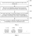
- Step S402: The receive end determines a physical layer transmission technology corresponding to the wireless communication data.
- In the present invention, when the receive end is user equipment and the transmit end is a base station, before step S401, the method further includes: receiving, by the receive end, downlink scheduling information that is corresponding to the wireless communication data and sent by the transmit end, where the downlink scheduling information carries the physical layer transmission technology identifier corresponding to the wireless communication data.
- In the present invention, step S402 is specifically:
determining, according to the physical layer transmission technology identifier carried in the downlink scheduling information, the physical layer transmission technology corresponding to the wireless communication data. - Optionally, when the receive end is a base station and the transmit end is user equipment, before step S401, the method further includes: allocating, by the receive end, different time-frequency resources for different physical layer transmission technologies; sending uplink scheduling information to the transmit end, where the uplink scheduling information carries time-frequency resource information corresponding to the physical layer transmission technology identifier, so that the transmit end determines a time-frequency resource corresponding to the physical layer transmission technology corresponding to the wireless communication data, and sends the wireless communication data to the receive end by using the determined time-frequency resource.
- Correspondingly, step S402 is specifically:
determining, according to the time-frequency resource used for the wireless communication data, the physical layer transmission technology corresponding to the wireless communication data. - Because the time-frequency resource is allocated by the base station, in a case in which the receive end is a base station, after receiving the wireless communication data, the base station may determine, according to the time-frequency resource used for the wireless communication data, the physical layer transmission technology used for the wireless communication data at the transmit end.
- In addition, the uplink scheduling information may further carry a correspondence between a data flow identifier and a physical layer transmission technology identifier. Then, before step S401, the method further includes: allocating a physical layer transmission technology for the data flow.
- Specifically, all transmit ends store mapping information between the data flow identifier and the physical layer transmission technology identifier. The mapping information includes the correspondence between the data flow identifier and the physical layer transmission technology identifier. The data flow identifier may be specifically an LCID corresponding to the data flow. The physical layer transmission technology includes: UFMC, FBMC, GFDM, BFDM, OFDM, or the like. The mapping information may be in a form shown in
FIG. 1 , or may be in another form, and no limitation is imposed in this embodiment of the present invention thereon. - A process in which the receive end sends the uplink scheduling information to the transmit end may be specifically: separately performing, by the receive end, processing, that is, scrambling, channel coding, and rate matching, on multiple uplink scheduling information, multiplexing all processed uplink scheduling information to generate an uplink scheduling information group, carrying the uplink scheduling information group over a downlink control channel, and sending the uplink scheduling information group to the transmit end; alternatively, multiplexing, by the receive end, the multiple uplink scheduling information to generate an uplink scheduling information group, performing processing, that is, scrambling, channel coding, and rate matching, on the uplink scheduling information group, carrying processed uplink scheduling information group over a downlink control channel, and sending the processed uplink scheduling information group to the transmit end.
- Step S403: The receive end obtains, by parsing the wireless communication data according to the determined physical layer transmission technology, a transport block corresponding to the wireless communication data.
- A PHY layer of the receive end obtains, by parsing the wireless communication data according to the determined physical layer transmission technology, a transport block corresponding to the wireless communication data.
- Step S404: The receive end acquires a data flow included in the transport block corresponding to the wireless communication data.
- A MAC sublayer of the receive end acquires the data flow from the transport block obtained by parsing the wireless communication data.
- By using the data transmission method provided in Embodiment 4 of the present invention, if the receive end is a base station, the base station may use different physical layer transmission technologies for multiple data flows of same user equipment, and if the receive end is user equipment, the user equipment may use the different physical layer transmission technologies for the multiple data flows, so that a spectrum resource is fully used and transmission efficiency is improved.
- For each of the foregoing embodiments, specifically, the foregoing mapping information between the data flow identifier and the physical layer transmission technology identifier may be established by the base station. When the base station establishes an uplink data connection to the user equipment, the base station allocates a physical layer transmission technology for a data flow according to a service proportion of each cell, so as to establish the mapping information between the data flow identifier and the physical layer transmission technology identifier. After the mapping information has been established, the base station carries the mapping information in configuration information and delivers the configuration information to the user equipment that is connected to the base station.
- Further, the base station may dynamically update the mapping information, and re-allocate the physical layer transmission technology for the data flow according to a change of the service proportion of each cell, so as to update the mapping information between the data flow identifier and the physical layer transmission technology identifier. After the mapping information is updated, the base station carries an updated correspondence between the data flow identifier and the physical layer transmission technology identifier in the uplink scheduling information and sends the uplink scheduling information to the user equipment, so that the user equipment updates the stored mapping information.
- If the base station uses fixed mapping information instead of dynamically updating the mapping information, only one type of physical layer transmission technology can be used for a same data flow in a data flow transmission process, and a multiplexing manner cannot be changed. If the base station can dynamically update the mapping information, different physical layer transmission technologies can be used the same data flow, and correspondingly, the multiplexing manner may also change, so that a spectrum resource may be used more fully and transmission efficiency is improved.
- A person skilled in the art may be further aware that, in combination with the examples described in the embodiments disclosed in this specification, units and algorithm steps may be implemented by electronic hardware, computer software, or a combination thereof. To clearly describe the interchangeability between the hardware and the software, the foregoing has generally described compositions and steps of each example according to functions. Whether the functions are performed by hardware or software depends on particular applications and design constraint conditions of the technical solutions. A person skilled in the art may use different methods to implement the described functions for each particular application, but it should not be considered that the implementation goes beyond the scope of the present invention.
- Steps of methods or algorithms described in the embodiments disclosed in this specification may be implemented by hardware, a software module executed by a processor, or a combination thereof. The software module may be configured in a random access memory (RAM), a memory, a read-only memory (ROM), an electrically programmable ROM, an electrically erasable programmable ROM, a register, a hard disk, a removable disk, a CD-ROM, or a storage medium in any other forms well-known in the art.
- In the foregoing specific embodiments, the objective, technical solutions, and benefits of the present invention are further described in detail. It should be understood that the foregoing descriptions are merely specific implementation manners of the present invention, but are not intended to limit the present invention.
Claims (12)
- A communications device, wherein the communications device is a user equipment and comprises: a memory (110), a processor (120), a communications interface (130), wherein:the memory (110) is configured to store mapping information between a data flow identifier and a physical layer transmission technology identifier, wherein a physical layer transmission technology corresponding to the physical layer transmission technology identifier comprises a waveform technology, wherein the wave technology is an universal filtered multicarrier technology, a filter bank multicarrier technology, a generalized frequency division multiplexing technology, a bi-orthogonal frequency division multiplexing technology, or an orthogonal frequency division multiplexing technology; andthe processor (120) is configured to: determine a to-be-scheduled data flow; determine, according to the mapping information and a data flow identifier of the data flow, a physical layer transmission technology identifier corresponding to the data flow; generate different transport blocks according to data flows corresponding to different physical layer transmission technology identifiers, wherein each physical layer transmission technology identifier is corresponding to one type of transport block; generate wireless communication data by performing processing, according to a physical layer transmission technology corresponding to the physical layer transmission technology identifier, on a transport block corresponding to the physical layer transmission technology identifier;and send the wireless communication data to a base station by using the communications interface (130);wherein the processor (120) is further configured to: before determining the to-be-scheduled data flow, receive, by using the communications interface (130), uplink scheduling information sent by the base station, where the uplink scheduling information carries time-frequency resource information corresponding to the physical layer transmission technology identifier;wherein the processor (120) is further configured to:determine, according to the time-frequency resource information corresponding to the physical layer transmission technology identifier, a time-frequency resource corresponding to the physical layer transmission technology corresponding to the wireless communication data; andsend the wireless communication data to the base station by using the time-frequency resource.
- The communications device according to claim 1, wherein the uplink scheduling information further carries a correspondence between the data flow identifier and the physical layer transmission technology identifier; and
the processor (120) is further configured to:
before the determining a to-be-scheduled data flow, update the mapping information according to the correspondence between the data flow identifier and the physical layer transmission technology identifier that is carried in the uplink scheduling information. - The communications device according to any claim 1 or 2, wherein
the data flow identifier is a logical channel identifier, LCID, at a media access control sublayer, a function entity number used at a Packet Data Convergence Protocol, PDCP, sublayer or a radio link control, RLC, sublayer, or a network transmission port number or a tunnel endpoint identifier that is used for identifying a data flow when the data flow is being implemented in the communications device; and
the physical layer transmission technology identifier comprises an identifier of a waveform technology. - A communications device, wherein the communications device is a base station and comprises a processor (210) and a communications interface (220); wherein
the processor (210) is configured to: receive, by using the communications interface (220), wireless communication data sent by a user equipment, UE; determine a physical layer transmission technology corresponding to the wireless communication data, wherein the physical layer transmission technology comprises a waveform technology, wherein the wave technology is an universal filtered multicarrier technology, a filter bank multicarrier technology, a generalized frequency division multiplexing technology, a bi-orthogonal frequency division multiplexing technology, or an orthogonal frequency division multiplexing technology; obtain, by parsing the wireless communication data according to the determined physical layer transmission technology, a transport block corresponding to the wireless communication data; and acquire a data flow comprised in the transport block corresponding to the wireless communication data;
wherein the processor (210) is further configured to: before receiving, by using the communications interface (220), the wireless communication data sent by the UE, allocate different time-frequency resources for different physical layer transmission technologies; send uplink scheduling information to the UE by using the communications interface (220), where the uplink scheduling information carries time-frequency resource information corresponding to a physical layer transmission technology identifier;
wherein the processor (210) is further configured to:
determine, according to the time-frequency resource used for the wireless communication data, the physical layer transmission technology corresponding to the wireless communication data. - The communications device according to claim 4, wherein the processor (210) is further configured to:before the sending uplink scheduling information to the UE by using the communications interface (220), allocate a physical layer transmission technology for the data flow, whereinthe uplink scheduling information further carries a correspondence between the data flow identifier and the physical layer transmission technology identifier.
- The communications device according to claim 4 or 5, wherein
the data flow identifier is a logical channel identifier, LCID, at a media access control sublayer, a function entity number used at a Packet Data Convergence Protocol, PDCP, sublayer or a radio link control, RLC, sublayer, or a network transmission port number or a tunnel endpoint identifier that is used for identifying a data flow when the data flow is being implemented in the communications device; and
the physical layer transmission technology identifier comprises an identifier of a waveform technology. - A data transmission method, wherein mapping information between a data flow identifier and a physical layer transmission technology identifier is stored at a user equipment, UE, the mapping information comprises: a correspondence between the data flow identifier and the physical layer transmission technology identifier, and the method comprises:determining (S301), by the UE, a to-be-scheduled data flow;determining (S302), by the UE, from the mapping information and according to a data flow identifier of the data flow, a physical layer transmission technology identifier corresponding to the data flow, wherein a physical layer transmission technology corresponding to the physical layer transmission technology identifier comprises a waveform technology, wherein the wave technology is an universal filtered multicarrier technology, a filter bank multicarrier technology, a generalized frequency division multiplexing technology, a bi-orthogonal frequency division multiplexing technology, or an orthogonal frequency division multiplexing technology;generating (S303), by the UE, different transport blocks according to data flows corresponding to different physical layer transmission technology identifiers, so as to send the data flow to a base station by using the transport block, wherein each physical layer transmission technology identifier is corresponding to one type of transport block;generating (S304), by the UE, wireless communication data by performing processing, according to a physical layer transmission technology corresponding to the physical layer transmission technology identifier, on a transport block corresponding to the physical layer transmission technology identifier; andsending (S305), by the UE, the wireless communication data to the base station;wherein the method further comprises: before determining (S301), by the UE, a to-be-scheduled data flow, the method further comprises:receiving, by the UE, uplink scheduling information sent by the base station,wherein the uplink scheduling information carries time-frequency resource information corresponding to the physical layer transmission technology identifier;
wherein sending, by the UE, the wireless communication data to the base station is specifically:determining, by the UE according to the time-frequency resource information corresponding to the physical layer transmission technology identifier, a time-frequency resource corresponding to the physical layer transmission technology corresponding to the wireless communication data; andsending, by the UE, the wireless communication data to the base station by using the time-frequency resource. - The method according to claim 7, wherein the uplink scheduling information further carries a correspondence between the data flow identifier and the physical layer transmission technology identifier; and
before determining (S301), by the UE, a to-be-scheduled data flow, the method further comprises:
updating, by the UE, the mapping information according to the correspondence between the data flow identifier and the physical layer transmission technology identifier that is carried in the uplink scheduling information. - The communications device according to claim 7 or 8, wherein
the data flow identifier is a logical channel identifier, LCID, at a media access control sublayer, a function entity number used at a Packet Data Convergence Protocol, PDCP, sublayer or a radio link control, RLC, sublayer, or a network transmission port number or a tunnel endpoint identifier that is used for identifying a data flow when the data flow is being implemented in the communications device; and
the physical layer transmission technology identifier comprises an identifier of a waveform technology. - A data transmission method, wherein the method comprises:receiving (S401), by a base station, wireless communication data sent by a user equipment, UE;determining (S402), by the base station, a physical layer transmission technology corresponding to the wireless communication data, wherein the physical layer transmission technology comprises a waveform technology, wherein the wave technology is an universal filtered multicarrier technology, a filter bank multicarrier technology, a generalized frequency division multiplexing technology, a bi-orthogonal frequency division multiplexing technology or an orthogonal frequency division multiplexing technology;obtaining (S403), by the base station by parsing the wireless communication data according to the determined physical layer transmission technology, a transport block corresponding to the wireless communication data; andacquiring (S404), by the base station, a data flow comprised in the transport block corresponding to the wireless communication data; andbefore receiving (S401), by the base station, the wireless communication data sent by the UE, the method further comprises:wherein determining, by the base station, a physical layer transmission technology corresponding to the wireless communication data is specifically:allocating, by the base station, different time-frequency resources for different physical layer transmission technologies;sending, by the base station, uplink scheduling information to the UE, wherein the uplink scheduling information carries time-frequency resource information corresponding to a physical layer transmission technology identifier;
determining, by the base station according to the time-frequency resource used for the wireless communication data, the physical layer transmission technology corresponding to the wireless communication data. - The method according to claim 10, wherein before sending, by the base station, uplink scheduling information to the UE, the method further comprises:allocating, by the base station, a physical layer transmission technology for the data flow; whereinthe uplink scheduling information further carries a correspondence between the data flow identifier and the physical layer transmission technology identifier.
- The communications method according to claim 10 or 11, wherein
the data flow identifier is a logical channel identifier, LCID, at a media access control sublayer, a function entity number used at a Packet Data Convergence Protocol, PDCP, sublayer or a radio link control, RLC, sublayer, or a network transmission port number or a tunnel endpoint identifier that is used for identifying a data flow when the data flow is being implemented in the communications device; and
the physical layer transmission technology identifier comprises an identifier of a waveform technology.
Applications Claiming Priority (2)
| Application Number | Priority Date | Filing Date | Title |
|---|---|---|---|
| PCT/CN2014/073121 WO2015135107A1 (en) | 2014-03-10 | 2014-03-10 | Data transmission method and communications device |
| PCT/CN2015/073576 WO2015135430A1 (en) | 2014-03-10 | 2015-03-03 | Data transmission method and communication device |
Publications (3)
| Publication Number | Publication Date |
|---|---|
| EP3119147A1 EP3119147A1 (en) | 2017-01-18 |
| EP3119147A4 EP3119147A4 (en) | 2017-02-22 |
| EP3119147B1 true EP3119147B1 (en) | 2020-05-06 |
Family
ID=54070752
Family Applications (1)
| Application Number | Title | Priority Date | Filing Date |
|---|---|---|---|
| EP15760830.8A Active EP3119147B1 (en) | 2014-03-10 | 2015-03-03 | Data transmission method and communication device |
Country Status (10)
| Country | Link |
|---|---|
| US (1) | US10257846B2 (en) |
| EP (1) | EP3119147B1 (en) |
| JP (1) | JP6343025B2 (en) |
| KR (1) | KR101886548B1 (en) |
| CN (1) | CN106538011B (en) |
| AU (1) | AU2015230528B2 (en) |
| BR (1) | BR112016020724B1 (en) |
| RU (1) | RU2650189C1 (en) |
| SG (1) | SG11201607538QA (en) |
| WO (2) | WO2015135107A1 (en) |
Families Citing this family (4)
| Publication number | Priority date | Publication date | Assignee | Title |
|---|---|---|---|---|
| WO2015135107A1 (en) | 2014-03-10 | 2015-09-17 | 华为技术有限公司 | Data transmission method and communications device |
| US9973364B2 (en) * | 2016-06-27 | 2018-05-15 | Intel IP Corporation | Generalized frequency division multiplexing (GFDM) frame strucutre for IEEE 802.11AY |
| CN107222293B (en) * | 2017-05-16 | 2020-03-20 | 北京邮电大学 | Information transmission method and device, electronic equipment and storage medium |
| CN113784370A (en) * | 2019-02-15 | 2021-12-10 | 华为技术有限公司 | Mapping method, node, communication device and storage medium |
Family Cites Families (27)
| Publication number | Priority date | Publication date | Assignee | Title |
|---|---|---|---|---|
| US6594246B1 (en) * | 1998-07-10 | 2003-07-15 | Malibu Networks, Inc. | IP-flow identification in a wireless point to multi-point transmission system |
| US7376879B2 (en) * | 2001-10-19 | 2008-05-20 | Interdigital Technology Corporation | MAC architecture in wireless communication systems supporting H-ARQ |
| CN1173500C (en) * | 2001-12-05 | 2004-10-27 | 华为技术有限公司 | High-speed down data packet accessing system support method to different service quality business |
| US20040254974A1 (en) * | 2003-06-11 | 2004-12-16 | Kamel Khamfallah | Methods and systems for assignment of user data blocks for transmission over a network |
| US7848236B2 (en) * | 2004-08-10 | 2010-12-07 | Nokia Corporation | Differentiation of quality classes to different PDUs with support for multiple terminals |
| CN1917411B (en) | 2005-08-16 | 2012-03-07 | 中兴通讯股份有限公司 | System and method for realization of accessing high speed down going packets in multiple carriers |
| CN101379747A (en) | 2005-12-29 | 2009-03-04 | 美商内数位科技公司 | Method and apparatus for selecting multiple transport formats and transmitting multiple transport blocks simultaneously with multiple H-ARQ processes |
| US8432794B2 (en) * | 2005-12-29 | 2013-04-30 | Interdigital Technology Corporation | Method and apparatus for selecting multiple transport formats and transmitting multiple transport blocks simultaneously with multiple H-ARQ processes |
| TWI427958B (en) * | 2005-12-29 | 2014-02-21 | Interdigital Tech Corp | Method and apparatus for selecting multiple transport formats and transmitting multiple transport blocks simultaneously with multiple h-arq processes |
| CN101179836B (en) * | 2006-11-08 | 2010-05-12 | 中兴通讯股份有限公司 | Method of decoding reinforced uplink physical channel of time-division synchronous code division multiple access system |
| CN101242345B (en) * | 2007-02-06 | 2011-09-21 | 中兴通讯股份有限公司 | Processing method and information format for high-speed downlink packet access channel status information feedback |
| CN101577694A (en) | 2008-05-09 | 2009-11-11 | 中兴通讯股份有限公司 | Method for indicating modulation mode of transmission blocks |
| CN101510791B (en) * | 2009-03-27 | 2012-04-18 | 北京天碁科技有限公司 | Transmitting device, modulation method and modulation device for time division radio communication system |
| CN101931880A (en) | 2009-06-19 | 2010-12-29 | 中兴通讯股份有限公司 | Resource distribution method for multimedia broadcast/multicast service (MBMS) dynamic multiplexing |
| CN101932102B (en) | 2009-06-19 | 2013-01-23 | 华为技术有限公司 | Service bearing mapping method and communication equipment thereof |
| CN102484885A (en) | 2009-08-21 | 2012-05-30 | 交互数字专利控股公司 | Method and apparatus for a multi-radio access technology layer for splitting downlink-uplink over different radio access technologies |
| CN102547848B (en) * | 2011-01-04 | 2015-08-05 | 华为技术有限公司 | A kind of method and apparatus processing business data flow |
| EP2667662A4 (en) | 2011-01-19 | 2016-05-18 | Fujitsu Ltd | Transmission device, transmission method and transmission system |
| WO2012137173A2 (en) | 2011-04-08 | 2012-10-11 | Renesas Mobile Corporation | Method and apparatus for enabling wireless connectivity |
| US20120259985A1 (en) | 2011-04-08 | 2012-10-11 | Renesas Mobile Corporation | Method and apparatus for enabling wireless connectivity |
| US9173228B2 (en) | 2011-06-28 | 2015-10-27 | Qualcomm Incorporated | Bluetooth packet scheduling rules for LTE coexistence |
| CN102869095B (en) * | 2011-07-06 | 2017-09-01 | 中兴通讯股份有限公司 | A kind of Notification Method of data transfer, system and network side equipment |
| WO2013009635A2 (en) * | 2011-07-08 | 2013-01-17 | Interdigital Patent Holdings, Inc. | Component carrier traffic mapping |
| US9629028B2 (en) * | 2012-03-16 | 2017-04-18 | Qualcomm Incorporated | System and method for heterogeneous carrier aggregation |
| US10038526B2 (en) * | 2013-02-15 | 2018-07-31 | Telefonaktiebolaget L M Ericsson (Publ) | Wireless device, a network node and methods therein for transmitting control information in a D2D communication |
| WO2015135107A1 (en) | 2014-03-10 | 2015-09-17 | 华为技术有限公司 | Data transmission method and communications device |
| CN106576017B (en) * | 2015-01-27 | 2019-09-24 | 瑞典爱立信有限公司 | For to the transmission device of receiving device transmission block, receiving device, control node and method therein |
-
2014
- 2014-03-10 WO PCT/CN2014/073121 patent/WO2015135107A1/en active Application Filing
-
2015
- 2015-03-03 JP JP2016556769A patent/JP6343025B2/en active Active
- 2015-03-03 CN CN201580013258.8A patent/CN106538011B/en active Active
- 2015-03-03 KR KR1020167027421A patent/KR101886548B1/en active IP Right Grant
- 2015-03-03 AU AU2015230528A patent/AU2015230528B2/en active Active
- 2015-03-03 WO PCT/CN2015/073576 patent/WO2015135430A1/en active Application Filing
- 2015-03-03 RU RU2016139372A patent/RU2650189C1/en active
- 2015-03-03 SG SG11201607538QA patent/SG11201607538QA/en unknown
- 2015-03-03 EP EP15760830.8A patent/EP3119147B1/en active Active
- 2015-03-03 BR BR112016020724-6A patent/BR112016020724B1/en active IP Right Grant
-
2016
- 2016-09-09 US US15/261,565 patent/US10257846B2/en active Active
Non-Patent Citations (1)
| Title |
|---|
| None * |
Also Published As
| Publication number | Publication date |
|---|---|
| JP6343025B2 (en) | 2018-06-13 |
| BR112016020724B1 (en) | 2023-11-07 |
| CN106538011A (en) | 2017-03-22 |
| WO2015135430A1 (en) | 2015-09-17 |
| JP2017513314A (en) | 2017-05-25 |
| US10257846B2 (en) | 2019-04-09 |
| WO2015135107A1 (en) | 2015-09-17 |
| SG11201607538QA (en) | 2016-10-28 |
| CN106538011B (en) | 2020-04-03 |
| KR20160129886A (en) | 2016-11-09 |
| EP3119147A4 (en) | 2017-02-22 |
| US20160381695A1 (en) | 2016-12-29 |
| AU2015230528B2 (en) | 2018-02-22 |
| RU2650189C1 (en) | 2018-04-11 |
| BR112016020724A2 (en) | 2017-08-15 |
| KR101886548B1 (en) | 2018-08-07 |
| EP3119147A1 (en) | 2017-01-18 |
| RU2016139372A (en) | 2018-04-11 |
| AU2015230528A1 (en) | 2016-09-29 |
Similar Documents
| Publication | Publication Date | Title |
|---|---|---|
| KR102104362B1 (en) | Signaling of frequency domain resource allocation | |
| US11398885B2 (en) | Signal transmission method and apparatus | |
| US10484984B2 (en) | Resource allocation method and apparatus | |
| WO2016146073A1 (en) | Ue supporting multi-user superposition, method and device of base station | |
| EP2509380A1 (en) | Method and device for distributing and scheduling wireless resources in orthogonal frequency division multiplexing system | |
| EP3627733B1 (en) | Communication method, network device and terminal device | |
| US10257846B2 (en) | Data transmission method and communications device | |
| EP3435554B1 (en) | Antenna port indication method and apparatus | |
| WO2011082696A1 (en) | Method and apparatus for notifying carrier indication information and acquiring carrier information | |
| CN103517439B (en) | Position processing method and base station, terminal | |
| CN110971349A (en) | Repeated transmission method, terminal and network side equipment | |
| US10631318B2 (en) | Resource division method and apparatus | |
| CN106817767B (en) | Multi-subband downlink resource allocation method, system and base station of wireless communication system | |
| WO2019010762A1 (en) | Data transmission method and device | |
| JP6517366B2 (en) | Downlink information receiving method and downlink information transmitting method, user equipment, and network device | |
| WO2020199609A1 (en) | Method and device for communication | |
| US20190261334A1 (en) | Transmission control method, apparatus, and system, and storage medium | |
| WO2018228456A1 (en) | Method for transmitting control information, terminal, network side device, and communication system | |
| CN107534604A (en) | A kind of data processing method and device | |
| WO2018094712A1 (en) | Wireless access network configuration method, apparatus and system | |
| CN103249161B (en) | Resource scheduling method and device | |
| WO2019137175A1 (en) | Method, apparatus and device for resource set position indication and rate matching | |
| CN115428532A (en) | Method and node for efficient MAC CE design for indicating mapping between path loss reference and multiple SRIs | |
| WO2018233640A1 (en) | Method and apparatus for indicating and determining slot structure |
Legal Events
| Date | Code | Title | Description |
|---|---|---|---|
| STAA | Information on the status of an ep patent application or granted ep patent |
Free format text: STATUS: THE INTERNATIONAL PUBLICATION HAS BEEN MADE |
|
| PUAI | Public reference made under article 153(3) epc to a published international application that has entered the european phase |
Free format text: ORIGINAL CODE: 0009012 |
|
| STAA | Information on the status of an ep patent application or granted ep patent |
Free format text: STATUS: REQUEST FOR EXAMINATION WAS MADE |
|
| 17P | Request for examination filed |
Effective date: 20160920 |
|
| AK | Designated contracting states |
Kind code of ref document: A1 Designated state(s): AL AT BE BG CH CY CZ DE DK EE ES FI FR GB GR HR HU IE IS IT LI LT LU LV MC MK MT NL NO PL PT RO RS SE SI SK SM TR |
|
| AX | Request for extension of the european patent |
Extension state: BA ME |
|
| A4 | Supplementary search report drawn up and despatched |
Effective date: 20170120 |
|
| RIC1 | Information provided on ipc code assigned before grant |
Ipc: H04W 72/12 20090101AFI20170116BHEP Ipc: H04W 76/02 20090101ALN20170116BHEP |
|
| DAV | Request for validation of the european patent (deleted) | ||
| DAX | Request for extension of the european patent (deleted) | ||
| STAA | Information on the status of an ep patent application or granted ep patent |
Free format text: STATUS: EXAMINATION IS IN PROGRESS |
|
| 17Q | First examination report despatched |
Effective date: 20180619 |
|
| REG | Reference to a national code |
Ref country code: DE Ref legal event code: R079 Ref document number: 602015052253 Country of ref document: DE Free format text: PREVIOUS MAIN CLASS: H04W0072040000 Ipc: H04W0076110000 |
|
| GRAP | Despatch of communication of intention to grant a patent |
Free format text: ORIGINAL CODE: EPIDOSNIGR1 |
|
| STAA | Information on the status of an ep patent application or granted ep patent |
Free format text: STATUS: GRANT OF PATENT IS INTENDED |
|
| RIC1 | Information provided on ipc code assigned before grant |
Ipc: H04W 76/11 20180101AFI20190927BHEP Ipc: H04W 76/16 20180101ALN20190927BHEP |
|
| INTG | Intention to grant announced |
Effective date: 20191105 |
|
| GRAS | Grant fee paid |
Free format text: ORIGINAL CODE: EPIDOSNIGR3 |
|
| GRAA | (expected) grant |
Free format text: ORIGINAL CODE: 0009210 |
|
| STAA | Information on the status of an ep patent application or granted ep patent |
Free format text: STATUS: THE PATENT HAS BEEN GRANTED |
|
| AK | Designated contracting states |
Kind code of ref document: B1 Designated state(s): AL AT BE BG CH CY CZ DE DK EE ES FI FR GB GR HR HU IE IS IT LI LT LU LV MC MK MT NL NO PL PT RO RS SE SI SK SM TR |
|
| REG | Reference to a national code |
Ref country code: GB Ref legal event code: FG4D |
|
| REG | Reference to a national code |
Ref country code: CH Ref legal event code: EP Ref country code: AT Ref legal event code: REF Ref document number: 1268907 Country of ref document: AT Kind code of ref document: T Effective date: 20200515 |
|
| REG | Reference to a national code |
Ref country code: IE Ref legal event code: FG4D |
|
| REG | Reference to a national code |
Ref country code: DE Ref legal event code: R096 Ref document number: 602015052253 Country of ref document: DE |
|
| REG | Reference to a national code |
Ref country code: LT Ref legal event code: MG4D |
|
| REG | Reference to a national code |
Ref country code: NL Ref legal event code: MP Effective date: 20200506 |
|
| PG25 | Lapsed in a contracting state [announced via postgrant information from national office to epo] |
Ref country code: SE Free format text: LAPSE BECAUSE OF FAILURE TO SUBMIT A TRANSLATION OF THE DESCRIPTION OR TO PAY THE FEE WITHIN THE PRESCRIBED TIME-LIMIT Effective date: 20200506 Ref country code: LT Free format text: LAPSE BECAUSE OF FAILURE TO SUBMIT A TRANSLATION OF THE DESCRIPTION OR TO PAY THE FEE WITHIN THE PRESCRIBED TIME-LIMIT Effective date: 20200506 Ref country code: GR Free format text: LAPSE BECAUSE OF FAILURE TO SUBMIT A TRANSLATION OF THE DESCRIPTION OR TO PAY THE FEE WITHIN THE PRESCRIBED TIME-LIMIT Effective date: 20200807 Ref country code: NO Free format text: LAPSE BECAUSE OF FAILURE TO SUBMIT A TRANSLATION OF THE DESCRIPTION OR TO PAY THE FEE WITHIN THE PRESCRIBED TIME-LIMIT Effective date: 20200806 Ref country code: IS Free format text: LAPSE BECAUSE OF FAILURE TO SUBMIT A TRANSLATION OF THE DESCRIPTION OR TO PAY THE FEE WITHIN THE PRESCRIBED TIME-LIMIT Effective date: 20200906 Ref country code: PT Free format text: LAPSE BECAUSE OF FAILURE TO SUBMIT A TRANSLATION OF THE DESCRIPTION OR TO PAY THE FEE WITHIN THE PRESCRIBED TIME-LIMIT Effective date: 20200907 Ref country code: FI Free format text: LAPSE BECAUSE OF FAILURE TO SUBMIT A TRANSLATION OF THE DESCRIPTION OR TO PAY THE FEE WITHIN THE PRESCRIBED TIME-LIMIT Effective date: 20200506 |
|
| PG25 | Lapsed in a contracting state [announced via postgrant information from national office to epo] |
Ref country code: LV Free format text: LAPSE BECAUSE OF FAILURE TO SUBMIT A TRANSLATION OF THE DESCRIPTION OR TO PAY THE FEE WITHIN THE PRESCRIBED TIME-LIMIT Effective date: 20200506 Ref country code: RS Free format text: LAPSE BECAUSE OF FAILURE TO SUBMIT A TRANSLATION OF THE DESCRIPTION OR TO PAY THE FEE WITHIN THE PRESCRIBED TIME-LIMIT Effective date: 20200506 Ref country code: HR Free format text: LAPSE BECAUSE OF FAILURE TO SUBMIT A TRANSLATION OF THE DESCRIPTION OR TO PAY THE FEE WITHIN THE PRESCRIBED TIME-LIMIT Effective date: 20200506 Ref country code: BG Free format text: LAPSE BECAUSE OF FAILURE TO SUBMIT A TRANSLATION OF THE DESCRIPTION OR TO PAY THE FEE WITHIN THE PRESCRIBED TIME-LIMIT Effective date: 20200806 |
|
| REG | Reference to a national code |
Ref country code: AT Ref legal event code: MK05 Ref document number: 1268907 Country of ref document: AT Kind code of ref document: T Effective date: 20200506 |
|
| PG25 | Lapsed in a contracting state [announced via postgrant information from national office to epo] |
Ref country code: NL Free format text: LAPSE BECAUSE OF FAILURE TO SUBMIT A TRANSLATION OF THE DESCRIPTION OR TO PAY THE FEE WITHIN THE PRESCRIBED TIME-LIMIT Effective date: 20200506 Ref country code: AL Free format text: LAPSE BECAUSE OF FAILURE TO SUBMIT A TRANSLATION OF THE DESCRIPTION OR TO PAY THE FEE WITHIN THE PRESCRIBED TIME-LIMIT Effective date: 20200506 |
|
| PG25 | Lapsed in a contracting state [announced via postgrant information from national office to epo] |
Ref country code: CZ Free format text: LAPSE BECAUSE OF FAILURE TO SUBMIT A TRANSLATION OF THE DESCRIPTION OR TO PAY THE FEE WITHIN THE PRESCRIBED TIME-LIMIT Effective date: 20200506 Ref country code: IT Free format text: LAPSE BECAUSE OF FAILURE TO SUBMIT A TRANSLATION OF THE DESCRIPTION OR TO PAY THE FEE WITHIN THE PRESCRIBED TIME-LIMIT Effective date: 20200506 Ref country code: RO Free format text: LAPSE BECAUSE OF FAILURE TO SUBMIT A TRANSLATION OF THE DESCRIPTION OR TO PAY THE FEE WITHIN THE PRESCRIBED TIME-LIMIT Effective date: 20200506 Ref country code: DK Free format text: LAPSE BECAUSE OF FAILURE TO SUBMIT A TRANSLATION OF THE DESCRIPTION OR TO PAY THE FEE WITHIN THE PRESCRIBED TIME-LIMIT Effective date: 20200506 Ref country code: AT Free format text: LAPSE BECAUSE OF FAILURE TO SUBMIT A TRANSLATION OF THE DESCRIPTION OR TO PAY THE FEE WITHIN THE PRESCRIBED TIME-LIMIT Effective date: 20200506 Ref country code: ES Free format text: LAPSE BECAUSE OF FAILURE TO SUBMIT A TRANSLATION OF THE DESCRIPTION OR TO PAY THE FEE WITHIN THE PRESCRIBED TIME-LIMIT Effective date: 20200506 Ref country code: SM Free format text: LAPSE BECAUSE OF FAILURE TO SUBMIT A TRANSLATION OF THE DESCRIPTION OR TO PAY THE FEE WITHIN THE PRESCRIBED TIME-LIMIT Effective date: 20200506 Ref country code: EE Free format text: LAPSE BECAUSE OF FAILURE TO SUBMIT A TRANSLATION OF THE DESCRIPTION OR TO PAY THE FEE WITHIN THE PRESCRIBED TIME-LIMIT Effective date: 20200506 |
|
| REG | Reference to a national code |
Ref country code: DE Ref legal event code: R097 Ref document number: 602015052253 Country of ref document: DE |
|
| PG25 | Lapsed in a contracting state [announced via postgrant information from national office to epo] |
Ref country code: PL Free format text: LAPSE BECAUSE OF FAILURE TO SUBMIT A TRANSLATION OF THE DESCRIPTION OR TO PAY THE FEE WITHIN THE PRESCRIBED TIME-LIMIT Effective date: 20200506 Ref country code: SK Free format text: LAPSE BECAUSE OF FAILURE TO SUBMIT A TRANSLATION OF THE DESCRIPTION OR TO PAY THE FEE WITHIN THE PRESCRIBED TIME-LIMIT Effective date: 20200506 |
|
| PLBE | No opposition filed within time limit |
Free format text: ORIGINAL CODE: 0009261 |
|
| STAA | Information on the status of an ep patent application or granted ep patent |
Free format text: STATUS: NO OPPOSITION FILED WITHIN TIME LIMIT |
|
| 26N | No opposition filed |
Effective date: 20210209 |
|
| PG25 | Lapsed in a contracting state [announced via postgrant information from national office to epo] |
Ref country code: SI Free format text: LAPSE BECAUSE OF FAILURE TO SUBMIT A TRANSLATION OF THE DESCRIPTION OR TO PAY THE FEE WITHIN THE PRESCRIBED TIME-LIMIT Effective date: 20200506 |
|
| REG | Reference to a national code |
Ref country code: DE Ref legal event code: R119 Ref document number: 602015052253 Country of ref document: DE |
|
| PG25 | Lapsed in a contracting state [announced via postgrant information from national office to epo] |
Ref country code: MC Free format text: LAPSE BECAUSE OF FAILURE TO SUBMIT A TRANSLATION OF THE DESCRIPTION OR TO PAY THE FEE WITHIN THE PRESCRIBED TIME-LIMIT Effective date: 20200506 |
|
| REG | Reference to a national code |
Ref country code: CH Ref legal event code: PL |
|
| REG | Reference to a national code |
Ref country code: BE Ref legal event code: MM Effective date: 20210331 |
|
| PG25 | Lapsed in a contracting state [announced via postgrant information from national office to epo] |
Ref country code: LI Free format text: LAPSE BECAUSE OF NON-PAYMENT OF DUE FEES Effective date: 20210331 Ref country code: LU Free format text: LAPSE BECAUSE OF NON-PAYMENT OF DUE FEES Effective date: 20210303 Ref country code: CH Free format text: LAPSE BECAUSE OF NON-PAYMENT OF DUE FEES Effective date: 20210331 Ref country code: IE Free format text: LAPSE BECAUSE OF NON-PAYMENT OF DUE FEES Effective date: 20210303 Ref country code: FR Free format text: LAPSE BECAUSE OF NON-PAYMENT OF DUE FEES Effective date: 20210331 Ref country code: DE Free format text: LAPSE BECAUSE OF NON-PAYMENT OF DUE FEES Effective date: 20211001 |
|
| PG25 | Lapsed in a contracting state [announced via postgrant information from national office to epo] |
Ref country code: BE Free format text: LAPSE BECAUSE OF NON-PAYMENT OF DUE FEES Effective date: 20210331 |
|
| PG25 | Lapsed in a contracting state [announced via postgrant information from national office to epo] |
Ref country code: HU Free format text: LAPSE BECAUSE OF FAILURE TO SUBMIT A TRANSLATION OF THE DESCRIPTION OR TO PAY THE FEE WITHIN THE PRESCRIBED TIME-LIMIT; INVALID AB INITIO Effective date: 20150303 |
|
| PGFP | Annual fee paid to national office [announced via postgrant information from national office to epo] |
Ref country code: GB Payment date: 20230202 Year of fee payment: 9 |
|
| P01 | Opt-out of the competence of the unified patent court (upc) registered |
Effective date: 20230524 |
|
| PG25 | Lapsed in a contracting state [announced via postgrant information from national office to epo] |
Ref country code: CY Free format text: LAPSE BECAUSE OF FAILURE TO SUBMIT A TRANSLATION OF THE DESCRIPTION OR TO PAY THE FEE WITHIN THE PRESCRIBED TIME-LIMIT Effective date: 20200506 |