EP3119121B1 - Reference signal detection method, receiving method, user equipment and base station - Google Patents
Reference signal detection method, receiving method, user equipment and base station Download PDFInfo
- Publication number
- EP3119121B1 EP3119121B1 EP14887781.4A EP14887781A EP3119121B1 EP 3119121 B1 EP3119121 B1 EP 3119121B1 EP 14887781 A EP14887781 A EP 14887781A EP 3119121 B1 EP3119121 B1 EP 3119121B1
- Authority
- EP
- European Patent Office
- Prior art keywords
- frequency resource
- time
- partial
- resource
- frequency
- Prior art date
- Legal status (The legal status is an assumption and is not a legal conclusion. Google has not performed a legal analysis and makes no representation as to the accuracy of the status listed.)
- Active
Links
- 238000000034 method Methods 0.000 title claims description 36
- 238000001514 detection method Methods 0.000 title claims description 35
- 238000005259 measurement Methods 0.000 description 67
- 238000000794 confocal Raman spectroscopy Methods 0.000 description 29
- 238000011500 cytoreductive surgery Methods 0.000 description 29
- 230000011664 signaling Effects 0.000 description 23
- 238000010586 diagram Methods 0.000 description 21
- 201000000913 Duane retraction syndrome Diseases 0.000 description 19
- 238000004891 communication Methods 0.000 description 19
- 238000000162 direct recoil spectroscopy Methods 0.000 description 19
- 238000013461 design Methods 0.000 description 12
- 108010076504 Protein Sorting Signals Proteins 0.000 description 8
- 238000000926 separation method Methods 0.000 description 7
- 230000006870 function Effects 0.000 description 6
- 230000008569 process Effects 0.000 description 6
- 238000001228 spectrum Methods 0.000 description 5
- 230000007774 longterm Effects 0.000 description 4
- 238000007726 management method Methods 0.000 description 4
- 238000012545 processing Methods 0.000 description 4
- 230000005540 biological transmission Effects 0.000 description 3
- 230000008878 coupling Effects 0.000 description 3
- 238000010168 coupling process Methods 0.000 description 3
- 238000005859 coupling reaction Methods 0.000 description 3
- 238000005516 engineering process Methods 0.000 description 3
- 230000001413 cellular effect Effects 0.000 description 2
- 239000013256 coordination polymer Substances 0.000 description 2
- 125000004122 cyclic group Chemical group 0.000 description 2
- PCHJSUWPFVWCPO-UHFFFAOYSA-N gold Chemical group [Au] PCHJSUWPFVWCPO-UHFFFAOYSA-N 0.000 description 2
- 230000000977 initiatory effect Effects 0.000 description 2
- 238000010295 mobile communication Methods 0.000 description 2
- 230000003287 optical effect Effects 0.000 description 2
- 230000008901 benefit Effects 0.000 description 1
- 238000004422 calculation algorithm Methods 0.000 description 1
- 238000004364 calculation method Methods 0.000 description 1
- 238000004590 computer program Methods 0.000 description 1
- 238000012217 deletion Methods 0.000 description 1
- 230000037430 deletion Effects 0.000 description 1
- 230000001419 dependent effect Effects 0.000 description 1
- 230000000694 effects Effects 0.000 description 1
- 230000005611 electricity Effects 0.000 description 1
- 230000007246 mechanism Effects 0.000 description 1
- 238000013468 resource allocation Methods 0.000 description 1
- 238000012772 sequence design Methods 0.000 description 1
Images


Classifications
-
- H—ELECTRICITY
- H04—ELECTRIC COMMUNICATION TECHNIQUE
- H04L—TRANSMISSION OF DIGITAL INFORMATION, e.g. TELEGRAPHIC COMMUNICATION
- H04L5/00—Arrangements affording multiple use of the transmission path
- H04L5/003—Arrangements for allocating sub-channels of the transmission path
- H04L5/0048—Allocation of pilot signals, i.e. of signals known to the receiver
-
- H—ELECTRICITY
- H04—ELECTRIC COMMUNICATION TECHNIQUE
- H04B—TRANSMISSION
- H04B17/00—Monitoring; Testing
- H04B17/30—Monitoring; Testing of propagation channels
- H04B17/309—Measuring or estimating channel quality parameters
- H04B17/318—Received signal strength
-
- H—ELECTRICITY
- H04—ELECTRIC COMMUNICATION TECHNIQUE
- H04L—TRANSMISSION OF DIGITAL INFORMATION, e.g. TELEGRAPHIC COMMUNICATION
- H04L1/00—Arrangements for detecting or preventing errors in the information received
- H04L1/0001—Systems modifying transmission characteristics according to link quality, e.g. power backoff
- H04L1/0036—Systems modifying transmission characteristics according to link quality, e.g. power backoff arrangements specific to the receiver
- H04L1/0038—Blind format detection
-
- H—ELECTRICITY
- H04—ELECTRIC COMMUNICATION TECHNIQUE
- H04L—TRANSMISSION OF DIGITAL INFORMATION, e.g. TELEGRAPHIC COMMUNICATION
- H04L5/00—Arrangements affording multiple use of the transmission path
- H04L5/0001—Arrangements for dividing the transmission path
- H04L5/0003—Two-dimensional division
- H04L5/0005—Time-frequency
- H04L5/0007—Time-frequency the frequencies being orthogonal, e.g. OFDM(A), DMT
-
- H—ELECTRICITY
- H04—ELECTRIC COMMUNICATION TECHNIQUE
- H04L—TRANSMISSION OF DIGITAL INFORMATION, e.g. TELEGRAPHIC COMMUNICATION
- H04L5/00—Arrangements affording multiple use of the transmission path
- H04L5/0091—Signaling for the administration of the divided path
- H04L5/0092—Indication of how the channel is divided
-
- H—ELECTRICITY
- H04—ELECTRIC COMMUNICATION TECHNIQUE
- H04W—WIRELESS COMMUNICATION NETWORKS
- H04W48/00—Access restriction; Network selection; Access point selection
- H04W48/16—Discovering, processing access restriction or access information
-
- H—ELECTRICITY
- H04—ELECTRIC COMMUNICATION TECHNIQUE
- H04L—TRANSMISSION OF DIGITAL INFORMATION, e.g. TELEGRAPHIC COMMUNICATION
- H04L5/00—Arrangements affording multiple use of the transmission path
- H04L5/003—Arrangements for allocating sub-channels of the transmission path
- H04L5/0037—Inter-user or inter-terminal allocation
-
- H—ELECTRICITY
- H04—ELECTRIC COMMUNICATION TECHNIQUE
- H04L—TRANSMISSION OF DIGITAL INFORMATION, e.g. TELEGRAPHIC COMMUNICATION
- H04L5/00—Arrangements affording multiple use of the transmission path
- H04L5/0091—Signaling for the administration of the divided path
- H04L5/0096—Indication of changes in allocation
- H04L5/0098—Signalling of the activation or deactivation of component carriers, subcarriers or frequency bands
Definitions
- the present invention relates to the field of communications technologies, and in particular, to a reference signal detection method and receiving method, user equipment, and a base station.
- a Long Term Evolution (LTE, Long Term Evolution) system is based on an orthogonal frequency division multiplexing (OFDM, Orthogonal Frequency Division Multiplexing) technology, and time-frequency resources of the LTE system are classified into an OFDM symbol in a time domain dimension and an OFDM subcarrier in a frequency domain dimension.
- OFDM Orthogonal Frequency Division Multiplexing
- a smallest resource granularity is referred to as a resource element (RE, Resource Element), that is, a time and frequency grid representing an OFDM symbol in a time domain and an OFDM subcarrier in a frequency domain.
- prior art document R1-141485, 3GPP TSG_RAN WG1 #76bis refers to a discussion of enhancements for small cell discovery and RRM measurements.
- prior art document R1-141291, 3GPP TSG-RAN WG1#76bis refers to a discussion on a discovery reference signal design.
- Service transmission in the LTE system is based on base station scheduling.
- a base station sends a control channel.
- the control channel may carry scheduling information of a data channel of uplink or downlink data.
- the scheduling information includes control information such as resource allocation information and an encoding adjustment manner.
- User equipment UE, User Equipment
- the base station schedules the UE by using a resource block (RB, Resource Block) as a granularity.
- RB Resource Block
- One resource block occupies a length of one subframe in a time domain and occupies a width of 12 OFDM subcarriers in a frequency domain.
- CP common cyclic prefix
- one subframe includes 14 OFDM symbols.
- one subframe includes 12 OFDM symbols.
- the UE needs to perform synchronization, channel state measurement, and radio resource management measurement according to a reference signal sent by the base station.
- Synchronization is further classified into initial coarse synchronization and fine time-frequency tracking synchronization.
- the initial coarse synchronization is implemented according to a primary synchronization signal (PSS, Primary Synchronization Signal) and a secondary synchronization signal (SSS, Secondary Synchronization Signal) that are sent by the base station.
- PSS Primary Synchronization Signal
- SSS Secondary Synchronization Signal
- the fine time-frequency tracking synchronization is implemented by using a cell-specific reference signal (CRS, Cell-specific Reference Signal) sent by the base station.
- CRS Cell-specific Reference Signal
- the channel state measurement includes channel measurement and interference measurement, and measurement may be performed based on a CRS or a channel state information reference signal (CS1-RS, Channel State Information-Reference Signal).
- CS1-RS Channel State Information-Reference Signal
- the radio resource management measurement includes measurement of reference signal received power (RSRP, Reference Signal Received Power), reference signal received quality (RSRQ, Reference Signal Received Quality), a received signal strength indicator (RSSI, Received Signal Strength Indicator), or the like, and is currently implemented by using a CRS or an RCRS.
- the RSRP indicates average power, which is included in a CRS resource element of a target measured cell, of CRSs sent by the measured cell.
- the RSSI indicates average power of all signals in OFDM symbols in which the CRSs of the measured cell are located, including signal power of a current cell, signal power of an intra-frequency neighboring cell, signal power leaked from an inter-frequency band to a current frequency band, and average power of all signals such as a thermal noise signal.
- the RSRQ is obtained according to a ratio of the RSRP to the RSSI, and RSRP measurement and RSSI measurement that determine the RSRQ are performed in OFDM symbols, in which CRSs are located, in a same resource block.
- the RRM measurement may further include signal to interference plus noise ratio (SINR, Signal to Interference plus Noise Ratio) measurement.
- SINR Signal to Interference plus Noise Ratio
- a signal to interference plus noise ratio may be determined by using a ratio of the RSRP and interference measurement of a neighboring cell.
- a CRS is sent in each subframe in the LTE system.
- CCT New Carrier Type
- RCRS Reduced CRS
- a subsequent evolved LTE system has a relatively high requirement on power and efficiency of a base station, and in future network topology evolution, an operator deploys a large quantity of heterogeneous networks.
- a large quantity of small cells are deployed in a range of a macro cell, where the macro cell mainly provides coverage and a real-time data service, a small cell mainly provides a high-speed data service, and the macro cell and the small cell may be deployed on a same frequency or different frequencies, but a deployment scenario of different frequencies predominates.
- the foregoing reference signals such as the PSS, the SSS, the CRS/RCRS, and the CSI-RS also need to be sent.
- Sending of these reference signals having relatively short sending periods may cause severe inter-cell interference.
- network density may result in that no UE is served in a range of a large quantity of small cells, that is, within a particular period of time, UE in a range of only some small cells of all the foregoing small cells is served.
- a potential solution is to turn off these small cells that serve no UE, that is, none of a PSS, an SSS, a CRS/RCRS, a CSI-RS, a control channel, and a data channel is sent, so as to completely turn off the small cells, and achieve an effect of energy saving and reducing inter-cell interference, enabling a small cell that is serving UE to provide a more highly efficient service.
- the UE cannot promptly discover or detect deployment of the small cell and perform radio resource management (RRM, Radio Resource Management) measurement on the small cell.
- RRM Radio Resource Management
- a network side does not know when to turn on the small cell, and cannot determine, according to a result, reported by the UE, of measurement performed on the small cell, whether to turn on the small cell and whether to configure the cell for the UE.
- the present invention provides a reference signal detection method and receiving method, user equipment, and a base station, which can improve cell discovery and measurement performance.
- user equipment including: a determining unit, configured to determine configuration information of a reference signal, where the configuration information includes information about a first candidate time-frequency resource and information about a second candidate time-frequency resource, where the first candidate time-frequency resource includes a first partial time-frequency resource and a second partial time-frequency resource, the first partial time-frequency resource is a first partial resource in a first mute time-frequency resource, and the second partial time-frequency resource is a second partial resource in a second mute time-frequency resource; the second candidate time-frequency resource includes a third partial time-frequency resource and a fourth partial time-frequency resource, the third partial time-frequency resource is a third partial resource in the first mute time-frequency resource, and the fourth partial time-frequency resource is a fourth partial resource in the second mute time-frequency resource; and the first partial resource, the second partial resource, the third partial resource, and the fourth partial resource do not overlap one another; and a detection unit, configured to detect the reference signal according to the configuration information
- the detection unit is specifically configured to: determine reference signal received power RSRP of a current cell according to receive power of the reference signal detected on the first partial time-frequency resource, or determine RSRP of a current cell according to receive power of the reference signal detected on the first partial time-frequency resource and the second partial time-frequency resource; determine a received signal strength indicator RSSI of the current cell according to total receive power on the second partial time-frequency resource or a first resource to which the second partial time-frequency resource belongs, where the first resource is any one of an orthogonal frequency division multiplexing OFDM symbol, a timeslot, a subframe, or a subframe set; and determine reference signal received quality RSRQ of the current cell according to the RSRP and the RSSI.
- the configuration information determined by the determining unit further includes information about a third candidate time-frequency resource, where the third candidate time-frequency resource includes a fifth partial time-frequency resource and a sixth partial time-frequency resource, the fifth partial time-frequency resource and the first partial resource overlap completely, the sixth partial time-frequency resource and the second partial resource do not overlap, the sixth partial time-frequency resource and the third partial resource do not overlap, the sixth partial time-frequency resource and the fourth partial resource do not overlap, and the sixth partial time-frequency resource is a partial resource in a third mute time-frequency resource.
- the first partial time-frequency resource and the second partial time-frequency resource are at different moments, and the third partial time-frequency resource and the fourth partial time-frequency resource are at different moments; or the first partial time-frequency resource and the second partial time-frequency resource are at a same moment, and the third partial time-frequency resource and the fourth partial time-frequency resource are at a same moment and a frequency domain subcarrier of the third partial time-frequency resource and a frequency domain subcarrier of the fourth partial time-frequency resource are adjacent.
- the configuration information determined by the determining unit further includes information about at least one candidate sequence, where the candidate sequence includes a frequency domain scrambling code and/or a time domain orthogonal code.
- a base station including: a determining unit, configured to determine a sending resource of a reference signal, where the sending resource of the reference signal is selected from configuration information of the reference signal, and the configuration information includes information about a first candidate time-frequency resource and information about a second candidate time-frequency resource, where the first candidate time-frequency resource includes a first partial time-frequency resource and a second partial time-frequency resource, the first partial time-frequency resource is a first partial resource in a first mute time-frequency resource, and the second partial time-frequency resource is a second partial resource in a second mute time-frequency resource; the second candidate time-frequency resource includes a third partial time-frequency resource and a fourth partial time-frequency resource, the third partial time-frequency resource is a third partial resource in the first mute time-frequency resource, and the fourth partial time-frequency resource is a fourth partial resource in the second mute time-frequency resource; and the first partial resource, the second partial resource, the third partial resource, and the fourth partial resource do
- the configuration information further includes information about a third candidate time-frequency resource, where the third candidate time-frequency resource includes a fifth partial time-frequency resource and a sixth partial time-frequency resource, the fifth partial time-frequency resource and the first partial resource overlap completely, the sixth partial time-frequency resource and the second partial resource do not overlap, the sixth partial time-frequency resource and the third partial resource do not overlap, the sixth partial time-frequency resource and the fourth partial resource do not overlap, and the sixth partial time-frequency resource is a partial resource in a third mute time-frequency resource.
- the first partial time-frequency resource and the second partial time-frequency resource are at different moments, and the third partial time-frequency resource and the fourth partial time-frequency resource are at different moments; or the first partial time-frequency resource and the second partial time-frequency resource are at a same moment, and the third partial time-frequency resource and the fourth partial time-frequency resource are at a same moment and a frequency domain subcarrier of the third partial time-frequency resource and a frequency domain subcarrier of the fourth partial time-frequency resource are adjacent.
- a reference signal detection method including: determining configuration information of a reference signal, where the configuration information includes information about a first candidate time-frequency resource and information about a second candidate time-frequency resource, where the first candidate time-frequency resource includes a first partial time-frequency resource and a second partial time-frequency resource, the first partial time-frequency resource is a first partial resource in a first mute time-frequency resource, and the second partial time-frequency resource is a second partial resource in a second mute time-frequency resource; the second candidate time-frequency resource includes a third partial time-frequency resource and a fourth partial time-frequency resource, the third partial time-frequency resource is a third partial resource in the first mute time-frequency resource, and the fourth partial time-frequency resource is a fourth partial resource in the second mute time-frequency resource; and the first partial resource, the second partial resource, the third partial resource, and the fourth partial resource do not overlap one another; and detecting the reference signal according to the configuration information, characterized in that the first candidate time
- the detecting the reference signal according to the configuration information includes: determining reference signal received power RSRP of a current cell according to receive power of the reference signal detected on the first partial time-frequency resource, or determining RSRP of a current cell according to receive power of the reference signal detected on the first partial time-frequency resource and the second partial time-frequency resource; determining a received signal strength indicator RSSI of the current cell according to total receive power on the second partial time-frequency resource or a first resource to which the second partial time-frequency resource belongs, where the first resource is any one of an orthogonal frequency division multiplexing OFDM symbol, a timeslot, a subframe, or a subframe set; and determining reference signal received quality RSRQ of the current cell according to the RSRP and the RSSI.
- the configuration information further includes information about a third candidate time-frequency resource, where the third candidate time-frequency resource includes a fifth partial time-frequency resource and a sixth partial time-frequency resource, the fifth partial time-frequency resource and the first partial resource overlap completely, the sixth partial time-frequency resource and the second partial resource do not overlap, the sixth partial time-frequency resource and the third partial resource do not overlap, the sixth partial time-frequency resource and the fourth partial resource do not overlap, and the sixth partial time-frequency resource is a partial resource in a third mute time-frequency resource.
- the first partial time-frequency resource and the second partial time-frequency resource are at different moments, and the third partial time-frequency resource and the fourth partial time-frequency resource are at different moments; or the first partial time-frequency resource and the second partial time-frequency resource are at a same moment, and the third partial time-frequency resource and the fourth partial time-frequency resource are at a same moment and a frequency domain subcarrier of the third partial time-frequency resource and a frequency domain subcarrier of the fourth partial time-frequency resource are adjacent.
- a reference signal sending method including: determining a sending resource of a reference signal, where the sending resource of the reference signal is selected from configuration information of the reference signal, and the configuration information includes information about a first candidate time-frequency resource and information about a second candidate time-frequency resource, where the first candidate time-frequency resource includes a first partial time-frequency resource and a second partial time-frequency resource, the first partial time-frequency resource is a first partial resource in a first mute time-frequency resource, and the second partial time-frequency resource is a second partial resource in a second mute time-frequency resource; the second candidate time-frequency resource includes a third partial time-frequency resource and a fourth partial time-frequency resource, the third partial time-frequency resource is a third partial resource in the first mute time-frequency resource, and the fourth partial time-frequency resource is a fourth partial resource in the second mute time-frequency resource; and the first partial resource, the second partial resource, the third partial resource, and the fourth partial resource do not overlap one another;
- partial resources are separately selected from different mute time-frequency resources and combined to be used as candidate time-frequency resources, and partial resources occupied by different candidate time-frequency resources do not overlap one another.
- Such a reference signal design manner can meet a requirement of discovering a reference signal, and improve cell discovery and measurement performance.
- DRS discovery reference signal
- the DRS includes the following features:
- resource elements occupied by the DRSs in a subframe need to be determined, that is, resource configurations of the DRSs are determined.
- RE Resource Element
- resource configurations of the DRSs are determined.
- the DRS in this specification is only an exemplary name, and a specific name of a reference signal in the embodiments of the present invention is not limited.
- a component may be, but is not limited to, a process that runs on a processor, a processor, an object, an executable file, a thread of execution, a program, and/or a computer.
- a computing device and an application that runs on a computing device may be components.
- One or more components may reside within a process and/or a thread of execution, and a component may be located on one computer and/or distributed between two or more computers.
- these components may be executed from various computer-readable media that store various data structures.
- the components may communicate by using a local and/or remote process and according to, for example, a signal having one or more data packets (for example, data from two components interacting with another component in a local system, a distributed system, and/or across a network such as the Internet interacting with other systems by using the signal).
- a signal having one or more data packets (for example, data from two components interacting with another component in a local system, a distributed system, and/or across a network such as the Internet interacting with other systems by using the signal).
- the access terminal may also be referred to as a system, a user unit, a user station, a mobile station, a mobile terminal, a remote station, a remote terminal, a mobile device, a user terminal, a terminal, a wireless communications device, a user agent, a user apparatus, or UE (User Equipment, user equipment).
- UE User Equipment, user equipment
- the access terminal may be a cellular phone, a cordless phone, a SIP (Session Initiation Protocol, Session Initiation Protocol) phone, a WLL (Wireless Local Loop, wireless local loop) station, a PDA (Personal Digital Assistant, personal digital assistant), a handheld device or a computing device with a radio communication function, or another processing device connected to a radio modem.
- SIP Session Initiation Protocol
- WLL Wireless Local Loop, wireless local loop
- PDA Personal Digital Assistant, personal digital assistant
- a base station can be used to communicate with a mobile device; and the base station may be a BTS (Base Transceiver Station, base transceiver station) in GSM (Global System for Mobile communications, Global System for Mobile Communications) or CDMA (Code Division Multiple Access, Code Division Multiple Access); or may be an NB (NodeB, NodeB) in WCDMA (Wideband Code Division Multiple Access, Wideband Code Division Multiple Access); or may further be an eNB or eNodeB (Evolved Node B, evolved NodeB) in LTE (Long Term Evolution, Long Term Evolution), a relay station or an access point, a base station device in a future 5G network, or the like.
- BTS Base Transceiver Station, base transceiver station
- GSM Global System for Mobile communications, Global System for Mobile Communications
- CDMA Code Division Multiple Access
- NB NodeB
- WCDMA Wideband Code Division Multiple Access
- eNodeB evolved NodeB
- LTE Long Term Evolution, Long
- aspects or features of the present invention may be implemented as a method, an apparatus or a product that uses standard programming and/or engineering technologies.
- product used in this application covers a computer program that can be accessed from any computer-readable component, carrier or medium.
- the computer-readable medium may include but is not limited to: a magnetic storage component (for example, a hard disk, a floppy disk or a magnetic tape), an optical disc (for example, a CD (Compact Disk, compact disk), a DVD (Digital Versatile Disk, digital versatile disk), a smart card and a flash memory component (for example, EPROM (Erasable Programmable Read-Only Memory, erasable programmable read-only memory), a card, a stick, or a key drive).
- various storage media described in this specification may indicate one or more devices and/or other machine-readable media that are used to store information.
- the term "machine-readable media” may include but is not limited to a radio channel, and various other media that can store, contain and/or carry an instruction and/or data.
- the system 100 includes a base station 102, which may include multiple antenna groups.
- an antenna group may include an antenna 104 and an antenna 106
- another antenna group may include an antenna 108 and an antenna 110
- an additional group may include an antenna 112 and an antenna 114.
- the base station 102 may additionally include a transmitter chain and a receiver chain, and a person of ordinary skill in the art may understand that both the transmitter link and the receiver link may include multiple components (for example, a processor, a modulator, a multiplexer, a demodulator, a demultiplexer, and an antenna) related to signal sending and receiving.
- the base station 102 may communicate with one or more access terminals (for example, an access terminal 116 and an access terminal 122). However, it may be understood that the base station 102 may communicate with basically any quantity of access terminals similar to the access terminal 116 and the access terminal 122.
- the access terminal 116 and the access terminal 122 may be, for example, a cellular phone, a smartphone, a portable computer, a handheld communications device, a handheld computing device, a satellite radio apparatus, a global positioning system, a PDA, and/or any other suitable devices configured to perform communication on the wireless communications system 100.
- the access terminal 116 communicates with the antenna 112 and the antenna 114, and the antenna 112 and the antenna 114 send information to the access terminal 116 by using a forward link 118, and receive information from the access terminal 116 by using a reverse link 120.
- the access terminal 122 communicates with the antenna 104 and the antenna 106, and the antenna 104 and the antenna 106 send information to the access terminal 122 by using a forward link 124, and receive information from the access terminal 122 by using a reverse link 126.
- a frequency band different from that used by the reverse link 120 may be used for the forward link 118, and a frequency band different from that used by the reverse link 126 may be used for the forward link 124.
- a common frequency band may be used for the forward link 118 and the reverse link 120, and a common frequency band may be used for the forward link 124 and the reverse link 126.
- Each antenna group and/or area designed for communication is referred to as a sector of the base station 102.
- an antenna group may be designed to communicate with an access terminal in a sector of an area covered by the base station 102.
- a transmit antenna of the base station 102 may improve, by means of beamforming, signal to noise ratios of the forward link 118 and the forward link 124 respectively for the access terminal 116 and the access terminal 122.
- sending, by the base station 102 by means of beamforming, information to the access terminal 116 and the access terminal 122 that are dispersed randomly in a related coverage area causes less interference to a mobile device in a neighboring cell.
- the base station 102, the access terminal 116, and/or the access terminal 122 may be a sending wireless communications apparatus and/or a receiving wireless communications apparatus.
- the sending wireless communications apparatus may have (for example, generate, obtain, save in a memory) a reference signal to be sent to the receiving wireless communications apparatus, and the receiving wireless communications apparatus may detect and receive the reference signal.
- the sending wireless communications apparatus of the reference signal may be the base station 102, and the receiving wireless communications apparatus of the reference signal may be the access terminal 116 and/or the access terminal 122.
- FIG. 2 is a schematic block diagram of user equipment according to an embodiment of the present invention.
- An example of the user equipment 20 in FIG. 2 is an access terminal 116 or an access terminal 122 in FIG. 1 .
- the user equipment 20 includes a determining unit 21 and a detection unit 22.
- the determining unit 21 may be configured to determine configuration information of a reference signal, where the configuration information includes information about a first candidate time-frequency resource and information about a second candidate time-frequency resource.
- the first candidate time-frequency resource may include a first partial time-frequency resource and a second partial time-frequency resource, the first partial time-frequency resource is a first partial resource in a first mute (Mute) time-frequency resource, and the second partial time-frequency resource is a second partial resource in a second mute time-frequency resource.
- first partial time-frequency resource is a first partial resource in a first mute (Mute) time-frequency resource
- the second partial time-frequency resource is a second partial resource in a second mute time-frequency resource.
- the second candidate time-frequency resource may include a third partial time-frequency resource and a fourth partial time-frequency resource, where the third partial time-frequency resource is a third partial resource in the first mute time-frequency resource, and the fourth partial time-frequency resource is a fourth partial resource in the second mute time-frequency resource.
- the foregoing first partial resource, second partial resource, third partial resource, and fourth partial resource do not overlap one another.
- the detection unit 22 may be configured to detect the reference signal according to the configuration information.
- partial resources are separately selected from different mute time-frequency resources and combined to be used as candidate time-frequency resources, and partial resources occupied by different candidate time-frequency resources do not overlap one another.
- Such a reference signal design manner can meet a requirement of discovering a reference signal, and improve cell discovery and measurement performance.
- one neighboring cell may send a reference signal by using the foregoing first candidate time-frequency resource, and the other neighboring cell may send a reference signal by using the second candidate time-frequency resource.
- the time-frequency resources occupied by the two neighboring cells to send the reference signals are at different time or are on different frequencies or are at different time and on different frequencies, to avoid interference between the reference signals sent by the two neighboring cells.
- candidate time-frequency resources are designed without considering mute time-frequency resources, if a reference signal needs to be completely prevented from interference, there may be a great many of times and frequencies that need to be muted by surrounding cells, causing an increase in overheads for muting.
- other surrounding cells only need to mute the foregoing first mute time-frequency resource and second mute time-frequency resource, to prevent the reference signals of the foregoing two neighboring cells from interference, and therefore, overheads for muting are relatively low.
- the configuration information is used to indicate a candidate time-frequency resource.
- the configuration information may include information such as an RE, a subcarrier, a subframe, a timeslot, or an OFDM symbol that is occupied by the candidate time-frequency resource, or includes a combination of some or all information of these pieces of information, or the like.
- a specific form of the configuration information is not limited in this embodiment of the present invention, as long as the configuration information can indicate a candidate time-frequency resource.
- the detection unit 22 may determine RSRP of a current cell according to receive power of the reference signal detected on the first partial time-frequency resource, or determine RSRP of a current cell according to receive power of the reference signal detected on the first partial time-frequency resource and the second partial time-frequency resource.
- the detection unit 22 may determine an RSSI of the current cell according to total receive power on the second partial time-frequency resource or a first resource to which the second partial time-frequency resource belongs, where the foregoing first resource is any one of an OFDM symbol, a timeslot, a subframe, or a subframe set.
- the detection unit 22 may determine RSRQ of the current cell according to the RSRP and the RSSI.
- this embodiment of the present invention may be extended to more manners of configuring candidate time-frequency resources.
- the configuration information determined by the determining unit 21 may further include information about a third candidate time-frequency resource.
- the third candidate time-frequency resource includes a fifth partial time-frequency resource and a sixth partial time-frequency resource, the fifth partial time-frequency resource and the first partial resource overlap completely, the sixth partial time-frequency resource and the second partial resource do not overlap, the sixth partial time-frequency resource and the third partial resource do not overlap, the sixth partial time-frequency resource and the fourth partial resource do not overlap, and the sixth partial time-frequency resource is a partial resource in a third mute time-frequency resource.
- More types of candidate time-frequency resources may be similarly configured in such a manner.
- a first candidate time-frequency resource, a second candidate time-frequency resource, a first mute time-frequency resource, and a second mute time-frequency resource may all belong to a time-frequency resource pool of a CSI-RS, or a time-frequency resource pool of a CRS, or a time-frequency resource pool of a PSS, or a time-frequency resource pool of an SSS.
- the reference signal in this embodiment of the present invention may be designed based on a resource pattern of an existing reference signal.
- a resource of the existing reference signal may be reused.
- this embodiment of the present invention is not limited thereto.
- a newly designed reference signal may also be used.
- the first partial time-frequency resource and the second partial time-frequency resource are at different moments, and the third partial time-frequency resource and the fourth partial time-frequency resource are at different moments. In this way, separation in some symbols may ensure greater estimation accuracy of frequency domain synchronization.
- the first partial time-frequency resource and the second partial time-frequency resource are at a same moment
- the third partial time-frequency resource and the fourth partial time-frequency resource are at a same moment and a frequency domain subcarrier of the third partial time-frequency resource and a frequency domain subcarrier of the fourth partial time-frequency resource are adjacent. This can ensure greater accuracy of timing estimation.
- the configuration information determined by the determining unit 21 may further include information about at least one candidate sequence, where the candidate sequence includes a frequency domain scrambling code and/or a time domain orthogonal code.
- a frequency domain scrambling code corresponding to the first partial time-frequency resource is the same as a frequency domain scrambling code corresponding to the second partial time-frequency resource, and a time domain orthogonal code corresponding to the first partial time-frequency resource is different from a time domain orthogonal code corresponding to the second partial time-frequency resource.
- a frequency domain scrambling code corresponding to the first partial time-frequency resource is different from a frequency domain scrambling code corresponding to the second partial time-frequency resource, and a time domain orthogonal code corresponding to the first partial time-frequency resource is the same as a time domain orthogonal code corresponding to the second partial time-frequency resource.
- reference signal sequences sent by two cells are orthogonal with each other without interference, which can improve detection performance.
- the determining unit 21 may obtain the configuration information that is preconfigured.
- the configuration information may be specified in a standard, or may be set by means of negotiation performed in advance by receiving and sending ends. This facilitates generation and detection of a reference signal.
- the determining unit 21 may further obtain auxiliary signaling sent by a network side device, where the auxiliary signaling is used to indicate information about a fourth candidate time-frequency resource, and the fourth candidate time-frequency resource includes the first partial time-frequency resource and the fourth partial time-frequency resource.
- a network side may rewrite a preconfigured candidate time-frequency resource by using the auxiliary signaling, and therefore, a reference signal can be more flexibly generated and detected.
- FIG. 3 is a block diagram of a base station according to an embodiment of the present invention.
- An example of the base station 30 in FIG. 3 is a base station 102 in FIG. 1 .
- the base station 30 includes a determining unit 31 and a sending unit 32.
- the determining unit 31 may be configured to determine a sending resource of a reference signal, where the sending resource of the reference signal is selected from configuration information of the reference signal, and the configuration information includes information about a first candidate time-frequency resource and information about a second candidate time-frequency resource.
- the first candidate time-frequency resource includes a first partial time-frequency resource and a second partial time-frequency resource, the first partial time-frequency resource is a first partial resource in a first mute time-frequency resource, and the second partial time-frequency resource is a second partial resource in a second mute time-frequency resource.
- the second candidate time-frequency resource includes a third partial time-frequency resource and a fourth partial time-frequency resource, the third partial time-frequency resource is a third partial resource in the first mute time-frequency resource, and the fourth partial time-frequency resource is a fourth partial resource in the second mute time-frequency resource.
- the first partial resource, the second partial resource, the third partial resource, and the fourth partial resource do not overlap one another.
- the sending unit 32 may be configured to send the reference signal according to the sending resource of the reference signal.
- partial resources are separately selected from different mute time-frequency resources and combined to be used as candidate time-frequency resources, and partial resources occupied by different candidate time-frequency resources do not overlap one another.
- Such a reference signal design manner can meet a requirement of discovering a reference signal, and improve cell discovery and measurement performance.
- one neighboring cell may send a reference signal by using the foregoing first candidate time-frequency resource, and the other neighboring cell may send a reference signal by using the second candidate time-frequency resource.
- the time-frequency resources occupied by the two neighboring cells to send the reference signals are at different time or are on different frequencies or are at different time and on different frequencies, to avoid interference between the reference signals sent by the two neighboring cells.
- candidate time-frequency resources are designed without considering mute time-frequency resources, if a reference signal needs to be completely prevented from interference, there may be a great many of times and frequencies that need to be muted by surrounding cells, causing an increase in overheads for muting.
- other surrounding cells only need to mute the foregoing first mute time-frequency resource and second mute time-frequency resource, to prevent the reference signals of the foregoing two neighboring cells from interference, and therefore, overheads for muting are relatively low.
- the configuration information may further include information about a third candidate time-frequency resource, where the third candidate time-frequency resource includes a fifth partial time-frequency resource and a sixth partial time-frequency resource, the fifth partial time-frequency resource and the first partial resource overlap completely, the sixth partial time-frequency resource and the second partial resource do not overlap, the sixth partial time-frequency resource and the third partial resource do not overlap, the sixth partial time-frequency resource and the fourth partial resource do not overlap, and the sixth partial time-frequency resource is a partial resource in a third mute time-frequency resource.
- More types of candidate time-frequency resources may be similarly configured in such a manner.
- a first candidate time-frequency resource, a second candidate time-frequency resource, a first mute time-frequency resource, and a second mute time-frequency resource may all belong to a time-frequency resource pool of a CSI-RS, or a time-frequency resource pool of a CRS, or a time-frequency resource pool of a PSS, or a time-frequency resource pool of an SSS.
- the reference signal in this embodiment of the present invention may be designed based on a resource pattern of an existing reference signal.
- a resource of the existing reference signal may be reused.
- this embodiment of the present invention is not limited thereto.
- a newly designed reference signal may also be used.
- the first partial time-frequency resource and the second partial time-frequency resource are at different moments, and the third partial time-frequency resource and the fourth partial time-frequency resource are at different moments. In this way, separation in some symbols may ensure greater estimation accuracy of frequency domain synchronization.
- the first partial time-frequency resource and the second partial time-frequency resource are at a same moment
- the third partial time-frequency resource and the fourth partial time-frequency resource are at a same moment and a frequency domain subcarrier of the third partial time-frequency resource and a frequency domain subcarrier of the fourth partial time-frequency resource are adjacent. This can ensure greater accuracy of timing estimation.
- the configuration information may further include information about at least one candidate sequence, where the candidate sequence includes a frequency domain scrambling code and/or a time domain orthogonal code.
- a frequency domain scrambling code corresponding to the first partial time-frequency resource is the same as a frequency domain scrambling code corresponding to the second partial time-frequency resource, and a time domain orthogonal code corresponding to the first partial time-frequency resource is different from a time domain orthogonal code corresponding to the second partial time-frequency resource.
- a frequency domain scrambling code corresponding to the first partial time-frequency resource is different from a frequency domain scrambling code corresponding to the second partial time-frequency resource, and a time domain orthogonal code corresponding to the first partial time-frequency resource is the same as a time domain orthogonal code corresponding to the second partial time-frequency resource.
- reference signal sequences sent by two cells are orthogonal with each other without interference, which can improve detection performance.
- the configuration information may be preconfigured.
- the configuration information may be specified in a standard, or may be set by means of negotiation performed in advance by receiving and sending ends. This facilitates generation and detection of a reference signal.
- the sending unit 32 may further send auxiliary signaling, where the auxiliary signaling is used to indicate information about a fourth candidate time-frequency resource, and the fourth candidate time-frequency resource includes the first partial time-frequency resource and the fourth partial time-frequency resource.
- a network side may rewrite a preconfigured candidate time-frequency resource by using the auxiliary signaling, and therefore, a reference signal can be more flexibly generated and detected.
- the reference signal (which may be referred to as a DRS below) in this embodiment of the present invention is designed mainly based on an RE pattern of a CSI-RS.
- a name of the reference signal and a resource pool on which the reference signal is based are not limited in this embodiment of the present invention.
- different small cells use different REs or a combination of REs in one subframe, so that time-frequency resources do not overlap, to avoid mutual interference between DRSs of the small cells.
- interference of data scheduling of a neighboring cell to a DRS of a current cell may further be reduced with reference to an existing solution of CSI-RS muting, to further improve cell discovery and RRM measurement performance.
- a use of CSI-RS muting in an existing system is to make CSI-RS channel measurement of a measured cell accurate. Specifically, a CSI-RS of the measured cell is sent in several REs, but a neighboring cell of the measured cell sends no signal in the REs at same locations, which ensures that channel measurement performed on the measured cell by using the foregoing CSI-RS by UE served by the measured cell more accurate, because an RE of the CSI-RS is not interfered with by a signal sent by a neighboring cell.
- FIG. 4 A muting pattern in the existing system is shown in FIG. 4 . It can be seen that there are 10 muting patterns in total in FIG. 4 , where each muting pattern includes four REs having a same value that are marked in FIG. 4 , and the four REs form a minimum mute unit.
- a specific muting pattern configuration is flexible. For example, only one pattern thereof may be configured, or multiple patterns thereof may be configured.
- both measurement quantities: RSRQ and an SINR include a neighboring cell interference component.
- DRSs of the small cells respectively use different muting patterns in FIG. 4 , that is, a cell 0 uses a pattern 0, a cell 1 uses a pattern 1, and so on.
- a cell 0 uses a pattern
- a cell 1 uses a pattern 1
- two problems may be caused if cell discovery and RRM measurement accuracy are improved with reference to a CSI-RS mute solution.
- One problem is that in some symbols, for example, symbols 9 and 10, no interference is measured, because neighboring cells are all muted.
- the other problem is that overheads for muting are excessively high.
- FIG. 5 shows only cases of a cell 0 and a cell 2, and another cell is similar.
- a DRS is designed based on an RE pattern of a CSI-RS, and cell discovery and measurement performance are improved with reference to CSI-RS muting, problems of interference measurement and overheads for muting also need to be considered.
- the reference signal is detected by UE, where the UE may be in radio resource control (RRC, Radio Resource Control) connected mode or in RRC idle mode.
- RRC Radio Resource Control
- the UE needs to perform RRM measurement, for example, RSRP, RSSI, RSRQ, or SINR measurement.
- a reference signal used for RRM measurement needs to be detected first.
- the UE may perform RRM measurement on a current cell (for example, a cell that is currently connected to the UE in connected mode or a cell on which the UE in idle mode camps) or on a neighboring cell, including an intra-frequency neighboring cell of the current cell or an inter-frequency neighboring cell of the current cell.
- the neighboring cell to be measured further needs to be detected or discovered first.
- a reference signal used for cell discovery and a reference signal used for RRM measurement may be a same reference signal, or may be different reference signals, which is not limited in this embodiment of the present invention.
- cell discovery and cell RRM measurement may be performed based on a CSI-RS, or a CRS, or another reference signal, or cell discovery is performed by using a synchronization signal such as a PSS/SSS or another reference signal, and cell RRM measurement is performed based on a CRS, or a CSI-RS, or another reference signal.
- the reference signal in this method is used at least for RRM measurement, and may further be used for cell discovery.
- the reference signal in this method may further be extended to other uses, for example, CSI measurement, quasi co-site assumption, and timing and frequency synchronization.
- a specific use of a reference signal is not limited in this embodiment of the present invention.
- the reference signal may be designed based on a resource pattern of an existing reference signal in a current LTE system.
- the reference signal may be at least one of a CSI-RS, a CRS, a PSS, or an SSS in the current LTE system, or may be another newly designed reference signal, where for example, a resource pattern of the newly designed reference signal is different from that of the foregoing existing reference signal.
- the reference signal further has a mute mechanism, that is, another cell does not send any signal in the RE in which the current cell sends the reference signal.
- a sending period of the discovery reference signal is longer than a sending period of the currently existing reference signal.
- the sending period of the discovery reference signal is longer than that of a CRS that needs to be sent in each subframe and sending periods of a PSS and an SSS that need to be sent every five subframes.
- the sending period of the reference signal is at least tens of subframes, or even hundreds or thousands of subframes.
- the following describes an example in which the foregoing reference signal is designed based on a CSI-RS resource pattern, and a pattern of another reference signal is similarly processed, and is not limited.
- the UE determines configuration information of a to-be-detected reference signal.
- the configuration information may be preconfigured, that is, may be obtained without needing to receive signaling from a network side, or may be obtained by receiving auxiliary signaling from a network side, for example, receiving a broadcast signal or RRC dedicated signaling sent by a base station side.
- the configuration information includes at least one first candidate time-frequency resource and at least one second candidate time-frequency resource.
- the two resources may be resources within a particular bandwidth and at a particular time, for example, a time-frequency resource within a bandwidth of 10 MHz, or a time resource of a time for which 100 subframes are used as a period.
- the foregoing candidate time-frequency resource further includes specific resource patterns within the foregoing bandwidth and at the foregoing time, for example, resource patterns that may be occupied in a resource block.
- the first candidate time-frequency resource includes a first partial time-frequency resource and a second partial time-frequency resource, where the first partial time-frequency resource is a first partial resource in a first mute time-frequency resource, and the second partial time-frequency resource is a second partial resource in a second mute time-frequency resource.
- the first partial time-frequency resource is a first partial resource in a first mute time-frequency resource
- the second partial time-frequency resource is a second partial resource in a second mute time-frequency resource.
- four REs with values marked as 0 in FIG. 6 are first mute time-frequency resources
- four REs with values marked as 2 are second mute time-frequency resources.
- parts of resources are taken from both the foregoing mute time-frequency resources to form a candidate time-frequency resource (where the first partial time-frequency resource and the second partial time-frequency resource form the first candidate time-frequency resource), and other parts are taken from both to form another candidate time-frequency resource (where a third partial time-frequency resource and a fourth partial time-frequency resource form a second candidate time-frequency resource), where the first partial time-frequency resource, the second partial time-frequency resource, the third partial time-frequency resource, and the fourth partial time-frequency resource do not overlap one another.
- the UE may detect the foregoing reference signal according to the configuration information.
- FIG. 6 is a schematic diagram of a reference signal pattern according to an embodiment of the present invention. Using FIG. 6 as an example for description, assuming that the configuration information includes information about the first candidate time-frequency resource and information about the second candidate time-frequency resource, the UE needs to separately detect the foregoing reference signal in the two candidate resources.
- the first candidate time-frequency resource may include two REs (that is, the first partial time-frequency resource) above the first mute time-frequency resource and two REs (that is, the second partial time-frequency resource) above the second mute time-frequency resource.
- the second candidate time-frequency resource may include two REs (that is, the third partial time-frequency resource) below the first mute time-frequency resource and two REs (that is, the fourth partial time-frequency resource) below the second mute time-frequency resource.
- one neighboring cell may send a reference signal 1 by using the foregoing first candidate time-frequency resource, and the other neighboring cell may send a reference signal 2 by using the second candidate time-frequency resource.
- the time-frequency resources occupied by the two neighboring cells to send the reference signals are at different time or are on different frequencies or are at different time and on different frequencies, to avoid interference between the reference signals sent by the two neighboring cells.
- other surrounding cells only need to mute the foregoing first mute time-frequency resource and second mute time-frequency resource, to prevent the reference signals of the foregoing two neighboring cells from interference, and therefore, overheads for muting are relatively low.
- a neighboring cell 1 may further mute the third partial time-frequency resource and the fourth partial time-frequency resource, to avoid interfere to a reference signal 2 sent by a neighboring cell 2.
- the neighboring cell 2 may further mute the first partial time-frequency resource and the second partial time-frequency resource, to avoid interference to a reference signal 1 sent by the neighboring cell 1.
- muting of reference signals between multiple cells can be further implemented, reaching a compromise between signal detection and interference measurement.
- a particular muting pattern may be easily selected among multiple cells, so that only a half of resources (for example, the first partial time-frequency resource) of a reference signal in each surrounding cell are muted, to improve signal detection performance.
- the other half of resources for example, the second partial time-frequency resource
- interference from a neighboring cell is captured in the resource, so that interference measurement is relatively accurate.
- the UE may determine RSRP of a current cell according to receive power of the reference signal detected on the first partial time-frequency resource, or determine RSRP of a current cell according to receive power of the reference signal detected on the first partial time-frequency resource and the second partial time-frequency resource.
- the UE may determine an RSSI of the current cell according to total receive power on the second partial time-frequency resource or a first resource to which the second partial time-frequency resource belongs, where the first resource is any one of an OFDM symbol, a timeslot, a subframe, or a subframe set.
- the UE may determine RSRQ of the current cell according to the RSRP and the RSSI.
- the UE can implement RRM measurement by using the reference signal in this embodiment of the present invention.
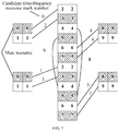
- FIG. 7 is a schematic diagram of a reference signal pattern according to another embodiment of the present invention.
- FIG. 7 assuming that there are 10 small cells in a surrounding small cell cluster, which respectively use reference signal resource patterns of candidate time-frequency resource mark numbers 0 to 9 in FIG. 7 . Shaded parts are currently configured mute resource patterns.
- a particular muting pattern may be easily selected among multiple cells, so that only a half of resources (for example, the first partial time-frequency resource) of a reference signal in each surrounding cell are muted, to improve signal detection performance.
- the other half of resources for example, the second partial time-frequency resource
- the UE may perform RRM measurement on a surrounding small cell based on configurations of the foregoing time-frequency resource and mute time-frequency resource. Specifically, as shown in FIG. 7 , the UE may determine, according to receive power of the reference signal detected on a first partial time-frequency resource (a mute time-frequency resource of another cell) in a candidate time-frequency resource 0, or detected on a first partial time-frequency resource and a second partial time-frequency resource (where another cell is not muted) in a candidate time-frequency resource 0, RSRP of the measured cell corresponding to the candidate time-frequency resource 0.
- a base station may notify in advance the UE of a mute time-frequency resource of another cell.
- the base station notifies the UE that a first partial resource in a time-frequency resource 0 of the measured cell is a mute resource, and a second partial resource is not a mute resource. Then, the UE may perform RSRP measurement according to only the first partial resource, or the UE may measure RSRP according to all time-frequency resources 0 (where in this case, data interference from a neighboring cell may occur in the second partial resource).
- the UE may determine an RSSI of the current cell according to total receive power on the second partial time-frequency resource of the candidate time-frequency resource 0, or according to total receive power on a first resource to which the second partial time-frequency resource of the candidate time-frequency resource 0 belongs, where the first resource is any one of an OFDM symbol, a timeslot, a subframe, or a subframe set.
- the base station may notify in advance the UE of a mute time-frequency resource of another cell. For example, the base station notifies the UE that a first partial resource in the time-frequency resource 0 of the measured cell is a mute resource, and a second partial resource is not a mute resource.
- RSRQ may be determined by using the foregoing obtained RSRP and RSSI.
- RSRQ may be determined by using a ratio of the RSRP to the RSSI.
- UE can detect a cell according to a reference signal in a mute resource and measure RSRP of the cell, and can determine an RSSI according to a signal in a non-mute resource, so that the UE reaches a compromise between two aspects: cell discovery/detection performance and interference measurement, and RSRP and RSSI measurement can be performed by using only one type of reference signal, thereby simplifying a design, and making overheads for muting relatively low.
- FIG. 8 is a schematic diagram of a reference signal pattern according to another embodiment of the present invention. Compared with the embodiment of FIG. 6 , in the embodiment of FIG. 8 , configuration information allows candidate time-frequency resources to partially overlap each other, and in this way, information about more types of candidate time-frequency resources may be included.
- the configuration information may further include at least one third candidate time-frequency resource, where the third candidate time-frequency resource includes a fifth partial time-frequency resource and a sixth partial time-frequency resource, the fifth partial time-frequency resource and the first partial resource overlap completely, the sixth partial time-frequency resource and the second partial resource do not overlap, the sixth partial time-frequency resource and the third partial resource do not overlap, the sixth partial time-frequency resource and the fourth partial resource do not overlap, and the sixth partial time-frequency resource is a partial resource in a third mute time-frequency resource.
- FIG. 8 it can be seen that, four REs whose mark numbers are 8 in FIG. 8 are third mute time-frequency resources, where a part (two REs on top) of the third mute time-frequency resources are sixth partial time-frequency resources.
- the sixth partial time-frequency resource and a fifth partial time-frequency resource in a first mute time-frequency resource form a third candidate time-frequency resource, where the fifth partial time-frequency resource and the first partial resource (that is, two REs on the top of the first mute time-frequency resource) overlap completely.
- the sixth partial time-frequency resource and the second partial resource do not overlap completely, and the third partial resource and the fourth partial resource do not overlap completely, that is, the first candidate time-frequency resource and the third candidate time-frequency resource overlap partially. This can improve reuse efficiency of a time-frequency resource, that is, reference signals of more cells can be provided in a same resource pool.
- the first partial time-frequency resource and the second partial time-frequency resource may be at different moments, and the third partial time-frequency resource and the fourth partial time-frequency resource may be at different moments.
- the first partial time-frequency resource and the second partial time-frequency resource are at a same moment, and the third partial time-frequency resource and the fourth partial time-frequency resource are at a same moment and a frequency domain subcarrier of the third partial time-frequency resource and a frequency domain subcarrier of the fourth partial time-frequency resource are adjacent.
- the different moments may be different symbols in a same subframe, different subframes in a same radio frame, different radio frames, or the like.
- the first partial time-frequency resource and the second partial time-frequency resource are at different moments
- the third partial time-frequency resource and the fourth partial time-frequency resource are at different moments, where the different moments are different symbols in a same subframe.
- separation in some symbols may ensure greater estimation accuracy of frequency domain synchronization.
- two partial time-frequency resources in a candidate time-frequency resource 8 or 9 are at a same moment, and in this example, the same moment is a same symbol in a same subframe. This can ensure greater accuracy of timing estimation.
- the configuration information may further include at least one candidate sequence, where the candidate sequence includes a frequency domain scrambling code and/or a time domain orthogonal code.
- a frequency domain scrambling code corresponding to the first partial time-frequency resource may be the same as a frequency domain scrambling code corresponding to the second partial time-frequency resource, but a time domain orthogonal code corresponding to the first partial time-frequency resource is different from a time domain orthogonal code corresponding to the second partial time-frequency resource.
- a frequency domain scrambling code corresponding to the first partial time-frequency resource may be different from a frequency domain scrambling code corresponding to the second partial time-frequency resource, but a time domain orthogonal code corresponding to the first partial time-frequency resource is the same as a time domain orthogonal code corresponding to the second partial time-frequency resource.
- the foregoing configuration information may further include at least one candidate sequence, where the candidate sequence includes a frequency domain scrambling code and a time domain orthogonal code.
- the candidate sequence includes a frequency domain scrambling code and a time domain orthogonal code.
- a pseudo frequency domain random sequence is first generated in a frequency domain direction, which may be specifically an m sequence or a Gold sequence.
- a spread spectrum operation may further be performed in a time domain by using a Walsh (Walsh) sequence.
- Walsh Walsh
- ⁇ 1, 1 ⁇ or ⁇ 1, -1 ⁇ is used in two consecutive OFDM symbols to perform an orthogonal code spread spectrum operation.
- FIG. 9 it can be seen that, in two candidate time-frequency resources whose candidate time-frequency resource mark numbers are 0 and 8, first partial time-frequency resources (whose mark number is 0) overlap completely, and second partial time-frequency resources do not overlap completely, and mark numbers of the second partial time-frequency resources are separately 2 and 4.
- the two candidate time-frequency resources whose mark numbers are separately 0 and 8 may be respectively allocated to two cells, to be used as the foregoing reference signals. In this case, there are two methods for distinguishing the two cells.
- the two cells use different scrambling code sequences, that is, initial parameters of the foregoing formula are different.
- time domain orthogonal codes may be the same. For example, ⁇ 1, 1 ⁇ is used for spread spectrum.
- the two cells use a same scrambling code sequence, that is, initial parameters of the foregoing formula are the same.
- time domain orthogonal codes are different. For example, for a cell 1, ⁇ 1, 1 ⁇ is used for spread spectrum, and for a cell 2, ⁇ 1, -1 ⁇ is used for spread spectrum.
- the second method may provide an orthogonal inter-cell reference signal sequence design, that is, reference signal sequences sent by the two cells are completely orthogonal, that is, there is no interference, and detection performance is relatively desirable.
- FIG. 10 is a schematic diagram of a reference signal pattern according to another embodiment of the present invention.
- a set of candidate time-frequency resources may be preconfigured, for example, as shown by mark numbers 0 to 9 in FIG. 10 . If the preconfigured candidate time-frequency resource is not rewritten according to signaling of a base station, both UE and the base station use, by default, the preconfigured set of candidate time-frequency resources to receive and send the foregoing reference signal.
- to send a reference signal based on a preconfigured candidate time-frequency resource may cause a problem.
- a surrounding cell is dynamically or semi-statically turned on and off, in a particular period of time, there is a great difference between interference in some reference signal resources and interference in some other reference signal resources, causing a decrease in cell discovery and RRM measurement performance.
- a network side device may notify, by using auxiliary signaling, the UE of current auxiliary configuration information.
- the auxiliary configuration information indicates information about another candidate time-frequency resource except preconfigured configuration information.
- the auxiliary configuration information includes at least one fourth candidate time-frequency resource, and the fourth candidate time-frequency resource includes a first partial time-frequency resource and a fourth partial time-frequency resource. Specifically, as shown by REs circled by ellipses in FIG.
- the first partial time-frequency resource included in the fourth candidate time-frequency resource is a part (the top two REs whose mark numbers are 0) of a time-frequency resource whose mark number is 0, and the fourth partial time-frequency resource included in the fourth candidate time-frequency resource is a part (the top two REs whose mark numbers are 4) of a time-frequency resource whose mark number is 4. It can be seen that, the configuration of the fourth candidate time-frequency resource does not fall within the foregoing preconfigured 10 candidate time-frequency resources 0 to 9. In this way, a problem in the foregoing scenario may be resolved.
- FIG. 11 is a flowchart of a reference signal detection method according to an embodiment of the present invention. The method of FIG. 11 is performed by UE.
- the first candidate time-frequency resource includes a first partial time-frequency resource and a second partial time-frequency resource, the first partial time-frequency resource is a first partial resource in a first mute time-frequency resource, and the second partial time-frequency resource is a second partial resource in a second mute time-frequency resource.
- the second candidate time-frequency resource includes a third partial time-frequency resource and a fourth partial time-frequency resource, the third partial time-frequency resource is a third partial resource in the first mute time-frequency resource, and the fourth partial time-frequency resource is a fourth partial resource in the second mute time-frequency resource.
- the first partial resource, the second partial resource, the third partial resource, and the fourth partial resource do not overlap one another.
- partial resources are separately selected from different mute time-frequency resources and combined to be used as candidate time-frequency resources, and partial resources occupied by different candidate time-frequency resources do not overlap one another.
- Such a reference signal design manner can meet a requirement of discovering a reference signal, and improve cell discovery and measurement performance.
- one neighboring cell may send a reference signal by using the foregoing first candidate time-frequency resource, and the other neighboring cell may send a reference signal by using the second candidate time-frequency resource.
- the time-frequency resources occupied by the two neighboring cells to send the reference signals are at different time or are on different frequencies or are at different time and on different frequencies, to avoid interference between the reference signals sent by the two neighboring cells.
- candidate time-frequency resources are designed without considering mute time-frequency resources, if a reference signal needs to be completely prevented from interference, there may be a great many of times and frequencies that need to be muted by surrounding cells, causing an increase in overheads for muting.
- other surrounding cells only need to mute the foregoing first mute time-frequency resource and second mute time-frequency resource, to prevent the reference signals of the foregoing two neighboring cells from interference, and therefore, overheads for muting are relatively low.
- RSRP of a current cell may be determined according to receive power of the reference signal detected on the first partial time-frequency resource, or RSRP of a current cell is determined according to receive power of the reference signal detected on the first partial time-frequency resource and the second partial time-frequency resource.
- a received signal strength indicator RSSI of the current cell may be determined according to total receive power on the second partial time-frequency resource or a first resource to which the second partial time-frequency resource belongs, where the first resource is any one of an OFDM symbol, a timeslot, a subframe, or a subframe set.
- RSRQ of the current cell may be determined according to the RSRP and the RSSI.
- this embodiment of the present invention may be extended to more manners of configuring candidate time-frequency resources.
- the configuration information may further include information about a third candidate time-frequency resource.
- the third candidate time-frequency resource includes a fifth partial time-frequency resource and a sixth partial time-frequency resource, the fifth partial time-frequency resource and the first partial resource overlap completely, the sixth partial time-frequency resource and the second partial resource do not overlap, the sixth partial time-frequency resource and the third partial resource do not overlap, the sixth partial time-frequency resource and the fourth partial resource do not overlap, and the sixth partial time-frequency resource is a partial resource in a third mute time-frequency resource.
- More types of candidate time-frequency resources may be similarly configured in such a manner.
- a first candidate time-frequency resource, a second candidate time-frequency resource, a first mute time-frequency resource, and a second mute time-frequency resource may all belong to a time-frequency resource pool of a CSI-RS, or a time-frequency resource pool of a CRS, or a time-frequency resource pool of a PSS, or a time-frequency resource pool of an SSS.
- the reference signal in this embodiment of the present invention may be designed based on a resource pattern of an existing reference signal.
- a resource of the existing reference signal may be reused.
- this embodiment of the present invention is not limited thereto.
- a newly designed reference signal may also be used.
- the first partial time-frequency resource and the second partial time-frequency resource are at different moments, and the third partial time-frequency resource and the fourth partial time-frequency resource are at different moments. In this way, separation in some symbols may ensure greater estimation accuracy of frequency domain synchronization.
- the first partial time-frequency resource and the second partial time-frequency resource are at a same moment
- the third partial time-frequency resource and the fourth partial time-frequency resource are at a same moment and a frequency domain subcarrier of the third partial time-frequency resource and a frequency domain subcarrier of the fourth partial time-frequency resource are adjacent. This can ensure greater accuracy of timing estimation.
- the configuration information may further include information about at least one candidate sequence, where the candidate sequence includes a frequency domain scrambling code and/or a time domain orthogonal code.
- a frequency domain scrambling code corresponding to the first partial time-frequency resource is the same as a frequency domain scrambling code corresponding to the second partial time-frequency resource, and a time domain orthogonal code corresponding to the first partial time-frequency resource is different from a time domain orthogonal code corresponding to the second partial time-frequency resource.
- a frequency domain scrambling code corresponding to the first partial time-frequency resource is different from a frequency domain scrambling code corresponding to the second partial time-frequency resource, and a time domain orthogonal code corresponding to the first partial time-frequency resource is the same as a time domain orthogonal code corresponding to the second partial time-frequency resource.
- reference signal sequences sent by two cells are orthogonal with each other without interference, which can improve detection performance.
- the configuration information that is preconfigured may be obtained.
- the configuration information may be specified in a standard, or may be set by means of negotiation performed in advance by receiving and sending ends. This facilitates generation and detection of a reference signal.
- auxiliary signaling sent by a network side device may further be obtained, where the auxiliary signaling is used to indicate information about a fourth candidate time-frequency resource, and the fourth candidate time-frequency resource includes the first partial time-frequency resource and the fourth partial time-frequency resource.
- a network side may rewrite a preconfigured candidate time-frequency resource by using the auxiliary signaling, and therefore, a reference signal can be more flexibly generated and detected.
- FIG. 12 is a flowchart of a reference signal sending method according to an embodiment of the present invention. The method of FIG. 12 is performed by a base station.
- the first candidate time-frequency resource includes a first partial time-frequency resource and a second partial time-frequency resource, the first partial time-frequency resource is a first partial resource in a first mute time-frequency resource, and the second partial time-frequency resource is a second partial resource in a second mute time-frequency resource.
- the second candidate time-frequency resource includes a third partial time-frequency resource and a fourth partial time-frequency resource, the third partial time-frequency resource is a third partial resource in the first mute time-frequency resource, and the fourth partial time-frequency resource is a fourth partial resource in the second mute time-frequency resource.
- the first partial resource, the second partial resource, the third partial resource, and the fourth partial resource do not overlap one another.
- partial resources are separately selected from different mute time-frequency resources and combined to be used as candidate time-frequency resources, and partial resources occupied by different candidate time-frequency resources do not overlap one another.
- Such a reference signal design manner can meet a requirement of discovering a reference signal, and improve cell discovery and measurement performance.
- one neighboring cell may send a reference signal by using the foregoing first candidate time-frequency resource, and the other neighboring cell may send a reference signal by using the second candidate time-frequency resource.
- the time-frequency resources occupied by the two neighboring cells to send the reference signals are at different time or are on different frequencies or are at different time and on different frequencies, to avoid interference between the reference signals sent by the two neighboring cells.
- candidate time-frequency resources are designed without considering mute time-frequency resources, if a reference signal needs to be completely prevented from interference, there may be a great many of times and frequencies that need to be muted by surrounding cells, causing an increase in overheads for muting.
- other surrounding cells only need to mute the foregoing first mute time-frequency resource and second mute time-frequency resource, to prevent the reference signals of the foregoing two neighboring cells from interference, and therefore, overheads for muting are relatively low.
- the configuration information may further include information about a third candidate time-frequency resource, where the third candidate time-frequency resource includes a fifth partial time-frequency resource and a sixth partial time-frequency resource, the fifth partial time-frequency resource and the first partial resource overlap completely, the sixth partial time-frequency resource and the second partial resource do not overlap, the sixth partial time-frequency resource and the third partial resource do not overlap, the sixth partial time-frequency resource and the fourth partial resource do not overlap, and the sixth partial time-frequency resource is a partial resource in a third mute time-frequency resource.
- More types of candidate time-frequency resources may be similarly configured in such a manner.
- a first candidate time-frequency resource, a second candidate time-frequency resource, a first mute time-frequency resource, and a second mute time-frequency resource may all belong to a time-frequency resource pool of a CSI-RS, or a time-frequency resource pool of a CRS, or a time-frequency resource pool of a PSS, or a time-frequency resource pool of an SSS.
- the reference signal in this embodiment of the present invention may be designed based on a resource pattern of an existing reference signal.
- a resource of the existing reference signal may be reused.
- this embodiment of the present invention is not limited thereto.
- a newly designed reference signal may also be used.
- the first partial time-frequency resource and the second partial time-frequency resource are at different moments, and the third partial time-frequency resource and the fourth partial time-frequency resource are at different moments. In this way, separation in some symbols may ensure greater estimation accuracy of frequency domain synchronization.
- the first partial time-frequency resource and the second partial time-frequency resource are at a same moment
- the third partial time-frequency resource and the fourth partial time-frequency resource are at a same moment and a frequency domain subcarrier of the third partial time-frequency resource and a frequency domain subcarrier of the fourth partial time-frequency resource are adjacent. This can ensure greater accuracy of timing estimation.
- the configuration information may further include information about at least one candidate sequence, where the candidate sequence includes a frequency domain scrambling code and/or a time domain orthogonal code.
- a frequency domain scrambling code corresponding to the first partial time-frequency resource is the same as a frequency domain scrambling code corresponding to the second partial time-frequency resource, and a time domain orthogonal code corresponding to the first partial time-frequency resource is different from a time domain orthogonal code corresponding to the second partial time-frequency resource.
- a frequency domain scrambling code corresponding to the first partial time-frequency resource is different from a frequency domain scrambling code corresponding to the second partial time-frequency resource, and a time domain orthogonal code corresponding to the first partial time-frequency resource is the same as a time domain orthogonal code corresponding to the second partial time-frequency resource.
- reference signal sequences sent by two cells are orthogonal with each other without interference, which can improve detection performance.
- the configuration information may be preconfigured.
- the configuration information may be specified in a standard, or may be set by means of negotiation performed in advance by receiving and sending ends. This facilitates generation and detection of a reference signal.
- the base station may further send auxiliary signaling, where the auxiliary signaling is used to indicate information about a fourth candidate time-frequency resource, and the fourth candidate time-frequency resource includes the first partial time-frequency resource and the fourth partial time-frequency resource.
- auxiliary signaling is used to indicate information about a fourth candidate time-frequency resource
- the fourth candidate time-frequency resource includes the first partial time-frequency resource and the fourth partial time-frequency resource.
- FIG. 13 is a block diagram of user equipment according to another embodiment of the present invention.
- the user equipment 130 in FIG. 13 includes a processor 131, a memory 132, a receiver circuit 133, and a transmitter circuit 134.
- the processor 131, the memory 132, the receiver circuit 133, and the transmitter circuit 134 are connected to one another by using a bus system 139.
- the user equipment 130 may further include an antenna 135, or the like.
- the processor 131 controls an operation of the user equipment 130.
- the memory 132 may include a read-only memory and a random access memory, and provides an instruction and data to the processor 131. A part of the memory 132 may further include a non-volatile random access memory (NVRAM).
- NVRAM non-volatile random access memory
- the transmitter circuit 134 and the receiver circuit 133 may be coupled to the antenna 135.
- Components of the user equipment 130 are coupled together by using the bus system 139, where in addition to a data bus, the bus system 139 may further include a power bus, a control bus, a status signal bus, and the like. However, for clear description, various types of buses in the figure are marked as the bus system 139.
- the processor 131 may be an integrated circuit chip and has a signal processing capability.
- the foregoing processor 131 may be a general purpose processor, a digital signal processor (DSP), an application-specific integrated circuit (ASIC), a field programmable gate array (FPGA), or another programmable logic device, discrete gate or transistor logic device, or discrete hardware component.
- the processor 131 may implement or execute methods, steps and logical block diagrams disclosed in the embodiments of the present invention.
- the general purpose processor may be a microprocessor or the processor may be any conventional processor and the like.
- the processor 131 reads information in the memory 132, and controls components of the user equipment 130 in combination with hardware of the user equipment 130.
- the method of FIG. 11 may be implemented in the user equipment 130 in FIG. 13 . To avoid repetition, details are not described again.
- the processor 131 may determine configuration information of a reference signal, where the configuration information includes information about a first candidate time-frequency resource and information about a second candidate time-frequency resource.
- the first candidate time-frequency resource may include a first partial time-frequency resource and a second partial time-frequency resource, the first partial time-frequency resource is a first partial resource in a first mute (Mute) time-frequency resource, and the second partial time-frequency resource is a second partial resource in a second mute time-frequency resource.
- first partial time-frequency resource is a first partial resource in a first mute (Mute) time-frequency resource
- the second partial time-frequency resource is a second partial resource in a second mute time-frequency resource.
- the second candidate time-frequency resource may include a third partial time-frequency resource and a fourth partial time-frequency resource, where the third partial time-frequency resource is a third partial resource in the first mute time-frequency resource, and the fourth partial time-frequency resource is a fourth partial resource in the second mute time-frequency resource.
- the foregoing first partial resource, second partial resource, third partial resource, and fourth partial resource do not overlap one another.
- the receiver circuit 133 may detect the reference signal according to the configuration information.
- partial resources are separately selected from different mute time-frequency resources and combined to be used as candidate time-frequency resources, and partial resources occupied by different candidate time-frequency resources do not overlap one another.
- Such a reference signal design manner can meet a requirement of discovering a reference signal, and improve cell discovery and measurement performance.
- one neighboring cell may send a reference signal by using the foregoing first candidate time-frequency resource, and the other neighboring cell may send a reference signal by using the second candidate time-frequency resource.
- the time-frequency resources occupied by the two neighboring cells to send the reference signals are at different time or are on different frequencies or are at different time and on different frequencies, to avoid interference between the reference signals sent by the two neighboring cells.
- candidate time-frequency resources are designed without considering mute time-frequency resources, if a reference signal needs to be completely prevented from interference, there may be a great many of times and frequencies that need to be muted by surrounding cells, causing an increase in overheads for muting.
- other surrounding cells only need to mute the foregoing first mute time-frequency resource and second mute time-frequency resource, to prevent the reference signals of the foregoing two neighboring cells from interference, and therefore, overheads for muting are relatively low.
- the processor 131 may determine RSRP of a current cell according to receive power of the reference signal detected on the first partial time-frequency resource, or determine RSRP of a current cell according to receive power of the reference signal detected on the first partial time-frequency resource and the second partial time-frequency resource.
- the processor 131 may determine an RSSI of the current cell according to total receive power on the second partial time-frequency resource or a first resource to which the second partial time-frequency resource belongs, where the first resource is any one of an OFDM symbol, a timeslot, a subframe, or a subframe set.
- the processor 131 may determine RSRQ of the current cell according to the RSRP and the RSSI.
- this embodiment of the present invention may be extended to more manners of configuring candidate time-frequency resources.
- the configuration information determined by the processor 131 may further include information about a third candidate time-frequency resource.
- the third candidate time-frequency resource includes a fifth partial time-frequency resource and a sixth partial time-frequency resource, the fifth partial time-frequency resource and the first partial resource overlap completely, the sixth partial time-frequency resource and the second partial resource do not overlap, the sixth partial time-frequency resource and the third partial resource do not overlap, the sixth partial time-frequency resource and the fourth partial resource do not overlap, and the sixth partial time-frequency resource is a partial resource in a third mute time-frequency resource.
- More types of candidate time-frequency resources may be similarly configured in such a manner.
- a first candidate time-frequency resource, a second candidate time-frequency resource, a first mute time-frequency resource, and a second mute time-frequency resource may all belong to a time-frequency resource pool of a CSI-RS, or a time-frequency resource pool of a CRS, or a time-frequency resource pool of a PSS, or a time-frequency resource pool of an SSS.
- the reference signal in this embodiment of the present invention may be designed based on a resource pattern of an existing reference signal.
- a resource of the existing reference signal may be reused.
- this embodiment of the present invention is not limited thereto.
- a newly designed reference signal may also be used.
- the first partial time-frequency resource and the second partial time-frequency resource are at different moments, and the third partial time-frequency resource and the fourth partial time-frequency resource are at different moments. In this way, separation in some symbols may ensure greater estimation accuracy of frequency domain synchronization.
- the first partial time-frequency resource and the second partial time-frequency resource are at a same moment
- the third partial time-frequency resource and the fourth partial time-frequency resource are at a same moment and a frequency domain subcarrier of the third partial time-frequency resource and a frequency domain subcarrier of the fourth partial time-frequency resource are adjacent. This can ensure greater accuracy of timing estimation.
- the configuration information determined by the processor 131 may further include information about at least one candidate sequence, where the candidate sequence includes a frequency domain scrambling code and/or a time domain orthogonal code.
- a frequency domain scrambling code corresponding to the first partial time-frequency resource is the same as a frequency domain scrambling code corresponding to the second partial time-frequency resource, and a time domain orthogonal code corresponding to the first partial time-frequency resource is different from a time domain orthogonal code corresponding to the second partial time-frequency resource.
- a frequency domain scrambling code corresponding to the first partial time-frequency resource is different from a frequency domain scrambling code corresponding to the second partial time-frequency resource, and a time domain orthogonal code corresponding to the first partial time-frequency resource is the same as a time domain orthogonal code corresponding to the second partial time-frequency resource.
- reference signal sequences sent by two cells are orthogonal with each other without interference, which can improve detection performance.
- the processor 131 may obtain the configuration information that is preconfigured.
- the configuration information may be specified in a standard, or may be set by means of negotiation performed in advance by receiving and sending ends. This facilitates generation and detection of a reference signal.
- the processor 131 may further obtain auxiliary signaling sent by a network side device, where the auxiliary signaling is used to indicate information about a fourth candidate time-frequency resource, and the fourth candidate time-frequency resource includes the first partial time-frequency resource and the fourth partial time-frequency resource.
- a network side may rewrite a preconfigured candidate time-frequency resource by using the auxiliary signaling, and therefore, a reference signal can be more flexibly generated and detected.
- FIG. 14 is a block diagram of a base station according to another embodiment of the present invention.
- the base station 140 in FIG. 14 includes a processor 141, a memory 142, a receiver circuit 143, and a transmitter circuit 144.
- the processor 141, the memory 142, the receiver circuit 143, and the transmitter circuit 144 are connected to one another by using a bus system 149.
- the base station 140 may further include an antenna 145, or the like.
- the processor 141 controls an operation of the base station 140.
- the memory 142 may include a read-only memory and a random access memory, and provides an instruction and data to the processor 141. A part of the memory 142 may further include a non-volatile random access memory (NVRAM).
- NVRAM non-volatile random access memory
- the transmitter circuit 144 and the receiver circuit 143 may be coupled to the antenna 145.
- Components of the base station 140 are coupled together by using the bus system 149, where in addition to a data bus, the bus system 149 may further include a power bus, a control bus, a status signal bus, and the like. However, for clear description, various types of buses in the figure are marked as the bus system 149.
- the processor 141 may be an integrated circuit chip and has a signal processing capability.
- the foregoing processor 141 may be a general purpose processor, a digital signal processor (DSP), an application-specific integrated circuit (ASIC), a field programmable gate array (FPGA), or another programmable logic device, discrete gate or transistor logic device, or discrete hardware component.
- the processor 141 may implement or execute methods, steps and logical block diagrams disclosed in the embodiments of the present invention.
- the general purpose processor may be a microprocessor or the processor may be any conventional processor and the like.
- the processor 141 reads information in the memory 142, and controls components of the base station 140 in combination with hardware of the base station 140.
- the method of FIG. 12 may be implemented in the base station 140 in FIG. 14 . To avoid repetition, details are not described again.
- the processor 141 may determine a sending resource of a reference signal, where the sending resource of the reference signal is selected from configuration information of the reference signal, and the configuration information includes information about a first candidate time-frequency resource and information about a second candidate time-frequency resource.
- the first candidate time-frequency resource includes a first partial time-frequency resource and a second partial time-frequency resource, the first partial time-frequency resource is a first partial resource in a first mute time-frequency resource, and the second partial time-frequency resource is a second partial resource in a second mute time-frequency resource.
- the second candidate time-frequency resource includes a third partial time-frequency resource and a fourth partial time-frequency resource, the third partial time-frequency resource is a third partial resource in the first mute time-frequency resource, and the fourth partial time-frequency resource is a fourth partial resource in the second mute time-frequency resource.
- the first partial resource, the second partial resource, the third partial resource, and the fourth partial resource do not overlap one another.
- the transmitter circuit 144 may be configured to send the reference signal according to the sending resource of the reference signal.
- partial resources are separately selected from different mute time-frequency resources and combined to be used as candidate time-frequency resources, and partial resources occupied by different candidate time-frequency resources do not overlap one another.
- Such a reference signal design manner can meet a requirement of discovering a reference signal, and improve cell discovery and measurement performance.
- one neighboring cell may send a reference signal by using the foregoing first candidate time-frequency resource, and the other neighboring cell may send a reference signal by using the second candidate time-frequency resource.
- the time-frequency resources occupied by the two neighboring cells to send the reference signals are at different time or are on different frequencies or are at different time and on different frequencies, to avoid interference between the reference signals sent by the two neighboring cells.
- candidate time-frequency resources are designed without considering mute time-frequency resources, if a reference signal needs to be completely prevented from interference, there may be a great many of times and frequencies that need to be muted by surrounding cells, causing an increase in overheads for muting.
- other surrounding cells only need to mute the foregoing first mute time-frequency resource and second mute time-frequency resource, to prevent the reference signals of the foregoing two neighboring cells from interference, and therefore, overheads for muting are relatively low.
- the configuration information may further include information about a third candidate time-frequency resource, where the third candidate time-frequency resource includes a fifth partial time-frequency resource and a sixth partial time-frequency resource, the fifth partial time-frequency resource and the first partial resource overlap completely, the sixth partial time-frequency resource and the second partial resource do not overlap, the sixth partial time-frequency resource and the third partial resource do not overlap, the sixth partial time-frequency resource and the fourth partial resource do not overlap, and the sixth partial time-frequency resource is a partial resource in a third mute time-frequency resource.
- More types of candidate time-frequency resources may be similarly configured in such a manner.
- a first candidate time-frequency resource, a second candidate time-frequency resource, a first mute time-frequency resource, and a second mute time-frequency resource may all belong to a time-frequency resource pool of a CSI-RS, or a time-frequency resource pool of a CRS, or a time-frequency resource pool of a PSS, or a time-frequency resource pool of an SSS.
- the reference signal in this embodiment of the present invention may be designed based on a resource pattern of an existing reference signal.
- a resource of the existing reference signal may be reused.
- this embodiment of the present invention is not limited thereto.
- a newly designed reference signal may also be used.
- the first partial time-frequency resource and the second partial time-frequency resource are at different moments, and the third partial time-frequency resource and the fourth partial time-frequency resource are at different moments. In this way, separation in some symbols may ensure greater estimation accuracy of frequency domain synchronization.
- the first partial time-frequency resource and the second partial time-frequency resource are at a same moment
- the third partial time-frequency resource and the fourth partial time-frequency resource are at a same moment and a frequency domain subcarrier of the third partial time-frequency resource and a frequency domain subcarrier of the fourth partial time-frequency resource are adjacent. This can ensure greater accuracy of timing estimation.
- the configuration information may further include information about at least one candidate sequence, where the candidate sequence includes a frequency domain scrambling code and/or a time domain orthogonal code.
- a frequency domain scrambling code corresponding to the first partial time-frequency resource is the same as a frequency domain scrambling code corresponding to the second partial time-frequency resource, and a time domain orthogonal code corresponding to the first partial time-frequency resource is different from a time domain orthogonal code corresponding to the second partial time-frequency resource.
- a frequency domain scrambling code corresponding to the first partial time-frequency resource is different from a frequency domain scrambling code corresponding to the second partial time-frequency resource, and a time domain orthogonal code corresponding to the first partial time-frequency resource is the same as a time domain orthogonal code corresponding to the second partial time-frequency resource.
- reference signal sequences sent by two cells are orthogonal with each other without interference, which can improve detection performance.
- the configuration information may be preconfigured.
- the configuration information may be specified in a standard, or may be set by means of negotiation performed in advance by receiving and sending ends. This facilitates generation and detection of a reference signal.
- the transmitter circuit 144 may further send auxiliary signaling, where the auxiliary signaling is used to indicate information about a fourth candidate time-frequency resource, and the fourth candidate time-frequency resource includes the first partial time-frequency resource and the fourth partial time-frequency resource.
- a network side may rewrite a preconfigured candidate time-frequency resource by using the auxiliary signaling, and therefore, a reference signal can be more flexibly generated and detected.
- the disclosed system, apparatus, and method may be implemented in other manners.
- the described apparatus embodiment is merely exemplary.
- the unit division is merely logical function division and may be other division in actual implementation.
- a plurality of units or components may be combined or integrated into another system, or some features may be ignored or not performed.
- the displayed or discussed mutual couplings or direct couplings or communication connections may be implemented by using some interfaces.
- the indirect couplings or communication connections between the apparatuses or units may be implemented in electronic, mechanical, or other forms.
- the units described as separate parts may or may not be physically separate, and parts displayed as units may or may not be physical units, may be located in one position, or may be distributed on a plurality of network units. Some or all of the units may be selected according to actual needs to achieve the objectives of the solutions of the embodiments.
- functional units in the embodiments of the present invention may be integrated into one processing unit, or each of the units may exist alone physically, or two or more units are integrated into one unit.
- the functions When the functions are implemented in the form of a software functional unit and sold or used as an independent product, the functions may be stored in a computer-readable storage medium. Based on such an understanding, the technical solutions of the present invention essentially, or the part contributing to the prior art, or some of the technical solutions may be implemented in a form of a software product.
- the computer software product is stored in a storage medium, and includes several instructions for instructing a computer device (which may be a personal computer, a server, a network device, or the like) to perform all or some of the steps of the methods described in the embodiments of the present invention.
- the foregoing storage medium includes: any medium that can store program code, for example, a USB flash drive, a removable hard disk, a read-only memory (ROM, Read-Only Memory), a random access memory (RAM, Random Access Memory), a magnetic disk, or an optical disc.
- a USB flash drive for example, a USB flash drive, a removable hard disk, a read-only memory (ROM, Read-Only Memory), a random access memory (RAM, Random Access Memory), a magnetic disk, or an optical disc.
Landscapes
- Engineering & Computer Science (AREA)
- Signal Processing (AREA)
- Computer Networks & Wireless Communication (AREA)
- Quality & Reliability (AREA)
- Computer Security & Cryptography (AREA)
- Physics & Mathematics (AREA)
- Electromagnetism (AREA)
- Mobile Radio Communication Systems (AREA)
Applications Claiming Priority (1)
| Application Number | Priority Date | Filing Date | Title |
|---|---|---|---|
| PCT/CN2014/074796 WO2015149349A1 (zh) | 2014-04-04 | 2014-04-04 | 参考信号的检测方法、接收方法、用户设备和基站 |
Publications (3)
| Publication Number | Publication Date |
|---|---|
| EP3119121A1 EP3119121A1 (en) | 2017-01-18 |
| EP3119121A4 EP3119121A4 (en) | 2017-04-12 |
| EP3119121B1 true EP3119121B1 (en) | 2020-06-03 |
Family
ID=54239320
Family Applications (1)
| Application Number | Title | Priority Date | Filing Date |
|---|---|---|---|
| EP14887781.4A Active EP3119121B1 (en) | 2014-04-04 | 2014-04-04 | Reference signal detection method, receiving method, user equipment and base station |
Country Status (6)
| Country | Link |
|---|---|
| US (1) | US10291374B2 (zh) |
| EP (1) | EP3119121B1 (zh) |
| KR (1) | KR20160138553A (zh) |
| CN (1) | CN105284143B (zh) |
| BR (1) | BR112016022740A2 (zh) |
| WO (1) | WO2015149349A1 (zh) |
Families Citing this family (16)
| Publication number | Priority date | Publication date | Assignee | Title |
|---|---|---|---|---|
| CN111490814B (zh) * | 2016-07-11 | 2021-06-25 | 上海朗帛通信技术有限公司 | 一种无线传输中的方法和装置 |
| CN110430612B (zh) * | 2016-09-19 | 2021-10-29 | 上海朗帛通信技术有限公司 | 一种ue、基站中的支持发射功率调整的方法和装置 |
| EP3506707B1 (en) * | 2016-09-21 | 2022-04-27 | Guangdong Oppo Mobile Telecommunications Corp., Ltd. | Signal transmission method and apparatus |
| CN107888352B (zh) * | 2016-09-29 | 2020-06-02 | 华为技术有限公司 | 参考信号的处理方法、用户设备和基站 |
| CN108173798B (zh) * | 2016-12-07 | 2020-07-31 | 上海朗帛通信技术有限公司 | 一种无线通信中的方法和装置 |
| EP4138334A1 (en) * | 2017-03-24 | 2023-02-22 | Apple Inc. | Design of cell specific reference signal (crs) muting for even further enhanced machine type communication (efemtc) |
| CN108809583B (zh) * | 2017-05-05 | 2024-03-26 | 华为技术有限公司 | 传输信号的方法和装置 |
| WO2019213923A1 (en) * | 2018-05-10 | 2019-11-14 | Nokia Shanghai Bell Co., Ltd. | Method and device for measurement restriction |
| CN111478739B (zh) * | 2019-01-23 | 2022-06-07 | 中国移动通信有限公司研究院 | 获取邻区干扰值的方法、参考信号配置方法及装置 |
| CN112040543B (zh) * | 2019-06-04 | 2024-04-12 | 上海朗帛通信技术有限公司 | 一种被用于无线通信的节点中的方法和装置 |
| CN112188620B (zh) * | 2019-07-01 | 2022-04-05 | 华为技术有限公司 | 一种通信方法及装置 |
| WO2021062821A1 (zh) * | 2019-09-30 | 2021-04-08 | 华为技术有限公司 | 信息处理及信息指示方法和装置 |
| US11800405B2 (en) | 2019-11-06 | 2023-10-24 | Apple Inc. | Systems and methods for cooperative communication using interfering signals |
| CN111901874A (zh) * | 2020-04-13 | 2020-11-06 | 中兴通讯股份有限公司 | 一种参考信号资源的配置方法、装置、设备及储存介质 |
| CN116939645A (zh) * | 2022-03-31 | 2023-10-24 | 北京三星通信技术研究有限公司 | 通信方法、用户设备及基站 |
| CN117793818A (zh) * | 2022-09-21 | 2024-03-29 | 华为技术有限公司 | 测量小区的方法与装置 |
Family Cites Families (8)
| Publication number | Priority date | Publication date | Assignee | Title |
|---|---|---|---|---|
| US20060187887A1 (en) * | 2005-02-18 | 2006-08-24 | Lg Electronics Inc. | Wireless multiple access system for suppressing inter-cell interference |
| KR101619446B1 (ko) * | 2008-12-02 | 2016-05-10 | 엘지전자 주식회사 | 하향링크 mimo시스템에 있어서 rs 전송 방법 |
| CN101772130A (zh) * | 2009-01-07 | 2010-07-07 | 中兴通讯股份有限公司 | 辅助检测信令发送方法 |
| CN102781030A (zh) * | 2011-05-11 | 2012-11-14 | 中兴通讯股份有限公司 | 无线通信系统中的载频信息测量方法及系统 |
| JP2013005288A (ja) * | 2011-06-17 | 2013-01-07 | Sony Corp | 通信端末装置および方法、基地局装置、並びに、通信システム |
| CN102883341B (zh) * | 2011-07-11 | 2015-05-27 | 华为技术有限公司 | 信道信息的测量方法和相关装置 |
| CN102958147B (zh) * | 2011-08-18 | 2016-08-24 | 华为技术有限公司 | 上行功率控制的方法、用户设备和基站 |
| US9008582B2 (en) * | 2011-08-25 | 2015-04-14 | Qualcomm Incorporated | User equipment enhancements for cooperative multi-point communication |
-
2014
- 2014-04-04 CN CN201480000665.0A patent/CN105284143B/zh active Active
- 2014-04-04 BR BR112016022740A patent/BR112016022740A2/pt not_active Application Discontinuation
- 2014-04-04 EP EP14887781.4A patent/EP3119121B1/en active Active
- 2014-04-04 KR KR1020167030288A patent/KR20160138553A/ko active IP Right Grant
- 2014-04-04 WO PCT/CN2014/074796 patent/WO2015149349A1/zh active Application Filing
-
2016
- 2016-10-04 US US15/285,229 patent/US10291374B2/en active Active
Non-Patent Citations (1)
| Title |
|---|
| None * |
Also Published As
| Publication number | Publication date |
|---|---|
| CN105284143B (zh) | 2019-07-12 |
| EP3119121A1 (en) | 2017-01-18 |
| WO2015149349A1 (zh) | 2015-10-08 |
| CN105284143A (zh) | 2016-01-27 |
| BR112016022740A2 (pt) | 2017-08-15 |
| KR20160138553A (ko) | 2016-12-05 |
| US20170033907A1 (en) | 2017-02-02 |
| US10291374B2 (en) | 2019-05-14 |
| EP3119121A4 (en) | 2017-04-12 |
Similar Documents
| Publication | Publication Date | Title |
|---|---|---|
| US10291374B2 (en) | Reference signal detection method and receiving method, user equipment, and base station | |
| US10523392B2 (en) | Downlink reference signals for radio resource management (RRM) measurement | |
| US9603084B2 (en) | Method and apparatus for measuring radio resource management, and method and apparatus for signalling signal to measure radio resource management | |
| US10574279B2 (en) | Method for transmitting reference signal in cell that uses unlicensed frequency band and device | |
| EP2798891B1 (en) | A user equipment and a radio network node, and methods therein | |
| EP2719216B1 (en) | Signal quality measurements of a user equipment on a subset of radio resource elements | |
| US20170150427A1 (en) | Device, Network, and Method of Cell Discovery | |
| TWI470950B (zh) | And a method for eliminating the interference of the cell reference signal | |
| CN111149391B (zh) | 基于用户能力的小区选择 | |
| US11184195B2 (en) | Enhanced SRS frequency hopping scheme for 5G NR | |
| CN111587594B (zh) | 基于独立的辅同步信号的方法及其装置 | |
| EP3319262A1 (en) | Method and device for handling base sequences in a communications network | |
| TWI693840B (zh) | 接收訊號強度指示測量之方法及其使用者設備 | |
| US10091661B2 (en) | Method for receiving a discovery signal from a LAA based cell | |
| US10200939B2 (en) | Method and device for identifying secondary cell on basis of discovery signals | |
| CN108347273B (zh) | 一种数据复用和数据解析方法、装置及系统 | |
| WO2013051285A1 (ja) | 小型基地局及び被干渉端末装置検出方法 | |
| WO2017000263A1 (zh) | 一种参考信号发送方法及装置 | |
| CN109150770B (zh) | 一种参考信号的发送、接收方法及装置 | |
| JP6820554B2 (ja) | 基地局装置 |
Legal Events
| Date | Code | Title | Description |
|---|---|---|---|
| STAA | Information on the status of an ep patent application or granted ep patent |
Free format text: STATUS: THE INTERNATIONAL PUBLICATION HAS BEEN MADE |
|
| PUAI | Public reference made under article 153(3) epc to a published international application that has entered the european phase |
Free format text: ORIGINAL CODE: 0009012 |
|
| STAA | Information on the status of an ep patent application or granted ep patent |
Free format text: STATUS: REQUEST FOR EXAMINATION WAS MADE |
|
| 17P | Request for examination filed |
Effective date: 20161012 |
|
| AK | Designated contracting states |
Kind code of ref document: A1 Designated state(s): AL AT BE BG CH CY CZ DE DK EE ES FI FR GB GR HR HU IE IS IT LI LT LU LV MC MK MT NL NO PL PT RO RS SE SI SK SM TR |
|
| AX | Request for extension of the european patent |
Extension state: BA ME |
|
| A4 | Supplementary search report drawn up and despatched |
Effective date: 20170309 |
|
| RIC1 | Information provided on ipc code assigned before grant |
Ipc: H04W 24/00 20090101AFI20170303BHEP Ipc: H04L 5/00 20060101ALI20170303BHEP |
|
| DAX | Request for extension of the european patent (deleted) | ||
| GRAP | Despatch of communication of intention to grant a patent |
Free format text: ORIGINAL CODE: EPIDOSNIGR1 |
|
| STAA | Information on the status of an ep patent application or granted ep patent |
Free format text: STATUS: GRANT OF PATENT IS INTENDED |
|
| INTG | Intention to grant announced |
Effective date: 20191212 |
|
| GRAS | Grant fee paid |
Free format text: ORIGINAL CODE: EPIDOSNIGR3 |
|
| GRAA | (expected) grant |
Free format text: ORIGINAL CODE: 0009210 |
|
| STAA | Information on the status of an ep patent application or granted ep patent |
Free format text: STATUS: THE PATENT HAS BEEN GRANTED |
|
| AK | Designated contracting states |
Kind code of ref document: B1 Designated state(s): AL AT BE BG CH CY CZ DE DK EE ES FI FR GB GR HR HU IE IS IT LI LT LU LV MC MK MT NL NO PL PT RO RS SE SI SK SM TR |
|
| REG | Reference to a national code |
Ref country code: GB Ref legal event code: FG4D |
|
| REG | Reference to a national code |
Ref country code: CH Ref legal event code: EP Ref country code: AT Ref legal event code: REF Ref document number: 1278373 Country of ref document: AT Kind code of ref document: T Effective date: 20200615 |
|
| REG | Reference to a national code |
Ref country code: DE Ref legal event code: R096 Ref document number: 602014066369 Country of ref document: DE |
|
| REG | Reference to a national code |
Ref country code: LT Ref legal event code: MG4D |
|
| PG25 | Lapsed in a contracting state [announced via postgrant information from national office to epo] |
Ref country code: GR Free format text: LAPSE BECAUSE OF FAILURE TO SUBMIT A TRANSLATION OF THE DESCRIPTION OR TO PAY THE FEE WITHIN THE PRESCRIBED TIME-LIMIT Effective date: 20200904 Ref country code: NO Free format text: LAPSE BECAUSE OF FAILURE TO SUBMIT A TRANSLATION OF THE DESCRIPTION OR TO PAY THE FEE WITHIN THE PRESCRIBED TIME-LIMIT Effective date: 20200903 Ref country code: FI Free format text: LAPSE BECAUSE OF FAILURE TO SUBMIT A TRANSLATION OF THE DESCRIPTION OR TO PAY THE FEE WITHIN THE PRESCRIBED TIME-LIMIT Effective date: 20200603 Ref country code: SE Free format text: LAPSE BECAUSE OF FAILURE TO SUBMIT A TRANSLATION OF THE DESCRIPTION OR TO PAY THE FEE WITHIN THE PRESCRIBED TIME-LIMIT Effective date: 20200603 Ref country code: LT Free format text: LAPSE BECAUSE OF FAILURE TO SUBMIT A TRANSLATION OF THE DESCRIPTION OR TO PAY THE FEE WITHIN THE PRESCRIBED TIME-LIMIT Effective date: 20200603 |
|
| REG | Reference to a national code |
Ref country code: NL Ref legal event code: MP Effective date: 20200603 |
|
| PG25 | Lapsed in a contracting state [announced via postgrant information from national office to epo] |
Ref country code: RS Free format text: LAPSE BECAUSE OF FAILURE TO SUBMIT A TRANSLATION OF THE DESCRIPTION OR TO PAY THE FEE WITHIN THE PRESCRIBED TIME-LIMIT Effective date: 20200603 Ref country code: BG Free format text: LAPSE BECAUSE OF FAILURE TO SUBMIT A TRANSLATION OF THE DESCRIPTION OR TO PAY THE FEE WITHIN THE PRESCRIBED TIME-LIMIT Effective date: 20200903 Ref country code: LV Free format text: LAPSE BECAUSE OF FAILURE TO SUBMIT A TRANSLATION OF THE DESCRIPTION OR TO PAY THE FEE WITHIN THE PRESCRIBED TIME-LIMIT Effective date: 20200603 Ref country code: HR Free format text: LAPSE BECAUSE OF FAILURE TO SUBMIT A TRANSLATION OF THE DESCRIPTION OR TO PAY THE FEE WITHIN THE PRESCRIBED TIME-LIMIT Effective date: 20200603 |
|
| REG | Reference to a national code |
Ref country code: AT Ref legal event code: MK05 Ref document number: 1278373 Country of ref document: AT Kind code of ref document: T Effective date: 20200603 |
|
| PG25 | Lapsed in a contracting state [announced via postgrant information from national office to epo] |
Ref country code: NL Free format text: LAPSE BECAUSE OF FAILURE TO SUBMIT A TRANSLATION OF THE DESCRIPTION OR TO PAY THE FEE WITHIN THE PRESCRIBED TIME-LIMIT Effective date: 20200603 Ref country code: AL Free format text: LAPSE BECAUSE OF FAILURE TO SUBMIT A TRANSLATION OF THE DESCRIPTION OR TO PAY THE FEE WITHIN THE PRESCRIBED TIME-LIMIT Effective date: 20200603 |
|
| PG25 | Lapsed in a contracting state [announced via postgrant information from national office to epo] |
Ref country code: ES Free format text: LAPSE BECAUSE OF FAILURE TO SUBMIT A TRANSLATION OF THE DESCRIPTION OR TO PAY THE FEE WITHIN THE PRESCRIBED TIME-LIMIT Effective date: 20200603 Ref country code: SM Free format text: LAPSE BECAUSE OF FAILURE TO SUBMIT A TRANSLATION OF THE DESCRIPTION OR TO PAY THE FEE WITHIN THE PRESCRIBED TIME-LIMIT Effective date: 20200603 Ref country code: EE Free format text: LAPSE BECAUSE OF FAILURE TO SUBMIT A TRANSLATION OF THE DESCRIPTION OR TO PAY THE FEE WITHIN THE PRESCRIBED TIME-LIMIT Effective date: 20200603 Ref country code: AT Free format text: LAPSE BECAUSE OF FAILURE TO SUBMIT A TRANSLATION OF THE DESCRIPTION OR TO PAY THE FEE WITHIN THE PRESCRIBED TIME-LIMIT Effective date: 20200603 Ref country code: IT Free format text: LAPSE BECAUSE OF FAILURE TO SUBMIT A TRANSLATION OF THE DESCRIPTION OR TO PAY THE FEE WITHIN THE PRESCRIBED TIME-LIMIT Effective date: 20200603 Ref country code: PT Free format text: LAPSE BECAUSE OF FAILURE TO SUBMIT A TRANSLATION OF THE DESCRIPTION OR TO PAY THE FEE WITHIN THE PRESCRIBED TIME-LIMIT Effective date: 20201006 Ref country code: CZ Free format text: LAPSE BECAUSE OF FAILURE TO SUBMIT A TRANSLATION OF THE DESCRIPTION OR TO PAY THE FEE WITHIN THE PRESCRIBED TIME-LIMIT Effective date: 20200603 Ref country code: RO Free format text: LAPSE BECAUSE OF FAILURE TO SUBMIT A TRANSLATION OF THE DESCRIPTION OR TO PAY THE FEE WITHIN THE PRESCRIBED TIME-LIMIT Effective date: 20200603 |
|
| PG25 | Lapsed in a contracting state [announced via postgrant information from national office to epo] |
Ref country code: PL Free format text: LAPSE BECAUSE OF FAILURE TO SUBMIT A TRANSLATION OF THE DESCRIPTION OR TO PAY THE FEE WITHIN THE PRESCRIBED TIME-LIMIT Effective date: 20200603 Ref country code: SK Free format text: LAPSE BECAUSE OF FAILURE TO SUBMIT A TRANSLATION OF THE DESCRIPTION OR TO PAY THE FEE WITHIN THE PRESCRIBED TIME-LIMIT Effective date: 20200603 Ref country code: IS Free format text: LAPSE BECAUSE OF FAILURE TO SUBMIT A TRANSLATION OF THE DESCRIPTION OR TO PAY THE FEE WITHIN THE PRESCRIBED TIME-LIMIT Effective date: 20201003 |
|
| REG | Reference to a national code |
Ref country code: DE Ref legal event code: R097 Ref document number: 602014066369 Country of ref document: DE |
|
| PLBE | No opposition filed within time limit |
Free format text: ORIGINAL CODE: 0009261 |
|
| STAA | Information on the status of an ep patent application or granted ep patent |
Free format text: STATUS: NO OPPOSITION FILED WITHIN TIME LIMIT |
|
| PG25 | Lapsed in a contracting state [announced via postgrant information from national office to epo] |
Ref country code: DK Free format text: LAPSE BECAUSE OF FAILURE TO SUBMIT A TRANSLATION OF THE DESCRIPTION OR TO PAY THE FEE WITHIN THE PRESCRIBED TIME-LIMIT Effective date: 20200603 |
|
| 26N | No opposition filed |
Effective date: 20210304 |
|
| PG25 | Lapsed in a contracting state [announced via postgrant information from national office to epo] |
Ref country code: SI Free format text: LAPSE BECAUSE OF FAILURE TO SUBMIT A TRANSLATION OF THE DESCRIPTION OR TO PAY THE FEE WITHIN THE PRESCRIBED TIME-LIMIT Effective date: 20200603 |
|
| REG | Reference to a national code |
Ref country code: DE Ref legal event code: R119 Ref document number: 602014066369 Country of ref document: DE |
|
| PG25 | Lapsed in a contracting state [announced via postgrant information from national office to epo] |
Ref country code: MC Free format text: LAPSE BECAUSE OF FAILURE TO SUBMIT A TRANSLATION OF THE DESCRIPTION OR TO PAY THE FEE WITHIN THE PRESCRIBED TIME-LIMIT Effective date: 20200603 |
|
| PG25 | Lapsed in a contracting state [announced via postgrant information from national office to epo] |
Ref country code: LU Free format text: LAPSE BECAUSE OF NON-PAYMENT OF DUE FEES Effective date: 20210404 |
|
| REG | Reference to a national code |
Ref country code: BE Ref legal event code: MM Effective date: 20210430 |
|
| PG25 | Lapsed in a contracting state [announced via postgrant information from national office to epo] |
Ref country code: FR Free format text: LAPSE BECAUSE OF NON-PAYMENT OF DUE FEES Effective date: 20210430 Ref country code: DE Free format text: LAPSE BECAUSE OF NON-PAYMENT OF DUE FEES Effective date: 20211103 Ref country code: CH Free format text: LAPSE BECAUSE OF NON-PAYMENT OF DUE FEES Effective date: 20210430 Ref country code: LI Free format text: LAPSE BECAUSE OF NON-PAYMENT OF DUE FEES Effective date: 20210430 |
|
| PG25 | Lapsed in a contracting state [announced via postgrant information from national office to epo] |
Ref country code: IE Free format text: LAPSE BECAUSE OF NON-PAYMENT OF DUE FEES Effective date: 20210404 |
|
| PG25 | Lapsed in a contracting state [announced via postgrant information from national office to epo] |
Ref country code: IS Free format text: LAPSE BECAUSE OF FAILURE TO SUBMIT A TRANSLATION OF THE DESCRIPTION OR TO PAY THE FEE WITHIN THE PRESCRIBED TIME-LIMIT Effective date: 20201003 |
|
| PG25 | Lapsed in a contracting state [announced via postgrant information from national office to epo] |
Ref country code: BE Free format text: LAPSE BECAUSE OF NON-PAYMENT OF DUE FEES Effective date: 20210430 |
|
| PG25 | Lapsed in a contracting state [announced via postgrant information from national office to epo] |
Ref country code: HU Free format text: LAPSE BECAUSE OF FAILURE TO SUBMIT A TRANSLATION OF THE DESCRIPTION OR TO PAY THE FEE WITHIN THE PRESCRIBED TIME-LIMIT; INVALID AB INITIO Effective date: 20140404 |
|
| PG25 | Lapsed in a contracting state [announced via postgrant information from national office to epo] |
Ref country code: CY Free format text: LAPSE BECAUSE OF FAILURE TO SUBMIT A TRANSLATION OF THE DESCRIPTION OR TO PAY THE FEE WITHIN THE PRESCRIBED TIME-LIMIT Effective date: 20200603 |
|
| PG25 | Lapsed in a contracting state [announced via postgrant information from national office to epo] |
Ref country code: MK Free format text: LAPSE BECAUSE OF FAILURE TO SUBMIT A TRANSLATION OF THE DESCRIPTION OR TO PAY THE FEE WITHIN THE PRESCRIBED TIME-LIMIT Effective date: 20200603 |
|
| PGFP | Annual fee paid to national office [announced via postgrant information from national office to epo] |
Ref country code: GB Payment date: 20240229 Year of fee payment: 11 |