EP3119073A1 - Image forming apparatus - Google Patents
Image forming apparatus Download PDFInfo
- Publication number
- EP3119073A1 EP3119073A1 EP16178785.8A EP16178785A EP3119073A1 EP 3119073 A1 EP3119073 A1 EP 3119073A1 EP 16178785 A EP16178785 A EP 16178785A EP 3119073 A1 EP3119073 A1 EP 3119073A1
- Authority
- EP
- European Patent Office
- Prior art keywords
- image forming
- key
- forming apparatus
- push button
- operation portion
- Prior art date
- Legal status (The legal status is an assumption and is not a legal conclusion. Google has not performed a legal analysis and makes no representation as to the accuracy of the status listed.)
- Granted
Links
Images




Classifications
-
- G—PHYSICS
- G06—COMPUTING OR CALCULATING; COUNTING
- G06F—ELECTRIC DIGITAL DATA PROCESSING
- G06F3/00—Input arrangements for transferring data to be processed into a form capable of being handled by the computer; Output arrangements for transferring data from processing unit to output unit, e.g. interface arrangements
- G06F3/12—Digital output to print unit, e.g. line printer, chain printer
- G06F3/1201—Dedicated interfaces to print systems
-
- G—PHYSICS
- G03—PHOTOGRAPHY; CINEMATOGRAPHY; ANALOGOUS TECHNIQUES USING WAVES OTHER THAN OPTICAL WAVES; ELECTROGRAPHY; HOLOGRAPHY
- G03G—ELECTROGRAPHY; ELECTROPHOTOGRAPHY; MAGNETOGRAPHY
- G03G15/00—Apparatus for electrographic processes using a charge pattern
- G03G15/50—Machine control of apparatus for electrographic processes using a charge pattern, e.g. regulating differents parts of the machine, multimode copiers, microprocessor control
- G03G15/5016—User-machine interface; Display panels; Control console
-
- G—PHYSICS
- G03—PHOTOGRAPHY; CINEMATOGRAPHY; ANALOGOUS TECHNIQUES USING WAVES OTHER THAN OPTICAL WAVES; ELECTROGRAPHY; HOLOGRAPHY
- G03G—ELECTROGRAPHY; ELECTROPHOTOGRAPHY; MAGNETOGRAPHY
- G03G15/00—Apparatus for electrographic processes using a charge pattern
- G03G15/50—Machine control of apparatus for electrographic processes using a charge pattern, e.g. regulating differents parts of the machine, multimode copiers, microprocessor control
- G03G15/5016—User-machine interface; Display panels; Control console
- G03G15/502—User-machine interface; Display panels; Control console relating to the structure of the control menu, e.g. pop-up menus, help screens
-
- H—ELECTRICITY
- H04—ELECTRIC COMMUNICATION TECHNIQUE
- H04N—PICTORIAL COMMUNICATION, e.g. TELEVISION
- H04N1/00—Scanning, transmission or reproduction of documents or the like, e.g. facsimile transmission; Details thereof
- H04N1/00095—Systems or arrangements for the transmission of the picture signal
- H04N1/00103—Systems or arrangements for the transmission of the picture signal specially adapted for radio transmission, e.g. via satellites
-
- H—ELECTRICITY
- H04—ELECTRIC COMMUNICATION TECHNIQUE
- H04N—PICTORIAL COMMUNICATION, e.g. TELEVISION
- H04N1/00—Scanning, transmission or reproduction of documents or the like, e.g. facsimile transmission; Details thereof
- H04N1/00127—Connection or combination of a still picture apparatus with another apparatus, e.g. for storage, processing or transmission of still picture signals or of information associated with a still picture
- H04N1/00281—Connection or combination of a still picture apparatus with another apparatus, e.g. for storage, processing or transmission of still picture signals or of information associated with a still picture with a telecommunication apparatus, e.g. a switched network of teleprinters for the distribution of text-based information, a selective call terminal
- H04N1/00315—Connection or combination of a still picture apparatus with another apparatus, e.g. for storage, processing or transmission of still picture signals or of information associated with a still picture with a telecommunication apparatus, e.g. a switched network of teleprinters for the distribution of text-based information, a selective call terminal with a radio transmission apparatus
-
- H—ELECTRICITY
- H04—ELECTRIC COMMUNICATION TECHNIQUE
- H04N—PICTORIAL COMMUNICATION, e.g. TELEVISION
- H04N1/00—Scanning, transmission or reproduction of documents or the like, e.g. facsimile transmission; Details thereof
- H04N1/0035—User-machine interface; Control console
-
- H—ELECTRICITY
- H04—ELECTRIC COMMUNICATION TECHNIQUE
- H04N—PICTORIAL COMMUNICATION, e.g. TELEVISION
- H04N1/00—Scanning, transmission or reproduction of documents or the like, e.g. facsimile transmission; Details thereof
- H04N1/0035—User-machine interface; Control console
- H04N1/00352—Input means
- H04N1/00384—Key input means, e.g. buttons or keypads
Definitions
- the present invention relates to an image forming apparatus such as a printer, facsimile machine, or copier.
- An image forming apparatus which forms an image such as a character, a picture, or a photograph on a recording medium is widely used.
- a push button for use in inputting a signal for stopping (or starting) an image forming action.
- Japanese Patent Application Laid-Open No. 2014-157532 discloses a printing system which forms an image by inputting print data into an image forming apparatus by using near field communication from an electronic camera, a mobile phone terminal, a tablet personal computer or the like.
- the receiving portion is arranged in an operation portion where a push button related to the start or stop of an image forming action is provided.
- the user when bringing the equipment body or the authentication medium close to the receiving portion, the user might push the push button related to the start or stop of an image forming action by mistake, which leads to an input of an instruction related to the start or stop of the image forming action unfavorably.
- an object of the present invention to provide an image forming apparatus capable of reducing opportunities of pushing a push button related to the start or stop of an image forming action even in the case of bringing a communication component close to an operation portion when performing near field communication.
- an image forming apparatus including: an image forming portion capable of forming an image on a recording medium; an operation portion for performing an operation of the image forming apparatus; a push button which is arranged in a surface of the operation portion, and with which a signal of stopping an image forming action performed by the image forming portion is input; a receiving portion provided in the operation portion so as to be able to receive a radio signal from a communication component by placing the communication component transmitting the radio signal so as to face the receiving portion; and at least a central portion of the push button located at a position recessed from the surface of the operation portion.
- an image forming apparatus including: an image forming portion capable of forming an image on a recording medium; an operation portion for performing an operation of the image forming apparatus; a push button which is arranged in a surface of the operation portion, and with which a signal of starting an image forming action performed by the image forming portion is input; a receiving portion provided in the operation portion so as to be able to receive a radio signal from a communication component by placing the communication component transmitting the radio signal so as to face the receiving portion; and at least a central portion of the push button located at a position recessed from the surface of the operation portion.
- FIG. 1 is an explanatory diagram illustrating a configuration of an image forming apparatus according to a first embodiment.
- an image forming apparatus 100 is an intermediate transfer type full-color laser beam printer which forms an image by an electrophotographic system.
- Image forming portions 1Y, 1M, 1C, and 1K which are examples of an image forming portion, an intermediate transfer belt 18, a secondary transfer outer roller 24, and a fixing device 30 are able to form an image on a recording medium.
- the image forming portion 1Y forms a yellow toner image on a photosensitive drum 11 and transfers the toner image onto the intermediate transfer belt 18.
- the image forming portion 1M forms a magenta toner image on the photosensitive drum 11 and transfers the toner image onto the intermediate transfer belt 18.
- the image forming portions 1C and 1K form a cyan toner image and a black toner image on the photosensitive drum 11, respectively, and transfer the respective toner images onto the intermediate transfer belt 18.
- the four-color toner images transferred to the intermediate transfer belt 18 are conveyed to a secondary transfer part T2 and then transferred to a sheet S.
- a cassette 40 accommodates stacked sheets.
- a feed roller 22 separates the top sheet S and feeds the sheet S into a registration roller 23.
- the registration roller 23 corrects the skew of the sheet and feeds the sheet to the secondary transfer part T2 while matching the timing with the toner images on the intermediate transfer belt 18.
- the secondary transfer outer roller 24 is brought into contact with the intermediate transfer belt 18 on the secondary transfer inner roller 25 to form the secondary transfer part T2.
- a DC voltage is applied to the secondary transfer outer roller 24, by which the toner images carried on the intermediate transfer belt 18 are transferred to the sheet S.
- the sheet S to which the toner images are transferred is conveyed to the fixing device 30 and then heated and pressed so that the images are fixed to the sheet S. Thereafter, the sheet S is discharged to a discharge tray 51 by a discharge roller 33.
- the image forming portions 1Y, 1M, 1C, and 1K have substantially the same configuration, though they are different from each other in the color of toner used in the developing device 14. Therefore, the image forming portion 1Y will be described here and duplicate description related to the image forming portions 1M, 1C, and 1K is omitted.
- a charging roller 12, an exposure device 13, a developing device 14, a transfer roller 15, and a drum cleaning device 16 are arranged around the photosensitive drum 11.
- a photosensitive layer is formed on the surface of the base of a metal pipe.
- the charging roller 12 electrically charges the photosensitive drum 11 to a uniform potential due to application of an oscillation voltage to the charging roller 12, where the oscillation voltage is generated by superposing an AC voltage on a DC voltage.
- the exposure device 13 forms an electrostatic latent image on the photosensitive drum 11 by scanning the photosensitive layer with a laser beam to expose the photosensitive layer.
- the developing device 14 develops the electrostatic latent image on the photosensitive drum 11 to toner images by using a two-component developer.
- the transfer roller 15 Upon application of a DC voltage to the transfer roller 15, the transfer roller 15 transfers the toner images carried on the photosensitive drum 11 to the intermediate transfer belt 18.
- the drum cleaning device 16 frictionally slides the cleaning blade on the photosensitive drum 11 to collect transfer residual toner on the photosensitive drum 11.
- FIG. 2 is a perspective view illustrating an appearance of the image forming apparatus.
- the image forming apparatus 100 includes the cassette 40 for accommodating sheets in the lower part.
- the image forming apparatus 100 includes the discharge tray 51 for stacking sheets on which the images are formed.
- An operation portion 61 is provided beside the discharge tray 51 on the upper surface of the image forming apparatus 100.
- an input operation portion 63 for performing various inputs is arranged on the near side of a liquid crystal screen 62a for performing various displays.
- the liquid crystal screen 62a displays the state of the power supply of the image forming apparatus 100, the presence/absence of a job, an error condition or the like.
- a transparent touch panel 62b is provided on the surface of the liquid crystal screen 62a.
- the setting contents such as the number of processed sheets, the kind of sheet, temperature, humidity, and the like displayed on the liquid crystal screen 62a are able to be changed by a touch panel 62b through icons displayed on the liquid crystal screen 62a.
- FIG. 3 is an explanatory diagram illustrating an authentication operation performed with a mobile terminal brought close to the input operation portion.
- the image forming apparatus 100 is able to perform wireless communication through near field communication (NFC) between a mobile terminal (communication component) 301 and an antenna 261b.
- the mobile terminal 301 receives an image forming job including image data and various types of setting data through near field communication.
- the image forming apparatus 100 is able to perform remote control through near field communication by using the mobile terminal 301.
- the image forming apparatus 100 has an authentication function using near field communication so as to be able to identify an individual from the viewpoint of security to simplify the operation so that the operation can be conveniently performed.
- the communication distance is limited to 10 cm or so and therefore the authentication of the mobile terminal 301 is performed with the mobile terminal 301 "held over" the input operation portion 63.
- data transfer of the image forming job is performed from the mobile terminal 301 to the image forming apparatus 100.
- the data of the image forming job is data for one printing unit, and includes data of one or more images, printing condition specification data, and a print command.
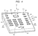
- FIG. 4 is an explanatory diagram illustrating a key arrangement in the input operation portion.
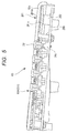
- FIG. 5 is an explanatory diagram illustrating an antenna arrangement in a vertical section of the input operation portion.
- an antenna portion 261 is arranged in a near side position on a panel cover 63c of the input operation portion 63.
- a cross-shaped indicator 261m is printed where the indicator 261m serves as a marker when bringing the mobile terminal (301: FIG. 3 ) into close.
- the indicator 261m is provided in a position where the mobile terminal 301 is positioned to face the antenna portion 261 so that the antenna portion 261 is able to receive a radio signal.
- the antenna 261b which performs wireless communication with the mobile terminal (301: FIG. 3 ), is placed just beneath the indicator 261m of the antenna portion 261.
- the antenna 261b is arranged under the panel cover 63c.
- the antenna portion 261 which is an example of a receiving portion, is provided in the input operation portion 63 so as to be able to receive a radio signal from the mobile terminal 301 by causing the mobile terminal 301, which is an example of a component of transmitting the radio signal, to face the surface of the input operation portion 63.
- LED lamps (211 to 214) for performing various displays are laid out on the panel cover 63c of the input operation portion 63.
- the data display portion 211 displays the action of a job or the presence/absence of a job by turning on/off or blinking the LED lamp.
- the wireless LAN display portion 212 displays a state of the wireless LAN by blinking the LED lamp.
- the error display portion 213 indicates an error by turning on the LED lamp.
- the power display portion 214 displays the ON/OFF state of the power supply by turning on/off the LED lamp.
- the input operation portion 63 which is an example of an operation portion, is provided for a user to perform operations of the image forming apparatus 100.
- On the panel cover 63c of the input operation portion 63 there are laid out setting keys 63a (241 to 243) related to setting input and screen operations and an execution key 63b (an image formation start button 251) for starting an action of the image forming apparatus 100.
- the start key which is an example of the first push button, is arranged in the surface of the input operation portion 63 and is provided to input a signal of starting the image forming action.
- FIG. 6 is a block diagram illustrating a control system of the image forming apparatus.
- a tactile switch 266 is mounted on an operation board 265, where the tactile switch 266 is a switching element for detecting the press of the setting key 63a or the execution key 63b.
- an operation circuit 72 for controlling the image forming apparatus 100 is mounted on the basis of manipulated inputs of the setting key 63a and the execution key 63b as illustrated in FIG. 6 .
- an authentication circuit 71 is also mounted on the operation board 265, where the authentication circuit 71 performs authentication by receiving ratio waves of near field communication output from the mobile terminal 301 ( FIG. 3 ) by using the antenna 261b.
- the antenna 261b is connected to the operation board 265 via a connector 262.
- the liquid crystal screen 62a displays the state of the settings of the image forming portions 1Y, 1M, 1C, and 1K and the action state through the operation circuit 72.
- the operation circuit 72 receives inputs from the touch panel 62b, the setting key 63a, and the execution key 63b.
- a control portion 73 of the image forming apparatus 100 is able to be operated through a personal computer 75 connected by a USB cable, a wired LAN, or a wireless LAN or through the input operation portion 63 provided in the image forming apparatus 100.
- the control portion 73 receives an image forming job including image data by the wired LAN or wireless LAN from the personal computer 75.
- the control portion 73 receives an image forming job including image data by near field communication from the mobile terminal 301.
- the control portion 73 controls the image forming portions 1Y, 1M, 1C, and 1K to perform the image forming job thereof.
- the control portion 73 performs an authentication action for confirming the authority to use the image forming apparatus 100 with the mobile terminal 301 prior to receiving the image forming job.
- authentication data is stored in the authentication circuit 71 through the antenna 261b from the mobile terminal 301. If an authentication item of the stored authentication data matches an authentication item of the image forming apparatus 100, the authentication circuit 71 authenticates the mobile terminal 301 and transmits an input permit signal to the operation circuit 72.
- various settings related to image forming conditions are transmitted from the mobile terminal 301 to the antenna 261b and then the various settings are input to the control portion 73 through the operation circuit 72, and are automatically set. This removes the burden of performing manual setting through the operation portion 61.
- the authentication circuit 71 transmits data of the image forming job transmitted from the mobile terminal 301 to the operation circuit 72 and then the operation circuit 72 forwards the data to the control portion 73.
- the control portion 73 holds the data of the setting contents and of the image forming job and then outputs action commands to respective portions of the image forming apparatus 100.
- a key switch is arranged on the panel cover 63c so that a user is able to operate the input operation portion 63 fluently without confusion.
- the execution key 63b which is pressed after the various settings are completed, is arranged at the lower right of the input operation portion 63.
- the stop key is for use in stopping the image forming action and differs from a power key for turning on or off the power supply.
- the input operation portion 63 and the antenna 261b need to be arranged so as to be close to each other in order to ensure that the user who holds the authentication medium is the same as the user who operates the input operation portion 63.
- the authentication circuit 71 it is possible to provide the authentication circuit 71 on a board other than the operation board 265, it is preferable that the distance between the authentication circuit 71 and the operation circuit 72 is shorter. It is also preferable that the number of parts is less. Therefore, the antenna 261b is disposed close to the operation board 265.
- the antenna 261b is arranged in the nearest position on the near side of the input operation portion 63 and the authentication circuit 71 is provided in the vicinity of the operation circuit 72 on the operation board 265. Therefore, the antenna 261b is provided close to the setting key 63a and the execution key 63b to transmit or receive a radio signal to or from the mobile terminal 301 held with fingers.
- FIG. 7 is a flowchart of authentication control.
- the image forming apparatus 100 has three lines of command for starting a printing action.
- the first line of command is in a case of using a USB cable, a wired LAN, or a wireless LAN.
- An image forming job is transmitted from a personal computer 75 connected via the USB cable, the wired LAN, or the wireless LAN.
- the control portion 73 Upon receiving the image forming job from the personal computer 75 (S101), the control portion 73 activates the image forming portions 1Y, 1M, 1C, and 1K to start the printing action (S105).
- the second line of command is in a case of manually starting a copy process by performing various settings on the liquid crystal screen 62a.
- a user performs required settings by operating a setting key 63a of the operation portion 61 and a virtual key displayed on the liquid crystal screen 62a (S102). Thereafter, the user presses a virtual start key displayed on the liquid crystal screen 62a with a finger (S103). Thereby, the control portion 73 activates the image forming portions 1Y, 1M, 1C, and 1K to perform the printing action (S105).
- the third line of command is in a case of transmitting an image forming job such as photographic printing or the like from the mobile terminal (smartphone) 301.
- the antenna 261b and the authentication circuit 71 automatically detect the mobile terminal 301 by near field communication, and thereby authentication of the authority to use the image forming apparatus 100 is performed (S104).
- control portion 73 causes the mobile terminal 301 to transmit setting data and image forming job data and stores the setting data and image forming job data to perform the printing action (S105).
- control portion 73 determines whether or not the stop key 251 is pressed (S106).
- the control portion 73 stops the printing action (S108). This function is provided for the reason of avoiding unnecessary printing in the case of making a mistake in the number of prints or the like.
- control portion 73 stops the printing action (S108).
- the user's thumb 311a, forefinger not illustrated, middle finger 311c, annular finger 311d, and little finger 311e are protruding from the mobile terminal 301 toward the input operation portion 63 side.
- the mobile terminal 301 is able to be authenticated by being brought close to the antenna portion 261 up to approx. 10 cm apart therefrom.
- the user might bring the mobile terminal 301 closer to the antenna portion 261 in some cases.
- the user might press the mobile terminal 301 against the input operation portion 63.
- the mobile terminal 301 or any of the user's fingers 311 is likely to touch or press a key of the numeric keypad 231 or the stop key 251 by mistake.
- the numeric keypad 231 includes the setting keys 63a which is only used to input the settings and do not immediately affect the action of the image forming apparatus 100. Besides the numeric keypad 231, the home key 221, the reset key 222, the back key 223, the power saving key 225, the status confirmation key 226, the keys of the numeric keypad 231, the authentication key 241, the clear key 242, and the counter key 243 are classified into the setting keys 63a. If the power saving key 225 is pressed during printing action, the input thereof is validated after the completion of the printing action, by which the state of the image forming apparatus 100 is changed. Therefore, the power saving key 225 is classified into the setting key 63a.
- the execution key 63b (251) immediately affects the action of the image forming apparatus 100 in the case of misoperation. Specifically, if the stop key 251 is erroneously operated, the image forming apparatus 100 stops the reception of the print data and of the action command (job) or stops the image forming job under execution in the image forming apparatus 100 (YES in S106: FIG. 7 ). Moreover, depending on a program for the image forming apparatus 100, an input of the execution key 63b may cause a display related to the image forming action on the display portion in some cases, though not directly affecting the image forming action immediately. Even in the case of not directly affecting the image forming action, an action causing a new situation related to the image forming action is not desirable for a user.
- the height of the pressed surface is made different between the setting key and the execution key. At least the central portion of the stop key 251 is located at a position recessed from the surface of the input operation portion 63. Similarly, in the embodiment having the start key, at least the central portion of the start key is located at a position recessed from the surface of the input operation portion 63.
- FIG. 8 is a sectional view of the input operation portion according to the first embodiment.
- each key of the numeric keypad 231 and the stop key 251 are biased against the operation panel cover 63c with coil springs 68 arranged between each key of the numeric keypad 231 and the operation board 265 and between the stop key 251 and the operation board 265. Therefore, each key of the numeric keypad 231 and the stop key 251 are each held with a fixed gap from the tactile switch 266 mounted on the operation board 265.
- the gap is closed and then the tactile switch 266 is pressed a predetermined distance. Thereby, the output of the tactile switch 266 is inverted and the input of the key of the numeric keypad 231 or the stop key 251 is validated.
- the pressed surface of any key of the numeric keypad 231 has an outer peripheral portion around the central portion thereof protruding more than the central portion in the opposite direction to the pressing direction.
- the pressed surface of the stop key 251 has an outer peripheral portion around the central portion thereof protruding more than the central portion in the opposite direction to the pressing direction.
- the outer peripheral portion of the pressed surface of the key of the numeric keypad 231 protrudes more than the outer peripheral portion of the pressed surface of the stop key 251 in the opposite direction to the pressing direction, by which misoperation of the stop key 251 less easily occurs than the keys of the numeric keypad 231.
- any key of the numeric keypad 231 has a key height set so that the highest convex portion 231b protrudes more than the surface of the operation panel cover 63c.
- the key of the numeric keypad 231 can be pressed without being obstructed by the panel cover 63c, and therefore it is easy to validate the input of the key of the numeric keypad 231.
- the highest convex portion 251b of the stop key 251 is lower than the convex portion 231b of the key of the numeric keypad 231. This prevents the input of a key from being validated even if the stop key 251 is pressed by mistake with the mobile terminal 301 or any of the user's fingers 311 when the user brings the mobile terminal 301 close to the antenna portion 261.
- the convex portion of the execution key 63b (stop key 251) is substantially flush with or slightly lower than the surface of the operation panel cover 63c. Therefore, even if the user's fingers 311 come close to the stop key 251 for performing authentication by bringing the mobile terminal 301 close to the antenna portion 261, any of the user's fingers 311 abuts against the operation panel cover 63c. Therefore, the input of the execution key 63b is not easily validated.
- the key input is invalidated unless the input mode of the setting key 63a has been entered operationally. Even if the input mode has been entered, the operation of the setting key 63a is validated only after pressing "a decision key displayed on the liquid crystal screen 62a" which is used to decide an input with the input contents displayed on the liquid crystal screen 62a after the operation of the setting key 63a, and therefore the pressing by mistake does not directly lead to a problem.
- the execution key 63b is configured to have a height lower than other setting keys 63a. Therefore, in order to validate the input of the execution key 63b, it is necessary to push the execution key 63b more deeply than other setting keys 63a. Therefore, even if any of the user's fingers 311 touches the execution key 63b by mistake when the user brings the mobile terminal 301 close to the antenna portion 261 for authentication, it is less likely to validate the input of the execution key 63b which leads to a misoperation of the image forming apparatus 100.
- the execution key 63b is configured to have the same height as or lower height than the surface of the operation panel cover 63c. Therefore, only a touch of any of the user's fingers 311 by mistake does not cause the execution key 63b to be depressed so deeply as to cause the inversion of the output because the depression is obstructed by the operation panel cover 63c, thereby decreasing the likelihood of causing a misoperation related to the image forming action of the image forming apparatus 100 which is caused by a validated input of the execution key 63b.
- a first pressed surface in a non-pressed state protrudes more than a second pressed surface in a non-pressed state in the opposite direction to the pressing direction. Therefore, the stop key 251 is less likely to interfere with the mobile terminal 301 and the fingers than the keys of the numeric keypad 231 and thus is more unlikely to be erroneously operated than the keys of the numeric keypad 231.
- the first pressed surface in the non-pressed state is higher than the second pressed surface in the non-pressed state in the opposite direction to the pressing direction regarding the height from the surface of the operation panel cover 63c. For this reason, the stop key 251 is supported by the operation panel cover 63c and is less likely to be operated by mistake with the mobile terminal 301 or fingers than the keys of the numeric keypad 231.
- the first pressed surface in the non-pressed state protrudes more than the surface of the operation panel cover 63c and the second pressed surface in the non-pressed state is recessed from the surface of the operation panel cover 63c. Therefore, the stop key 251 is less likely to interfere with the mobile terminal 301 and the fingers than the keys of the numeric keypad 231 and is less likely to be operated by mistake than the keys of the numeric keypad 231.
- a difference in the position in the pressing direction between the first pressed surface in the non-pressed state and the second pressed surface in the non-pressed state is equal to or longer than 0.5 mm and shorter than 1 mm. Accordingly, a misoperation of the stop key 251 can be avoided, while a difference in the height between the stop key 251 and the keys of the numeric keypad 231 is inconspicuous, thus providing an image forming apparatus excellent in design.
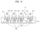
- FIG. 9 is a sectional view of an input operation portion according to a second embodiment.
- the height of the pressed surface is different between the keys of the numeric keypad 231 and the stop key 251.
- a keystroke is different between the keys of the numeric keypad 231 and the stop key 251.
- the stop key 251 has a longer keystroke than the keystroke of each key of the numeric keypad 231, where the keystroke is a depressed distance to the input of a signal.
- each key of the numeric keypad 231 and the stop key 251 are biased against the operation panel cover 63c with coil springs 68 arranged between each key of the numeric keypad 231 and the operation board 265 and between the stop key 251 and the operation board 265. Therefore, each key of the numeric keypad 231 and the stop key 251 are held with a fixed gap from the tactile switch 266 mounted on the operation board 265. If any key of the numeric keypad 231 or the stop key 251 is pressed downward, the gap is closed and then the tactile switch 266 is pressed by a predetermined distance. Thereby, the output of the tactile switch 266 is inverted and the input of the key of the numeric keypad 231 or the stop key 251 is validated.
- the convex portion 231b of any key of the numeric keypad 231 has substantially the same height as the convex portion 251b of the stop key 251.
- the convex portion 231b of any key of the numeric keypad 231 has the same amount of protrusion from the surface of the operation panel cover 63c as the convex portion 251b of the stop key 251.
- a gap 231c between the numeric keypad 231 and the tactile switch 266 is smaller than a gap 251c between the stop key 251 and the tactile switch 266.
- the keys of the numeric keypad 231 each have a smaller push-in amount (keystroke) up to the height at which a key input is validated than the stop key 251. Therefore, the input of the stop key 251 is less easily validated than the input of the numeric keypad 231.
- the stop key 251 has a large gap 251c, thereby increasing the depression amount (keystroke) up to the height at which the operation of the stop key 251 is validated from the non-pressed state.
- the keystroke from the depression of the execution key 63b is started until the input of the execution key 63b is validated is larger than the similar keystroke of the setting key 63a.
- the keystroke of the setting key 63a which is a moving distance of the first pressed surface from the non-pressed state of the setting key 63a to an output inversion, is smaller than the keystroke of the execution key 63b, which is a moving distance of the second pressed surface from the non-pressed state of the execution key 63b to an output inversion.
- a user When performing authentication by bringing the mobile terminal 301 close to the antenna portion 261, a user is able to move his/her finger away before the input of the execution key is validated at the time when the user feels a touch of the key with his/her finger, thereby preventing a misoperation of the image forming apparatus 100. Even if any of the user's fingers 311 touches the stop key 251 by mistake when the user performs authentication by bringing the mobile terminal 301 close to the antenna portion 261, the input of the execution key 63b is less likely to be validated.
- the stop key 251 is provided with a longer distance and time before the validation of the key input than each key of the numeric keypad 231, thereby preventing a misoperation on the image forming apparatus 100.
- the gap 251c between the execution key 63b such as the stop key 251 and the tactile switch 266 is large in comparison with the gap 231c between the setting key 63a such as any key of the numeric keypad 231 and the tactile switch 266. Therefore, it is possible to use a common tactile switch 266 between the setting key 63a and the execution key 63b.
- a method of increasing the pressing distance (keystroke) up to the height at which the key input on the execution key 63b is validated is not limited to the method of increasing the gap 251c.
- the keystroke of the tactile switch 266 for the execution key 63b may be larger than the keystroke of the tactile switch 266 for the setting key 63a.
- the gap 231c and the gap 251c may be set so as to be equal and then the tactile switch 266 just under the execution key 63b may be of the type having a larger keystroke than the tactile switch 266 just under the setting key 63a.
- the keystroke of the start key is also made larger than the keystroke of each key of the numeric keypad 231.
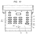
- FIG. 10 is a top view of an input operation portion according to a third embodiment.
- the execution key is made less likely to be depressed by employing different heights between the setting key and the execution key.
- a rib 63d which is an example of a protrusion, is provided on the surface of the input operation portion 63 adjacent to the stop key 251 on the side where the mobile terminal 301 is brought close to the antenna portion, so that the stop key 251 is less likely to be depressed.
- the keys of the numeric keypad 231 each have the same height as the stop key 251.
- the keystroke is also the same between each key of the numeric keypad 231 and the stop key 251.
- the rib 63d as a misoperation prevention wall which is adjacent to the stop key 251 on the operation panel cover 63c.
- the rib 63d is provided adjacent to the sides (the front side and the left side) of the stop key 251 facing the mobile terminal 301 which moves toward the antenna portion 261.
- the rib 63d is provided in such a way as to protect two upright sides (the front side and the left side) of the stop key 251 on the antenna portion 261 side.
- a rib similar to the rib 63d is provided on the surface of the input operation portion 63 adjacent to the start key on the side where the mobile terminal 301 is brought close to the antenna portion.
- the height of the rib 63d is higher than at least the key height just before the validation of the key input caused by depressing the stop key 251 from the non-pressed state. Therefore, even if the user touches the stop key 251 by mistake, the user is not able to further depress the stop key 251 because any of user's fingers 311 touches the rib 63d before the input of the stop key 251 is validated. If the user moves the finger 311 away from the rib 63d at the time when the user feels the touch of the rib 63d with the finger 311, the input of the stop key 251 is not validated.
- a user's finger touches the rib 63d before the user touches the execution key 63b or, even in the case where the user touches the execution key 63b, before the input of the execution key 63d is validated. Therefore, the user is able to move the finger away from the execution key 63b at the time when the user feels the touch of the rib 63d with the finger.
- the depression itself of the stop key 251 may be prevented by increasing the height of the rib 63d so as to be higher than the maximum height of the stop key 251 in the non-pressed state.
- any of the user's fingers 311 abuts against the rib 63d before the user's finger 311 touches the stop key 251 by mistake, by which the stop key 251 is not depressed.
- the increase in the height of the rib 63d might impair the operability of the stop key 251 and the design quality of the input operation portion 63.
- the entire periphery of the stop key 251 may be enclosed by a wall-like rib.
- the user When attempting to intentionally operate the stop key 251 for the purpose of stopping the image formation, however, the user occasionally fails to depress the stop key 251 because the rib lies in the way. Therefore, as illustrated in FIG. 10 , it is also preferable to provide the rib 63d only on the antenna portion 261 side of the periphery of the stop key 251.
- the third embodiment may be combined with the first or second embodiment.
- the height of the stop key 251 may be lower than the height of each key of the numeric keypad 231 and the keystroke of the stop key 251 may be larger than the keystroke of each key of the numeric keypad 231.
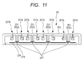
- FIG. 11 is an explanatory diagram illustrating another example of the structure of a key switch. As illustrated in FIG. 11 , the stop key 251 and each key of the numeric keypad 231 may be each formed of a conductive rubber sheet 276 connected to the ground potential and a switch contact 277 provided on a switch board 278.
- the communication components can be implemented by various types of devices that can be authenticated by wireless communication, such as a digital camera, a video camera, a mobile phone, a smartphone, a tablet terminal, a wireless communication unit, a personal digital assistant (PDA), a remote-control unit, and the like.
- the authentication medium may be implemented by a card medium not having a power supply using an IC tag.
- the image forming portion capable of forming an image on a recording medium is not limited to one in the electrophotographic image forming apparatus. Even an image forming apparatus using another recording system or printing system such as an inkjet recording system can implement the present invention.
- the execution key 63b is only the stop key 251.
- the present invention can be implemented by a complex machine having a copier, a facsimile machine, and a scanner function.
- the start key may be located next to the stop key 251 in the vicinity thereof (for example, to the left), though the start key is displayed on the liquid crystal screen 62a in the first, second, and third embodiments.
- two keys, namely the added start key and the stop key 251 are execution keys 63b.
- the operation portion 61 is vertically long and therefore there are arranged the liquid crystal screen 62a which is a display portion, the input operation portion 63, and the antenna portion 261, which performs authentication, in sequence from the rear side.
- the operation portion 61 may be horizontally long. In this case, from the viewpoint of human engineering, it is preferable to arrange the liquid crystal screen 62a, the input operation portion 63, and the antenna portion 261 in order thereof from the left. Also in this case, the execution key 63b is arranged nearest to the antenna portion 261 in the same manner.
- the first, second, and third embodiments may be singly implemented or two or three of the embodiments may be implemented in combination.
- An image forming apparatus includes: an image forming portion capable of forming an image on a recording medium; an operation portion for performing an operation of the image forming apparatus; a push button which is arranged in a surface of the operation portion, and with which a signal of stopping an image forming action performed by the image forming portion is input; a receiving portion provided in the operation portion so as to be able to receive a radio signal from a communication component by placing the communication component transmitting the radio signal so as to face the receiving portion; and at least a central portion of the push button located at a position recessed from the surface of the operation portion.
Landscapes
- Engineering & Computer Science (AREA)
- Multimedia (AREA)
- Signal Processing (AREA)
- Physics & Mathematics (AREA)
- General Physics & Mathematics (AREA)
- Human Computer Interaction (AREA)
- Microelectronics & Electronic Packaging (AREA)
- Theoretical Computer Science (AREA)
- Astronomy & Astrophysics (AREA)
- Computer Networks & Wireless Communication (AREA)
- General Engineering & Computer Science (AREA)
- Accessory Devices And Overall Control Thereof (AREA)
- Facsimiles In General (AREA)
- Electrophotography Configuration And Component (AREA)
- Control Or Security For Electrophotography (AREA)
- Input From Keyboards Or The Like (AREA)
Abstract
Description
- The present invention relates to an image forming apparatus such as a printer, facsimile machine, or copier.
- An image forming apparatus which forms an image such as a character, a picture, or a photograph on a recording medium is widely used. In a surface of an operation portion of the image forming apparatus, there is arranged a push button for use in inputting a signal for stopping (or starting) an image forming action.
- In the image forming apparatus, there has been developed a technique of inputting print data by using near field communication.
Japanese Patent Application Laid-Open No. 2014-157532 - In the case of inputting print data into an image forming apparatus by using near field communication, a user needs to be authenticated by the image forming apparatus while holding an equipment body, from which the print data is to be transmitted, or an authentication medium such as an IC card close to a receiving portion of the image forming apparatus. As disclosed in
Japanese Patent Application Laid-Open No. 2014-157532 - Therefore, when bringing the equipment body or the authentication medium close to the receiving portion, the user might push the push button related to the start or stop of an image forming action by mistake, which leads to an input of an instruction related to the start or stop of the image forming action unfavorably.
- Therefore, it is an object of the present invention to provide an image forming apparatus capable of reducing opportunities of pushing a push button related to the start or stop of an image forming action even in the case of bringing a communication component close to an operation portion when performing near field communication.
- According to an aspect of the present invention, there is provided an image forming apparatus including: an image forming portion capable of forming an image on a recording medium; an operation portion for performing an operation of the image forming apparatus; a push button which is arranged in a surface of the operation portion, and with which a signal of stopping an image forming action performed by the image forming portion is input; a receiving portion provided in the operation portion so as to be able to receive a radio signal from a communication component by placing the communication component transmitting the radio signal so as to face the receiving portion; and at least a central portion of the push button located at a position recessed from the surface of the operation portion.
- According to another aspect of the present invention, there is provided an image forming apparatus including: an image forming portion capable of forming an image on a recording medium; an operation portion for performing an operation of the image forming apparatus; a push button which is arranged in a surface of the operation portion, and with which a signal of starting an image forming action performed by the image forming portion is input; a receiving portion provided in the operation portion so as to be able to receive a radio signal from a communication component by placing the communication component transmitting the radio signal so as to face the receiving portion; and at least a central portion of the push button located at a position recessed from the surface of the operation portion.
- Further features of the present invention will become apparent from the following description of exemplary embodiments with reference to the attached drawings.
-
-
FIG. 1 is an explanatory diagram illustrating a configuration of an image forming apparatus according to a first embodiment. -
FIG. 2 is a perspective view illustrating an appearance of the image forming apparatus. -
FIG. 3 is an explanatory diagram illustrating an authentication operation using an authentication medium. -
FIG. 4 is an explanatory diagram illustrating a key arrangement in an input operation portion. -
FIG. 5 is an explanatory diagram illustrating an antenna arrangement in a vertical section of the input operation portion. -
FIG. 6 is a block diagram illustrating a control system of the image forming apparatus. -
FIG. 7 is a flowchart of authentication control. -
FIG. 8 is a sectional view of an input operation portion according to the first embodiment. -
FIG. 9 is a sectional view of an input operation portion according to a second embodiment. -
FIG. 10 is a top view of an input operation portion according to a third embodiment. -
FIG. 11 is an explanatory diagram illustrating another structure of a key switch. - Embodiments of the present invention will now be described in detail in accordance with the drawings.
-
FIG. 1 is an explanatory diagram illustrating a configuration of an image forming apparatus according to a first embodiment. As illustrated inFIG. 1 , animage forming apparatus 100 is an intermediate transfer type full-color laser beam printer which forms an image by an electrophotographic system. -
Image forming portions intermediate transfer belt 18, a secondary transferouter roller 24, and afixing device 30 are able to form an image on a recording medium. Theimage forming portion 1Y forms a yellow toner image on aphotosensitive drum 11 and transfers the toner image onto theintermediate transfer belt 18. Theimage forming portion 1M forms a magenta toner image on thephotosensitive drum 11 and transfers the toner image onto theintermediate transfer belt 18. Theimage forming portions photosensitive drum 11, respectively, and transfer the respective toner images onto theintermediate transfer belt 18. - The four-color toner images transferred to the
intermediate transfer belt 18 are conveyed to a secondary transfer part T2 and then transferred to a sheetS. A cassette 40 accommodates stacked sheets. Afeed roller 22 separates the top sheet S and feeds the sheet S into aregistration roller 23. Theregistration roller 23 corrects the skew of the sheet and feeds the sheet to the secondary transfer part T2 while matching the timing with the toner images on theintermediate transfer belt 18. - The secondary transfer
outer roller 24 is brought into contact with theintermediate transfer belt 18 on the secondary transferinner roller 25 to form the secondary transfer part T2. A DC voltage is applied to the secondary transferouter roller 24, by which the toner images carried on theintermediate transfer belt 18 are transferred to the sheet S. The sheet S to which the toner images are transferred is conveyed to thefixing device 30 and then heated and pressed so that the images are fixed to the sheet S. Thereafter, the sheet S is discharged to adischarge tray 51 by adischarge roller 33. - The
image forming portions image forming portion 1Y will be described here and duplicate description related to theimage forming portions - In the
image forming portion 1Y, acharging roller 12, anexposure device 13, a developing device 14, atransfer roller 15, and adrum cleaning device 16 are arranged around thephotosensitive drum 11. - In the
photosensitive drum 11, a photosensitive layer is formed on the surface of the base of a metal pipe. Thecharging roller 12 electrically charges thephotosensitive drum 11 to a uniform potential due to application of an oscillation voltage to thecharging roller 12, where the oscillation voltage is generated by superposing an AC voltage on a DC voltage. Theexposure device 13 forms an electrostatic latent image on thephotosensitive drum 11 by scanning the photosensitive layer with a laser beam to expose the photosensitive layer. - The developing device 14 develops the electrostatic latent image on the
photosensitive drum 11 to toner images by using a two-component developer. Upon application of a DC voltage to thetransfer roller 15, thetransfer roller 15 transfers the toner images carried on thephotosensitive drum 11 to theintermediate transfer belt 18. Thedrum cleaning device 16 frictionally slides the cleaning blade on thephotosensitive drum 11 to collect transfer residual toner on thephotosensitive drum 11. -
FIG. 2 is a perspective view illustrating an appearance of the image forming apparatus. As illustrated inFIG. 2 , theimage forming apparatus 100 includes thecassette 40 for accommodating sheets in the lower part. In the upper part of theimage forming apparatus 100, theimage forming apparatus 100 includes thedischarge tray 51 for stacking sheets on which the images are formed. - An
operation portion 61 is provided beside thedischarge tray 51 on the upper surface of theimage forming apparatus 100. In theoperation portion 61, aninput operation portion 63 for performing various inputs is arranged on the near side of aliquid crystal screen 62a for performing various displays. Theliquid crystal screen 62a displays the state of the power supply of theimage forming apparatus 100, the presence/absence of a job, an error condition or the like. - On the surface of the
liquid crystal screen 62a, atransparent touch panel 62b is provided. The setting contents such as the number of processed sheets, the kind of sheet, temperature, humidity, and the like displayed on theliquid crystal screen 62a are able to be changed by atouch panel 62b through icons displayed on theliquid crystal screen 62a. - Through the
liquid crystal screen 62a where thetouch panel 62b is provided, operations and settings for a printer are able to be performed such as network settings, job deletion, or various settings. -
FIG. 3 is an explanatory diagram illustrating an authentication operation performed with a mobile terminal brought close to the input operation portion. As illustrated inFIG. 3 , theimage forming apparatus 100 is able to perform wireless communication through near field communication (NFC) between a mobile terminal (communication component) 301 and anantenna 261b. Themobile terminal 301 receives an image forming job including image data and various types of setting data through near field communication. Theimage forming apparatus 100 is able to perform remote control through near field communication by using themobile terminal 301. - The
image forming apparatus 100 has an authentication function using near field communication so as to be able to identify an individual from the viewpoint of security to simplify the operation so that the operation can be conveniently performed. - In the near field communication, the communication distance is limited to 10 cm or so and therefore the authentication of the
mobile terminal 301 is performed with themobile terminal 301 "held over" theinput operation portion 63. After the authentication, data transfer of the image forming job is performed from themobile terminal 301 to theimage forming apparatus 100. The data of the image forming job is data for one printing unit, and includes data of one or more images, printing condition specification data, and a print command. -
FIG. 4 is an explanatory diagram illustrating a key arrangement in the input operation portion.FIG. 5 is an explanatory diagram illustrating an antenna arrangement in a vertical section of the input operation portion. - As illustrated in
FIG. 4 , anantenna portion 261 is arranged in a near side position on apanel cover 63c of theinput operation portion 63. On thepanel cover 63c, across-shaped indicator 261m is printed where theindicator 261m serves as a marker when bringing the mobile terminal (301:FIG. 3 ) into close. In theinput operation portion 63, theindicator 261m is provided in a position where themobile terminal 301 is positioned to face theantenna portion 261 so that theantenna portion 261 is able to receive a radio signal. - As illustrated in
FIG. 5 , theantenna 261b, which performs wireless communication with the mobile terminal (301:FIG. 3 ), is placed just beneath theindicator 261m of theantenna portion 261. Theantenna 261b is arranged under thepanel cover 63c. Theantenna portion 261, which is an example of a receiving portion, is provided in theinput operation portion 63 so as to be able to receive a radio signal from themobile terminal 301 by causing themobile terminal 301, which is an example of a component of transmitting the radio signal, to face the surface of theinput operation portion 63. - As illustrated in
FIG. 4 , LED lamps (211 to 214) for performing various displays are laid out on thepanel cover 63c of theinput operation portion 63. The data displayportion 211 displays the action of a job or the presence/absence of a job by turning on/off or blinking the LED lamp. The wirelessLAN display portion 212 displays a state of the wireless LAN by blinking the LED lamp. Theerror display portion 213 indicates an error by turning on the LED lamp. Thepower display portion 214 displays the ON/OFF state of the power supply by turning on/off the LED lamp. - As illustrated in
FIG. 4 , theinput operation portion 63, which is an example of an operation portion, is provided for a user to perform operations of theimage forming apparatus 100. On thepanel cover 63c of theinput operation portion 63, there are laid out settingkeys 63a (241 to 243) related to setting input and screen operations and anexecution key 63b (an image formation start button 251) for starting an action of theimage forming apparatus 100. - (1) A
home key 221 is pressed to return the display of theliquid crystal screen 62a to the home screen. - (2) A
reset key 222 is pressed to reset the set contents displayed on theliquid crystal screen 62a to default values. - (3) A
back key 223 is pressed to return the display of theliquid crystal screen 62a to the screen which is one level upper in the hierarchy. - (4) A
power saving key 225 is pressed to shift to a power saving mode and is pressed again to recover from the power saving mode. - (5) A
status confirmation key 226 is pressed to display a print status and a report output status on theliquid crystal screen 62a for confirmation. - (6) Any key of the
numeric keypad 231 is pressed to input a numeral, a symbol, or a character in a cursor position displayed on theliquid crystal screen 62a. The key of thenumeric keypad 231, which is an example of a second push button, is a button for inputting a numerical value and therefore is provided to input a signal for an operation other than the stop and start of the image forming action. - (7) An
authentication key 241 is pressed to cause the display of theliquid crystal screen 62a to enter a password mode for inputting a password number or to exit the password mode. - (8) A
clear key 242 is pressed to clear the numeral or character in the cursor position. - (9) A
counter key 243 is pressed to display counter information, which contains a record of how many sheets theimage forming apparatus 100 printed, on theliquid crystal screen 62a. - (10) When settings are made on the
liquid crystal screen 62a, a virtual setting key, not illustrated, is displayed on theliquid crystal screen 62a. Pressing the virtual setting key with a finger activates thetouch panel 62b to generate a required input signal. - (11) When manual start is performed on the
liquid crystal screen 62a, a virtual start key, not illustrated, is displayed on theliquid crystal screen 62a. Pressing the virtual start key with a finger activates thetouch panel 62b to start the image formation. - (12) A
stop key 251 aborts a job and stops the printing action of theimage forming apparatus 100. Thestop key 251, which is an example of a first push button, is arranged in the surface of theinput operation portion 63 and is provided to input a signal of stopping the image forming action. - In an embodiment having a start key, the start key, which is an example of the first push button, is arranged in the surface of the
input operation portion 63 and is provided to input a signal of starting the image forming action. -
FIG. 6 is a block diagram illustrating a control system of the image forming apparatus. As illustrated inFIG. 5 , atactile switch 266 is mounted on anoperation board 265, where thetactile switch 266 is a switching element for detecting the press of the setting key 63a or theexecution key 63b. On theoperation board 265, anoperation circuit 72 for controlling theimage forming apparatus 100 is mounted on the basis of manipulated inputs of the setting key 63a and the execution key 63b as illustrated inFIG. 6 . - As illustrated in
FIG. 6 , anauthentication circuit 71 is also mounted on theoperation board 265, where theauthentication circuit 71 performs authentication by receiving ratio waves of near field communication output from the mobile terminal 301 (FIG. 3 ) by using theantenna 261b. Theantenna 261b is connected to theoperation board 265 via aconnector 262. - As illustrated in
FIG. 6 , theliquid crystal screen 62a displays the state of the settings of theimage forming portions operation circuit 72. Theoperation circuit 72 receives inputs from thetouch panel 62b, the setting key 63a, and theexecution key 63b. - A
control portion 73 of theimage forming apparatus 100 is able to be operated through apersonal computer 75 connected by a USB cable, a wired LAN, or a wireless LAN or through theinput operation portion 63 provided in theimage forming apparatus 100. - The
control portion 73 receives an image forming job including image data by the wired LAN or wireless LAN from thepersonal computer 75. Thecontrol portion 73 receives an image forming job including image data by near field communication from themobile terminal 301. Thecontrol portion 73 controls theimage forming portions - The
control portion 73 performs an authentication action for confirming the authority to use theimage forming apparatus 100 with themobile terminal 301 prior to receiving the image forming job. - If the
mobile terminal 301 is held close to theantenna 261b as illustrated inFIG. 3 , authentication data is stored in theauthentication circuit 71 through theantenna 261b from themobile terminal 301. If an authentication item of the stored authentication data matches an authentication item of theimage forming apparatus 100, theauthentication circuit 71 authenticates themobile terminal 301 and transmits an input permit signal to theoperation circuit 72. - If the
mobile terminal 301 is authenticated, various settings related to image forming conditions are transmitted from themobile terminal 301 to theantenna 261b and then the various settings are input to thecontrol portion 73 through theoperation circuit 72, and are automatically set. This removes the burden of performing manual setting through theoperation portion 61. - Subsequently, the
authentication circuit 71 transmits data of the image forming job transmitted from themobile terminal 301 to theoperation circuit 72 and then theoperation circuit 72 forwards the data to thecontrol portion 73. Thecontrol portion 73 holds the data of the setting contents and of the image forming job and then outputs action commands to respective portions of theimage forming apparatus 100. - As illustrated in
FIG. 4 , in theinput operation portion 63, a key switch is arranged on thepanel cover 63c so that a user is able to operate theinput operation portion 63 fluently without confusion. - From the viewpoint of human engineering, it is natural and desirable that a series of key operations are performed from the upper left to the lower right. Therefore, in the
image forming apparatus 100, theexecution key 63b, which is pressed after the various settings are completed, is arranged at the lower right of theinput operation portion 63. The stop key is for use in stopping the image forming action and differs from a power key for turning on or off the power supply. - From the viewpoint of human engineering, the
input operation portion 63 and theantenna 261b need to be arranged so as to be close to each other in order to ensure that the user who holds the authentication medium is the same as the user who operates theinput operation portion 63. Although it is possible to provide theauthentication circuit 71 on a board other than theoperation board 265, it is preferable that the distance between theauthentication circuit 71 and theoperation circuit 72 is shorter. It is also preferable that the number of parts is less. Therefore, theantenna 261b is disposed close to theoperation board 265. - For this reason, in the
image forming apparatus 100, theantenna 261b is arranged in the nearest position on the near side of theinput operation portion 63 and theauthentication circuit 71 is provided in the vicinity of theoperation circuit 72 on theoperation board 265. Therefore, theantenna 261b is provided close to the setting key 63a and the execution key 63b to transmit or receive a radio signal to or from themobile terminal 301 held with fingers. -
FIG. 7 is a flowchart of authentication control. Theimage forming apparatus 100 has three lines of command for starting a printing action. - As illustrated in
FIG. 6 , the first line of command is in a case of using a USB cable, a wired LAN, or a wireless LAN. An image forming job is transmitted from apersonal computer 75 connected via the USB cable, the wired LAN, or the wireless LAN. Upon receiving the image forming job from the personal computer 75 (S101), thecontrol portion 73 activates theimage forming portions - The second line of command is in a case of manually starting a copy process by performing various settings on the
liquid crystal screen 62a. A user performs required settings by operating a setting key 63a of theoperation portion 61 and a virtual key displayed on theliquid crystal screen 62a (S102). Thereafter, the user presses a virtual start key displayed on theliquid crystal screen 62a with a finger (S103). Thereby, thecontrol portion 73 activates theimage forming portions - The third line of command is in a case of transmitting an image forming job such as photographic printing or the like from the mobile terminal (smartphone) 301. When the
mobile terminal 301 is brought close to theoperation portion 61, theantenna 261b and theauthentication circuit 71 automatically detect themobile terminal 301 by near field communication, and thereby authentication of the authority to use theimage forming apparatus 100 is performed (S104). - If the authentication is completed successfully (YES in S104), the
control portion 73 causes themobile terminal 301 to transmit setting data and image forming job data and stores the setting data and image forming job data to perform the printing action (S105). - Upon starting the printing action (S105), the
control portion 73 determines whether or not thestop key 251 is pressed (S106). - If the
stop key 251 is pressed after starting the printing action, thecontrol portion 73 stops the printing action (S108). This function is provided for the reason of avoiding unnecessary printing in the case of making a mistake in the number of prints or the like. - If the printing action is completed (YES in S107) without pressing the stop key 251 (NO in S106), the
control portion 73 stops the printing action (S108). - As illustrated in
FIG. 3 , when the user holds themobile terminal 301 with his/herfingers 311 for authentication, the user'sthumb 311a, forefinger not illustrated,middle finger 311c,annular finger 311d, andlittle finger 311e are protruding from themobile terminal 301 toward theinput operation portion 63 side. - The
mobile terminal 301 is able to be authenticated by being brought close to theantenna portion 261 up to approx. 10 cm apart therefrom. Depending on the state of theantenna 261b or on the performance of themobile terminal 301, however, the user might bring themobile terminal 301 closer to theantenna portion 261 in some cases. In an extreme case, the user might press themobile terminal 301 against theinput operation portion 63. In such a case, themobile terminal 301 or any of the user'sfingers 311 is likely to touch or press a key of thenumeric keypad 231 or thestop key 251 by mistake. - In this case, the setting
keys 63a (221 to 243) do not immediately affect the action of theimage forming apparatus 100 even in the case of misoperation. Thenumeric keypad 231 includes the settingkeys 63a which is only used to input the settings and do not immediately affect the action of theimage forming apparatus 100. Besides thenumeric keypad 231, thehome key 221, thereset key 222, theback key 223, thepower saving key 225, thestatus confirmation key 226, the keys of thenumeric keypad 231, theauthentication key 241, theclear key 242, and thecounter key 243 are classified into the settingkeys 63a. If thepower saving key 225 is pressed during printing action, the input thereof is validated after the completion of the printing action, by which the state of theimage forming apparatus 100 is changed. Therefore, thepower saving key 225 is classified into the setting key 63a. - The
execution key 63b (251) immediately affects the action of theimage forming apparatus 100 in the case of misoperation. Specifically, if thestop key 251 is erroneously operated, theimage forming apparatus 100 stops the reception of the print data and of the action command (job) or stops the image forming job under execution in the image forming apparatus 100 (YES in S106:FIG. 7 ). Moreover, depending on a program for theimage forming apparatus 100, an input of theexecution key 63b may cause a display related to the image forming action on the display portion in some cases, though not directly affecting the image forming action immediately. Even in the case of not directly affecting the image forming action, an action causing a new situation related to the image forming action is not desirable for a user. - In the first embodiment, the height of the pressed surface is made different between the setting key and the execution key. At least the central portion of the
stop key 251 is located at a position recessed from the surface of theinput operation portion 63. Similarly, in the embodiment having the start key, at least the central portion of the start key is located at a position recessed from the surface of theinput operation portion 63. -
FIG. 8 is a sectional view of the input operation portion according to the first embodiment. As illustrated inFIG. 8 , each key of thenumeric keypad 231 and thestop key 251 are biased against theoperation panel cover 63c withcoil springs 68 arranged between each key of thenumeric keypad 231 and theoperation board 265 and between thestop key 251 and theoperation board 265. Therefore, each key of thenumeric keypad 231 and thestop key 251 are each held with a fixed gap from thetactile switch 266 mounted on theoperation board 265. - If any key of the
numeric keypad 231 or thestop key 251 is pressed downward, the gap is closed and then thetactile switch 266 is pressed a predetermined distance. Thereby, the output of thetactile switch 266 is inverted and the input of the key of thenumeric keypad 231 or thestop key 251 is validated. - In the first embodiment, the pressed surface of any key of the
numeric keypad 231 has an outer peripheral portion around the central portion thereof protruding more than the central portion in the opposite direction to the pressing direction. The pressed surface of thestop key 251 has an outer peripheral portion around the central portion thereof protruding more than the central portion in the opposite direction to the pressing direction. Also in this case, the outer peripheral portion of the pressed surface of the key of thenumeric keypad 231 protrudes more than the outer peripheral portion of the pressed surface of thestop key 251 in the opposite direction to the pressing direction, by which misoperation of thestop key 251 less easily occurs than the keys of thenumeric keypad 231. - Any key of the
numeric keypad 231 has a key height set so that the highestconvex portion 231b protrudes more than the surface of theoperation panel cover 63c. The key of thenumeric keypad 231 can be pressed without being obstructed by thepanel cover 63c, and therefore it is easy to validate the input of the key of thenumeric keypad 231. On the other hand, the highestconvex portion 251b of thestop key 251 is lower than theconvex portion 231b of the key of thenumeric keypad 231. This prevents the input of a key from being validated even if thestop key 251 is pressed by mistake with themobile terminal 301 or any of the user'sfingers 311 when the user brings themobile terminal 301 close to theantenna portion 261. - Furthermore, the convex portion of the
execution key 63b (stop key 251) is substantially flush with or slightly lower than the surface of theoperation panel cover 63c. Thereby, even if the user'sfingers 311 come close to thestop key 251 for performing authentication by bringing themobile terminal 301 close to theantenna portion 261, any of the user'sfingers 311 abuts against theoperation panel cover 63c. Therefore, the input of theexecution key 63b is not easily validated. - The user presses the center of the key when intentionally pressing the
stop key 251, and therefore it is not difficult to validate the input of thestop key 251. - In the case where the setting key 63a such as a key of the
numeric keypad 231 is pressed by mistake, the key input is invalidated unless the input mode of the setting key 63a has been entered operationally. Even if the input mode has been entered, the operation of the setting key 63a is validated only after pressing "a decision key displayed on theliquid crystal screen 62a" which is used to decide an input with the input contents displayed on theliquid crystal screen 62a after the operation of the setting key 63a, and therefore the pressing by mistake does not directly lead to a problem. - In the first embodiment, the
execution key 63b is configured to have a height lower thanother setting keys 63a. Therefore, in order to validate the input of theexecution key 63b, it is necessary to push theexecution key 63b more deeply thanother setting keys 63a. Therefore, even if any of the user'sfingers 311 touches theexecution key 63b by mistake when the user brings themobile terminal 301 close to theantenna portion 261 for authentication, it is less likely to validate the input of theexecution key 63b which leads to a misoperation of theimage forming apparatus 100. - In the first embodiment, the
execution key 63b is configured to have the same height as or lower height than the surface of theoperation panel cover 63c. Therefore, only a touch of any of the user'sfingers 311 by mistake does not cause the execution key 63b to be depressed so deeply as to cause the inversion of the output because the depression is obstructed by theoperation panel cover 63c, thereby decreasing the likelihood of causing a misoperation related to the image forming action of theimage forming apparatus 100 which is caused by a validated input of theexecution key 63b. - In the first embodiment, a first pressed surface in a non-pressed state protrudes more than a second pressed surface in a non-pressed state in the opposite direction to the pressing direction. Therefore, the
stop key 251 is less likely to interfere with themobile terminal 301 and the fingers than the keys of thenumeric keypad 231 and thus is more unlikely to be erroneously operated than the keys of thenumeric keypad 231. - In the first embodiment, the first pressed surface in the non-pressed state is higher than the second pressed surface in the non-pressed state in the opposite direction to the pressing direction regarding the height from the surface of the
operation panel cover 63c. For this reason, thestop key 251 is supported by theoperation panel cover 63c and is less likely to be operated by mistake with themobile terminal 301 or fingers than the keys of thenumeric keypad 231. - In the first embodiment, the first pressed surface in the non-pressed state protrudes more than the surface of the
operation panel cover 63c and the second pressed surface in the non-pressed state is recessed from the surface of theoperation panel cover 63c. Therefore, thestop key 251 is less likely to interfere with themobile terminal 301 and the fingers than the keys of thenumeric keypad 231 and is less likely to be operated by mistake than the keys of thenumeric keypad 231. - In the first embodiment, a difference in the position in the pressing direction between the first pressed surface in the non-pressed state and the second pressed surface in the non-pressed state is equal to or longer than 0.5 mm and shorter than 1 mm. Accordingly, a misoperation of the
stop key 251 can be avoided, while a difference in the height between thestop key 251 and the keys of thenumeric keypad 231 is inconspicuous, thus providing an image forming apparatus excellent in design. -
FIG. 9 is a sectional view of an input operation portion according to a second embodiment. In the first embodiment, the height of the pressed surface is different between the keys of thenumeric keypad 231 and thestop key 251. Meanwhile, in the second embodiment, a keystroke is different between the keys of thenumeric keypad 231 and thestop key 251. Thestop key 251 has a longer keystroke than the keystroke of each key of thenumeric keypad 231, where the keystroke is a depressed distance to the input of a signal. - As illustrated in
FIG. 9 , each key of thenumeric keypad 231 and thestop key 251 are biased against theoperation panel cover 63c withcoil springs 68 arranged between each key of thenumeric keypad 231 and theoperation board 265 and between thestop key 251 and theoperation board 265. Therefore, each key of thenumeric keypad 231 and thestop key 251 are held with a fixed gap from thetactile switch 266 mounted on theoperation board 265. If any key of thenumeric keypad 231 or thestop key 251 is pressed downward, the gap is closed and then thetactile switch 266 is pressed by a predetermined distance. Thereby, the output of thetactile switch 266 is inverted and the input of the key of thenumeric keypad 231 or thestop key 251 is validated. - The
convex portion 231b of any key of thenumeric keypad 231 has substantially the same height as theconvex portion 251b of thestop key 251. Theconvex portion 231b of any key of thenumeric keypad 231 has the same amount of protrusion from the surface of theoperation panel cover 63c as theconvex portion 251b of thestop key 251. - A
gap 231c between thenumeric keypad 231 and thetactile switch 266 is smaller than agap 251c between thestop key 251 and thetactile switch 266. The keys of thenumeric keypad 231 each have a smaller push-in amount (keystroke) up to the height at which a key input is validated than thestop key 251. Therefore, the input of thestop key 251 is less easily validated than the input of thenumeric keypad 231. - In the second embodiment, the
stop key 251 has alarge gap 251c, thereby increasing the depression amount (keystroke) up to the height at which the operation of thestop key 251 is validated from the non-pressed state. The keystroke from the depression of theexecution key 63b is started until the input of theexecution key 63b is validated is larger than the similar keystroke of the setting key 63a. The keystroke of the setting key 63a, which is a moving distance of the first pressed surface from the non-pressed state of the setting key 63a to an output inversion, is smaller than the keystroke of theexecution key 63b, which is a moving distance of the second pressed surface from the non-pressed state of the execution key 63b to an output inversion. - When performing authentication by bringing the
mobile terminal 301 close to theantenna portion 261, a user is able to move his/her finger away before the input of the execution key is validated at the time when the user feels a touch of the key with his/her finger, thereby preventing a misoperation of theimage forming apparatus 100. Even if any of the user'sfingers 311 touches thestop key 251 by mistake when the user performs authentication by bringing themobile terminal 301 close to theantenna portion 261, the input of theexecution key 63b is less likely to be validated. Thestop key 251 is provided with a longer distance and time before the validation of the key input than each key of thenumeric keypad 231, thereby preventing a misoperation on theimage forming apparatus 100. - Note here that, however, when the user presses the
stop key 251 for the purpose of stopping the image formation, the user intentionally deeply depresses thestop key 251, and thus the large keystroke up to the height at which the input of thestop key 251 is validated does not lead to a problem. - In the second embodiment, the
gap 251c between theexecution key 63b such as thestop key 251 and thetactile switch 266 is large in comparison with thegap 231c between the setting key 63a such as any key of thenumeric keypad 231 and thetactile switch 266. Therefore, it is possible to use a commontactile switch 266 between the setting key 63a and theexecution key 63b. - A method of increasing the pressing distance (keystroke) up to the height at which the key input on the
execution key 63b is validated, however, is not limited to the method of increasing thegap 251c. The keystroke of thetactile switch 266 for theexecution key 63b may be larger than the keystroke of thetactile switch 266 for the setting key 63a. Thegap 231c and thegap 251c may be set so as to be equal and then thetactile switch 266 just under theexecution key 63b may be of the type having a larger keystroke than thetactile switch 266 just under the setting key 63a. In an embodiment having a start key, the keystroke of the start key is also made larger than the keystroke of each key of thenumeric keypad 231. -
FIG. 10 is a top view of an input operation portion according to a third embodiment. In the first embodiment, the execution key is made less likely to be depressed by employing different heights between the setting key and the execution key. On the other hand, in the third embodiment, arib 63d, which is an example of a protrusion, is provided on the surface of theinput operation portion 63 adjacent to thestop key 251 on the side where themobile terminal 301 is brought close to the antenna portion, so that thestop key 251 is less likely to be depressed. - As illustrated in
FIG. 10 , the keys of thenumeric keypad 231 each have the same height as thestop key 251. The keystroke is also the same between each key of thenumeric keypad 231 and thestop key 251. There is, however, provided therib 63d as a misoperation prevention wall which is adjacent to thestop key 251 on theoperation panel cover 63c. Therib 63d is provided adjacent to the sides (the front side and the left side) of thestop key 251 facing themobile terminal 301 which moves toward theantenna portion 261. Therib 63d is provided in such a way as to protect two upright sides (the front side and the left side) of thestop key 251 on theantenna portion 261 side. In the embodiment having the start key, a rib similar to therib 63d is provided on the surface of theinput operation portion 63 adjacent to the start key on the side where themobile terminal 301 is brought close to the antenna portion. - The height of the
rib 63d is higher than at least the key height just before the validation of the key input caused by depressing the stop key 251 from the non-pressed state. Therefore, even if the user touches thestop key 251 by mistake, the user is not able to further depress thestop key 251 because any of user'sfingers 311 touches therib 63d before the input of thestop key 251 is validated. If the user moves thefinger 311 away from therib 63d at the time when the user feels the touch of therib 63d with thefinger 311, the input of thestop key 251 is not validated. Even if the user depresses thestop key 251 by mistake with any of thefingers 311 when performing authentication by bringing themobile terminal 301 close to theantenna portion 261, further depression is prevented because any of the user'sfingers 311 abuts against therib 63d before the key input is validated. This prevents a misoperation of theimage forming apparatus 100 caused by a validated input of thestop key 251. - In the third embodiment, a user's finger touches the
rib 63d before the user touches theexecution key 63b or, even in the case where the user touches theexecution key 63b, before the input of theexecution key 63d is validated. Therefore, the user is able to move the finger away from theexecution key 63b at the time when the user feels the touch of therib 63d with the finger. - The depression itself of the
stop key 251 may be prevented by increasing the height of therib 63d so as to be higher than the maximum height of thestop key 251 in the non-pressed state. When performing authentication by bringing themobile terminal 301 close to theantenna portion 261, any of the user'sfingers 311 abuts against therib 63d before the user'sfinger 311 touches thestop key 251 by mistake, by which thestop key 251 is not depressed. The higher therib 63d is, the less the depression of thestop key 251 is likely to occur. The increase in the height of therib 63d, however, might impair the operability of thestop key 251 and the design quality of theinput operation portion 63. - From the viewpoint of preventing a misoperation of the
stop key 251, the entire periphery of thestop key 251 may be enclosed by a wall-like rib. When attempting to intentionally operate thestop key 251 for the purpose of stopping the image formation, however, the user occasionally fails to depress thestop key 251 because the rib lies in the way. Therefore, as illustrated inFIG. 10 , it is also preferable to provide therib 63d only on theantenna portion 261 side of the periphery of thestop key 251. - The third embodiment may be combined with the first or second embodiment. The height of the
stop key 251 may be lower than the height of each key of thenumeric keypad 231 and the keystroke of thestop key 251 may be larger than the keystroke of each key of thenumeric keypad 231. - The present invention is not limited to the specific configurations described in the first, second, and third embodiments. An embodiment generated by replacing some or all of the first, second, and third embodiments with another alternative configuration may be enabled.
FIG. 11 is an explanatory diagram illustrating another example of the structure of a key switch. As illustrated inFIG. 11 , thestop key 251 and each key of thenumeric keypad 231 may be each formed of aconductive rubber sheet 276 connected to the ground potential and aswitch contact 277 provided on aswitch board 278. - The communication components can be implemented by various types of devices that can be authenticated by wireless communication, such as a digital camera, a video camera, a mobile phone, a smartphone, a tablet terminal, a wireless communication unit, a personal digital assistant (PDA), a remote-control unit, and the like. The authentication medium may be implemented by a card medium not having a power supply using an IC tag.
- Although the embodiments in the electrophotographic
image forming apparatus 100 have been described in the first, second, and third embodiments, the image forming portion capable of forming an image on a recording medium is not limited to one in the electrophotographic image forming apparatus. Even an image forming apparatus using another recording system or printing system such as an inkjet recording system can implement the present invention. - Since the embodiments of a printer are described in the first, second, and third embodiments, the
execution key 63b is only thestop key 251. The present invention, however, can be implemented by a complex machine having a copier, a facsimile machine, and a scanner function. In that case, the start key may be located next to thestop key 251 in the vicinity thereof (for example, to the left), though the start key is displayed on theliquid crystal screen 62a in the first, second, and third embodiments. In that case, two keys, namely the added start key and thestop key 251 areexecution keys 63b. - In the first, second, and third embodiments, the
operation portion 61 is vertically long and therefore there are arranged theliquid crystal screen 62a which is a display portion, theinput operation portion 63, and theantenna portion 261, which performs authentication, in sequence from the rear side. Theoperation portion 61, however, may be horizontally long. In this case, from the viewpoint of human engineering, it is preferable to arrange theliquid crystal screen 62a, theinput operation portion 63, and theantenna portion 261 in order thereof from the left. Also in this case, theexecution key 63b is arranged nearest to theantenna portion 261 in the same manner. - The first, second, and third embodiments may be singly implemented or two or three of the embodiments may be implemented in combination. For example, it is possible to use an embodiment in which a small difference in the amount of protrusion, a small difference in the keystroke, and a rib having a low height are used at a time, with respect to the
execution key 63b and the setting key 63a. - While the present invention has been described with reference to exemplary embodiments, it is to be understood that the invention is not limited to the disclosed exemplary embodiments. The scope of the following claims is to be accorded the broadest interpretation so as to encompass all such modifications and equivalent structures and functions.
- An image forming apparatus includes: an image forming portion capable of forming an image on a recording medium; an operation portion for performing an operation of the image forming apparatus; a push button which is arranged in a surface of the operation portion, and with which a signal of stopping an image forming action performed by the image forming portion is input; a receiving portion provided in the operation portion so as to be able to receive a radio signal from a communication component by placing the communication component transmitting the radio signal so as to face the receiving portion; and at least a central portion of the push button located at a position recessed from the surface of the operation portion.
Claims (14)
- An image forming apparatus comprising:an image forming portion capable of forming an image on a recording medium;an operation portion for performing an operation of the image forming apparatus;a push button which is arranged in a surface of the operation portion, and with which a signal of stopping an image forming action performed by the image forming portion is input;a receiving portion provided in the operation portion so as to be able to receive a radio signal from a communication component by placing the communication component transmitting the radio signal so as to face the receiving portion; andat least a central portion of the push button located at a position recessed from the surface of the operation portion.
- The image forming apparatus according to claim 1, comprising:the push button which is a first push button; anda second push button which is arranged in the surface of the operation portion, and with which information relating to numerals is input,wherein a central portion of the second push button is higher than the central portion of the first push button in a direction of protruding from the surface of the operation portion.
- The image forming apparatus according to claim 2, wherein the central portion of the second push button is located at a position protruding more than the surface of the operation portion.
- The image forming apparatus according to claim 2, wherein a depressed distance to a switch for inputting a signal of the first push button is larger than a depressed distance to a switch for inputting a signal of the second push button.
- The image forming apparatus according to claim 1, wherein the receiving portion is provided on the nearer side on the image forming apparatus than the push button.
- The image forming apparatus according to claim 1, wherein a portion around the central portion of the push button protrudes more than the central portion and the protruding portion is located at a position flush with or recessed from the surface of the operation portion.
- The image forming apparatus according to claim 1, further comprising a push button for turning on or off a power supply of the image forming apparatus.
- An image forming apparatus comprising:an image forming portion capable of forming an image on a recording medium;an operation portion for performing an operation of the image forming apparatus;a push button which is arranged in a surface of the operation portion, and with which a signal of starting an image forming action performed by the image forming portion is input;a receiving portion provided in the operation portion so as to be able to receive a radio signal from a communication component by placing the communication component transmitting the radio signal so as to face the receiving portion; andat least a central portion of the push button located at a position recessed from the surface of the operation portion.
- The image forming apparatus according to claim 8, comprising:the push button which is a first push button; anda second push button which is arranged in the surface of the operation portion, and with which information relating to numerals is input,wherein a central portion of the second push button is higher than the central portion of the first push button in a direction of protruding from the surface of the operation portion.
- The image forming apparatus according to claim 9, wherein the central portion of the second push button is located at a position protruding more than the surface of the operation portion.
- The image forming apparatus according to claim 9, wherein a depressed distance to a switch for inputting a signal of the first push button is larger than a depressed distance to a switch for inputting a signal of the second push button.
- The image forming apparatus according to claim 8, wherein the receiving portion is provided on the nearer side on the image forming apparatus than the push button.
- The image forming apparatus according to claim 8, wherein a portion around the central portion of the push button protrudes more than the central portion and the protruding portion is located at a position flush with or recessed from the surface of the operation portion.
- The image forming apparatus according to claim 8, further comprising a push button for turning on or off a power supply of the image forming apparatus.
Applications Claiming Priority (1)
| Application Number | Priority Date | Filing Date | Title |
|---|---|---|---|
| JP2015140518A JP6611497B2 (en) | 2015-07-14 | 2015-07-14 | Image forming apparatus |
Publications (2)
| Publication Number | Publication Date |
|---|---|
| EP3119073A1 true EP3119073A1 (en) | 2017-01-18 |
| EP3119073B1 EP3119073B1 (en) | 2019-11-20 |
Family
ID=56404024
Family Applications (1)
| Application Number | Title | Priority Date | Filing Date |
|---|---|---|---|
| EP16178785.8A Active EP3119073B1 (en) | 2015-07-14 | 2016-07-11 | Image forming apparatus |
Country Status (5)
| Country | Link |
|---|---|
| US (2) | US9817351B2 (en) |
| EP (1) | EP3119073B1 (en) |
| JP (1) | JP6611497B2 (en) |
| KR (1) | KR102088549B1 (en) |
| CN (1) | CN106353981A (en) |
Families Citing this family (12)
| Publication number | Priority date | Publication date | Assignee | Title |
|---|---|---|---|---|
| JP6611497B2 (en) * | 2015-07-14 | 2019-11-27 | キヤノン株式会社 | Image forming apparatus |
| JP6536310B2 (en) * | 2015-09-14 | 2019-07-03 | 株式会社リコー | Image forming system, information processing apparatus, information processing method and program |
| JP6819069B2 (en) * | 2016-03-31 | 2021-01-27 | ブラザー工業株式会社 | Image forming device |
| JP6934784B2 (en) * | 2017-09-13 | 2021-09-15 | シャープ株式会社 | Image forming device |
| JP6809351B2 (en) * | 2017-04-12 | 2021-01-06 | 富士ゼロックス株式会社 | Reception device and image forming device |
| JP7011435B2 (en) * | 2017-10-03 | 2022-01-26 | シャープ株式会社 | Operation switch press erroneous detection prevention device, operation switch press erroneous detection prevention method, operation switch press erroneous detection prevention program, operation panel and multifunction device |
| JP2019097091A (en) * | 2017-11-27 | 2019-06-20 | シャープ株式会社 | Electronic apparatus, image formation device, control method of the same, and program |
| JP7279317B2 (en) * | 2018-08-22 | 2023-05-23 | 富士フイルムビジネスイノベーション株式会社 | Operation panel and operation device |
| CN110858094B (en) * | 2018-08-22 | 2024-07-30 | 富士胶片商业创新有限公司 | Operation panel and operation device |
| JP7310454B2 (en) * | 2019-08-30 | 2023-07-19 | ブラザー工業株式会社 | image forming device |
| JP7631694B2 (en) * | 2020-07-23 | 2025-02-19 | セイコーエプソン株式会社 | Image forming device |
| JP2025037494A (en) | 2023-09-06 | 2025-03-18 | キヤノン株式会社 | Image forming device |
Citations (8)
| Publication number | Priority date | Publication date | Assignee | Title |
|---|---|---|---|---|
| US20080291283A1 (en) * | 2006-10-16 | 2008-11-27 | Canon Kabushiki Kaisha | Image processing apparatus and control method thereof |
| EP2330608A1 (en) * | 2008-08-25 | 2011-06-08 | Shin-Etsu Polymer Co. Ltd. | Input devices and electronic device using said input devices |
| EP2455814A2 (en) * | 2010-11-23 | 2012-05-23 | Samsung Electronics Co., Ltd. | Image forming apparatus and power control method thereof |
| EP2677466A1 (en) * | 2012-06-18 | 2013-12-25 | Konica Minolta, Inc. | Image processing device, display device and non-transitory computer readable recording medium |
| US20140132652A1 (en) * | 2012-11-09 | 2014-05-15 | Brother Kogyo Kabushiki Kaisha | Image Forming Apparatus |
| JP2014157532A (en) | 2013-02-18 | 2014-08-28 | Canon Inc | Printing system, control method of printing system and computer program |
| US20140253963A1 (en) * | 2013-03-05 | 2014-09-11 | Brother Kogyo Kabushiki Kaisha | Communication device and non-transitory computer-readable storage medium storing program for controlling the communication device |
| US20140327926A1 (en) * | 2013-05-02 | 2014-11-06 | Ricoh Company, Limited | Image forming apparatus |
Family Cites Families (17)
| Publication number | Priority date | Publication date | Assignee | Title |
|---|---|---|---|---|
| JPH10109459A (en) * | 1996-10-08 | 1998-04-28 | Fuji Xerox Co Ltd | Control panel for combined device |
| JP3998301B2 (en) * | 1997-10-14 | 2007-10-24 | 富士ゼロックス株式会社 | Electronic imaging device |
| JP2000075992A (en) * | 1998-08-27 | 2000-03-14 | Ricoh Co Ltd | Keyboard structure |
| JP2004314348A (en) * | 2003-04-14 | 2004-11-11 | Sharp Corp | Operation panel device |
| JP4374895B2 (en) * | 2003-05-09 | 2009-12-02 | 富士ゼロックス株式会社 | Image forming apparatus |
| JP4137880B2 (en) * | 2004-12-20 | 2008-08-20 | シャープ株式会社 | Image forming apparatus |
| US20070165262A1 (en) * | 2006-01-16 | 2007-07-19 | Kabushiki Kaisha Toshiba | Image processing apparatus and operation mode switching control method for the same |
| JP2007215167A (en) * | 2006-01-16 | 2007-08-23 | Toshiba Corp | Image processing apparatus and operation mode switching control method of image processing apparatus |
| JP4956134B2 (en) | 2006-10-13 | 2012-06-20 | キヤノン株式会社 | Printing apparatus, printing apparatus control method, and program |
| JP5135972B2 (en) * | 2007-09-28 | 2013-02-06 | 日本電気株式会社 | Input device |
| JP4573890B2 (en) * | 2008-08-25 | 2010-11-04 | 信越ポリマー株式会社 | INPUT DEVICE AND ELECTRONIC DEVICE USING THE INPUT DEVICE |
| JP2010114784A (en) | 2008-11-07 | 2010-05-20 | Murata Machinery Ltd | Image forming apparatus |
| US8681362B2 (en) * | 2011-04-14 | 2014-03-25 | Kabushiki Kaisha Toshiba | Position detecting apparatus, position detecting method, and image forming apparatus |
| JP6048224B2 (en) * | 2013-03-05 | 2016-12-21 | ブラザー工業株式会社 | Communication device, communication system |
| JP6027954B2 (en) * | 2013-08-29 | 2016-11-16 | 京セラドキュメントソリューションズ株式会社 | Image forming apparatus |
| JP2015052829A (en) * | 2013-09-05 | 2015-03-19 | キヤノン株式会社 | Information processing unit and program, and control method |
| JP6611497B2 (en) * | 2015-07-14 | 2019-11-27 | キヤノン株式会社 | Image forming apparatus |
-
2015
- 2015-07-14 JP JP2015140518A patent/JP6611497B2/en active Active
-
2016
- 2016-07-06 US US15/203,516 patent/US9817351B2/en not_active Expired - Fee Related
- 2016-07-06 KR KR1020160085370A patent/KR102088549B1/en not_active Expired - Fee Related
- 2016-07-11 CN CN201610541994.7A patent/CN106353981A/en active Pending
- 2016-07-11 EP EP16178785.8A patent/EP3119073B1/en active Active
-
2017
- 2017-10-10 US US15/729,091 patent/US10678174B2/en active Active
Patent Citations (8)
| Publication number | Priority date | Publication date | Assignee | Title |
|---|---|---|---|---|
| US20080291283A1 (en) * | 2006-10-16 | 2008-11-27 | Canon Kabushiki Kaisha | Image processing apparatus and control method thereof |
| EP2330608A1 (en) * | 2008-08-25 | 2011-06-08 | Shin-Etsu Polymer Co. Ltd. | Input devices and electronic device using said input devices |
| EP2455814A2 (en) * | 2010-11-23 | 2012-05-23 | Samsung Electronics Co., Ltd. | Image forming apparatus and power control method thereof |
| EP2677466A1 (en) * | 2012-06-18 | 2013-12-25 | Konica Minolta, Inc. | Image processing device, display device and non-transitory computer readable recording medium |
| US20140132652A1 (en) * | 2012-11-09 | 2014-05-15 | Brother Kogyo Kabushiki Kaisha | Image Forming Apparatus |
| JP2014157532A (en) | 2013-02-18 | 2014-08-28 | Canon Inc | Printing system, control method of printing system and computer program |
| US20140253963A1 (en) * | 2013-03-05 | 2014-09-11 | Brother Kogyo Kabushiki Kaisha | Communication device and non-transitory computer-readable storage medium storing program for controlling the communication device |
| US20140327926A1 (en) * | 2013-05-02 | 2014-11-06 | Ricoh Company, Limited | Image forming apparatus |
Also Published As
| Publication number | Publication date |
|---|---|
| US20180046123A1 (en) | 2018-02-15 |
| JP6611497B2 (en) | 2019-11-27 |
| KR20170008670A (en) | 2017-01-24 |
| CN106353981A (en) | 2017-01-25 |
| EP3119073B1 (en) | 2019-11-20 |
| JP2017019240A (en) | 2017-01-26 |
| US20170017184A1 (en) | 2017-01-19 |
| US10678174B2 (en) | 2020-06-09 |
| US9817351B2 (en) | 2017-11-14 |
| KR102088549B1 (en) | 2020-03-12 |
Similar Documents
| Publication | Publication Date | Title |
|---|---|---|
| EP3119073B1 (en) | Image forming apparatus | |
| US11733942B2 (en) | Image forming apparatus comprising an operating portion, an input device, and an IC card reader that is disposed beyond a right side wall of an outer casing frame | |
| JP2008276693A (en) | Image forming device and program | |
| US9075972B2 (en) | Image forming apparatus | |
| US20210160384A1 (en) | Image forming apparatus capable of wireless communication with portable terminal | |
| US11196877B2 (en) | Image forming apparatus includes an antenna to establishe wireless communicate with portable terminal and display panel for guiding user | |
| JP6091389B2 (en) | Operation input device and information processing device including the same | |
| US11693606B2 (en) | Image forming apparatus controlling input from a first input device or a second input device based on which is connected to the image forming apparatus | |
| JP5449845B2 (en) | Image forming system | |
| US12368809B2 (en) | Input device and image forming apparatus | |
| JP6132727B2 (en) | Operation input device and information processing device including the same | |
| US9075513B2 (en) | Information processing apparatus, control method of information processing apparatus, and program | |
| JP5623379B2 (en) | Input device and processing device | |
| JP6233190B2 (en) | Image forming service system | |
| US11711473B2 (en) | Image forming apparatus | |
| US11556283B2 (en) | Image forming apparatus changing a display state of a software key on a display when a corresponding hardware key is pressed | |
| US12124637B2 (en) | Image forming apparatus | |
| JP2020126464A (en) | Image formation device | |
| JP2013251620A (en) | Authentication device and image forming apparatus | |
| JP2025171849A (en) | Image forming device | |
| JP2016173416A (en) | Image formation device | |
| JP2015064813A (en) | Operation input device, and information processing apparatus including the same |
Legal Events
| Date | Code | Title | Description |
|---|---|---|---|
| PUAI | Public reference made under article 153(3) epc to a published international application that has entered the european phase |
Free format text: ORIGINAL CODE: 0009012 |
|
| STAA | Information on the status of an ep patent application or granted ep patent |
Free format text: STATUS: THE APPLICATION HAS BEEN PUBLISHED |
|
| AK | Designated contracting states |
Kind code of ref document: A1 Designated state(s): AL AT BE BG CH CY CZ DE DK EE ES FI FR GB GR HR HU IE IS IT LI LT LU LV MC MK MT NL NO PL PT RO RS SE SI SK SM TR |
|
| AX | Request for extension of the european patent |
Extension state: BA ME |
|
| STAA | Information on the status of an ep patent application or granted ep patent |
Free format text: STATUS: REQUEST FOR EXAMINATION WAS MADE |
|
| 17P | Request for examination filed |
Effective date: 20170718 |
|
| RBV | Designated contracting states (corrected) |
Designated state(s): AL AT BE BG CH CY CZ DE DK EE ES FI FR GB GR HR HU IE IS IT LI LT LU LV MC MK MT NL NO PL PT RO RS SE SI SK SM TR |
|
| STAA | Information on the status of an ep patent application or granted ep patent |
Free format text: STATUS: EXAMINATION IS IN PROGRESS |
|
| 17Q | First examination report despatched |
Effective date: 20180703 |
|
| REG | Reference to a national code |
Ref country code: DE Ref legal event code: R079 Ref document number: 602016024550 Country of ref document: DE Free format text: PREVIOUS MAIN CLASS: H04N0001000000 Ipc: G03G0015000000 |
|
| GRAP | Despatch of communication of intention to grant a patent |
Free format text: ORIGINAL CODE: EPIDOSNIGR1 |
|
| STAA | Information on the status of an ep patent application or granted ep patent |
Free format text: STATUS: GRANT OF PATENT IS INTENDED |
|
| RIC1 | Information provided on ipc code assigned before grant |
Ipc: G03G 15/00 20060101AFI20190520BHEP Ipc: H04N 1/00 20060101ALI20190520BHEP |
|
| INTG | Intention to grant announced |
Effective date: 20190612 |
|
| RIN1 | Information on inventor provided before grant (corrected) |
Inventor name: YAMADA, MASAKATSU |
|
| GRAA | (expected) grant |
Free format text: ORIGINAL CODE: 0009210 |
|
| STAA | Information on the status of an ep patent application or granted ep patent |
Free format text: STATUS: THE PATENT HAS BEEN GRANTED |
|
| GRAS | Grant fee paid |
Free format text: ORIGINAL CODE: EPIDOSNIGR3 |
|
| AK | Designated contracting states |
Kind code of ref document: B1 Designated state(s): AL AT BE BG CH CY CZ DE DK EE ES FI FR GB GR HR HU IE IS IT LI LT LU LV MC MK MT NL NO PL PT RO RS SE SI SK SM TR |
|
| REG | Reference to a national code |
Ref country code: GB Ref legal event code: FG4D |
|
| REG | Reference to a national code |
Ref country code: CH Ref legal event code: EP |
|
| REG | Reference to a national code |
Ref country code: IE Ref legal event code: FG4D |
|
| REG | Reference to a national code |
Ref country code: DE Ref legal event code: R096 Ref document number: 602016024550 Country of ref document: DE |
|
| REG | Reference to a national code |
Ref country code: AT Ref legal event code: REF Ref document number: 1204857 Country of ref document: AT Kind code of ref document: T Effective date: 20191215 |
|
| REG | Reference to a national code |
Ref country code: NL Ref legal event code: MP Effective date: 20191120 |
|
| REG | Reference to a national code |
Ref country code: LT Ref legal event code: MG4D |
|
| PG25 | Lapsed in a contracting state [announced via postgrant information from national office to epo] |
Ref country code: LV Free format text: LAPSE BECAUSE OF FAILURE TO SUBMIT A TRANSLATION OF THE DESCRIPTION OR TO PAY THE FEE WITHIN THE PRESCRIBED TIME-LIMIT Effective date: 20191120 Ref country code: SE Free format text: LAPSE BECAUSE OF FAILURE TO SUBMIT A TRANSLATION OF THE DESCRIPTION OR TO PAY THE FEE WITHIN THE PRESCRIBED TIME-LIMIT Effective date: 20191120 Ref country code: GR Free format text: LAPSE BECAUSE OF FAILURE TO SUBMIT A TRANSLATION OF THE DESCRIPTION OR TO PAY THE FEE WITHIN THE PRESCRIBED TIME-LIMIT Effective date: 20200221 Ref country code: BG Free format text: LAPSE BECAUSE OF FAILURE TO SUBMIT A TRANSLATION OF THE DESCRIPTION OR TO PAY THE FEE WITHIN THE PRESCRIBED TIME-LIMIT Effective date: 20200220 Ref country code: FI Free format text: LAPSE BECAUSE OF FAILURE TO SUBMIT A TRANSLATION OF THE DESCRIPTION OR TO PAY THE FEE WITHIN THE PRESCRIBED TIME-LIMIT Effective date: 20191120 Ref country code: NO Free format text: LAPSE BECAUSE OF FAILURE TO SUBMIT A TRANSLATION OF THE DESCRIPTION OR TO PAY THE FEE WITHIN THE PRESCRIBED TIME-LIMIT Effective date: 20200220 Ref country code: LT Free format text: LAPSE BECAUSE OF FAILURE TO SUBMIT A TRANSLATION OF THE DESCRIPTION OR TO PAY THE FEE WITHIN THE PRESCRIBED TIME-LIMIT Effective date: 20191120 Ref country code: NL Free format text: LAPSE BECAUSE OF FAILURE TO SUBMIT A TRANSLATION OF THE DESCRIPTION OR TO PAY THE FEE WITHIN THE PRESCRIBED TIME-LIMIT Effective date: 20191120 |
|
| PG25 | Lapsed in a contracting state [announced via postgrant information from national office to epo] |
Ref country code: HR Free format text: LAPSE BECAUSE OF FAILURE TO SUBMIT A TRANSLATION OF THE DESCRIPTION OR TO PAY THE FEE WITHIN THE PRESCRIBED TIME-LIMIT Effective date: 20191120 Ref country code: IS Free format text: LAPSE BECAUSE OF FAILURE TO SUBMIT A TRANSLATION OF THE DESCRIPTION OR TO PAY THE FEE WITHIN THE PRESCRIBED TIME-LIMIT Effective date: 20200320 Ref country code: RS Free format text: LAPSE BECAUSE OF FAILURE TO SUBMIT A TRANSLATION OF THE DESCRIPTION OR TO PAY THE FEE WITHIN THE PRESCRIBED TIME-LIMIT Effective date: 20191120 |
|
| PG25 | Lapsed in a contracting state [announced via postgrant information from national office to epo] |
Ref country code: AL Free format text: LAPSE BECAUSE OF FAILURE TO SUBMIT A TRANSLATION OF THE DESCRIPTION OR TO PAY THE FEE WITHIN THE PRESCRIBED TIME-LIMIT Effective date: 20191120 |
|
| PG25 | Lapsed in a contracting state [announced via postgrant information from national office to epo] |
Ref country code: RO Free format text: LAPSE BECAUSE OF FAILURE TO SUBMIT A TRANSLATION OF THE DESCRIPTION OR TO PAY THE FEE WITHIN THE PRESCRIBED TIME-LIMIT Effective date: 20191120 Ref country code: CZ Free format text: LAPSE BECAUSE OF FAILURE TO SUBMIT A TRANSLATION OF THE DESCRIPTION OR TO PAY THE FEE WITHIN THE PRESCRIBED TIME-LIMIT Effective date: 20191120 Ref country code: DK Free format text: LAPSE BECAUSE OF FAILURE TO SUBMIT A TRANSLATION OF THE DESCRIPTION OR TO PAY THE FEE WITHIN THE PRESCRIBED TIME-LIMIT Effective date: 20191120 Ref country code: PT Free format text: LAPSE BECAUSE OF FAILURE TO SUBMIT A TRANSLATION OF THE DESCRIPTION OR TO PAY THE FEE WITHIN THE PRESCRIBED TIME-LIMIT Effective date: 20200412 Ref country code: EE Free format text: LAPSE BECAUSE OF FAILURE TO SUBMIT A TRANSLATION OF THE DESCRIPTION OR TO PAY THE FEE WITHIN THE PRESCRIBED TIME-LIMIT Effective date: 20191120 Ref country code: ES Free format text: LAPSE BECAUSE OF FAILURE TO SUBMIT A TRANSLATION OF THE DESCRIPTION OR TO PAY THE FEE WITHIN THE PRESCRIBED TIME-LIMIT Effective date: 20191120 |
|
| REG | Reference to a national code |
Ref country code: AT Ref legal event code: MK05 Ref document number: 1204857 Country of ref document: AT Kind code of ref document: T Effective date: 20191120 |
|
| REG | Reference to a national code |
Ref country code: DE Ref legal event code: R097 Ref document number: 602016024550 Country of ref document: DE |
|
| PG25 | Lapsed in a contracting state [announced via postgrant information from national office to epo] |
Ref country code: SM Free format text: LAPSE BECAUSE OF FAILURE TO SUBMIT A TRANSLATION OF THE DESCRIPTION OR TO PAY THE FEE WITHIN THE PRESCRIBED TIME-LIMIT Effective date: 20191120 Ref country code: SK Free format text: LAPSE BECAUSE OF FAILURE TO SUBMIT A TRANSLATION OF THE DESCRIPTION OR TO PAY THE FEE WITHIN THE PRESCRIBED TIME-LIMIT Effective date: 20191120 |
|
| PLBE | No opposition filed within time limit |
Free format text: ORIGINAL CODE: 0009261 |
|
| STAA | Information on the status of an ep patent application or granted ep patent |
Free format text: STATUS: NO OPPOSITION FILED WITHIN TIME LIMIT |
|
| 26N | No opposition filed |
Effective date: 20200821 |
|
| PG25 | Lapsed in a contracting state [announced via postgrant information from national office to epo] |
Ref country code: PL Free format text: LAPSE BECAUSE OF FAILURE TO SUBMIT A TRANSLATION OF THE DESCRIPTION OR TO PAY THE FEE WITHIN THE PRESCRIBED TIME-LIMIT Effective date: 20191120 Ref country code: AT Free format text: LAPSE BECAUSE OF FAILURE TO SUBMIT A TRANSLATION OF THE DESCRIPTION OR TO PAY THE FEE WITHIN THE PRESCRIBED TIME-LIMIT Effective date: 20191120 Ref country code: SI Free format text: LAPSE BECAUSE OF FAILURE TO SUBMIT A TRANSLATION OF THE DESCRIPTION OR TO PAY THE FEE WITHIN THE PRESCRIBED TIME-LIMIT Effective date: 20191120 |
|
| PG25 | Lapsed in a contracting state [announced via postgrant information from national office to epo] |
Ref country code: IT Free format text: LAPSE BECAUSE OF FAILURE TO SUBMIT A TRANSLATION OF THE DESCRIPTION OR TO PAY THE FEE WITHIN THE PRESCRIBED TIME-LIMIT Effective date: 20191120 |
|
| PG25 | Lapsed in a contracting state [announced via postgrant information from national office to epo] |
Ref country code: MC Free format text: LAPSE BECAUSE OF FAILURE TO SUBMIT A TRANSLATION OF THE DESCRIPTION OR TO PAY THE FEE WITHIN THE PRESCRIBED TIME-LIMIT Effective date: 20191120 |
|
| REG | Reference to a national code |
Ref country code: CH Ref legal event code: PL |
|
| GBPC | Gb: european patent ceased through non-payment of renewal fee |
Effective date: 20200711 |
|
| REG | Reference to a national code |
Ref country code: BE Ref legal event code: MM Effective date: 20200731 |
|
| PG25 | Lapsed in a contracting state [announced via postgrant information from national office to epo] |
Ref country code: GB Free format text: LAPSE BECAUSE OF NON-PAYMENT OF DUE FEES Effective date: 20200711 Ref country code: FR Free format text: LAPSE BECAUSE OF NON-PAYMENT OF DUE FEES Effective date: 20200731 Ref country code: LU Free format text: LAPSE BECAUSE OF NON-PAYMENT OF DUE FEES Effective date: 20200711 Ref country code: LI Free format text: LAPSE BECAUSE OF NON-PAYMENT OF DUE FEES Effective date: 20200731 Ref country code: CH Free format text: LAPSE BECAUSE OF NON-PAYMENT OF DUE FEES Effective date: 20200731 |
|
| PG25 | Lapsed in a contracting state [announced via postgrant information from national office to epo] |
Ref country code: BE Free format text: LAPSE BECAUSE OF NON-PAYMENT OF DUE FEES Effective date: 20200731 |
|
| PG25 | Lapsed in a contracting state [announced via postgrant information from national office to epo] |
Ref country code: IE Free format text: LAPSE BECAUSE OF NON-PAYMENT OF DUE FEES Effective date: 20200711 |
|
| PG25 | Lapsed in a contracting state [announced via postgrant information from national office to epo] |
Ref country code: TR Free format text: LAPSE BECAUSE OF FAILURE TO SUBMIT A TRANSLATION OF THE DESCRIPTION OR TO PAY THE FEE WITHIN THE PRESCRIBED TIME-LIMIT Effective date: 20191120 Ref country code: MT Free format text: LAPSE BECAUSE OF FAILURE TO SUBMIT A TRANSLATION OF THE DESCRIPTION OR TO PAY THE FEE WITHIN THE PRESCRIBED TIME-LIMIT Effective date: 20191120 Ref country code: CY Free format text: LAPSE BECAUSE OF FAILURE TO SUBMIT A TRANSLATION OF THE DESCRIPTION OR TO PAY THE FEE WITHIN THE PRESCRIBED TIME-LIMIT Effective date: 20191120 |
|
| PG25 | Lapsed in a contracting state [announced via postgrant information from national office to epo] |
Ref country code: MK Free format text: LAPSE BECAUSE OF FAILURE TO SUBMIT A TRANSLATION OF THE DESCRIPTION OR TO PAY THE FEE WITHIN THE PRESCRIBED TIME-LIMIT Effective date: 20191120 |
|
| PGFP | Annual fee paid to national office [announced via postgrant information from national office to epo] |
Ref country code: DE Payment date: 20240619 Year of fee payment: 9 |
|
| REG | Reference to a national code |
Ref country code: DE Ref legal event code: R119 Ref document number: 602016024550 Country of ref document: DE |
|
| PG25 | Lapsed in a contracting state [announced via postgrant information from national office to epo] |
Ref country code: DE Free format text: LAPSE BECAUSE OF NON-PAYMENT OF DUE FEES Effective date: 20260203 |