EP3118943A1 - Electrical plug connector for a safety restraint system - Google Patents
Electrical plug connector for a safety restraint system Download PDFInfo
- Publication number
- EP3118943A1 EP3118943A1 EP15176757.1A EP15176757A EP3118943A1 EP 3118943 A1 EP3118943 A1 EP 3118943A1 EP 15176757 A EP15176757 A EP 15176757A EP 3118943 A1 EP3118943 A1 EP 3118943A1
- Authority
- EP
- European Patent Office
- Prior art keywords
- contact
- plug connector
- connector
- cutting edges
- electrical
- Prior art date
- Legal status (The legal status is an assumption and is not a legal conclusion. Google has not performed a legal analysis and makes no representation as to the accuracy of the status listed.)
- Granted
Links
- 238000005520 cutting process Methods 0.000 claims abstract description 80
- 230000008878 coupling Effects 0.000 claims description 25
- 238000010168 coupling process Methods 0.000 claims description 25
- 238000005859 coupling reaction Methods 0.000 claims description 25
- 238000003780 insertion Methods 0.000 claims description 9
- 230000037431 insertion Effects 0.000 claims description 9
- 238000000034 method Methods 0.000 claims description 9
- 238000004080 punching Methods 0.000 claims description 6
- 239000000356 contaminant Substances 0.000 claims description 5
- PCHJSUWPFVWCPO-UHFFFAOYSA-N gold Chemical compound [Au] PCHJSUWPFVWCPO-UHFFFAOYSA-N 0.000 claims description 4
- 239000010931 gold Substances 0.000 claims description 4
- 229910052737 gold Inorganic materials 0.000 claims description 4
- 230000013011 mating Effects 0.000 claims description 4
- 229910000881 Cu alloy Inorganic materials 0.000 claims description 3
- 238000012544 monitoring process Methods 0.000 description 15
- 238000000926 separation method Methods 0.000 description 6
- 238000005476 soldering Methods 0.000 description 4
- 238000003466 welding Methods 0.000 description 4
- 238000004519 manufacturing process Methods 0.000 description 3
- 230000003647 oxidation Effects 0.000 description 3
- 238000007254 oxidation reaction Methods 0.000 description 3
- 210000002105 tongue Anatomy 0.000 description 3
- 239000002360 explosive Substances 0.000 description 2
- 239000000463 material Substances 0.000 description 2
- 238000007747 plating Methods 0.000 description 2
- 238000005452 bending Methods 0.000 description 1
- 239000011248 coating agent Substances 0.000 description 1
- 238000000576 coating method Methods 0.000 description 1
- 238000005260 corrosion Methods 0.000 description 1
- 230000007797 corrosion Effects 0.000 description 1
- 230000008021 deposition Effects 0.000 description 1
- 238000013461 design Methods 0.000 description 1
- 238000011161 development Methods 0.000 description 1
- 230000018109 developmental process Effects 0.000 description 1
- 239000000428 dust Substances 0.000 description 1
- 230000000694 effects Effects 0.000 description 1
- 238000004049 embossing Methods 0.000 description 1
- 238000004880 explosion Methods 0.000 description 1
- 238000002347 injection Methods 0.000 description 1
- 239000007924 injection Substances 0.000 description 1
- 239000002184 metal Substances 0.000 description 1
- 229910052751 metal Inorganic materials 0.000 description 1
- 239000000615 nonconductor Substances 0.000 description 1
- 230000036316 preload Effects 0.000 description 1
Images


Classifications
-
- H—ELECTRICITY
- H01—ELECTRIC ELEMENTS
- H01R—ELECTRICALLY-CONDUCTIVE CONNECTIONS; STRUCTURAL ASSOCIATIONS OF A PLURALITY OF MUTUALLY-INSULATED ELECTRICAL CONNECTING ELEMENTS; COUPLING DEVICES; CURRENT COLLECTORS
- H01R13/00—Details of coupling devices of the kinds covered by groups H01R12/70 or H01R24/00 - H01R33/00
- H01R13/66—Structural association with built-in electrical component
- H01R13/70—Structural association with built-in electrical component with built-in switch
- H01R13/71—Contact members of coupling parts operating as switch, e.g. linear or rotational movement required after mechanical engagement of coupling part to establish electrical connection
-
- H—ELECTRICITY
- H01—ELECTRIC ELEMENTS
- H01R—ELECTRICALLY-CONDUCTIVE CONNECTIONS; STRUCTURAL ASSOCIATIONS OF A PLURALITY OF MUTUALLY-INSULATED ELECTRICAL CONNECTING ELEMENTS; COUPLING DEVICES; CURRENT COLLECTORS
- H01R29/00—Coupling parts for selective co-operation with a counterpart in different ways to establish different circuits, e.g. for voltage selection, for series-parallel selection, programmable connectors
-
- H—ELECTRICITY
- H01—ELECTRIC ELEMENTS
- H01R—ELECTRICALLY-CONDUCTIVE CONNECTIONS; STRUCTURAL ASSOCIATIONS OF A PLURALITY OF MUTUALLY-INSULATED ELECTRICAL CONNECTING ELEMENTS; COUPLING DEVICES; CURRENT COLLECTORS
- H01R13/00—Details of coupling devices of the kinds covered by groups H01R12/70 or H01R24/00 - H01R33/00
- H01R13/02—Contact members
-
- H—ELECTRICITY
- H01—ELECTRIC ELEMENTS
- H01R—ELECTRICALLY-CONDUCTIVE CONNECTIONS; STRUCTURAL ASSOCIATIONS OF A PLURALITY OF MUTUALLY-INSULATED ELECTRICAL CONNECTING ELEMENTS; COUPLING DEVICES; CURRENT COLLECTORS
- H01R13/00—Details of coupling devices of the kinds covered by groups H01R12/70 or H01R24/00 - H01R33/00
- H01R13/64—Means for preventing incorrect coupling
- H01R13/641—Means for preventing incorrect coupling by indicating incorrect coupling; by indicating correct or full engagement
-
- H—ELECTRICITY
- H01—ELECTRIC ELEMENTS
- H01R—ELECTRICALLY-CONDUCTIVE CONNECTIONS; STRUCTURAL ASSOCIATIONS OF A PLURALITY OF MUTUALLY-INSULATED ELECTRICAL CONNECTING ELEMENTS; COUPLING DEVICES; CURRENT COLLECTORS
- H01R13/00—Details of coupling devices of the kinds covered by groups H01R12/70 or H01R24/00 - H01R33/00
- H01R13/64—Means for preventing incorrect coupling
- H01R13/642—Means for preventing incorrect coupling by position or shape of contact members
-
- H—ELECTRICITY
- H01—ELECTRIC ELEMENTS
- H01R—ELECTRICALLY-CONDUCTIVE CONNECTIONS; STRUCTURAL ASSOCIATIONS OF A PLURALITY OF MUTUALLY-INSULATED ELECTRICAL CONNECTING ELEMENTS; COUPLING DEVICES; CURRENT COLLECTORS
- H01R13/00—Details of coupling devices of the kinds covered by groups H01R12/70 or H01R24/00 - H01R33/00
- H01R13/66—Structural association with built-in electrical component
- H01R13/70—Structural association with built-in electrical component with built-in switch
- H01R13/703—Structural association with built-in electrical component with built-in switch operated by engagement or disengagement of coupling parts, e.g. dual-continuity coupling part
- H01R13/7031—Shorting, shunting or bussing of different terminals interrupted or effected on engagement of coupling part, e.g. for ESD protection, line continuity
- H01R13/7033—Shorting, shunting or bussing of different terminals interrupted or effected on engagement of coupling part, e.g. for ESD protection, line continuity making use of elastic extensions of the terminals
-
- H—ELECTRICITY
- H01—ELECTRIC ELEMENTS
- H01R—ELECTRICALLY-CONDUCTIVE CONNECTIONS; STRUCTURAL ASSOCIATIONS OF A PLURALITY OF MUTUALLY-INSULATED ELECTRICAL CONNECTING ELEMENTS; COUPLING DEVICES; CURRENT COLLECTORS
- H01R43/00—Apparatus or processes specially adapted for manufacturing, assembling, maintaining, or repairing of line connectors or current collectors or for joining electric conductors
- H01R43/26—Apparatus or processes specially adapted for manufacturing, assembling, maintaining, or repairing of line connectors or current collectors or for joining electric conductors for engaging or disengaging the two parts of a coupling device
-
- H—ELECTRICITY
- H01—ELECTRIC ELEMENTS
- H01R—ELECTRICALLY-CONDUCTIVE CONNECTIONS; STRUCTURAL ASSOCIATIONS OF A PLURALITY OF MUTUALLY-INSULATED ELECTRICAL CONNECTING ELEMENTS; COUPLING DEVICES; CURRENT COLLECTORS
- H01R2201/00—Connectors or connections adapted for particular applications
- H01R2201/26—Connectors or connections adapted for particular applications for vehicles
Definitions
- the invention relates to an electrical plug connector for a safety restraint system, preferably for an airbag ignition system and in particular to plug connectors comprising at least two terminals, with which it is possible to electrically or electronically monitor the correct coupling of the plug connector with a suitable counter connector.
- Passenger cars have nowadays a number of safety restraint systems, such as seat belts pretensions or airbags, as e.g. front and side airbags, which serve to cushion or limit the impact of a passenger with for example interior parts of passenger cars in case of an accident.
- Deceleration sensors in the passenger vehicle detect high deceleration values as they occur in case of an accident and send a trigger signal via wire or cable to the safety restraints system.
- An explosive device known as squib, inflates the airbag or tightens the belt.
- the wires or cables of the deceleration sensor are connected to an electronic controlled unit and then to a squib, by means of a so called squib connector.
- the squib is usually provided with a socket or receptacle which contains two contact pins.
- the squib connector comprises a plug part or a plug connector corresponding to the socket, which plug part has two receptacles for the reception of the contact pins of the squib socket.
- retainer inserts were developed, which are adapted to fit into the receptacle of standardized squibs and which facilitate and secure the connection between the squib and the plug connector.
- connector position assurance members better known as CPA members, were developed, that are mated with the plug connector after the plug connector is coupled to a corresponding counter connector.
- Such a CPA member is designed, so that a mating to the plug connector is only possible, if the plug connector is correctly coupled to the corresponding counter connector, i.e. the CPA member cannot be mated to the plug connector, if the plug connector is in an uncoupled or incorrectly coupled condition.
- the principle structure of an (airbag) squib is for example described in document WO 2004/020 933 .
- the squib described in this document comprises an outer can enclosing a suitable pyrotechnic charge and an ignitor which is provided with two contact pins being electrically connected to an ignitor wire which can activate the charge of the squib.
- the ignitor further encloses a retainer for securing the squib to the housing of e.g. an airbag inflator, which retainer further comprises a plastic insert, which is injection molded around the pins of the squib and which serves to provide for mechanical fastening with the corresponding (squib) plug connector.
- the retainer is further provided with a so called shorting clip, which is usually an electro conductive metallic spring part, which in the non-coupled condition electrically connects the two pins of the squib with each other, i.e. shorting the same.
- the shorting of the contact pins serves to prevent an unintended explosion of the pyrotechnic charge due to electrical potential differences occurring between the two contact pins, for example during transport or handling.
- the shorting circuit established by the shorting clip is separated and opens upon correct coupling of the corresponding plug connector into or with the retainer, respectively the corresponding counter connector.
- the shorting clip can be opened by a CPA member.
- a contact pin member of a shorting clip is displaced by a plug part of the plug connector so that the two contact pins are no longer electrically connected.
- shorting clips of the prior art are not only intended to prevent an unintentional ignition of the charge of the squib, but they also serve as a control or monitoring means of the correct coupling of the (squib) plug connector with its counterpart, i.e. the squib receptacle respectively the retainer or insert mounted therein.
- the short circuit between the contact pins of the squib is automatically opened as described above, and this can be detected by means of suitable electrical/electronic monitoring means, as it is well known to the skilled person.
- the shorting clips could be disposed of, thereby reducing the manufacturing costs for the squib connectors considerably.
- the shorting clip is not only a safety feature for an unintended ignition of explosive charge of the airbag or belt pretension system but it is also commonly used to monitor the correct coupling of the plug connector with its counterpart.
- Document WO 2010/143 078 discloses a squib connector that allows the electrical monitoring of the correct coupling of the plug connector. Therefore, the terminals of the connector are in electrical contact with each other in the uncoupled or incorrectly coupled condition of the plug connector. This electrical contact between the terminals is adapted for being separated upon correct coupling to a corresponding counter connector either automatically, i.e. by a retainer or by an actuating action, such as a mating a CPA member. Thus, disconnecting of the terminals can be monitored by a suitable monitoring means.
- the electrical contact between the terminals is established by contact means, which are provided with one bendable contact tongue. This bendable tongue is bent out of contact upon correct coupling of the plug connector by e.g. separator means.
- the separator means is an electrical insulator and preferably comprises plastic.
- the contact surfaces of the shorting clip provided in the plug connector are typically in contact with the separator means. Due to the contact, of plastic and metallic surface of the shorting clip, the contact surface of the shorting clip can be contaminated with wear debris of the separator means. In particular due to relatively high operation temperatures typically up to 130°C, the contact surfaces of the shorting clip can be unintentionally coated with residual layers of plastic. This effect is known as fogging.
- the monitoring function can be distorted, due to the residual layers, disposed on the contact surfaces of the shorting clip. Further residual layers may derive from the oxidation of the surfaces during the lifespan of the shorting clip. Thus, to avoid the building of residual layers, the contact surfaces are typically coated with e.g. a gold coating. Thus, high production costs arise.
- an electrical plug connector for a safety restraint system preferably for an airbag ignition system
- a shorting clip that is adapted to short circuit the at least two contact terminals in an uncoupled or incorrectly coupled condition of the plug connector
- the shorting clip comprises at least two contact blades, wherein each contact blade is electrically connected with a respective one of the at least two contact terminals, and wherein each of the contact blades comprises at least one cutting edge, which cutting edges contact each other, such that one edge cuts the other, when the plug connector is in an uncoupled or incorrectly coupled condition.
- the shorting clip allows, since it has at least two conditions i.e. a short circuit condition and an open/separated condition, to electrically or electronically monitor the coupling of the plug connector to a corresponding counter connector.
- electrical or electronic monitoring as used herein, is intended to describe all kinds of monitoring action which may make use of electrical signals.
- terminals as used herein describes all parts associated with the terminals, which are arranged inside or close to the housing of the plug connector. In other words, also parts of the electrical signal lines are considered as being members of the terminals, as long as they are arranged inside or close to the plug connector housing.
- the contact blades which are electrically connected with a respective one of the at least two contact terminals, allow the short circuiting of the terminals.
- a contact blade and a respective one of the at least two contact terminals can be integrally formed as one part or can be formed as a separate parts. In the second case, i.e. in the case of separate parts, the contact blade and the contact terminal have to be electrically connected for example by welding, soldering or by a wired line.
- the cutting edges of the contact blades are preferably sharp edges. At least one of the cutting edges, preferably both, comprise an included angle of less than 90°, more preferable an included angle of less than 70° and even more preferable an included angle of less than 60°.
- the edge angle of a blade is the angle between the blade center and the blade side surface
- the included angle is the angle between both blade sides, i.e. formed by the two adjacent surfaces of the blade that form the edge.
- the cutting edge can alternatively be provided with a radius or a phase.
- cutting has to be understood as abutting the edges across each other, wherein preferably a microscopic cut or notch is driven into at least one of the cutting edges. This cutting improves the electrical contact between the contact blades, since the electrical resistance of the contact can be reduced, e.g. by cutting through residual layers of plastic, oxides or the like. Further, the relatively small contact area leads to an increase in contact pressure under constant contact force. A contact force is e.g. applied due to the preload of the contact blades that are preferably formed as preloaded springs.
- At least one of the two contact blades comprises a bendable portion, which bendable portion is bent to separate the contact between the cutting edges of the blades upon correct coupling of the plug connector.
- one bendable portion is sufficient to opened the contact between the cutting edges in order to monitor the correct coupling of the plug connector.
- the correct coupling of the plug connector occurs, if the plug connector is coupled mechanically correct to the corresponding counter connector. This mechanically correct coupling is achieved by the design of the plug connector and the corresponding counter connector. I.e. the bendable portion is bent to separate the contact between the cutting edges only if the coupling of the plug connector to the corresponding counter connector is correctly completed.
- the separation of the contact between the cutting edges can be achieved automatically or manually.
- An automatic separation is preferably achieved by a part of the counter connector, which disconnects (separates) the contact upon full insertion of the plug connector.
- a manual or automated actuating action is necessary to disconnect (separate) the contact.
- This is preferably achieved by the insertion of a connector positioning assurance (CPA) member, which can only be fully inserted into the plug connector upon correct coupling of the plug connector to the corresponding counter connector. Then, the CPA member mechanically disconnects (separates) the electrical contact between the terminals.
- CPA connector positioning assurance
- the electrical plug further comprises a connector position assurance CPA member, which is insertable into a housing of the plug connector and which upon full insertion into the housing of plug connector separates the contact between the at least two cutting edges of the contact blades.
- a connector position assurance CPA member which is insertable into a housing, only if the plug connector and the corresponding counter connector are coupled correctly to each other and that separates the contact between the at least two cutting edges, allows an electrical or electronic monitoring of the plugging.
- the contact between the at least two cutting edges of the contact blades is adapted to be separated upon correct coupling to a corresponding counter connector of the plug connector, due to a mechanical contact with a separator means of the counter connector.
- This allows an automated separation of the contact between the cutting edges. Therefore, the plugging of the plug connector is facilitated, and no additional parts, such as a CPA member, are necessary.
- the cutting edges of the at least two contact blades do not contact any structure of the plug connector, if the plug connector is correctly coupled to a corresponding counter connector. Being out of contact with any structure of plug connector, the contact blades are less prone to fogging.
- Fogging means the unintended deposition of material, such as plastic material from a member that is in contact with the contact blades.
- This member can for example be a separator means that is e.g. part of the CPA member or a corresponding retainer, and that is used to separate the contact between the cutting edges.
- the non-contact condition can for example be achieved, by providing the separator means with corresponding recesses or by designing the separator means, such that the separator means separates the contact by contacting an area that is different from the cutting edge of the contact blades.
- the cutting edges of the at least two contact blades are punched edges, having preferably at least one punching burr. Punched edges, having preferably a punching burr provide sharp edges that allow very small contact areas.
- the contact pressure can be significantly increased under constant contact force.
- the cutting can be improved, so that the electrical resistance of the contact can be reduced.
- the electrical contact is less prone to being separated by vibrations or the like.
- the contact area of the contact between the at least two edges is smaller than 1 mm 2 , preferably smaller than 0.5 mm 2 and most preferably smaller than 0.1 mm 2 . These contact areas have shown two provide an increased contact condition between the cutting edges.
- At least one terminal and the respective contact blade are integrally formed as one part and even more preferably each contact blade is integrally formed with a respective one of the at least two contact terminals, wherein the integrally formed part preferably comprises a copper alloy.
- the integrally formed part preferably comprises a copper alloy.
- the contact blades are not gold plated. Due to the geometry of the cutting edges, a plating, such as gold plating is no longer necessary, since the cutting edges are less prone to residual layers, as described above, and the contact pressure between the cutting plates is significantly increased.
- the cutting edges of the at least two contact blades are adapted to execute a relative cutting movement to each other, during establishing the electrical contact between the cutting edges.
- This cutting movement results in that one cutting edge scratches over the other cutting edge, so that possible contaminants or residual layers can be removed.
- the electrical contact and in particular the electrical conductivity of the contact can be increased and the electrical resistance of the contact can be reduced.
- the cutting edges of the at least two contact blades are adapted to at least partly remove residual layers deposited on the cutting edges, in order to improve the electrical contact.
- the residual layers to be removed may comprise oxide layers, deposited contaminants and/or fogged plastic. Oxidation typically occurs during the use of the plug connector. Particularly in vehicles, high operating temperatures can occur. Thus, non-protected surfaces of the terminals or contact blades are prone to oxidation. Other contaminants may arise from corrosion or dust being present in the working environment.
- the contact area can be at least partly cleaned, wherein the electrical conductivity of the contact is increased.
- the object is further solved by a method for assembling an electrical connector assembly, comprising the steps of providing a plug connector as described above, providing a corresponding counter connector and mating the plug connector with the corresponding counter connector, wherein the contact between the at least two cutting edges of the contact blades of the plug connector is separated upon correct coupling of the plug connector to the corresponding counter connector.
- the separation of the contact between the at least two cutting edges allows the electrical or electronical monitoring of the plug condition. If the connector is mated correctly, the terminals are no longer short circuited, so that on the one hand the monitoring is possible and on the second hand, the safety restraint system is unlocked, since the pins of the restraint system, as described before, are no longer shorted via the terminals and the shorting clips.
- the method further comprises the steps of providing a connector position assurance (CPA) member and inserting the connector position assurance member into a housing of the plug connector in order to separate the contact between the at least two cutting edges of the contact blades, upon full insertion of the connector position assurance member into the housing of the plug connector.
- CPA connector position assurance
- Providing a connector position assurance member allows the manual separation of the contact between the at least two cutting edges.
- the CPA member therefore is inserted into the housing after the plug connector is plugged to the corresponding counter connector. This can preferably be achieved in one plugging movement.
- the insertion of the CPA member is preferably only possible, if the plug connector is mated correctly. Thereby, the separator means separates the contact between the cutting edges.
- the method further comprises separating the contact between the at least two cutting edges of the contact blades upon correct coupling of the plug connector to a corresponding counter connector due to a mechanical contact with a separator means of the counter connector. If the separator means is provided within the counter connector, such as a retainer, the separation of the contact between the cutting edges can be achieved automatically. Thus no further manual insertion of an additional member, such as a CPA member, is necessary.
- an electrical connector system comprising a plug connector and a corresponding counter connector, wherein the plug connector comprises a shorting clip as described above.
- This electrical connector system allows the monitoring of the correct coupled condition of the corresponding counter connector and the plug connector and further the short circuiting of the terminals of the plug connector.
- Fig. 1 shows an exploded view of an electrical plug connector 1 for a safety restraint system, preferably for an airbag ignition system.
- the electrical plug connector 1 comprises a housing, wherein the housing comprises at least two parts, a main part 400 and a cover 200.
- the housing 400, 200 is adapted to receive a terminal assembly 500, comprising at least 2 terminals 521, 522.
- the two terminals 521, 522 are adapted to be connected with corresponding pins of a corresponding counter connector.
- the terminal assembly 500 further comprises a shorting clip 530.
- the shorting clip 530 is adapted to short circuit the at least two contact terminals 521, 522 in an uncoupled or an incorrectly coupled condition of the plug connector.
- the electrical plug connector 1 comprises a connector position assurance (CPA) member 100 which is insertable into the housing 200, 400 of plug connector 1.
- the CPA member 100 will upon full insertion into the housing 200, 400 of the plug connector 1 separate the contact between the at least two cutting edges (not shown in Fig. 1 ) of the shorting clip 530.
- Figs. 2A to 2D show the terminal assembly 500 in greater detail.
- Fig. 2A shows the terminal assembly 500 comprising two terminals 521 and 522, which are adapted to be connected to corresponding pins of a counter connector.
- each of the terminals 521, 522 is assigned to a respective contact blade 533, 534.
- These contact blades 533, 534 comprise a bendable portion 531, 532 which bendable portion 531, 532 is bent to separate the contact between the cutting edges 535, 536.
- the cutting edges 535, 536 are shown in greater detail in Fig. 2C .
- each terminal is assigned with a respective welding or soldering member 511, 512.
- the contact terminal and the corresponding contact blade 533, 534 are integrally formed as one part. Preferably, they are formed from a single metal sheet for example by punching, embossing, and other suitable sheet forming techniques.
- Fig. 2B shows the terminal assembly 500 of Fig. 2A from a different view.
- the terminal assembly is shown with view on the contact blades 533, 534.
- Fig. 2C shows a detailed enlarged view of the contact blades 533, 534 of Fig. 2B .
- each contact blade 533, 534 comprise at least one cutting edge 535, 536.
- These cutting edges 535, 536 contact each other such that one edge cuts the other in the contact area 537.
- the cutting edges are preferably sharp edges and most preferably punching edges, having a punching burr.
- the contact area 537 can be significantly reduced and the contact pressure is increased under constant contact force.
- FIG. 2D shows the terminal assembly 500 in a side view.
- the contact blades 533 and 534 of the shorting clip 530 are shown.
- the cutting edges 535, 536 of the cutting blades 533, 534 enclose an angle ⁇ which is different from o and 180°, so that one edge cuts the other.
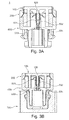
- Fig. 3A shows the electrical connector system 1 in a cut view, wherein the electrical plug connector 1 is in an uncoupled condition.
- the two housing parts 200, 400 of the plug connector 1 are engaged with each other.
- a connector position assurance member (CPA) member 120 is installed within the housing 200, 400.
- a separator means 120 of the CPA member 100 is arranged between the contact blades 533, 534.
- the cutting edges of the contact blades 533, 534 are in contact with each other in the shown uncoupled condition of the plug connector 1.
- the contact blades 533, 534 comprise a bendable portion 531, 532, which bendable portion is bent outwardly if the CPA member 100 is inserted fully into the housing 200, 400 of the plug connector 1. Thereby, the contact between the cutting edges is opened by the separator means 120.
- FIG. 3B This coupled condition can be seen in Fig. 3B .
- the CPA member 100 is fully inserted into the housing 200, 400 and the plug connector 1 is correctly coupled to a corresponding counter connector 700.
- the separator means 120 of the CPA member 100 By contacting and bending the contact blades 533, 534 by the separator means 120 of the CPA member 100, the electrical contact between the cutting edges of the contact blades 533, 534 is opened. Since the CPA member 100 is only insertable if the plug connector 1 is correctly coupled to the corresponding counter connector 700, the shorting clip 530 and in particular the contact between the cutting edges can be used for electrical or electronical monitoring the coupling condition.
Abstract
Description
- The invention relates to an electrical plug connector for a safety restraint system, preferably for an airbag ignition system and in particular to plug connectors comprising at least two terminals, with which it is possible to electrically or electronically monitor the correct coupling of the plug connector with a suitable counter connector.
- Passenger cars have nowadays a number of safety restraint systems, such as seat belts pretensions or airbags, as e.g. front and side airbags, which serve to cushion or limit the impact of a passenger with for example interior parts of passenger cars in case of an accident. Deceleration sensors in the passenger vehicle detect high deceleration values as they occur in case of an accident and send a trigger signal via wire or cable to the safety restraints system. An explosive device, known as squib, inflates the airbag or tightens the belt. The wires or cables of the deceleration sensor are connected to an electronic controlled unit and then to a squib, by means of a so called squib connector.
- To this day, the squib is usually provided with a socket or receptacle which contains two contact pins. The squib connector comprises a plug part or a plug connector corresponding to the socket, which plug part has two receptacles for the reception of the contact pins of the squib socket. To improve the connection between the squib and the plug connector, retainer inserts were developed, which are adapted to fit into the receptacle of standardized squibs and which facilitate and secure the connection between the squib and the plug connector. Alternatively to the use of retainers, connector position assurance members, better known as CPA members, were developed, that are mated with the plug connector after the plug connector is coupled to a corresponding counter connector. Such a CPA member is designed, so that a mating to the plug connector is only possible, if the plug connector is correctly coupled to the corresponding counter connector, i.e. the CPA member cannot be mated to the plug connector, if the plug connector is in an uncoupled or incorrectly coupled condition.
- The principle structure of an (airbag) squib is for example described in document
WO 2004/020 933 . The squib described in this document comprises an outer can enclosing a suitable pyrotechnic charge and an ignitor which is provided with two contact pins being electrically connected to an ignitor wire which can activate the charge of the squib. The ignitor further encloses a retainer for securing the squib to the housing of e.g. an airbag inflator, which retainer further comprises a plastic insert, which is injection molded around the pins of the squib and which serves to provide for mechanical fastening with the corresponding (squib) plug connector. The retainer is further provided with a so called shorting clip, which is usually an electro conductive metallic spring part, which in the non-coupled condition electrically connects the two pins of the squib with each other, i.e. shorting the same. - The shorting of the contact pins serves to prevent an unintended explosion of the pyrotechnic charge due to electrical potential differences occurring between the two contact pins, for example during transport or handling. The shorting circuit established by the shorting clip is separated and opens upon correct coupling of the corresponding plug connector into or with the retainer, respectively the corresponding counter connector. Alternatively, the shorting clip can be opened by a CPA member. Usually a contact pin member of a shorting clip is displaced by a plug part of the plug connector so that the two contact pins are no longer electrically connected. These shorting clips of the prior art are not only intended to prevent an unintentional ignition of the charge of the squib, but they also serve as a control or monitoring means of the correct coupling of the (squib) plug connector with its counterpart, i.e. the squib receptacle respectively the retainer or insert mounted therein. Upon correct coupling of the plug connector with its counterpart, the short circuit between the contact pins of the squib is automatically opened as described above, and this can be detected by means of suitable electrical/electronic monitoring means, as it is well known to the skilled person.
- In the latest developments, modern squibs are so reliable that a shorting clip is no longer absolutely necessary. Thanks to these improvements, an unintended ignition of the charge due to an electrical potential difference between the contact pins can be ruled out. Thus, for this new type of squib, the shorting clips could be disposed of, thereby reducing the manufacturing costs for the squib connectors considerably. However, the shorting clip is not only a safety feature for an unintended ignition of explosive charge of the airbag or belt pretension system but it is also commonly used to monitor the correct coupling of the plug connector with its counterpart.
- Document
WO 2010/143 078 discloses a squib connector that allows the electrical monitoring of the correct coupling of the plug connector. Therefore, the terminals of the connector are in electrical contact with each other in the uncoupled or incorrectly coupled condition of the plug connector. This electrical contact between the terminals is adapted for being separated upon correct coupling to a corresponding counter connector either automatically, i.e. by a retainer or by an actuating action, such as a mating a CPA member. Thus, disconnecting of the terminals can be monitored by a suitable monitoring means. The electrical contact between the terminals is established by contact means, which are provided with one bendable contact tongue. This bendable tongue is bent out of contact upon correct coupling of the plug connector by e.g. separator means. - The separator means is an electrical insulator and preferably comprises plastic. The contact surfaces of the shorting clip provided in the plug connector are typically in contact with the separator means. Due to the contact, of plastic and metallic surface of the shorting clip, the contact surface of the shorting clip can be contaminated with wear debris of the separator means. In particular due to relatively high operation temperatures typically up to 130°C, the contact surfaces of the shorting clip can be unintentionally coated with residual layers of plastic. This effect is known as fogging. In case of disassembling of the electrical plug connector and anew coupling to a corresponding counter connector, the monitoring function can be distorted, due to the residual layers, disposed on the contact surfaces of the shorting clip. Further residual layers may derive from the oxidation of the surfaces during the lifespan of the shorting clip. Thus, to avoid the building of residual layers, the contact surfaces are typically coated with e.g. a gold coating. Thus, high production costs arise.
- It is therefore an object of the present invention to provide a connector for a safety restraint system, which allows the electrical or electronic monitoring of the correct coupling of a (squib) plug connector with its corresponding counterpart, like for example a squib receptacle or a retainer insert for a squib receptacle. It is a further object of the invention to provide a connector with such a monitoring function, which is cheaper to produce than the known connectors. Further, it is a direct object of the invention to improve the electrical conductivity of the contacts of a shorting clip in order to make the monitoring function more reliable. These and other objects which become apparent upon reading the following description, are solved by connectors according to
claim 1 and a method to assemble an electrical connector assembly according to claim 13 and further according to electrical connector systems according to claim 16. - According to the invention, an electrical plug connector for a safety restraint system, preferably for an airbag ignition system is provided comprising: at least two contact terminals assigned to the plug connector and a shorting clip that is adapted to short circuit the at least two contact terminals in an uncoupled or incorrectly coupled condition of the plug connector, wherein the shorting clip comprises at least two contact blades, wherein each contact blade is electrically connected with a respective one of the at least two contact terminals, and wherein each of the contact blades comprises at least one cutting edge, which cutting edges contact each other, such that one edge cuts the other, when the plug connector is in an uncoupled or incorrectly coupled condition.
- The shorting clip allows, since it has at least two conditions i.e. a short circuit condition and an open/separated condition, to electrically or electronically monitor the coupling of the plug connector to a corresponding counter connector. It should be noted that the term "electrical or electronic monitoring" as used herein, is intended to describe all kinds of monitoring action which may make use of electrical signals. Further, it should be noted that the term "terminals" as used herein describes all parts associated with the terminals, which are arranged inside or close to the housing of the plug connector. In other words, also parts of the electrical signal lines are considered as being members of the terminals, as long as they are arranged inside or close to the plug connector housing.
- The contact blades, which are electrically connected with a respective one of the at least two contact terminals, allow the short circuiting of the terminals. A contact blade and a respective one of the at least two contact terminals can be integrally formed as one part or can be formed as a separate parts. In the second case, i.e. in the case of separate parts, the contact blade and the contact terminal have to be electrically connected for example by welding, soldering or by a wired line.
- The cutting edges of the contact blades are preferably sharp edges. At least one of the cutting edges, preferably both, comprise an included angle of less than 90°, more preferable an included angle of less than 70° and even more preferable an included angle of less than 60°. As it is known from knife geometry, the edge angle of a blade is the angle between the blade center and the blade side surface, whereas the included angle is the angle between both blade sides, i.e. formed by the two adjacent surfaces of the blade that form the edge. It has to be noted, that the cutting edge can alternatively be provided with a radius or a phase. These cutting edges allow a relatively small contact area, compared to conventional shorting clips having e.g. contact tongues, since the cutting edges are arranged such that one edge cuts the other. The term "cutting" has to be understood as abutting the edges across each other, wherein preferably a microscopic cut or notch is driven into at least one of the cutting edges. This cutting improves the electrical contact between the contact blades, since the electrical resistance of the contact can be reduced, e.g. by cutting through residual layers of plastic, oxides or the like. Further, the relatively small contact area leads to an increase in contact pressure under constant contact force. A contact force is e.g. applied due to the preload of the contact blades that are preferably formed as preloaded springs.
- Preferably, at least one of the two contact blades comprises a bendable portion, which bendable portion is bent to separate the contact between the cutting edges of the blades upon correct coupling of the plug connector. In particular, one bendable portion is sufficient to opened the contact between the cutting edges in order to monitor the correct coupling of the plug connector. The correct coupling of the plug connector occurs, if the plug connector is coupled mechanically correct to the corresponding counter connector. This mechanically correct coupling is achieved by the design of the plug connector and the corresponding counter connector. I.e. the bendable portion is bent to separate the contact between the cutting edges only if the coupling of the plug connector to the corresponding counter connector is correctly completed.
- The separation of the contact between the cutting edges can be achieved automatically or manually. An automatic separation is preferably achieved by a part of the counter connector, which disconnects (separates) the contact upon full insertion of the plug connector. Alternatively, it is also possible that a manual or automated actuating action is necessary to disconnect (separate) the contact. This is preferably achieved by the insertion of a connector positioning assurance (CPA) member, which can only be fully inserted into the plug connector upon correct coupling of the plug connector to the corresponding counter connector. Then, the CPA member mechanically disconnects (separates) the electrical contact between the terminals.
- Thus, preferably, the electrical plug further comprises a connector position assurance CPA member, which is insertable into a housing of the plug connector and which upon full insertion into the housing of plug connector separates the contact between the at least two cutting edges of the contact blades. Providing a CPA member, that is insertable into a housing, only if the plug connector and the corresponding counter connector are coupled correctly to each other and that separates the contact between the at least two cutting edges, allows an electrical or electronic monitoring of the plugging.
- Alternatively and preferably, the contact between the at least two cutting edges of the contact blades is adapted to be separated upon correct coupling to a corresponding counter connector of the plug connector, due to a mechanical contact with a separator means of the counter connector. This allows an automated separation of the contact between the cutting edges. Therefore, the plugging of the plug connector is facilitated, and no additional parts, such as a CPA member, are necessary. Preferably, the cutting edges of the at least two contact blades do not contact any structure of the plug connector, if the plug connector is correctly coupled to a corresponding counter connector. Being out of contact with any structure of plug connector, the contact blades are less prone to fogging. Fogging means the unintended deposition of material, such as plastic material from a member that is in contact with the contact blades. This member can for example be a separator means that is e.g. part of the CPA member or a corresponding retainer, and that is used to separate the contact between the cutting edges. The non-contact condition can for example be achieved, by providing the separator means with corresponding recesses or by designing the separator means, such that the separator means separates the contact by contacting an area that is different from the cutting edge of the contact blades.
- Preferably, the cutting edges of the at least two contact blades are punched edges, having preferably at least one punching burr. Punched edges, having preferably a punching burr provide sharp edges that allow very small contact areas. Thus the contact pressure can be significantly increased under constant contact force. Further, the cutting can be improved, so that the electrical resistance of the contact can be reduced. Further, by applying high contact pressures, the electrical contact is less prone to being separated by vibrations or the like. Preferably, the contact area of the contact between the at least two edges is smaller than 1 mm2, preferably smaller than 0.5 mm2 and most preferably smaller than 0.1 mm2. These contact areas have shown two provide an increased contact condition between the cutting edges.
- Preferably, at least one terminal and the respective contact blade are integrally formed as one part and even more preferably each contact blade is integrally formed with a respective one of the at least two contact terminals, wherein the integrally formed part preferably comprises a copper alloy. By integrally forming the terminal and the respective contact blade, manufacturing costs can be reduced and the number of parts to be handled during the assembly of the connector can be reduced. Thus, costs can be effectively minimized. Further, a copper alloy provides good electrical properties and a rigidity that allows the cutting of the cutting edges.
- Preferably, the contact blades are not gold plated. Due to the geometry of the cutting edges, a plating, such as gold plating is no longer necessary, since the cutting edges are less prone to residual layers, as described above, and the contact pressure between the cutting plates is significantly increased.
- Preferably, the cutting edges of the at least two contact blades are adapted to execute a relative cutting movement to each other, during establishing the electrical contact between the cutting edges. This cutting movement results in that one cutting edge scratches over the other cutting edge, so that possible contaminants or residual layers can be removed. Thus, the electrical contact and in particular the electrical conductivity of the contact can be increased and the electrical resistance of the contact can be reduced. Preferably, the cutting edges of the at least two contact blades are adapted to at least partly remove residual layers deposited on the cutting edges, in order to improve the electrical contact.
- The residual layers to be removed may comprise oxide layers, deposited contaminants and/or fogged plastic. Oxidation typically occurs during the use of the plug connector. Particularly in vehicles, high operating temperatures can occur. Thus, non-protected surfaces of the terminals or contact blades are prone to oxidation. Other contaminants may arise from corrosion or dust being present in the working environment. By at least partly removing these residual layers, the contact area can be at least partly cleaned, wherein the electrical conductivity of the contact is increased.
- The object is further solved by a method for assembling an electrical connector assembly, comprising the steps of providing a plug connector as described above, providing a corresponding counter connector and mating the plug connector with the corresponding counter connector, wherein the contact between the at least two cutting edges of the contact blades of the plug connector is separated upon correct coupling of the plug connector to the corresponding counter connector. The separation of the contact between the at least two cutting edges, allows the electrical or electronical monitoring of the plug condition. If the connector is mated correctly, the terminals are no longer short circuited, so that on the one hand the monitoring is possible and on the second hand, the safety restraint system is unlocked, since the pins of the restraint system, as described before, are no longer shorted via the terminals and the shorting clips.
- Preferably, the method further comprises the steps of providing a connector position assurance (CPA) member and inserting the connector position assurance member into a housing of the plug connector in order to separate the contact between the at least two cutting edges of the contact blades, upon full insertion of the connector position assurance member into the housing of the plug connector. Providing a connector position assurance member allows the manual separation of the contact between the at least two cutting edges. The CPA member therefore is inserted into the housing after the plug connector is plugged to the corresponding counter connector. This can preferably be achieved in one plugging movement. However, the insertion of the CPA member is preferably only possible, if the plug connector is mated correctly. Thereby, the separator means separates the contact between the cutting edges.
- Preferably, the method further comprises separating the contact between the at least two cutting edges of the contact blades upon correct coupling of the plug connector to a corresponding counter connector due to a mechanical contact with a separator means of the counter connector. If the separator means is provided within the counter connector, such as a retainer, the separation of the contact between the cutting edges can be achieved automatically. Thus no further manual insertion of an additional member, such as a CPA member, is necessary.
- The object is further solved by an electrical connector system comprising a plug connector and a corresponding counter connector, wherein the plug connector comprises a shorting clip as described above. This electrical connector system allows the monitoring of the correct coupled condition of the corresponding counter connector and the plug connector and further the short circuiting of the terminals of the plug connector.
- In the following, the invention is described exemplarily with reference to the enclosed figures, in which
- Fig. 1
- shows a schematic illustration of a plug connector in an exploded view;
- Figs. 2A -D
- show a schematic illustration of a terminal assembly, comprising a shorting clip, and
- Figs. 3A - 3B
- show a schematic cut view of an electrical plug connector comprising a CPA member in an uncoupled and a correctly coupled condition.
- In particular,
Fig. 1 shows an exploded view of anelectrical plug connector 1 for a safety restraint system, preferably for an airbag ignition system. Theelectrical plug connector 1 comprises a housing, wherein the housing comprises at least two parts, amain part 400 and acover 200. Thehousing terminal assembly 500, comprising at least 2terminals terminals terminal assembly 500 further comprises ashorting clip 530. The shortingclip 530 is adapted to short circuit the at least twocontact terminals soldering member corresponding signal line electrical plug connector 1 comprises a connector position assurance (CPA)member 100 which is insertable into thehousing plug connector 1. TheCPA member 100 will upon full insertion into thehousing plug connector 1 separate the contact between the at least two cutting edges (not shown inFig. 1 ) of the shortingclip 530. -
Figs. 2A to 2D show theterminal assembly 500 in greater detail. TherebyFig. 2A shows theterminal assembly 500 comprising twoterminals terminals respective contact blade contact blades bendable portion bendable portion edges Fig. 2C . Still further, each terminal is assigned with a respective welding orsoldering member corresponding contact blade -
Fig. 2B shows theterminal assembly 500 ofFig. 2A from a different view. In particular, the terminal assembly is shown with view on thecontact blades Fig. 2C shows a detailed enlarged view of thecontact blades Fig. 2B . As can be best seen inFig. 2C , eachcontact blade cutting edge edges contact area 537. The cutting edges are preferably sharp edges and most preferably punching edges, having a punching burr. Thus, thecontact area 537 can be significantly reduced and the contact pressure is increased under constant contact force. Further, due to the cutting of the cutting edges with one another, residual layers such as oxide layers, fogged plastic layers or contaminant layers or the like can be cut.Fig. 2D shows theterminal assembly 500 in a side view. In particular, thecontact blades clip 530 are shown. As can be seen, the cuttingedges cutting blades -
Fig. 3A shows theelectrical connector system 1 in a cut view, wherein theelectrical plug connector 1 is in an uncoupled condition. The twohousing parts plug connector 1, are engaged with each other. A connector position assurance member (CPA)member 120 is installed within thehousing CPA member 100 is arranged between thecontact blades contact blades plug connector 1. Thecontact blades bendable portion CPA member 100 is inserted fully into thehousing plug connector 1. Thereby, the contact between the cutting edges is opened by the separator means 120. - This coupled condition can be seen in
Fig. 3B . As shown inFig. 3B , theCPA member 100 is fully inserted into thehousing plug connector 1 is correctly coupled to acorresponding counter connector 700. By contacting and bending thecontact blades CPA member 100, the electrical contact between the cutting edges of thecontact blades CPA member 100 is only insertable if theplug connector 1 is correctly coupled to thecorresponding counter connector 700, the shortingclip 530 and in particular the contact between the cutting edges can be used for electrical or electronical monitoring the coupling condition. -
- 1
- Electrical plug connector
- 100
- CPA member
- 120
- Separator means
- 200
- Housing, cover
- 400
- Housing, main part
- 500
- Terminal assembly
- 521, 522
- Terminals
- 530
- Shorting clip
- 511, 512
- Welding or soldering element
- 531, 532
- Bendable portion
- 533, 534
- Contact blades
- 535, 536
- Cutting edges
- 537
- Contact area
- α
- Angle between cutting edges
- 700
- Corresponding counter connector
Claims (16)
- Electrical plug connector (1) for a safety restraint system, preferably for an airbag ignition system, comprising:at least two contact terminals (521, 522) assigned to the plug connector (1); anda shorting clip (530), that is adapted to short-circuit the at least two contact terminals (521, 522) in an uncoupled or incorrectly coupled condition of the plug connector (1), wherein the shorting clip (530) comprisesat least two contact blades (533, 534), wherein each contact blade (533; 534) is electrically connected with a respective one of the at least two contact terminals (521; 522), and wherein each of the contact blades (533, 534) comprises at least one cutting edge (535, 536), which cutting edges (535, 536) contact each other, such that one edge cuts the other, when the plug connector (1) is in in an uncoupled or incorrectly coupled condition.
- Electrical plug connector (1) according to claim 1, wherein at least one of the two contact blades (533, 534) comprises a bendable portion (531, 532), which bendable portion (531, 532) is bend to separate the contact between the cutting edges (535, 536) of the contact blades (533, 534) upon correct coupling of the plug-connector (1).
- Electrical plug connector (1) according to any one of claims 1 or 2, further comprising a connector position assurance (CPA) member (100), which is insertable into a housing (200, 400) of the plug connector (1) and which upon full insertion into the housing (200, 400) of the plug connector (1) separates the contact between the at least two cutting edges (535, 536) of the contact blades (533, 534).
- Electrical plug connector (1) according to any one of claims 1 or 2, wherein the contact between the at least two cutting edges (535, 536) of the contact blades (533, 534) is adapted to be separated upon correct coupling to a corresponding counter-connector (700) of the plug-connector (1), due to a mechanical contact with a separator means of the counter-connector (700).
- Electrical plug connector (1) according to any preceding claim, wherein the cutting edges (535, 536) of the at least two contact blades (533, 534) do not contact any structure of the plug connector (1), if the plug connector (1) is correctly coupled to a corresponding counter connector (710).
- Electrical plug connector (1) according to any preceding claim, wherein the cutting edges (535, 536) of the at least two contact blades (533, 534) are punched edges, having preferably at least one punching burr.
- Electrical plug connector (1) according to any preceding claim, wherein the contact area (537) of the contact between the at least two cutting edges (535, 536) is smaller than 1 mm2, preferably smaller than 0.5 mm2 and most preferably smaller than 0.1 mm2.
- Electrical plug connector (1) according to any preceding claim, wherein at least one terminal (521, 522) and at least one contact blade (533, 534) are integrally formed as one part and wherein preferably each contact blade (533; 534) is integrally formed with a respective one of the at least two contact terminals (521; 522) and further preferably comprises a copper alloy.
- Electrical plug connector (1) according to any preceding claim, wherein the contact blades (533, 534) are not gold plated.
- Electrical plug connector (1) according to any preceding claim, wherein the cutting edges (535, 536) of the at least two contact blades (533, 534) are adapted to execute a relative cutting movement to each other, during establishing the electrical contact between the cutting edges (535, 536).
- Electrical plug connector (1) according to any preceding claim, wherein the cutting edges (535, 536) of the at least two contact blades (533, 534) are adapted to at least partly remove residual layers deposited on the cutting edges (535, 536), in order to improve an electrical contact, wherein the residual layers to be removed may comprise oxide layers, deposited contaminants and/or fogged plastic.
- Electrical plug connector (1) according to any preceding claim, wherein at least one of the cutting edges, preferably both, comprise an included angle of less than 90°, more preferable an included angle of less than 70° and even more preferable an included angle of less than 60°.
- Method for assembling an electrical connector assembly comprising the steps of:Providing a plug connector (1) according to any one of claims 1 to 12;Providing a corresponding counter connector (710); andMating the plug connector (1) with the corresponding counter connector (710), wherein the contact between the at least two the cutting edges (535, 536) of the contact blades (533, 534) of the plug connector (1) is separated upon correct coupling the plug connector (1) to the corresponding counter-connector (710).
- The method according to claim 13, comprising further the steps of:Providing a connector position assurance (CPA) member (100), andInserting the connector position assurance member (100) into a housing (200, 400) of the plug connector (1) in order to separate the contact between the at least two cutting edges (535, 536) of the contact blades (533, 534), upon full insertion of the connector position assurance member (100) into the housing (200, 400) of the plug connector (1).
- The method according to claim 13, comprising further the steps of:Separating the contact between the at least two cutting edges (535, 536) of the contact blades (533, 534) upon correct coupling the plug connector (1) to a corresponding counter-connector (700), due to a mechanical contact with a separator means of the counter-connector (700).
- Electrical connector system comprising a plug connector (1) and a corresponding counter-connector (700), wherein the plug connector (1) comprises a shorting clip (530) according to any one of claims 1 to 12.
Priority Applications (3)
| Application Number | Priority Date | Filing Date | Title |
|---|---|---|---|
| EP15176757.1A EP3118943B1 (en) | 2015-07-15 | 2015-07-15 | Electrical plug connector for a safety restraint system and connection method thereof. |
| US15/208,822 US9780502B2 (en) | 2015-07-15 | 2016-07-13 | Electrical plug connector for a safety restraint system |
| CN201610656370.XA CN106654765B (en) | 2015-07-15 | 2016-07-14 | Electrical plug connector for safety restraint system |
Applications Claiming Priority (1)
| Application Number | Priority Date | Filing Date | Title |
|---|---|---|---|
| EP15176757.1A EP3118943B1 (en) | 2015-07-15 | 2015-07-15 | Electrical plug connector for a safety restraint system and connection method thereof. |
Publications (2)
| Publication Number | Publication Date |
|---|---|
| EP3118943A1 true EP3118943A1 (en) | 2017-01-18 |
| EP3118943B1 EP3118943B1 (en) | 2019-06-12 |
Family
ID=53546164
Family Applications (1)
| Application Number | Title | Priority Date | Filing Date |
|---|---|---|---|
| EP15176757.1A Active EP3118943B1 (en) | 2015-07-15 | 2015-07-15 | Electrical plug connector for a safety restraint system and connection method thereof. |
Country Status (3)
| Country | Link |
|---|---|
| US (1) | US9780502B2 (en) |
| EP (1) | EP3118943B1 (en) |
| CN (1) | CN106654765B (en) |
Cited By (2)
| Publication number | Priority date | Publication date | Assignee | Title |
|---|---|---|---|---|
| WO2018197682A1 (en) * | 2017-04-28 | 2018-11-01 | Amphenol-Tuchel Electronics Gmbh | Contact element arrangement |
| US11843200B2 (en) | 2020-08-25 | 2023-12-12 | Te Connectivity Germany Gmbh | Connector with a position assurance element having a contact receptacle |
Families Citing this family (2)
| Publication number | Priority date | Publication date | Assignee | Title |
|---|---|---|---|---|
| FR3059478A1 (en) * | 2016-11-30 | 2018-06-01 | Tyco Electronics France Sas | ELECTRICAL CONNECTOR FOR A SECURITY RETENTION SYSTEM |
| CN112310691B (en) * | 2020-09-24 | 2023-11-10 | 宁德时代新能源科技股份有限公司 | Position assurance device, connector assembly, battery and power utilization device |
Citations (6)
| Publication number | Priority date | Publication date | Assignee | Title |
|---|---|---|---|---|
| US5277607A (en) * | 1993-01-15 | 1994-01-11 | The Whitaker Corporation | Electrical connector with shorting contacts which wipe against each other |
| EP1115181A1 (en) * | 2000-01-07 | 2001-07-11 | Sumitomo Wiring Systems, Ltd. | Electrical connector |
| WO2004020933A1 (en) | 2002-08-30 | 2004-03-11 | Special Devices, Inc. | Initiator having integral features for orienting and holding an insertable electrical shunt |
| US6764345B1 (en) * | 2003-05-27 | 2004-07-20 | Tyco Electronics Corporation | Electrical card edge connector with dual shorting contacts |
| WO2010143078A2 (en) | 2009-06-09 | 2010-12-16 | Fci | Connector for a safety restraint system |
| DE102009053052A1 (en) * | 2009-11-16 | 2011-05-19 | Tyco Electronics Amp Gmbh | Electrical connector element for an airbag connection |
Family Cites Families (2)
| Publication number | Priority date | Publication date | Assignee | Title |
|---|---|---|---|---|
| JP5638026B2 (en) * | 2012-05-01 | 2014-12-10 | ヒロセ電機株式会社 | Electrical connector assembly |
| CN103579854B (en) * | 2012-08-10 | 2016-03-23 | 菲尼克斯电气有限两合公司 | Electric plug connectors |
-
2015
- 2015-07-15 EP EP15176757.1A patent/EP3118943B1/en active Active
-
2016
- 2016-07-13 US US15/208,822 patent/US9780502B2/en active Active
- 2016-07-14 CN CN201610656370.XA patent/CN106654765B/en active Active
Patent Citations (6)
| Publication number | Priority date | Publication date | Assignee | Title |
|---|---|---|---|---|
| US5277607A (en) * | 1993-01-15 | 1994-01-11 | The Whitaker Corporation | Electrical connector with shorting contacts which wipe against each other |
| EP1115181A1 (en) * | 2000-01-07 | 2001-07-11 | Sumitomo Wiring Systems, Ltd. | Electrical connector |
| WO2004020933A1 (en) | 2002-08-30 | 2004-03-11 | Special Devices, Inc. | Initiator having integral features for orienting and holding an insertable electrical shunt |
| US6764345B1 (en) * | 2003-05-27 | 2004-07-20 | Tyco Electronics Corporation | Electrical card edge connector with dual shorting contacts |
| WO2010143078A2 (en) | 2009-06-09 | 2010-12-16 | Fci | Connector for a safety restraint system |
| DE102009053052A1 (en) * | 2009-11-16 | 2011-05-19 | Tyco Electronics Amp Gmbh | Electrical connector element for an airbag connection |
Cited By (7)
| Publication number | Priority date | Publication date | Assignee | Title |
|---|---|---|---|---|
| WO2018197682A1 (en) * | 2017-04-28 | 2018-11-01 | Amphenol-Tuchel Electronics Gmbh | Contact element arrangement |
| CN110720162A (en) * | 2017-04-28 | 2020-01-21 | 安费诺-图赫尔电子有限公司 | Contact element arrangement |
| US20200099155A1 (en) * | 2017-04-28 | 2020-03-26 | Amphenol-Tuchel Electronics Gmbh | Contact element arrangement |
| JP2020518113A (en) * | 2017-04-28 | 2020-06-18 | アンフェノル−テュッヘル・エレクトロニクス・ゲーエムベーハー | Contact element device |
| US10950965B2 (en) | 2017-04-28 | 2021-03-16 | Amphenol-Tuchel Electronics Gmbh | Contact element arrangement |
| DE102017109246B4 (en) | 2017-04-28 | 2024-02-15 | Amphenol-Tuchel Electronics Gmbh | Contact element arrangement |
| US11843200B2 (en) | 2020-08-25 | 2023-12-12 | Te Connectivity Germany Gmbh | Connector with a position assurance element having a contact receptacle |
Also Published As
| Publication number | Publication date |
|---|---|
| EP3118943B1 (en) | 2019-06-12 |
| CN106654765A (en) | 2017-05-10 |
| US20170018889A1 (en) | 2017-01-19 |
| US9780502B2 (en) | 2017-10-03 |
| CN106654765B (en) | 2020-06-26 |
Similar Documents
| Publication | Publication Date | Title |
|---|---|---|
| EP3116075B1 (en) | Electrical plug connector for a safety restraint system | |
| EP2440433B1 (en) | Connector for a safety restraint system | |
| US9780502B2 (en) | Electrical plug connector for a safety restraint system | |
| US6893277B2 (en) | Squib connector assembly with CPA | |
| CN102239601B (en) | Connection assembly on circuit boards | |
| US9356394B2 (en) | Self-rejecting connector | |
| US5314345A (en) | Electrical connection system with interlock | |
| EP2822107A1 (en) | Electrical connector and squib connection device | |
| WO2005069445A1 (en) | Electrical connector with spring back/self rejection feature | |
| US9537267B2 (en) | Connector for a safety restraint system | |
| CN108123328B (en) | Electrical connector for safety restraint system | |
| EP3474386B1 (en) | An electrical connector comprising a flat electrical contact terminal | |
| CN112038815B (en) | Connector with a locking member | |
| US9831611B2 (en) | Electrical plug connector | |
| US10938138B2 (en) | Electrical contact terminal for an electrical plug connector for a safety restraint system | |
| US10665994B2 (en) | Multiple-contact plug with an integrated short-circuit link element | |
| EP3240117A1 (en) | An electrical connector with terminal centering system | |
| EP4145645A1 (en) | Electrical connector and methods |
Legal Events
| Date | Code | Title | Description |
|---|---|---|---|
| PUAI | Public reference made under article 153(3) epc to a published international application that has entered the european phase |
Free format text: ORIGINAL CODE: 0009012 |
|
| STAA | Information on the status of an ep patent application or granted ep patent |
Free format text: STATUS: THE APPLICATION HAS BEEN PUBLISHED |
|
| AK | Designated contracting states |
Kind code of ref document: A1 Designated state(s): AL AT BE BG CH CY CZ DE DK EE ES FI FR GB GR HR HU IE IS IT LI LT LU LV MC MK MT NL NO PL PT RO RS SE SI SK SM TR |
|
| AX | Request for extension of the european patent |
Extension state: BA ME |
|
| STAA | Information on the status of an ep patent application or granted ep patent |
Free format text: STATUS: REQUEST FOR EXAMINATION WAS MADE |
|
| 17P | Request for examination filed |
Effective date: 20170718 |
|
| RBV | Designated contracting states (corrected) |
Designated state(s): AL AT BE BG CH CY CZ DE DK EE ES FI FR GB GR HR HU IE IS IT LI LT LU LV MC MK MT NL NO PL PT RO RS SE SI SK SM TR |
|
| RAP1 | Party data changed (applicant data changed or rights of an application transferred) |
Owner name: APTIV TECHNOLOGIES LIMITED |
|
| GRAP | Despatch of communication of intention to grant a patent |
Free format text: ORIGINAL CODE: EPIDOSNIGR1 |
|
| STAA | Information on the status of an ep patent application or granted ep patent |
Free format text: STATUS: GRANT OF PATENT IS INTENDED |
|
| RIC1 | Information provided on ipc code assigned before grant |
Ipc: H01R 13/641 20060101ALI20190131BHEP Ipc: H01R 13/642 20060101ALI20190131BHEP Ipc: H01R 13/703 20060101AFI20190131BHEP Ipc: H01R 13/71 20060101ALI20190131BHEP |
|
| INTG | Intention to grant announced |
Effective date: 20190218 |
|
| GRAS | Grant fee paid |
Free format text: ORIGINAL CODE: EPIDOSNIGR3 |
|
| GRAA | (expected) grant |
Free format text: ORIGINAL CODE: 0009210 |
|
| STAA | Information on the status of an ep patent application or granted ep patent |
Free format text: STATUS: THE PATENT HAS BEEN GRANTED |
|
| AK | Designated contracting states |
Kind code of ref document: B1 Designated state(s): AL AT BE BG CH CY CZ DE DK EE ES FI FR GB GR HR HU IE IS IT LI LT LU LV MC MK MT NL NO PL PT RO RS SE SI SK SM TR |
|
| REG | Reference to a national code |
Ref country code: GB Ref legal event code: FG4D |
|
| REG | Reference to a national code |
Ref country code: CH Ref legal event code: EP |
|
| REG | Reference to a national code |
Ref country code: AT Ref legal event code: REF Ref document number: 1143836 Country of ref document: AT Kind code of ref document: T Effective date: 20190615 |
|
| REG | Reference to a national code |
Ref country code: DE Ref legal event code: R096 Ref document number: 602015031670 Country of ref document: DE |
|
| REG | Reference to a national code |
Ref country code: IE Ref legal event code: FG4D |
|
| REG | Reference to a national code |
Ref country code: NL Ref legal event code: MP Effective date: 20190612 |
|
| REG | Reference to a national code |
Ref country code: LT Ref legal event code: MG4D |
|
| PG25 | Lapsed in a contracting state [announced via postgrant information from national office to epo] |
Ref country code: NO Free format text: LAPSE BECAUSE OF FAILURE TO SUBMIT A TRANSLATION OF THE DESCRIPTION OR TO PAY THE FEE WITHIN THE PRESCRIBED TIME-LIMIT Effective date: 20190912 Ref country code: FI Free format text: LAPSE BECAUSE OF FAILURE TO SUBMIT A TRANSLATION OF THE DESCRIPTION OR TO PAY THE FEE WITHIN THE PRESCRIBED TIME-LIMIT Effective date: 20190612 Ref country code: HR Free format text: LAPSE BECAUSE OF FAILURE TO SUBMIT A TRANSLATION OF THE DESCRIPTION OR TO PAY THE FEE WITHIN THE PRESCRIBED TIME-LIMIT Effective date: 20190612 Ref country code: LT Free format text: LAPSE BECAUSE OF FAILURE TO SUBMIT A TRANSLATION OF THE DESCRIPTION OR TO PAY THE FEE WITHIN THE PRESCRIBED TIME-LIMIT Effective date: 20190612 Ref country code: AL Free format text: LAPSE BECAUSE OF FAILURE TO SUBMIT A TRANSLATION OF THE DESCRIPTION OR TO PAY THE FEE WITHIN THE PRESCRIBED TIME-LIMIT Effective date: 20190612 Ref country code: SE Free format text: LAPSE BECAUSE OF FAILURE TO SUBMIT A TRANSLATION OF THE DESCRIPTION OR TO PAY THE FEE WITHIN THE PRESCRIBED TIME-LIMIT Effective date: 20190612 |
|
| PG25 | Lapsed in a contracting state [announced via postgrant information from national office to epo] |
Ref country code: GR Free format text: LAPSE BECAUSE OF FAILURE TO SUBMIT A TRANSLATION OF THE DESCRIPTION OR TO PAY THE FEE WITHIN THE PRESCRIBED TIME-LIMIT Effective date: 20190913 Ref country code: LV Free format text: LAPSE BECAUSE OF FAILURE TO SUBMIT A TRANSLATION OF THE DESCRIPTION OR TO PAY THE FEE WITHIN THE PRESCRIBED TIME-LIMIT Effective date: 20190612 Ref country code: RS Free format text: LAPSE BECAUSE OF FAILURE TO SUBMIT A TRANSLATION OF THE DESCRIPTION OR TO PAY THE FEE WITHIN THE PRESCRIBED TIME-LIMIT Effective date: 20190612 Ref country code: BG Free format text: LAPSE BECAUSE OF FAILURE TO SUBMIT A TRANSLATION OF THE DESCRIPTION OR TO PAY THE FEE WITHIN THE PRESCRIBED TIME-LIMIT Effective date: 20190912 |
|
| REG | Reference to a national code |
Ref country code: AT Ref legal event code: MK05 Ref document number: 1143836 Country of ref document: AT Kind code of ref document: T Effective date: 20190612 |
|
| PG25 | Lapsed in a contracting state [announced via postgrant information from national office to epo] |
Ref country code: SK Free format text: LAPSE BECAUSE OF FAILURE TO SUBMIT A TRANSLATION OF THE DESCRIPTION OR TO PAY THE FEE WITHIN THE PRESCRIBED TIME-LIMIT Effective date: 20190612 Ref country code: RO Free format text: LAPSE BECAUSE OF FAILURE TO SUBMIT A TRANSLATION OF THE DESCRIPTION OR TO PAY THE FEE WITHIN THE PRESCRIBED TIME-LIMIT Effective date: 20190612 Ref country code: CZ Free format text: LAPSE BECAUSE OF FAILURE TO SUBMIT A TRANSLATION OF THE DESCRIPTION OR TO PAY THE FEE WITHIN THE PRESCRIBED TIME-LIMIT Effective date: 20190612 Ref country code: PT Free format text: LAPSE BECAUSE OF FAILURE TO SUBMIT A TRANSLATION OF THE DESCRIPTION OR TO PAY THE FEE WITHIN THE PRESCRIBED TIME-LIMIT Effective date: 20191014 Ref country code: NL Free format text: LAPSE BECAUSE OF FAILURE TO SUBMIT A TRANSLATION OF THE DESCRIPTION OR TO PAY THE FEE WITHIN THE PRESCRIBED TIME-LIMIT Effective date: 20190612 Ref country code: EE Free format text: LAPSE BECAUSE OF FAILURE TO SUBMIT A TRANSLATION OF THE DESCRIPTION OR TO PAY THE FEE WITHIN THE PRESCRIBED TIME-LIMIT Effective date: 20190612 Ref country code: AT Free format text: LAPSE BECAUSE OF FAILURE TO SUBMIT A TRANSLATION OF THE DESCRIPTION OR TO PAY THE FEE WITHIN THE PRESCRIBED TIME-LIMIT Effective date: 20190612 |
|
| PG25 | Lapsed in a contracting state [announced via postgrant information from national office to epo] |
Ref country code: IT Free format text: LAPSE BECAUSE OF FAILURE TO SUBMIT A TRANSLATION OF THE DESCRIPTION OR TO PAY THE FEE WITHIN THE PRESCRIBED TIME-LIMIT Effective date: 20190612 Ref country code: SM Free format text: LAPSE BECAUSE OF FAILURE TO SUBMIT A TRANSLATION OF THE DESCRIPTION OR TO PAY THE FEE WITHIN THE PRESCRIBED TIME-LIMIT Effective date: 20190612 Ref country code: ES Free format text: LAPSE BECAUSE OF FAILURE TO SUBMIT A TRANSLATION OF THE DESCRIPTION OR TO PAY THE FEE WITHIN THE PRESCRIBED TIME-LIMIT Effective date: 20190612 Ref country code: IS Free format text: LAPSE BECAUSE OF FAILURE TO SUBMIT A TRANSLATION OF THE DESCRIPTION OR TO PAY THE FEE WITHIN THE PRESCRIBED TIME-LIMIT Effective date: 20191012 |
|
| REG | Reference to a national code |
Ref country code: CH Ref legal event code: PL |
|
| REG | Reference to a national code |
Ref country code: DE Ref legal event code: R097 Ref document number: 602015031670 Country of ref document: DE |
|
| PG25 | Lapsed in a contracting state [announced via postgrant information from national office to epo] |
Ref country code: MC Free format text: LAPSE BECAUSE OF FAILURE TO SUBMIT A TRANSLATION OF THE DESCRIPTION OR TO PAY THE FEE WITHIN THE PRESCRIBED TIME-LIMIT Effective date: 20190612 Ref country code: TR Free format text: LAPSE BECAUSE OF FAILURE TO SUBMIT A TRANSLATION OF THE DESCRIPTION OR TO PAY THE FEE WITHIN THE PRESCRIBED TIME-LIMIT Effective date: 20190612 |
|
| REG | Reference to a national code |
Ref country code: BE Ref legal event code: MM Effective date: 20190731 |
|
| PLBE | No opposition filed within time limit |
Free format text: ORIGINAL CODE: 0009261 |
|
| STAA | Information on the status of an ep patent application or granted ep patent |
Free format text: STATUS: NO OPPOSITION FILED WITHIN TIME LIMIT |
|
| PG25 | Lapsed in a contracting state [announced via postgrant information from national office to epo] |
Ref country code: PL Free format text: LAPSE BECAUSE OF FAILURE TO SUBMIT A TRANSLATION OF THE DESCRIPTION OR TO PAY THE FEE WITHIN THE PRESCRIBED TIME-LIMIT Effective date: 20190612 Ref country code: DK Free format text: LAPSE BECAUSE OF FAILURE TO SUBMIT A TRANSLATION OF THE DESCRIPTION OR TO PAY THE FEE WITHIN THE PRESCRIBED TIME-LIMIT Effective date: 20190612 |
|
| 26N | No opposition filed |
Effective date: 20200313 |
|
| PG25 | Lapsed in a contracting state [announced via postgrant information from national office to epo] |
Ref country code: LU Free format text: LAPSE BECAUSE OF NON-PAYMENT OF DUE FEES Effective date: 20190715 Ref country code: BE Free format text: LAPSE BECAUSE OF NON-PAYMENT OF DUE FEES Effective date: 20190731 Ref country code: CH Free format text: LAPSE BECAUSE OF NON-PAYMENT OF DUE FEES Effective date: 20190731 Ref country code: LI Free format text: LAPSE BECAUSE OF NON-PAYMENT OF DUE FEES Effective date: 20190731 Ref country code: SI Free format text: LAPSE BECAUSE OF FAILURE TO SUBMIT A TRANSLATION OF THE DESCRIPTION OR TO PAY THE FEE WITHIN THE PRESCRIBED TIME-LIMIT Effective date: 20190612 Ref country code: IS Free format text: LAPSE BECAUSE OF FAILURE TO SUBMIT A TRANSLATION OF THE DESCRIPTION OR TO PAY THE FEE WITHIN THE PRESCRIBED TIME-LIMIT Effective date: 20200224 |
|
| PG2D | Information on lapse in contracting state deleted |
Ref country code: IS |
|
| PG25 | Lapsed in a contracting state [announced via postgrant information from national office to epo] |
Ref country code: IE Free format text: LAPSE BECAUSE OF NON-PAYMENT OF DUE FEES Effective date: 20190715 |
|
| PG25 | Lapsed in a contracting state [announced via postgrant information from national office to epo] |
Ref country code: CY Free format text: LAPSE BECAUSE OF FAILURE TO SUBMIT A TRANSLATION OF THE DESCRIPTION OR TO PAY THE FEE WITHIN THE PRESCRIBED TIME-LIMIT Effective date: 20190612 |
|
| PG25 | Lapsed in a contracting state [announced via postgrant information from national office to epo] |
Ref country code: HU Free format text: LAPSE BECAUSE OF FAILURE TO SUBMIT A TRANSLATION OF THE DESCRIPTION OR TO PAY THE FEE WITHIN THE PRESCRIBED TIME-LIMIT; INVALID AB INITIO Effective date: 20150715 Ref country code: MT Free format text: LAPSE BECAUSE OF FAILURE TO SUBMIT A TRANSLATION OF THE DESCRIPTION OR TO PAY THE FEE WITHIN THE PRESCRIBED TIME-LIMIT Effective date: 20190612 |
|
| PG25 | Lapsed in a contracting state [announced via postgrant information from national office to epo] |
Ref country code: MK Free format text: LAPSE BECAUSE OF FAILURE TO SUBMIT A TRANSLATION OF THE DESCRIPTION OR TO PAY THE FEE WITHIN THE PRESCRIBED TIME-LIMIT Effective date: 20190612 |
|
| P01 | Opt-out of the competence of the unified patent court (upc) registered |
Effective date: 20230424 |
|
| PGFP | Annual fee paid to national office [announced via postgrant information from national office to epo] |
Ref country code: GB Payment date: 20230718 Year of fee payment: 9 |
|
| PGFP | Annual fee paid to national office [announced via postgrant information from national office to epo] |
Ref country code: FR Payment date: 20230724 Year of fee payment: 9 Ref country code: DE Payment date: 20230725 Year of fee payment: 9 |