EP3118928A1 - Input/output coupling structure of dielectric waveguide - Google Patents
Input/output coupling structure of dielectric waveguide Download PDFInfo
- Publication number
- EP3118928A1 EP3118928A1 EP16001577.2A EP16001577A EP3118928A1 EP 3118928 A1 EP3118928 A1 EP 3118928A1 EP 16001577 A EP16001577 A EP 16001577A EP 3118928 A1 EP3118928 A1 EP 3118928A1
- Authority
- EP
- European Patent Office
- Prior art keywords
- dielectric waveguide
- slot
- ground pattern
- side ground
- opening
- Prior art date
- Legal status (The legal status is an assumption and is not a legal conclusion. Google has not performed a legal analysis and makes no representation as to the accuracy of the status listed.)
- Withdrawn
Links
Images


Classifications
-
- H—ELECTRICITY
- H01—ELECTRIC ELEMENTS
- H01P—WAVEGUIDES; RESONATORS, LINES, OR OTHER DEVICES OF THE WAVEGUIDE TYPE
- H01P5/00—Coupling devices of the waveguide type
- H01P5/08—Coupling devices of the waveguide type for linking dissimilar lines or devices
- H01P5/087—Transitions to a dielectric waveguide
-
- H—ELECTRICITY
- H01—ELECTRIC ELEMENTS
- H01P—WAVEGUIDES; RESONATORS, LINES, OR OTHER DEVICES OF THE WAVEGUIDE TYPE
- H01P5/00—Coupling devices of the waveguide type
- H01P5/08—Coupling devices of the waveguide type for linking dissimilar lines or devices
- H01P5/10—Coupling devices of the waveguide type for linking dissimilar lines or devices for coupling balanced with unbalanced lines or devices
- H01P5/107—Hollow-waveguide/strip-line transitions
-
- H—ELECTRICITY
- H01—ELECTRIC ELEMENTS
- H01P—WAVEGUIDES; RESONATORS, LINES, OR OTHER DEVICES OF THE WAVEGUIDE TYPE
- H01P3/00—Waveguides; Transmission lines of the waveguide type
- H01P3/16—Dielectric waveguides, i.e. without a longitudinal conductor
-
- H—ELECTRICITY
- H05—ELECTRIC TECHNIQUES NOT OTHERWISE PROVIDED FOR
- H05K—PRINTED CIRCUITS; CASINGS OR CONSTRUCTIONAL DETAILS OF ELECTRIC APPARATUS; MANUFACTURE OF ASSEMBLAGES OF ELECTRICAL COMPONENTS
- H05K1/00—Printed circuits
- H05K1/02—Details
- H05K1/0213—Electrical arrangements not otherwise provided for
- H05K1/0237—High frequency adaptations
- H05K1/0242—Structural details of individual signal conductors, e.g. related to the skin effect
-
- H—ELECTRICITY
- H05—ELECTRIC TECHNIQUES NOT OTHERWISE PROVIDED FOR
- H05K—PRINTED CIRCUITS; CASINGS OR CONSTRUCTIONAL DETAILS OF ELECTRIC APPARATUS; MANUFACTURE OF ASSEMBLAGES OF ELECTRICAL COMPONENTS
- H05K1/00—Printed circuits
- H05K1/02—Details
- H05K1/11—Printed elements for providing electric connections to or between printed circuits
- H05K1/115—Via connections; Lands around holes or via connections
-
- H—ELECTRICITY
- H01—ELECTRIC ELEMENTS
- H01P—WAVEGUIDES; RESONATORS, LINES, OR OTHER DEVICES OF THE WAVEGUIDE TYPE
- H01P3/00—Waveguides; Transmission lines of the waveguide type
- H01P3/12—Hollow waveguides
- H01P3/122—Dielectric loaded (not air)
Abstract
Description
- This application is based on Japanese Patent Application No.
2015-142733 filed on July 17, 2015 - The present invention relates to an input/output coupling structure between a dielectric waveguide and a printed circuit board on which the dielectric waveguide is to be mounted, and, more particularly, to a bandwidth widening technique for the input/output coupling structure.
- In recent years, mobile communications devices have become widespread, and frequencies of GHz bands have come to be used for communications therebetween. Then, in a base station which relays the communication between the mobile communications devices, a dielectric waveguide filter has been used which comprises a combination of a plurality of waveguide resonators.
- The dielectric waveguide filter can be dramatically downsized due to a wavelength shortening effect of dielectric body as compared to a conventional cavity waveguide, and thereby can be utilized while being directly mounted on a printed circuit board.
- However, the dielectric waveguide, and a strip line used in the printed circuit board, are different from each other in terms of a transmission mode of electromagnetic wave. Thus, in the case of using the dielectric waveguide such as the dielectric waveguide filter while being directly mounted on the printed circuit board, it is necessary to provide an input/output coupling structure having a wideband characteristic for converting a mode from the strip line to the dielectric waveguide.
-
FIG. 5 is an exploded perspective view illustrating an example of a conventional dielectric waveguide input/output coupling structure described inJP 2000-049506A dielectric waveguide 1 mounted on a surface of a printedcircuit board 4. InFIG. 5 , a region exposing the dielectric body is slashed. - As illustrated in
FIG. 5 , thedielectric waveguide 1 comprises an approximately rectangular parallelepiped-shaped dielectric body having an exterior coated with an electrically conductive film. - The
dielectric waveguide 1 has a side surface provided with acoupling window 2 exposing the dielectric body, for coupling to other dielectric waveguide which is not illustrated, and a bottom surface provided centrally with an approximately quadrangularshaped electrode 3 surrounded by an electrically conductive film in spaced-apart relation thereto. - The printed
circuit board 4 has a front surface-side ground pattern 5 provided on a front surface of asubstrate 7, and a back surface-side ground pattern 6 provided on a back surface of thesubstrate 7. - The printed
circuit board 4 has a front surface provided with an approximately quadrangularshaped electrode 5a surrounded by the front surface-side ground pattern 5 in spaced-apart relation thereto, and a back surface provided with astrip line 6a disposed in spaced-apart relation to the back surface-side ground pattern 6. - A center of the
electrode 5a and a distal end of thestrip line 6a are coupled together by avia hole 7. - The
dielectric waveguide 1 is mounted on the printedcircuit board 4 in such a manner as to allow theelectrode 3 provided on the dielectric waveguide and theelectrode 5a provided on the printedcircuit board 4 to be opposed to each other. - The above-described conventional dielectric waveguide input/output coupling structure has a problem of having a limitation in the degree of coupling between the dielectric waveguide and the strip line, which makes it difficult to have a wideband characteristic.
- In order to solve the above problem, according to one aspect of the present invention, there is provided a dielectric waveguide input/output coupling structure for coupling an electrode of a dielectric waveguide and a strip line on a printed circuit board together, the dielectric waveguide being configured to be coupled to other dielectric waveguide, wherein: the dielectric waveguide comprises an approximately rectangular parallelepiped-shaped dielectric body having an exterior coated with an electrically conductive film, and has one side surface having a coupling region for coupling to other dielectric waveguide, and a bottom surface having a slot for exposing the dielectric body in an L-shape, the L-shape being formed by two linear slots crossing with each other at their end portions, each of the linear slots being parallel to respective one of two adjacent side surfaces, except for the one side surface, of the dielectric waveguide; the printed circuit board has a front surface having a front surface-side ground pattern provided at a position opposed to the slot, which includes an opening having an outer shape greater than that of the slot, and a back surface having a back surface-side ground pattern and a strip line surrounded by the back surface-side ground pattern and disposed to cross through the slot, and wherein a distal end of the strip line and the front surface-side ground pattern are coupled together by a via hole, the opening is surrounded by a via hole group which couples the front surface-side ground pattern and the back surface-side ground pattern together, and the dielectric waveguide is disposed in such a manner as to allow the opening and the slot to be opposed to each other.
- The present invention makes it possible to provide a dielectric waveguide input/output coupling structure capable of increasing a degree of coupling between the dielectric waveguide and the strip line, and having a wideband characteristic.
-
-
FIG. 1 is an exploded perspective view illustrating a dielectric waveguide input/output coupling structure according to a first embodiment of the present invention. -
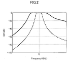
FIG. 2 is a simulation result of comparing the first embodiment of the present invention to a conventional example. -
FIG. 3 is an exploded perspective view illustrating a dielectric waveguide input/output coupling structure according to a second embodiment of the present invention. -
FIG. 4 is a simulation result of comparing the second embodiment to the first embodiment of the present invention. -
FIG. 5 is an exploded perspective view illustrating an example of a conventional dielectric waveguide input/output coupling structure. - A dielectric waveguide input/output coupling structure of the present invention will now be described with reference to the drawings.
-
FIG. 1 is an exploded perspective view of a dielectric waveguide input/output coupling structure according to a first embodiment of the present invention, showing a case of adielectric waveguide 10 mounted on a surface of a printedcircuit board 40. InFIG. 1 , a region exposing the dielectric body is slashed. - As illustrated in
FIG. 1 , thedielectric waveguide 10 comprises a rectangular parallelepiped-shaped dielectric body having an exterior coated with an electrically conductive film. - The
dielectric waveguide 10 has aside surface 10a provided with acoupling window 20 exposing the dielectric body in an approximately quadrangular shape, for coupling to other dielectric waveguide, and abottom surface 11b provided with aslot 30 exposing the dielectric body in an L-shape. - The
slot 30 is composed of a linear slot which is located near and is parallel to aside surface 10b, and a linear slot which is located near and is parallel to aside surface 10c, crossing with each other at a right angle near the corner between theside surfaces - The printed
circuit board 40 has a front surface-side ground pattern 50 provided on an approximately entire front surface of asubstrate 70, and a back surface-side ground pattern 60 provided on an approximately entire back surface of thesubstrate 70. - In the front surface-
side ground pattern 50, there is provided anopening 51 exposing thesubstrate 70 in approximately the same shape as theslot 30 at a position opposed to theslot 30, and in the back surface-side ground pattern 60, there is provided astrip line 61 crossing through the opening 51 from inside to outside of the corner of the opening 51 in spaced-apart relation to the back surface-side ground pattern 60. Thestrip line 61 crosses at a position having approximately equal distances along the L-shape from each of opposite ends of theopening 51. - A distal end of the
strip line 61 and the front surface-side ground pattern 50 are coupled together by avia hole 71. - The opening 51 is surrounded in an approximately quadrangular shape by a
via hole group 80 which couples the front surface-side ground pattern 50 and the back surface-side ground pattern 60 together. Hereinafter, the region surrounded by the via hole group is referred to as a surrounded region. - In general, a dielectric resonator has an electrical field intensity which becomes stronger concentrically from the center thereof when viewed from the top. In the
dielectric waveguide 10, the closer to theside surfaces shaped slot 30 formed by two linear slots crossing with each other near the corner between theside surfaces side surfaces adjacent side surfaces strip line 61 which crosses with theslot 30 in a planar view. As a result, it becomes possible to increase the degree of coupling between the slot and the strip line, allowing for a wider bandwidth. -
FIG. 2 is a graph illustrating a result of simulation and comparison of characteristics between the dielectric waveguide input/output coupling structure of this embodiment and the conventional dielectric waveguide input/output coupling structure. - In
FIG. 2 , the vertical axis represents an insertion loss, the horizontal axis represents a frequency, and the dashed line and the solid line represent the conventional dielectric waveguide input/output coupling structure and the dielectric waveguide input/output coupling structure of the first embodiment, respectively. - The result of
FIG. 2 shows that the dielectric waveguide input/output coupling structure of the present invention has more than three times wider band characteristics as compared to the conventional dielectric waveguide input/output coupling structure. - In the embodiment described above, the
slot 30 may be provided while being aligned with any two adjacent surfaces except for theside surface 10a having thecoupling window 20. That is, theslot 30 may be disposed while being aligned with theside surfaces side surfaces - Further, in the dielectric waveguide input/output coupling structure described above, the outer shapes of the
opening 51 and theslot 30 are approximately the same, but in an actual case, the outer shape of theopening 51 is determined by the shape defined by outer shapes of theopening 51 and theslot 30 overlapping with each other. Therefore, by having an outer shape of theopening 51 which is slightly larger than that of theslot 30, it is possible to minimize degradation of characteristics due to misalignment occurring in mounting the dielectric waveguide on the printed circuit board. - In the first embodiment, in order to achieve a larger bandwidth of the input/output coupling structure, the slot size must be made larger to some extent, and accordingly, the surrounded region must also be made larger. However, large surrounded
region 90 causes reduction in resonant frequency thereof to get close to a resonant frequency f0 of thedielectric waveguide 10, which adversely affects frequency characteristics on higher frequency side of the dielectric waveguide. -
FIG. 3 is an exploded perspective view of a dielectric waveguide input/output coupling structure according to a second embodiment of the present invention. In this embodiment, the shape of surrounded region is modified from the embodiment inFIG. 1 . InFIG. 3 , like reference numerals are applied to the same parts and portions as inFIG. 1 , and detailed description thereof will be omitted. - As illustrated in
FIG. 3 , the surrounded region 91 is chamfered at one corner which is opposed to the L-shaped corner of the approximately quadrangularshaped slot 30. -
FIG. 4 is a graph illustrating a result of simulation of characteristics of the dielectric waveguide input/output coupling structure as illustrated inFIG. 3 . InFIG. 4 , the vertical axis represents an insertion loss, the horizontal axis represents a frequency, and the solid line and the dashed line represent the dielectric waveguide input/output coupling structure of the second embodiment and the dielectric waveguide input/output coupling structure of the first embodiment for comparison, respectively. - As is obvious from
FIG. 4 , the dielectric waveguide input/output coupling structure of this embodiment has a frequency characteristic which is steep on higher frequency side, as compared to the dielectric waveguide input/output coupling structure of the first embodiment. - It is believed that this is because effect of resonance in the surrounded region could be reduced.
- In this way, by the surrounded region having a shape chamfered at one corner of the approximately quadrangular shape, the characteristic of the dielectric waveguide input/output coupling structure can be improved.
- As described above, the present invention makes it possible to provide a dielectric waveguide input/output coupling structure which exhibits large degree of coupling and wideband characteristics.
- Although embodiments of the present invention has been described, it should be understood that the present invention is not intended to be limited to the embodiments described above, and various modifications and substitutions may be made without departing from the scope of the present invention.
- For example, a coupling window is used in the dielectric waveguide as a coupling portion for coupling to other dielectric waveguide, but the coupling portion is not limited to the coupling window. A dielectric plate having a different permittivity (dielectric constant) than that of a dielectric waveguide may be used. Further, grooves may be provided in both side surfaces of a rod-like dielectric body to integrally form a dielectric waveguide with other dielectric waveguide.
-
- 1, 10: dielectric waveguide
- 4, 40: printed circuit board
- 5, 50: front surface-side ground pattern
- 6, 60: back surface-side ground pattern
- 7, 70: substrate
- 3, 5a: electrode
- 30: slot
- 51: opening
- 6a: 61: strip line
- 7a, 71: via hole
- 80: via hole group
- 90, 91: surrounded region
Claims (4)
- A dielectric waveguide input/output coupling structure for coupling an electrode of a dielectric waveguide and a strip line on a printed circuit board together, the dielectric waveguide being configured to be coupled to other dielectric waveguide, wherein:the dielectric waveguide comprises an approximately rectangular parallelepiped-shaped dielectric body having an exterior coated with an electrically conductive film, and has one side surface having a coupling region for coupling to other dielectric waveguide, and a bottom surface having a slot for exposing the dielectric body in an L-shape, the L-shape being formed by two linear slots crossing with each other at their end portions, each of the linear slots being parallel to respective one of two adjacent side surfaces, except for the one side surface, of the dielectric waveguide;the printed circuit board has a front surface having a front surface-side ground pattern provided at a position opposed to the slot, which includes an opening having an outer shape greater than that of the slot, and a back surface having a back surface-side ground pattern and a strip line surrounded by the back surface-side ground pattern and disposed to cross through the slot, andwherein a distal end of the strip line and the front surface-side ground pattern are coupled together by a via hole, the opening is surrounded by a via hole group which couples the front surface-side ground pattern and the back surface-side ground pattern together, and the dielectric waveguide is disposed in such a manner as to allow the opening and the slot to be opposed to each other.
- The dielectric waveguide input/output coupling structure as defined in claim 1, wherein the strip line and the slot cross with each other at a position having approximately equal distances along the opening from each of opposite ends of the slot.
- The dielectric waveguide input/output coupling structure as defined in claims 1 or 2, wherein the via hole is located near the slot.
- The dielectric waveguide input/output coupling structure as defined in any one of the preceding claims, wherein the via hole group surrounds the opening in a triangular shape formed by chamfering one comer of a quadrangular shape.
Applications Claiming Priority (2)
| Application Number | Priority Date | Filing Date | Title |
|---|---|---|---|
| JP2015142733 | 2015-07-17 | ||
| JP2016084096A JP6274248B2 (en) | 2015-07-17 | 2016-04-20 | Input / output connection structure of dielectric waveguide |
Publications (1)
| Publication Number | Publication Date |
|---|---|
| EP3118928A1 true EP3118928A1 (en) | 2017-01-18 |
Family
ID=56418349
Family Applications (1)
| Application Number | Title | Priority Date | Filing Date |
|---|---|---|---|
| EP16001577.2A Withdrawn EP3118928A1 (en) | 2015-07-17 | 2016-07-15 | Input/output coupling structure of dielectric waveguide |
Country Status (3)
| Country | Link |
|---|---|
| US (1) | US9893405B2 (en) |
| EP (1) | EP3118928A1 (en) |
| CN (1) | CN106356601B (en) |
Citations (4)
| Publication number | Priority date | Publication date | Assignee | Title |
|---|---|---|---|---|
| JP2000049506A (en) | 1998-07-31 | 2000-02-18 | Toko Inc | Method for adjusting characteristic of dielectric filter |
| WO2001084665A1 (en) * | 2000-04-28 | 2001-11-08 | Motorola, Inc. | Filtering device and method |
| JP2002043807A (en) * | 2000-07-31 | 2002-02-08 | Sharp Corp | Waveguide-type dielectric filter |
| US20120206213A1 (en) * | 2011-01-13 | 2012-08-16 | Toko, Inc. | Input/Output Coupling Structure for Dielectric Waveguide |
Family Cites Families (12)
| Publication number | Priority date | Publication date | Assignee | Title |
|---|---|---|---|---|
| US5471181A (en) * | 1994-03-08 | 1995-11-28 | Hughes Missile Systems Company | Interconnection between layers of striplines or microstrip through cavity backed slot |
| JP2661568B2 (en) | 1994-11-14 | 1997-10-08 | 日本電気株式会社 | Waveguide-to-plane line converter |
| JP2001136003A (en) * | 1999-11-05 | 2001-05-18 | Murata Mfg Co Ltd | Dielectric filter, dielectric duplexer and communication unit |
| DE60009874T2 (en) * | 2000-05-26 | 2005-03-31 | Sony International (Europe) Gmbh | V-slot antenna for circular polarization |
| KR100387235B1 (en) * | 2000-08-10 | 2003-06-12 | 삼성전자주식회사 | Resonator |
| JP2004187224A (en) * | 2002-12-06 | 2004-07-02 | Toko Inc | Input/output coupling structure for dielectric waveguide resonator |
| KR100706024B1 (en) * | 2005-10-19 | 2007-04-12 | 한국전자통신연구원 | Wide bandwidth microstripe-waveguide transition structure at millimeter wave band |
| TWI335101B (en) * | 2007-06-27 | 2010-12-21 | Ind Tech Res Inst | Vertical coupling structure for non-adjacent resonators |
| CN202308231U (en) * | 2011-11-04 | 2012-07-04 | 浙江嘉康电子股份有限公司 | TEM die coaxial medium ceramic filter |
| WO2013189072A1 (en) * | 2012-06-21 | 2013-12-27 | Telefonaktiebolaget L M Ericsson (Publ) | Bandpass filter and method of fabricating the same |
| JP2016072881A (en) * | 2014-09-30 | 2016-05-09 | 日本電産エレシス株式会社 | High frequency power conversion mechanism |
| JP2016225894A (en) * | 2015-06-02 | 2016-12-28 | 東光株式会社 | Dielectric waveguide filter and dielectric waveguide duplexer |
-
2016
- 2016-07-15 CN CN201610560032.6A patent/CN106356601B/en active Active
- 2016-07-15 EP EP16001577.2A patent/EP3118928A1/en not_active Withdrawn
- 2016-07-15 US US15/211,185 patent/US9893405B2/en active Active
Patent Citations (4)
| Publication number | Priority date | Publication date | Assignee | Title |
|---|---|---|---|---|
| JP2000049506A (en) | 1998-07-31 | 2000-02-18 | Toko Inc | Method for adjusting characteristic of dielectric filter |
| WO2001084665A1 (en) * | 2000-04-28 | 2001-11-08 | Motorola, Inc. | Filtering device and method |
| JP2002043807A (en) * | 2000-07-31 | 2002-02-08 | Sharp Corp | Waveguide-type dielectric filter |
| US20120206213A1 (en) * | 2011-01-13 | 2012-08-16 | Toko, Inc. | Input/Output Coupling Structure for Dielectric Waveguide |
Non-Patent Citations (3)
| Title |
|---|
| HUNG-YI CHIEN ET AL: "Miniaturized Bandpass Filters With Double-Folded Substrate Integrated Waveguide Resonators in LTCC", IEEE TRANSACTIONS ON MICROWAVE THEORY AND TECHNIQUES, IEEE SERVICE CENTER, PISCATAWAY, NJ, US, vol. 57, no. 7, 1 July 2009 (2009-07-01), pages 1774 - 1782, XP011261771, ISSN: 0018-9480 * |
| TOKO: "Dielectric Waveguide Filters - Type WDFM", 1 January 2013 (2013-01-01), pages 1 - 1, XP055322499, Retrieved from the Internet <URL:http://bec.co.uk/downloads/wdfm.pdf> [retrieved on 20161124] * |
| TOKO: "General Catalog", 1 January 2013 (2013-01-01), pages 1 - 28, XP055322497, Retrieved from the Internet <URL:http://bec.co.uk/wp-content/uploads/2015/01/TOKO-General-Catalog-2013.pdf> [retrieved on 20161124] * |
Also Published As
| Publication number | Publication date |
|---|---|
| CN106356601B (en) | 2020-01-17 |
| US9893405B2 (en) | 2018-02-13 |
| CN106356601A (en) | 2017-01-25 |
| US20170018834A1 (en) | 2017-01-19 |
Similar Documents
| Publication | Publication Date | Title |
|---|---|---|
| CN108398665B (en) | Radar assembly with ultra-wideband waveguide for substrate integrated waveguide conversion | |
| US8089327B2 (en) | Waveguide to plural microstrip transition | |
| EP1592082B1 (en) | Contact-free element of transition between a waveguide and a microstrip line | |
| KR101089195B1 (en) | Input/output coupling structure for dielectric waveguide | |
| US9166300B2 (en) | Slot antenna | |
| EP1990863A1 (en) | Dual band resonator and dual band filter | |
| US7821361B2 (en) | Second-order band-pass filter and wireless apparatus using the same | |
| CN109478705B (en) | Coaxial-waveguide converter | |
| WO2002058185A1 (en) | High frequency circuit element and high frequency circuit module | |
| CN111193088B (en) | Branch line coupler | |
| KR100586502B1 (en) | A dielectric ceramic filter with a metal guide-can | |
| MXPA05006079A (en) | Finline type microwave band-pass filter. | |
| KR101754278B1 (en) | Tem mode dielectric waveguide resonator and dielectric waveguide filter using the same | |
| US9893405B2 (en) | Input/output coupling structure of dielectric waveguide | |
| US20020003456A1 (en) | Antenna duplexer and communication apparatus | |
| KR100521895B1 (en) | Lowpass Filter Using CPW Structure with Inductive Etched Hole | |
| US20160006094A1 (en) | Cross coupled band-pass filter | |
| JP2008079085A (en) | Transmission line waveguide converter | |
| CN115207589A (en) | Coupling device, manufacturing method, waveguide antenna, radar, terminal and PCB | |
| EP1581980B1 (en) | Waveguide e-plane rf bandpass filter with pseudo-elliptic response | |
| JP2007295361A (en) | Duplexer | |
| JP2006081160A (en) | Transmission path converter | |
| JP3988498B2 (en) | Waveguide filter | |
| JP6274248B2 (en) | Input / output connection structure of dielectric waveguide | |
| JP4795225B2 (en) | Dielectric waveguide slot antenna |
Legal Events
| Date | Code | Title | Description |
|---|---|---|---|
| PUAI | Public reference made under article 153(3) epc to a published international application that has entered the european phase |
Free format text: ORIGINAL CODE: 0009012 |
|
| AK | Designated contracting states |
Kind code of ref document: A1 Designated state(s): AL AT BE BG CH CY CZ DE DK EE ES FI FR GB GR HR HU IE IS IT LI LT LU LV MC MK MT NL NO PL PT RO RS SE SI SK SM TR |
|
| AX | Request for extension of the european patent |
Extension state: BA ME |
|
| RAP1 | Party data changed (applicant data changed or rights of an application transferred) |
Owner name: MURATA MANUFACTURING CO., LTD. |
|
| 17P | Request for examination filed |
Effective date: 20170718 |
|
| RBV | Designated contracting states (corrected) |
Designated state(s): AL AT BE BG CH CY CZ DE DK EE ES FI FR GB GR HR HU IE IS IT LI LT LU LV MC MK MT NL NO PL PT RO RS SE SI SK SM TR |
|
| 17Q | First examination report despatched |
Effective date: 20171201 |
|
| GRAJ | Information related to disapproval of communication of intention to grant by the applicant or resumption of examination proceedings by the epo deleted |
Free format text: ORIGINAL CODE: EPIDOSDIGR1 |
|
| GRAP | Despatch of communication of intention to grant a patent |
Free format text: ORIGINAL CODE: EPIDOSNIGR1 |
|
| GRAP | Despatch of communication of intention to grant a patent |
Free format text: ORIGINAL CODE: EPIDOSNIGR1 |
|
| RIC1 | Information provided on ipc code assigned before grant |
Ipc: H01P 5/107 20060101AFI20180703BHEP Ipc: H01P 3/12 20060101ALN20180703BHEP |
|
| RIC1 | Information provided on ipc code assigned before grant |
Ipc: H01P 3/12 20060101ALN20180709BHEP Ipc: H01P 5/107 20060101AFI20180709BHEP |
|
| INTG | Intention to grant announced |
Effective date: 20180801 |
|
| STAA | Information on the status of an ep patent application or granted ep patent |
Free format text: STATUS: THE APPLICATION IS DEEMED TO BE WITHDRAWN |
|
| 18D | Application deemed to be withdrawn |
Effective date: 20181212 |