EP3118893A1 - An apparatus and method for enabling transfer of two dimensional materials - Google Patents
An apparatus and method for enabling transfer of two dimensional materials Download PDFInfo
- Publication number
- EP3118893A1 EP3118893A1 EP15176522.9A EP15176522A EP3118893A1 EP 3118893 A1 EP3118893 A1 EP 3118893A1 EP 15176522 A EP15176522 A EP 15176522A EP 3118893 A1 EP3118893 A1 EP 3118893A1
- Authority
- EP
- European Patent Office
- Prior art keywords
- layer
- dimensional material
- examples
- coefficient
- thermal expansion
- Prior art date
- Legal status (The legal status is an assumption and is not a legal conclusion. Google has not performed a legal analysis and makes no representation as to the accuracy of the status listed.)
- Withdrawn
Links
Images



Classifications
-
- H—ELECTRICITY
- H10—SEMICONDUCTOR DEVICES; ELECTRIC SOLID-STATE DEVICES NOT OTHERWISE PROVIDED FOR
- H10P—GENERIC PROCESSES OR APPARATUS FOR THE MANUFACTURE OR TREATMENT OF DEVICES COVERED BY CLASS H10
- H10P72/00—Handling or holding of wafers, substrates or devices during manufacture or treatment thereof
- H10P72/04—Apparatus for manufacture or treatment
- H10P72/0428—Apparatus for mechanical treatment or grinding or cutting
-
- H—ELECTRICITY
- H10—SEMICONDUCTOR DEVICES; ELECTRIC SOLID-STATE DEVICES NOT OTHERWISE PROVIDED FOR
- H10P—GENERIC PROCESSES OR APPARATUS FOR THE MANUFACTURE OR TREATMENT OF DEVICES COVERED BY CLASS H10
- H10P72/00—Handling or holding of wafers, substrates or devices during manufacture or treatment thereof
- H10P72/04—Apparatus for manufacture or treatment
- H10P72/0451—Apparatus for manufacturing or treating in a plurality of work-stations
- H10P72/0468—Apparatus for manufacturing or treating in a plurality of work-stations comprising a chamber adapted to a particular process
-
- H—ELECTRICITY
- H10—SEMICONDUCTOR DEVICES; ELECTRIC SOLID-STATE DEVICES NOT OTHERWISE PROVIDED FOR
- H10P—GENERIC PROCESSES OR APPARATUS FOR THE MANUFACTURE OR TREATMENT OF DEVICES COVERED BY CLASS H10
- H10P72/00—Handling or holding of wafers, substrates or devices during manufacture or treatment thereof
- H10P72/30—Handling or holding of wafers, substrates or devices during manufacture or treatment thereof for conveying, e.g. between different workstations
- H10P72/33—Handling or holding of wafers, substrates or devices during manufacture or treatment thereof for conveying, e.g. between different workstations into and out of processing chamber
- H10P72/3314—Continuous loading and unloading into and out of a processing chamber, e.g. transporting belts within processing chambers
-
- H—ELECTRICITY
- H10—SEMICONDUCTOR DEVICES; ELECTRIC SOLID-STATE DEVICES NOT OTHERWISE PROVIDED FOR
- H10P—GENERIC PROCESSES OR APPARATUS FOR THE MANUFACTURE OR TREATMENT OF DEVICES COVERED BY CLASS H10
- H10P72/00—Handling or holding of wafers, substrates or devices during manufacture or treatment thereof
- H10P72/70—Handling or holding of wafers, substrates or devices during manufacture or treatment thereof for supporting or gripping
- H10P72/74—Handling or holding of wafers, substrates or devices during manufacture or treatment thereof for supporting or gripping using temporarily an auxiliary support
-
- H—ELECTRICITY
- H10—SEMICONDUCTOR DEVICES; ELECTRIC SOLID-STATE DEVICES NOT OTHERWISE PROVIDED FOR
- H10P—GENERIC PROCESSES OR APPARATUS FOR THE MANUFACTURE OR TREATMENT OF DEVICES COVERED BY CLASS H10
- H10P90/00—Preparation of wafers not covered by a single main group of this subclass, e.g. wafer reinforcement
- H10P90/19—Preparing inhomogeneous wafers
- H10P90/1904—Preparing vertically inhomogeneous wafers
- H10P90/1906—Preparing SOI wafers
- H10P90/1914—Preparing SOI wafers using bonding
-
- H—ELECTRICITY
- H10—SEMICONDUCTOR DEVICES; ELECTRIC SOLID-STATE DEVICES NOT OTHERWISE PROVIDED FOR
- H10W—GENERIC PACKAGES, INTERCONNECTIONS, CONNECTORS OR OTHER CONSTRUCTIONAL DETAILS OF DEVICES COVERED BY CLASS H10
- H10W10/00—Isolation regions in semiconductor bodies between components of integrated devices
- H10W10/10—Isolation regions comprising dielectric materials
- H10W10/181—Semiconductor-on-insulator [SOI] isolation regions, e.g. buried oxide regions of SOI wafers
-
- H—ELECTRICITY
- H10—SEMICONDUCTOR DEVICES; ELECTRIC SOLID-STATE DEVICES NOT OTHERWISE PROVIDED FOR
- H10P—GENERIC PROCESSES OR APPARATUS FOR THE MANUFACTURE OR TREATMENT OF DEVICES COVERED BY CLASS H10
- H10P72/00—Handling or holding of wafers, substrates or devices during manufacture or treatment thereof
- H10P72/70—Handling or holding of wafers, substrates or devices during manufacture or treatment thereof for supporting or gripping
- H10P72/74—Handling or holding of wafers, substrates or devices during manufacture or treatment thereof for supporting or gripping using temporarily an auxiliary support
- H10P72/7426—Handling or holding of wafers, substrates or devices during manufacture or treatment thereof for supporting or gripping using temporarily an auxiliary support used as a support during build up manufacturing of active devices
-
- H—ELECTRICITY
- H10—SEMICONDUCTOR DEVICES; ELECTRIC SOLID-STATE DEVICES NOT OTHERWISE PROVIDED FOR
- H10P—GENERIC PROCESSES OR APPARATUS FOR THE MANUFACTURE OR TREATMENT OF DEVICES COVERED BY CLASS H10
- H10P72/00—Handling or holding of wafers, substrates or devices during manufacture or treatment thereof
- H10P72/70—Handling or holding of wafers, substrates or devices during manufacture or treatment thereof for supporting or gripping
- H10P72/74—Handling or holding of wafers, substrates or devices during manufacture or treatment thereof for supporting or gripping using temporarily an auxiliary support
- H10P72/7434—Handling or holding of wafers, substrates or devices during manufacture or treatment thereof for supporting or gripping using temporarily an auxiliary support used in a transfer process involving at least two transfer steps, i.e. including an intermediate handle substrate
-
- H—ELECTRICITY
- H10—SEMICONDUCTOR DEVICES; ELECTRIC SOLID-STATE DEVICES NOT OTHERWISE PROVIDED FOR
- H10P—GENERIC PROCESSES OR APPARATUS FOR THE MANUFACTURE OR TREATMENT OF DEVICES COVERED BY CLASS H10
- H10P72/00—Handling or holding of wafers, substrates or devices during manufacture or treatment thereof
- H10P72/70—Handling or holding of wafers, substrates or devices during manufacture or treatment thereof for supporting or gripping
- H10P72/74—Handling or holding of wafers, substrates or devices during manufacture or treatment thereof for supporting or gripping using temporarily an auxiliary support
- H10P72/744—Details of chemical or physical process used for separating the auxiliary support from a device or a wafer
Definitions
- Examples of the disclosure relate to apparatus and methods for enabling transfer of two dimensional materials. In particular they relate to apparatus and methods for releasing two dimensional materials from a substrate.
- Two dimensional materials such as graphene, hexagonal boron nitride, molybdenum disulphide or other materials can be used in microelectronic devices such as thin film transistors, transducers, sensors or other applications.
- the two dimensional material may be grown on growth substrate and then transferred to a target substrate.
- An intermediate substrate may be used to transfer the two dimensional material from the growth substrate to the target substrate.
- the two dimensional materials are very thin it can be very difficult to transfer the two dimensional material between different substrates without contaminating or doping or otherwise damaging the two dimensional material.
- an apparatus comprising: a first layer having a first coefficient of thermal expansion and configured to support a layer of two dimensional material; a second layer, coupled to the first layer, having a second coefficient of thermal expansion; wherein the first coefficient of thermal expansion is different to the second coefficient of thermal expansion such that a change in temperature causes deformation of at least part of the apparatus and the deformation enables transfer of the two dimensional material.
- the transfer of the two dimensional material may comprise removing the first layer and the layer of two dimensional material from the second layer.
- the transfer of the two dimensional material may comprise removing the layer of two dimensional material from the first layer.
- the deformation may comprise a progressive bending of one or more layers of the apparatus which enables one or more layers of the apparatus to be separated from other layers.
- the deformation may comprise a progressive bending of the first layer.
- the deformation may comprise a progressive bending of the second layer.
- increasing the temperature of the apparatus may cause the apparatus to bend in a first direction and decreasing the temperature causes the apparatus to bend in a second direction.
- increasing the temperature of the apparatus may cause the apparatus to bend in a first direction and further increasing the temperature causes the apparatus to bend in a second direction.
- first layer and the second layer may have different glass transition temperatures.
- the change in temperature may be applied locally to a portion of the apparatus.
- the apparatus may comprise more than two layers.
- the apparatus may be used in roll to roll manufacturing.
- a method comprising: providing a layer of two dimensional material on a first layer of an apparatus, wherein the apparatus comprises a first layer having a first coefficient of thermal expansion and a second layer, coupled to the first layer, having a second coefficient of thermal expansion wherein the first coefficient of thermal expansion is different to the second coefficient of thermal expansion; and changing the temperature so that the difference in the coefficients of thermal expansion causes deformation of at least part of the apparatus and the deformation enables transfer of the two dimensional material.
- the transfer of the two dimensional material may comprise removing the first layer and the layer of two dimensional material from the second layer.
- the transfer of the two dimensional material may comprise removing the layer of two dimensional material from the first layer.
- the deformation may comprise a progressive bending of one or more layers of the apparatus which enables one or more layers of the apparatus to be separated from other layers.
- the deformation may comprise a progressive bending of the first layer.
- the deformation may comprise a progressive bending of the second layer.
- increasing the temperature of the apparatus may cause the apparatus to bend in a first direction and decreasing the temperature causes the apparatus to bend in a second direction.
- increasing the temperature of the apparatus may cause the apparatus to bend in a first direction and further increasing the temperature causes the apparatus to bend in a second direction.
- first layer and the second layer may have different glass transition temperatures.
- the change in temperature may be applied locally to a portion of the apparatus.
- the apparatus may comprise more than two layers.
- the method may be used in roll to roll manufacturing.
- the figures illustrate an apparatus 1 comprising: a first layer 3 having a first coefficient of thermal expansion and configured to support a layer of two dimensional material 7; a second layer 5, coupled to the first layer 3, having a second coefficient of thermal expansion; wherein the first coefficient of thermal expansion is different to the second coefficient of thermal expansion such that a change in temperature causes deformation of at least part of the apparatus 1 and the deformation enables transfer of the two dimensional material 7.
- the apparatus 1 may be for transferring a layer of two dimensional material from a first substrate to a second, different substrate.
- the apparatus 1 may be for releasing a two dimensional material from a growth substrate and/or transferring the two dimensional material to a target substrate.
- Fig. 1 schematically illustrates an apparatus 1 according to examples of the disclosure.
- the apparatus 1 comprises a first layer 3 and a second layer 5.
- the first layer 3 is configured to support a layer of two dimensional material 7.
- the first layer 3 is provided overlaying the second layer 5 so that the first and second layers 3, 5 form a laminar structure. It is to be appreciated that the apparatus 1 could also be provided with the second layer 5 overlaying the first layer 3.
- the two dimensional material 7 is provided on a surface of the first layer 3.
- the two dimensional material 7 is provided on a first surface of the first layer 3 and the second layer 5 is coupled to the opposite surface of the first layer 3.
- the layer of two dimensional material 7 may comprise a very thin layer of material.
- the layer of two dimensional material 7 could be an atomic monolayer.
- the layer of two dimensional material 7 could comprise several atomic monolayers.
- the layer of two dimensional material could comprise graphene, molybdenum disulphide, boron nitride or any other suitable material.
- the first layer 3 and the second layer 5 are coupled together.
- the first and second layers 3, 5 may be bonded together.
- the bonds may comprise Van der Waals bonds.
- first layer 3 may be coupled to the second layer 5 so that deformation of one of the layers 3, 5 also causes deformation of the other layer 5, 3.
- first layer 3 may be coupled to the second layer 5 such that deformation of one of the layers 3, 5 enables the first and second layers 3, 5 to be separated.
- the first layer 3 is coupled directly to the second layer 5. There are no intervening components between the first layer 3 and the second layer 5. In other examples one or more intervening components may be provided between the first layer 3 and the second layer 5. For instance, in some examples the apparatus 1 may comprise more than two layers 3, 5. In such examples one or more intervening layers could be provided between the first layer 3 and the second layer 5.
- the first layer 3 has a first coefficient of thermal expansion and the second layer 5 has a second coefficient of thermal expansion.
- the materials that are used for the different layers 3, 5 may be selected so that the second coefficient of thermal expansion is different to the first coefficient of thermal expansion.
- the difference in coefficient of thermal expansions between the two layers may be arranged such that when the temperature of the apparatus 1 is changed the apparatus 1, or at least part of the apparatus, is deformed. The deformation of the apparatus 1 may enable the two dimensional material to be transferred between substrates.
- Fig. 1 illustrates the apparatus 1 in an un-deformed state.
- each of the layers In the un-deformed state each of the layers is flat or substantially flat. If the temperature of the apparatus 1, or at least part of the apparatus 1, is changed this will cause deformation of the apparatus 1. In some examples the change in temperature may cause all of the apparatus 1 to deform. In other examples the change in temperature may only cause part of the apparatus 1 to deform.
- the first layer 3 and the second layer 5 may comprise any suitable materials.
- the materials may be chosen so that the deformation of the apparatus 1 required to transfer the two dimensional material 7 occurs at a particular temperature.
- the materials used for the first layer 3 and the second layer 5 may be selected so that the two layers have a different glass transition temperature. As a material has a much smaller Young's modulus above the glass transition temperature this will cause a large reduction in the modulus for one of the layers 3, but not for the other layer. The material will also increase the coefficient of thermal expansion above the glass transition temperature. This will increase the differences in coefficient of thermal expansions at given temperatures. This property of the materials may be used to control the deformation of the apparatus 1.
- the materials that are used for the respective layers 3, 5 of the apparatus 1 may be selected to have particular glass transition temperatures.
- the glass transition temperatures may enable the deformation of the apparatus 1 to be controlled so that the deformation occurs at specific temperatures and/or at specific locations within the apparatus 1.
- the materials used for the layers 3, 5 may be uniform so that the glass transition temperature is uniform throughout the material.
- the material may be non-uniform so that different sides of a layer 3, 5 may have different glass transition temperatures. This may enable the deformation of the apparatus 1 to be controlled by controlling the temperature.
- first and second layers 3, 5 may comprise materials such as polydimethylsiloxane (PDMS), Polyurethane, Polyethylene Naphthalate (PEN), Polyethylene terephthalate (PET), acrylic, polyimide or any other suitable materials.
- PDMS polydimethylsiloxane
- PEN Polyethylene Naphthalate
- PET Polyethylene terephthalate
- acrylic acrylic
- polyimide any other suitable materials.
- the two dimensional material 7 is provided on a surface of the first layer 3.
- the two dimensional material 7 is provided on a first surface of the first layer 3 and the second layer 5 is coupled to the opposite surface of the first layer 3.
- the apparatus 1 may be arranged so that both the first layer 3 and the second layer 5 provide a deformable substrate which enables the two dimensional material 7 to be transferred.
- the apparatus 1 may be arranged so that deformation causes the first layer 3 to separate from the second layer 5 so that only the first layer 3 supports the two dimensional material as it is being transferred.
- the two dimensional material could be provided between the first layer 3 and the second layer 5.
- the deformation of the apparatus 1 may enable the first layer 3 to separate from the second layer 5 which may enable the two dimensional material 7 to be transferred from the first layer 3 to the second layer 5.
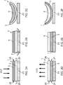
- Figs. 2A to 2F illustrate two example apparatus 1 in use.
- Figs. 2A to 2C illustrate a first example apparatus 1 attached to a substrate 21.
- Figs. 2D to 2F illustrate a second example apparatus 1 attached to a substrate 21.
- the substrate 21 could be a growth substrate.
- the growth substrate 21 may comprise any material upon which a layer of two dimensional material 7 can be fabricated.
- the growth substrate 21 could comprise a layer of copper.
- the apparatus 1 may be used to remove a layer of two dimensional material 7 from the substrate 21.
- the substrate 21 could be a target substrate.
- the target substrate could comprise a layer which is configured to receive the two dimensional material 7.
- the target substrate could form part of a microelectronic device.
- the target substrate could comprise silicon or any other suitable material.
- the apparatus 1 may be used to transfer the two dimensional material 7 to the substrate 21.
- the apparatus 1 is arranged with the first layer 3 positioned underneath the second layer 5.
- the first layer 3 is provided adjacent to the substrate 21 and the second layer 5 is provided overlaying the first layer 3.
- the second layer 5 has a smaller coefficient of thermal expansion than the first layer 3. That is, the first layer 3, which is adjacent to the substrate 21, has the higher coefficient of thermal expansion.
- Fig. 2A illustrates the apparatus 1 and the substrate 21 in an un-deformed state.
- each of the layers 3, 5 of the apparatus 1 is flat or substantially flat.
- the apparatus 1 may be deformed by changing the temperature of the apparatus 1.
- the apparatus 1 In the example of Fig. 2A the apparatus 1 is heated.
- the heating of the apparatus 1 causes an expansion of the first layer 3 and the second layer 5 as indicated by the arrows 23, 25.
- Fig. 2B shows the apparatus 1 after the temperature has increased.
- the first layer 3 has the higher coefficient of thermal expansion than the second layer 5 the first layer 3 expands more than the second layer 5.
- the substrate 21 has not expanded significantly. This generates stress at the interface between the first layer 3 and the substrate 21.
- Fig. 2C shows the apparatus 1 in a deformed state.
- the apparatus 1 deforms by curling.
- the curling comprises a progressive bending of both the first and second layers 3, 5 of the apparatus 1.
- the apparatus 1 bends away from the substrate 21 which enables the apparatus 1 to be gradually removed from the surface of the substrate 21.
- Figs. 2D to 2F show another example apparatus 1.
- the apparatus 1 is also attached to a substrate 21 however in Figs. 2D to 2F the second layer 5 has the higher coefficient of thermal expansion. That is, the first layer 3, which is adjacent to the substrate 21 has the lower coefficient of thermal expansion.
- Fig. 2D illustrates the apparatus 1 and the substrate 21 in an un-deformed state.
- each of the layers 3, 5 of the apparatus 1 is flat or substantially flat.
- the apparatus 1 may be deformed by changing the temperature of the apparatus 1.
- the apparatus 1 In the example of Fig. 2D the apparatus 1 is cooled.
- the cooling of the apparatus1 causes contraction of the first layer 3 and the second layer 5 as indicated by the arrows 27, 29.
- Fig. 2E shows the apparatus 1 after it has been cooled.
- the second layer 5 has the higher coefficient of thermal expansion the second layer 5 contracts more than the first layer 3. This generates stress at the interface between the first layer 3 and the second layer 5 which causes the apparatus 1 to deform.
- the stress generated between the first layer 3 and the substrate 21 in the example of Fig. 2E may be lower that the stress generated between the first layer 3 and the substrate 21 in the example of Fig. 2B .
- Fig. 2F shows the apparatus 1 in a deformed state.
- the apparatus 1 also deforms by curling.
- the curling comprises a progressive bending of both the first and second layers 3, 5 of the apparatus 1.
- the apparatus 1 bends away from the substrate 21 which enables the apparatus 1 to be gradually removed from the surface of the substrate 21.
- both the first layer 3 and the second layer 5 are deformed. In other examples only one of the layers might be deformed. Also in the examples of Figs. 2A to 2F all of the apparatus 1 is deformed. In other examples only a part of the apparatus 1 might be deformed. For instance a temperature change might be applied locally to enable part of an apparatus 1 to be deformed.
- the radius of curvature of the apparatus 1 when it is deformed is determined by the difference in coefficients of the thermal expansion of the respective layers 3, 5 and the Young's modulus of the materials.
- the differences in the strains cause the apparatus 1 to deform so that the stresses within the apparatus 1 are balanced.
- the radius of curvature of a bilayer apparatus 1 is given by equation 3 where E' is the lateral Youngs modulus, w and t are the width and thickness of the two materials respectively and r is the radius of curvature.
- E' is the lateral Youngs modulus
- w and t are the width and thickness of the two materials respectively
- r is the radius of curvature.
- equation 3 covers a simple case and assumes that the Young's modulus remains constant, that the apparatus 1 is free standing and the layers of the apparatus 1 are uniformly heated. However it can be seen from this equation that the curvature of the apparatus 1 is proportional to the difference in thermal coefficients of two adjacent layers.
- the apparatus 1 is heated to or above the glass transition temperature of one of the layers 3, 5 this will greatly reduce the Young's modulus and increase the thermal coefficient of expansion of that layer 3, 5. This change in the Young's modulus and thermal coefficient of expansion can enable a greater deformation of the apparatus 1.
- the deformation of the apparatus 1 may be controlled by locally cooling or heating regions of the apparatus 1 with thin strips of jetted hot or cold air.
- the strips of air will cause a local change in temperature of a part of the apparatus 1.
- the different coefficients of thermal expansion will cause local deformation of the apparatus 1.
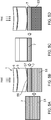
- Figs. 3A to 3C illustrate another example apparatus 1 in use.
- the example of Figs. 3A to 3C differs from the example of Figs. 2A to 2F in that in the previous examples both layers of the apparatus 1 were deformed whereas in the example of Figs. 3A to 3C only one of the layers is deformed.
- a second layer 5 of the apparatus 1 is formed.
- the second layer 5 comprises a support substrate 31.
- the support substrate 31 may provide a rigid or substantially rigid substrate which may provide support while the two dimensional material 7 is being fabricated and/or patterned.
- the support substrate 31 may comprise a silicon wafer or any other suitable material.
- the support substrate 31 may be flat or substantially flat.
- the first layer 3 of the apparatus 1 is provided overlaying the second layer 5.
- the first layer 3 may be coupled to the second layer 5 by Van der Waals bonds or any other suitable means.
- the layer of two dimensional material 7 may be fabricated and/or patterned on the first layer 3.
- the two dimensional material 7 may be fabricated and/or patterned on the surface 33 of the first layer 3.
- the two dimensional material 7 may be formed as microelectronic devices or components of microelectronic devices.
- the two dimensional material 7 could be formed to provide source and drain electrodes and a channel for thin film transistors (TFTs) or any other suitable components of microelectronic devices.
- the two dimensional material 7 may be formed using nano-imprint or photolithography techniques or any other suitable method.
- the first layer 3 may comprise a material which has a higher thermal coefficient of expansion than the second layer 5. In some examples the thermal coefficient of expansion of the first layer 3 may be much great than the thermal coefficient of expansion of the second layer 5. In the examples of Fig. 3B the first layer 3 may be formed from a polymer material such as PEN. It is to be appreciated that other materials may be used in other examples.
- Fig. 3C the apparatus 1 has been heated and is in a deformed state.
- the heating of the apparatus 1 causes the first layer 3 to expand more than the second layer 5.
- the expansion of the first layer 3 is much greater than any expansion of the second layer 5.
- the expansion causes stress at the interface between the first and second layers 3, 5. This stress causes the first layer 3 of the apparatus 1 to deform while the second layer 5 remains flat or substantially flat.
- the deformation of the apparatus 1 comprises the progressive bending of the first layer 3.
- the first layer 3 has curled away from the support substrate 31 provided by second layer 5 while the second layer 5 has remained substantially flat.
- This curling may enable the first layer 3, and the layer of two dimensional material 7 which is supported by the first layer 3, to be removed from the support substrate 31 provided by the second layer 5.
- This may enable the two dimensional material 7 which has been fabricated on the first layer 3 to be transferred to another substrate or device. Therefore the example apparatus 1 of Figs. 3A to 3C enables the transfer of a two dimensional material 7 by removing the first layer 3 and the layer of two dimensional material 7 from the second layer 5.
- the apparatus 1 may be heated to the glass transition temperature of the first layer 3. Above the glass transition temperature the Young's modulus will reduce significantly and the thermal coefficient of expansion of the first layer 3 will increase significantly. This will increase the difference in the thermal coefficient of expansion between the two layers 3, 5. Where a material such as PEN is used as the first layer 3 the glass transition temperature could be around 150°C.
- the two dimensional material 7 can be removed from the wafer by heating the apparatus 1. There is no need for any wet processing of the apparatus 1. This may reduce the likelihood of doping and/or contamination of the two dimensional material 7.
- the apparatus 1 does not need to be heated to a very high temperature.
- PEN is used as the material for the first layer 3
- the apparatus could be heated to a temperature of 150°C. This may be above the glass transition temperature of a material such as PEN and so may be sufficient to cause the deformation of the first layer 3 of the apparatus 1. This temperature may still be low enough to avoid damaging the two dimensional material 7.
- Fig. 4 illustrates another example apparatus 1.
- the apparatus 1 is provided between a support substrate 41 and a target substrate 43.
- the example apparatus 1 of Fig. 4 may be arranged to deform in different directions so as to enable the apparatus 1 to be attached to and released from different substrates.
- the example apparatus 1 of Fig. 4 comprises a first layer 3 and a second layer 5.
- the first layer 3 may comprise a flexible polymer such as PET, PEN or any other suitable material.
- the second layer 5 may comprise a material such as PDMS.
- the first and second layers 3, 5 are coupled together.
- the first layer 3 may be coupled to the second layer 5 by Van der Waals interactions or any other suitable means.
- the second layer 5 of the apparatus 1 is coupled to the support substrate 41.
- the support substrate 41 may provide a rigid support layer while the two dimensional material 7 is being formed.
- the two dimensional material 7 may be formed on the surface of the first layer 3.
- the first layer 3 may then be coupled to the target substrate 43 to enable the two dimensional material 7 to be transferred from the first layer 3 to the target substrate 43.
- the temperature of the apparatus 1 may be changed in order to enable the apparatus 1 to be removed from the support substrate 41 and the target layer 43.
- a first change in temperature may be used to cause a deformation which enables the second layer 5 to be released from the support substrate 41 and a second change in temperature may be used to cause a deformation which enables the first layer 3 to be released from the target substrate 43.
- the apparatus 1 may be deformed in a first direction by decreasing the temperature. This will cause the layer 3, 5 with the largest coefficient of thermal expansion to contract more and may cause the apparatus 1 to bend in a first direction.
- the apparatus 1 could then be deformed in a second direction by increasing the temperature. The heating would cause the layer with the largest coefficient of thermal expansion to expand more and may cause the apparatus 1 to bend in a second direction.
- the second direction could be opposite to the first direction. Therefore by following a heating pattern the apparatus 1 could be removed from both the support substrate 41 and the target substrate 43.
- the apparatus 1 could be heated to enable it to be removed from the support substrate 41. It might then be cooled to enable it to be removed from the target substrate 43. It is to be appreciated that other heating patterns could be used in other examples of the disclosure.
- Figs. 5A to 5D illustrate another example apparatus 1 in use.
- the apparatus 1 enables transfer of a two dimensional material 7 by enabling the layer of two dimensional material 7 to be removed from a growth substrate 51 and then removed from the first layer 3 to a target substrate 53.
- a layer of two dimensional material 7 is grown on the growth substrate 51.
- the growth substrate 51 may comprise any material upon which a layer of two dimensional material 7 can be fabricated.
- the growth substrate 51 could comprise a layer of copper or any other suitable material.
- the layer of two dimensional material 7 could comprise graphene or any other suitable two dimensional material 7.
- FIG. 5B an apparatus 1 is provided overlaying the two dimensional material 7.
- the apparatus 1 comprises a first layer 3 and a second layer 5.
- the apparatus 1 is arranged so that the first layer 3 attaches to the two dimensional layer 7.
- the apparatus 1 is heated before it is positioned overlaying the two dimensional material 7.
- the heating of the apparatus 1 causes the apparatus 1 to curl as shown in Fig. 5B .
- the heated apparatus 1 may then be positioned adjacent the two dimensional material 7.
- the apparatus 1 is initially positioned adjacent the two dimensional material only a first portion 55 of the first layer 3 is in contact with the two dimensional material 7.
- the rest of the first layer 3 is curled upwards so that a gap 57 is provided between the first layer 3 and the two dimensional material 7.
- the apparatus 1 As the apparatus 1 cools it gradually uncurls so that the area 55 of the first layer 3 which is in contact with the two dimensional material 7 gradually increases. As the material uncurls any air bubbles or other pockets of gas between the apparatus 1 and the two dimensional material 7 will be pushed out. This provides for improved lamination of the apparatus 1 and the two dimensional material 7. In some examples this may allow for the apparatus 1 to self laminate with the two dimensional material 7 and the growth substrate 51.
- the apparatus 1 may be heated above the glass transition temperature of the first layer 3. This may also allow for uniform contact across the surface of the two dimensional material 7.
- the growth substrate 51 may be removed.
- Fig. 5C illustrates the apparatus 1 after the growth substrate 51 has been removed.
- the growth substrate 51 may be removed using any suitable method. For instance where the growth substrate 51 comprises copper the growth substrate may be removed by wet etching, electrochemical oxidation or other suitable techniques.
- the apparatus 1 is flat or substantially flat.
- the apparatus 1 may be arranged in the flat configuration before the growth substrate 51 is removed.
- the two dimensional material 7 is left attached to the first layer 3 of the apparatus 1.
- the two dimensional material 7 can then be attached to a target substrate 53.
- Fig. 5D illustrates the apparatus 1 being removed from the target substrate 53.
- the apparatus 1 is heated to cause the first layer 3 to bend away from the two dimensional material 7.
- The enables the controlled release of the first layer 3 from the two dimensional material 7 so that the apparatus 1 may be removed from the layer of two dimensional material 7 leaving the two dimensional material 7 on the target substrate 53.
- the apparatus 1 acts as a transfer substrate and enables a layer of two dimensional material 7 to be removed from a first substrate 51 and attached to another substrate 53.
- the first layer 3 of the apparatus 1 may have the higher coefficient of thermal expansion so that the first layer 3 of the apparatus 1 curls away from the two dimensional material 7 when it is heated but curls towards the two dimensional material 7 when it is cooled.
- Figs. 6A to 6E illustrate an example apparatus 1 in which the apparatus 1 comprises more than two layers.
- the apparatus 1 comprises three layers. It is to be appreciated that any other number of layers could be used in other examples of the disclosure.
- the apparatus 1 comprises a first layer 3, a second layer 5, and a third layer 61.
- the first layer 3 may be arranged to support a layer of two dimensional material 7.
- the layer of two dimensional material 7 is not shown in Figs. 6A to 6E.
- Fig. 6A illustrates the apparatus 1 in an un-deformed state. In the un-deformed state each of the layers 3, 5, 61 of the apparatus 1 is flat or substantially flat.
- the first layer 3 is provided over laying the second layer 5 and the second layer 5 is provided overlaying the third layer 61 so that the three layers 3, 5, 61 form a laminar structure. It is to be appreciated that the respective layers of the apparatus 1 could be provided in a different order.
- the two dimensional material 7 is provided on a surface of the first layer 3.
- the two dimensional material 7 is provided on a first surface of the first layer 3 and the second layer 5 is coupled to the opposite surface of the first layer 3.
- the first layer 3 is coupled to a first surface of the second layer 5 and the third layer 61 is coupled to the opposite surface of the second layer 5.
- the layers 3, 5, 61 of the apparatus 1 are coupled together.
- the layers 3, 5, 61 may be bonded together.
- the bonds may comprise Van der Waals interactions.
- the layers 3, 5, 61 may be bonded together so that deformation of one of the layers 3, 5, 61 also causes deformation of the other layers 3, 5, 61.
- the layers 3, 5, 61 may have different coefficients of thermal expansion. In some examples each of the layers 3, 5, 61 may have different coefficients of thermal expansion. In the example of Figs. 6A to 6E the third layer 61 has the largest coefficient of thermal expansion. The third layer 61 may have a much larger coefficient of thermal expansion than the first and second layers 3, 5.
- the layers 3, 5, 61 may also have different glass transition temperatures.
- the first layer 3 has glass transition temperature T g 1
- the second layer 5 has glass transition temperature T g 2
- the third layer 61 has glass transition temperature T g 3 .
- the third layer 61 has the lowest glass transition temperature such that: T g 3 ⁇ ⁇ T g 1 ⁇ T g 2
- the third layer 61 may undergo a large reduction in Young's modulus when the apparatus 1 is heated above T g 3 compared to the first and second layers 3, 5.
- Fig. 6B illustrates the apparatus 1 being heated below T g 3 .
- Fig. 6B the force F 1 in the first layer 3 is indicated by the arrows 63, the force F 2 in the second layer 5 is indicated by the arrows 65 and the force F 3 in the third layer 61 is indicated by the arrows 67.
- the materials of the layers are chosen to have thermal coefficients of expansion, Young's modulus and glass transition temperatures such that below T g 3 the force F 3 in the third layer 61 is much greater than the force F 1 in the first layer 3 and the force F 1 in the first layer 3 is greater than the force F 2 in the second layer 5.
- Fig. 6D illustrates the apparatus 1 being heated above T g 3 .
- the Young's modulus of the third layer 61 is greatly reduced.
- the third layer 61 becomes soft and viscoelastic so will begin to flow. This also greatly reduces the thermal expansion force F 3 , for a given time period, in the third layer.
- the example apparatus 1 of Figs. 6A to 6E can be deformed in different directions by heating the apparatus 1 above the glass transition temperatures of one or more of the respective layers 3, 5, 61.
- the first and second layers 3, 5 may comprise polyimide (PI) and the third layer 61 may comprise polyamide (PA).
- the polyamide has a lower modulus than the polyimide.
- materials with a lower modulus such as polyacrylamide or polycarbonate could be used for the third layer 61.
- the table shows the Young's modulus of the example materials at temperatures above and below the glass transition temperature of the third layer 61.
- the reduction in the Young's modulus of the third layer reduces the change in force per unit area from 150 to 41.
- the same effect can be achieved using only two layers 3, 5.
- the second layer 5 could have a large coefficient of thermal expansion and a low glass transition temperature.
- the second layer 5 would undergo a large reduction in Young's modulus once the temperature is raised above the glass transition temperature.
- the first layer 3 would have a lower coefficient of thermal expansion but a higher glass transition temperature.
- the reduction in forces is achieved by controlling the amount of cross-linking in a polymer layer to control the glass transition temperature.
- the first layer 3 is a phenolic resin (Ph1) with 50% cross linking and the second layer 5 is a phenolic resin (Ph2) with 90% cross linking.
- Other materials and other amounts of cross linking may be used in other examples of the disclosure.
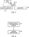
- Fig. 7 illustrates an example apparatus 1 in use in a roll to roll environment.
- a layer of two dimensional material 7 is formed on a growth substrate 71.
- the growth substrate 71 could comprise a copper substrate which has been used to grow graphene or any other suitable two dimensional material 7.
- the roll to roll process may be used to remove the two dimensional material from the growth substrate 71 and attach it to another substrate 75.
- the another substrate 75 could be a post processing substrate, a target substrate, a transfer substrate or any other suitable substrate.
- an apparatus 1 which may be as described above, is used to remove the two dimensional material 7 from the growth substrate 71 and attach it to the another substrate 75.
- deformation of the apparatus 1 may be controlled by locally cooling or heating regions of the apparatus 1 with air jets 77.
- the air jets 77 may comprise hot or cold air depending on the materials that are used in the apparatus 1 and the current temperatures of the apparatus 1.
- the air jets 77 will cause a local change in temperature of a part of the apparatus 1.
- the different coefficients of thermal expansion will cause local deformation of the apparatus 1.
- the air jet 77 is directed towards an edge portion of the apparatus 1. This may provide the advantage that only the edge portion of the apparatus 1 is curled. This may create a higher and more focused peeling force between the apparatus 1 and the growth substrate 71. This may make the two dimensional material 7 easier to remove from the growth substrate 71.
- the apparatus 1 may comprise a polyimide film.
- the polyimide film could be placed on top of the growth substrate 71.
- the growth substrate 71 and the polyimide film may then be heated to cure the polyimide.
- the air jet 77 may then be used to cool the top edge of the apparatus 1 which may then cause the apparatus 1 to deform and enable the two dimensional material 7 to be removed from the growth substrate 71. Once the two dimensional material 7 has been removed from the growth substrate 71 it can then be transferred to the other substrate 75.
- Fig. 8 illustrates a method.
- the method may be implemented using example apparatus 1 as described above.
- the method comprises, at block 81, providing a layer of two dimensional material 7 on a first layer 3 of an apparatus 1.
- the apparatus 1 comprises a first layer 3 having a first coefficient of thermal expansion and a second layer 5, coupled to the first layer 3, having a second coefficient of thermal expansion.
- the first coefficient of thermal expansion is different to the second coefficient of thermal expansion.
- the method may also comprise, at block 83, changing the temperature so that the difference in the coefficients of thermal expansion causes deformation of at least part of the apparatus 1 and the deformation enables transfer of the two dimensional material 7.
- Examples of the disclosure provide an improved apparatus for transferring two dimensional substrates.
- the apparatus 1 may enable the transfer to be carried out at low temperatures and without any wet processing which reduces the risk of damaging or contaminating the two dimensional material.
- the apparatus 1 may be designed to have particular temperatures at which they deform to enable transfer of the two dimensional material 7.
- the polymers that are used or the cross linking of the polymers may be selected so that the material deforms at a particular temperature. This may enable devices to be designed to operate at particular temperatures.
- the apparatus 1 may also be designed to deform in certain ways. In some examples the apparatus 1 can curl one way at a first temperature and another way at a second temperature. These different deformations may enable the apparatus 1 to be attached to and released from different substrates.
- example or “for example” or “may” in the text denotes, whether explicitly stated or not, that such features or functions are present in at least the described example, whether described as an example or not, and that they can be, but are not necessarily, present in some of or all other examples.
- example “for example” or “may” refers to a particular instance in a class of examples.
- a property of the instance can be a property of only that instance or a property of the class or a property of a subclass of the class that includes some but not all of the instances in the class. It is therefore implicitly disclosed that a features described with reference to one example but not with reference to another example, can where possible be used in that other example but does not necessarily have to be used in that other example.
Landscapes
- Thin Film Transistor (AREA)
Abstract
Description
- Examples of the disclosure relate to apparatus and methods for enabling transfer of two dimensional materials. In particular they relate to apparatus and methods for releasing two dimensional materials from a substrate.
- Two dimensional materials such as graphene, hexagonal boron nitride, molybdenum disulphide or other materials can be used in microelectronic devices such as thin film transistors, transducers, sensors or other applications.
- In order to fabricate such devices the two dimensional material may be grown on growth substrate and then transferred to a target substrate. An intermediate substrate may be used to transfer the two dimensional material from the growth substrate to the target substrate. As the two dimensional materials are very thin it can be very difficult to transfer the two dimensional material between different substrates without contaminating or doping or otherwise damaging the two dimensional material.
- It is therefore useful to provide improved apparatus and methods for transferring two dimensional materials between different substrates.
- According to various, but not necessarily all, examples of the disclosure there is provided an apparatus comprising: a first layer having a first coefficient of thermal expansion and configured to support a layer of two dimensional material; a second layer, coupled to the first layer, having a second coefficient of thermal expansion; wherein the first coefficient of thermal expansion is different to the second coefficient of thermal expansion such that a change in temperature causes deformation of at least part of the apparatus and the deformation enables transfer of the two dimensional material.
- In some examples the transfer of the two dimensional material may comprise removing the first layer and the layer of two dimensional material from the second layer.
- In some examples the transfer of the two dimensional material may comprise removing the layer of two dimensional material from the first layer.
- In some examples the deformation may comprise a progressive bending of one or more layers of the apparatus which enables one or more layers of the apparatus to be separated from other layers. The deformation may comprise a progressive bending of the first layer. The deformation may comprise a progressive bending of the second layer.
- In some examples increasing the temperature of the apparatus may cause the apparatus to bend in a first direction and decreasing the temperature causes the apparatus to bend in a second direction.
- In some examples increasing the temperature of the apparatus may cause the apparatus to bend in a first direction and further increasing the temperature causes the apparatus to bend in a second direction.
- In some examples the first layer and the second layer may have different glass transition temperatures.
- In some examples the change in temperature may be applied locally to a portion of the apparatus.
- In some examples the apparatus may comprise more than two layers.
- In some examples the apparatus may be used in roll to roll manufacturing.
- According to various, but not necessarily all, examples of the disclosure there is provided a method comprising: providing a layer of two dimensional material on a first layer of an apparatus, wherein the apparatus comprises a first layer having a first coefficient of thermal expansion and a second layer, coupled to the first layer, having a second coefficient of thermal expansion wherein the first coefficient of thermal expansion is different to the second coefficient of thermal expansion; and changing the temperature so that the difference in the coefficients of thermal expansion causes deformation of at least part of the apparatus and the deformation enables transfer of the two dimensional material.
- In some examples the transfer of the two dimensional material may comprise removing the first layer and the layer of two dimensional material from the second layer.
- In some examples the transfer of the two dimensional material may comprise removing the layer of two dimensional material from the first layer.
- In some examples the deformation may comprise a progressive bending of one or more layers of the apparatus which enables one or more layers of the apparatus to be separated from other layers. The deformation may comprise a progressive bending of the first layer. The deformation may comprise a progressive bending of the second layer.
- In some examples increasing the temperature of the apparatus may cause the apparatus to bend in a first direction and decreasing the temperature causes the apparatus to bend in a second direction.
- In some examples increasing the temperature of the apparatus may cause the apparatus to bend in a first direction and further increasing the temperature causes the apparatus to bend in a second direction.
- In some examples the first layer and the second layer may have different glass transition temperatures.
- In some examples the change in temperature may be applied locally to a portion of the apparatus.
- In some examples the apparatus may comprise more than two layers.
- In some examples the method may be used in roll to roll manufacturing.
- According to various, but not necessarily all, examples of the disclosure, there is provided examples as claimed in the appended claims.
- For a better understanding of various examples that are useful for understanding the detailed description, reference will now be made by way of example only to the accompanying drawings in which:
-
Fig. 1 illustrates an apparatus; -
Figs. 2A to 2F illustrate apparatus in use; -
Figs. 3A to 3C illustrate apparatus in use; -
Fig. 4 illustrates another apparatus; -
Figs. 5A to 5D illustrate an apparatus in use; -
Figs. 6A to 6E illustrate an example apparatus; -
Fig. 7 illustrates an example apparatus in use; and -
Fig. 8 illustrates an example method. - The figures illustrate an
apparatus 1 comprising: afirst layer 3 having a first coefficient of thermal expansion and configured to support a layer of twodimensional material 7; asecond layer 5, coupled to thefirst layer 3, having a second coefficient of thermal expansion; wherein the first coefficient of thermal expansion is different to the second coefficient of thermal expansion such that a change in temperature causes deformation of at least part of theapparatus 1 and the deformation enables transfer of the twodimensional material 7. - The
apparatus 1 may be for transferring a layer of two dimensional material from a first substrate to a second, different substrate. In some examples theapparatus 1 may be for releasing a two dimensional material from a growth substrate and/or transferring the two dimensional material to a target substrate. -
Fig. 1 schematically illustrates anapparatus 1 according to examples of the disclosure. Theapparatus 1 comprises afirst layer 3 and asecond layer 5. Thefirst layer 3 is configured to support a layer of twodimensional material 7. - In the example of
Fig. 1 thefirst layer 3 is provided overlaying thesecond layer 5 so that the first andsecond layers apparatus 1 could also be provided with thesecond layer 5 overlaying thefirst layer 3. - In the
example apparatus 1 ofFig. 1 the twodimensional material 7 is provided on a surface of thefirst layer 3. The twodimensional material 7 is provided on a first surface of thefirst layer 3 and thesecond layer 5 is coupled to the opposite surface of thefirst layer 3. - The layer of two
dimensional material 7 may comprise a very thin layer of material. In some examples the layer of twodimensional material 7 could be an atomic monolayer. In some examples the layer of twodimensional material 7 could comprise several atomic monolayers. The layer of two dimensional material could comprise graphene, molybdenum disulphide, boron nitride or any other suitable material. - The
first layer 3 and thesecond layer 5 are coupled together. In some examples the first andsecond layers - In some examples the
first layer 3 may be coupled to thesecond layer 5 so that deformation of one of thelayers other layer first layer 3 may be coupled to thesecond layer 5 such that deformation of one of thelayers second layers - In the example of
Fig. 1 thefirst layer 3 is coupled directly to thesecond layer 5. There are no intervening components between thefirst layer 3 and thesecond layer 5. In other examples one or more intervening components may be provided between thefirst layer 3 and thesecond layer 5. For instance, in some examples theapparatus 1 may comprise more than twolayers first layer 3 and thesecond layer 5. - The
first layer 3 has a first coefficient of thermal expansion and thesecond layer 5 has a second coefficient of thermal expansion. The materials that are used for thedifferent layers apparatus 1 is changed theapparatus 1, or at least part of the apparatus, is deformed. The deformation of theapparatus 1 may enable the two dimensional material to be transferred between substrates. -
Fig. 1 illustrates theapparatus 1 in an un-deformed state. In the un-deformed state each of the layers is flat or substantially flat. If the temperature of theapparatus 1, or at least part of theapparatus 1, is changed this will cause deformation of theapparatus 1. In some examples the change in temperature may cause all of theapparatus 1 to deform. In other examples the change in temperature may only cause part of theapparatus 1 to deform. - The
first layer 3 and thesecond layer 5 may comprise any suitable materials. The materials may be chosen so that the deformation of theapparatus 1 required to transfer the twodimensional material 7 occurs at a particular temperature. - In some examples the materials used for the
first layer 3 and thesecond layer 5 may be selected so that the two layers have a different glass transition temperature. As a material has a much smaller Young's modulus above the glass transition temperature this will cause a large reduction in the modulus for one of thelayers 3, but not for the other layer. The material will also increase the coefficient of thermal expansion above the glass transition temperature. This will increase the differences in coefficient of thermal expansions at given temperatures. This property of the materials may be used to control the deformation of theapparatus 1. - The materials that are used for the
respective layers apparatus 1 may be selected to have particular glass transition temperatures. The glass transition temperatures may enable the deformation of theapparatus 1 to be controlled so that the deformation occurs at specific temperatures and/or at specific locations within theapparatus 1. In some examples the materials used for thelayers layer apparatus 1 to be controlled by controlling the temperature. - In some examples the first and
second layers - In the
example apparatus 1 ofFig. 1 the twodimensional material 7 is provided on a surface of thefirst layer 3. The twodimensional material 7 is provided on a first surface of thefirst layer 3 and thesecond layer 5 is coupled to the opposite surface of thefirst layer 3. In some such examples theapparatus 1 may be arranged so that both thefirst layer 3 and thesecond layer 5 provide a deformable substrate which enables the twodimensional material 7 to be transferred. In other examples theapparatus 1 may be arranged so that deformation causes thefirst layer 3 to separate from thesecond layer 5 so that only thefirst layer 3 supports the two dimensional material as it is being transferred. - It is to be appreciated that in some examples the two dimensional material could be provided between the
first layer 3 and thesecond layer 5. In such examples the deformation of theapparatus 1 may enable thefirst layer 3 to separate from thesecond layer 5 which may enable the twodimensional material 7 to be transferred from thefirst layer 3 to thesecond layer 5. -
Figs. 2A to 2F illustrate twoexample apparatus 1 in use.Figs. 2A to 2C illustrate afirst example apparatus 1 attached to asubstrate 21.Figs. 2D to 2F illustrate asecond example apparatus 1 attached to asubstrate 21. - The
substrate 21 could be a growth substrate. Thegrowth substrate 21 may comprise any material upon which a layer of twodimensional material 7 can be fabricated. In some examples thegrowth substrate 21 could comprise a layer of copper. In such cases theapparatus 1 may be used to remove a layer of twodimensional material 7 from thesubstrate 21. - In other examples the
substrate 21 could be a target substrate. The target substrate could comprise a layer which is configured to receive the twodimensional material 7. The target substrate could form part of a microelectronic device. The target substrate could comprise silicon or any other suitable material. In such examples theapparatus 1 may be used to transfer the twodimensional material 7 to thesubstrate 21. - In the example of
Figs. 2A to 2C theapparatus 1 is arranged with thefirst layer 3 positioned underneath thesecond layer 5. Thefirst layer 3 is provided adjacent to thesubstrate 21 and thesecond layer 5 is provided overlaying thefirst layer 3. In the example ofFigs. 2A to 2C thesecond layer 5 has a smaller coefficient of thermal expansion than thefirst layer 3. That is, thefirst layer 3, which is adjacent to thesubstrate 21, has the higher coefficient of thermal expansion. -
Fig. 2A illustrates theapparatus 1 and thesubstrate 21 in an un-deformed state. In the un-deformed state each of thelayers apparatus 1 is flat or substantially flat. - The
apparatus 1 may be deformed by changing the temperature of theapparatus 1. In the example ofFig. 2A theapparatus 1 is heated. The heating of theapparatus 1 causes an expansion of thefirst layer 3 and thesecond layer 5 as indicated by thearrows -
Fig. 2B shows theapparatus 1 after the temperature has increased. As thefirst layer 3 has the higher coefficient of thermal expansion than thesecond layer 5 thefirst layer 3 expands more than thesecond layer 5. Thesubstrate 21 has not expanded significantly. This generates stress at the interface between thefirst layer 3 and thesubstrate 21. - To reduce the stress in the system the
apparatus 1 deforms.Fig. 2C shows theapparatus 1 in a deformed state. In the example ofFigs. 2A to 2C theapparatus 1 deforms by curling. The curling comprises a progressive bending of both the first andsecond layers apparatus 1. In the example ofFig. 2C theapparatus 1 bends away from thesubstrate 21 which enables theapparatus 1 to be gradually removed from the surface of thesubstrate 21. -
Figs. 2D to 2F show anotherexample apparatus 1. In the examples ofFigs 2D to 2F theapparatus 1 is also attached to asubstrate 21 however inFigs. 2D to 2F thesecond layer 5 has the higher coefficient of thermal expansion. That is, thefirst layer 3, which is adjacent to thesubstrate 21 has the lower coefficient of thermal expansion. -
Fig. 2D illustrates theapparatus 1 and thesubstrate 21 in an un-deformed state. As in the previous examples, in the un-deformed state each of thelayers apparatus 1 is flat or substantially flat. - The
apparatus 1 may be deformed by changing the temperature of theapparatus 1. In the example ofFig. 2D theapparatus 1 is cooled. The cooling of the apparatus1 causes contraction of thefirst layer 3 and thesecond layer 5 as indicated by thearrows -
Fig. 2E shows theapparatus 1 after it has been cooled. As thesecond layer 5 has the higher coefficient of thermal expansion thesecond layer 5 contracts more than thefirst layer 3. This generates stress at the interface between thefirst layer 3 and thesecond layer 5 which causes theapparatus 1 to deform. The stress generated between thefirst layer 3 and thesubstrate 21 in the example ofFig. 2E may be lower that the stress generated between thefirst layer 3 and thesubstrate 21 in the example ofFig. 2B . -
Fig. 2F shows theapparatus 1 in a deformed state. In the example ofFig. 2F theapparatus 1 also deforms by curling. The curling comprises a progressive bending of both the first andsecond layers apparatus 1. In the example ofFig. 2F theapparatus 1 bends away from thesubstrate 21 which enables theapparatus 1 to be gradually removed from the surface of thesubstrate 21. - In the example of
Figs. 2A to 2F both thefirst layer 3 and thesecond layer 5 are deformed. In other examples only one of the layers might be deformed. Also in the examples ofFigs. 2A to 2F all of theapparatus 1 is deformed. In other examples only a part of theapparatus 1 might be deformed. For instance a temperature change might be applied locally to enable part of anapparatus 1 to be deformed. - The radius of curvature of the
apparatus 1 when it is deformed is determined by the difference in coefficients of the thermal expansion of therespective layers apparatus 1 is changed different strains are induced in thedifferent layers apparatus 1. The differences in the strains cause theapparatus 1 to deform so that the stresses within theapparatus 1 are balanced. - The strain produced in the
layers apparatus 1 is given byequation 1, where α is the coefficient of thermal expansion and ΔT is the change in temperature.
- Where the
layers equation 2 where E is the Young's modulus of the material.
- The radius of curvature of a
bilayer apparatus 1 is given byequation 3 where E' is the lateral Youngs modulus, w and t are the width and thickness of the two materials respectively and r is the radius of curvature.
- It is to be appreciated that
equation 3 covers a simple case and assumes that the Young's modulus remains constant, that theapparatus 1 is free standing and the layers of theapparatus 1 are uniformly heated. However it can be seen from this equation that the curvature of theapparatus 1 is proportional to the difference in thermal coefficients of two adjacent layers. - If the
apparatus 1 is heated to or above the glass transition temperature of one of thelayers layer apparatus 1. - In examples of the disclosure the deformation of the
apparatus 1 may be controlled by locally cooling or heating regions of theapparatus 1 with thin strips of jetted hot or cold air. The strips of air will cause a local change in temperature of a part of theapparatus 1. The different coefficients of thermal expansion will cause local deformation of theapparatus 1. -
Figs. 3A to 3C illustrate anotherexample apparatus 1 in use. The example ofFigs. 3A to 3C differs from the example ofFigs. 2A to 2F in that in the previous examples both layers of theapparatus 1 were deformed whereas in the example ofFigs. 3A to 3C only one of the layers is deformed. - In
Fig. 3A asecond layer 5 of theapparatus 1 is formed. In the example ofFig. 3A thesecond layer 5 comprises asupport substrate 31. Thesupport substrate 31 may provide a rigid or substantially rigid substrate which may provide support while the twodimensional material 7 is being fabricated and/or patterned. Thesupport substrate 31 may comprise a silicon wafer or any other suitable material. - The
support substrate 31 may be flat or substantially flat. - In
Fig. 3B thefirst layer 3 of theapparatus 1 is provided overlaying thesecond layer 5. Thefirst layer 3 may be coupled to thesecond layer 5 by Van der Waals bonds or any other suitable means. In theexample apparatus 1 ofFig. 3B there are no intervening layers between thefirst layer 3 and thesecond layer 5. - In this example the layer of two
dimensional material 7 may be fabricated and/or patterned on thefirst layer 3. The twodimensional material 7 may be fabricated and/or patterned on thesurface 33 of thefirst layer 3. The twodimensional material 7 may be formed as microelectronic devices or components of microelectronic devices. For instance the twodimensional material 7 could be formed to provide source and drain electrodes and a channel for thin film transistors (TFTs) or any other suitable components of microelectronic devices. - The two
dimensional material 7 may be formed using nano-imprint or photolithography techniques or any other suitable method. - The
first layer 3 may comprise a material which has a higher thermal coefficient of expansion than thesecond layer 5. In some examples the thermal coefficient of expansion of thefirst layer 3 may be much great than the thermal coefficient of expansion of thesecond layer 5. In the examples ofFig. 3B thefirst layer 3 may be formed from a polymer material such as PEN. It is to be appreciated that other materials may be used in other examples. - In
Fig. 3C theapparatus 1 has been heated and is in a deformed state. The heating of theapparatus 1 causes thefirst layer 3 to expand more than thesecond layer 5. In the examples ofFig. 3C the expansion of thefirst layer 3 is much greater than any expansion of thesecond layer 5. The expansion causes stress at the interface between the first andsecond layers first layer 3 of theapparatus 1 to deform while thesecond layer 5 remains flat or substantially flat. - The deformation of the
apparatus 1 comprises the progressive bending of thefirst layer 3. In the deformed state ofFig. 3C thefirst layer 3 has curled away from thesupport substrate 31 provided bysecond layer 5 while thesecond layer 5 has remained substantially flat. This curling may enable thefirst layer 3, and the layer of twodimensional material 7 which is supported by thefirst layer 3, to be removed from thesupport substrate 31 provided by thesecond layer 5. This may enable the twodimensional material 7 which has been fabricated on thefirst layer 3 to be transferred to another substrate or device. Therefore theexample apparatus 1 ofFigs. 3A to 3C enables the transfer of a twodimensional material 7 by removing thefirst layer 3 and the layer of twodimensional material 7 from thesecond layer 5. - The
apparatus 1 may be heated to the glass transition temperature of thefirst layer 3. Above the glass transition temperature the Young's modulus will reduce significantly and the thermal coefficient of expansion of thefirst layer 3 will increase significantly. This will increase the difference in the thermal coefficient of expansion between the twolayers first layer 3 the glass transition temperature could be around 150°C. - In examples of the disclosure such as the examples of
Figs. 3A to 3C the twodimensional material 7 can be removed from the wafer by heating theapparatus 1. There is no need for any wet processing of theapparatus 1. This may reduce the likelihood of doping and/or contamination of the twodimensional material 7. - Also the
apparatus 1 does not need to be heated to a very high temperature. For examples where PEN is used as the material for thefirst layer 3 the apparatus could be heated to a temperature of 150°C. This may be above the glass transition temperature of a material such as PEN and so may be sufficient to cause the deformation of thefirst layer 3 of theapparatus 1. This temperature may still be low enough to avoid damaging the twodimensional material 7. -
Fig. 4 illustrates anotherexample apparatus 1. In this example theapparatus 1 is provided between asupport substrate 41 and atarget substrate 43. Theexample apparatus 1 ofFig. 4 may be arranged to deform in different directions so as to enable theapparatus 1 to be attached to and released from different substrates. - The
example apparatus 1 ofFig. 4 comprises afirst layer 3 and asecond layer 5. In the example ofFig. 4 thefirst layer 3 may comprise a flexible polymer such as PET, PEN or any other suitable material. Thesecond layer 5 may comprise a material such as PDMS. The first andsecond layers first layer 3 may be coupled to thesecond layer 5 by Van der Waals interactions or any other suitable means. - The
second layer 5 of theapparatus 1 is coupled to thesupport substrate 41. Thesupport substrate 41 may provide a rigid support layer while the twodimensional material 7 is being formed. The twodimensional material 7 may be formed on the surface of thefirst layer 3. Thefirst layer 3 may then be coupled to thetarget substrate 43 to enable the twodimensional material 7 to be transferred from thefirst layer 3 to thetarget substrate 43. - The temperature of the
apparatus 1 may be changed in order to enable theapparatus 1 to be removed from thesupport substrate 41 and thetarget layer 43. A first change in temperature may be used to cause a deformation which enables thesecond layer 5 to be released from thesupport substrate 41 and a second change in temperature may be used to cause a deformation which enables thefirst layer 3 to be released from thetarget substrate 43. - For instance, in some examples the
apparatus 1 may be deformed in a first direction by decreasing the temperature. This will cause thelayer apparatus 1 to bend in a first direction. Theapparatus 1 could then be deformed in a second direction by increasing the temperature. The heating would cause the layer with the largest coefficient of thermal expansion to expand more and may cause theapparatus 1 to bend in a second direction. The second direction could be opposite to the first direction. Therefore by following a heating pattern theapparatus 1 could be removed from both thesupport substrate 41 and thetarget substrate 43. - In the particular example of
Fig. 4 theapparatus 1 could be heated to enable it to be removed from thesupport substrate 41. It might then be cooled to enable it to be removed from thetarget substrate 43. It is to be appreciated that other heating patterns could be used in other examples of the disclosure. -
Figs. 5A to 5D illustrate anotherexample apparatus 1 in use. In the example ofFigs. 5A to 5D theapparatus 1 enables transfer of a twodimensional material 7 by enabling the layer of twodimensional material 7 to be removed from agrowth substrate 51 and then removed from thefirst layer 3 to atarget substrate 53. - In
Fig. 5A a layer of twodimensional material 7 is grown on thegrowth substrate 51. Thegrowth substrate 51 may comprise any material upon which a layer of twodimensional material 7 can be fabricated. In some examples thegrowth substrate 51 could comprise a layer of copper or any other suitable material. The layer of twodimensional material 7 could comprise graphene or any other suitable twodimensional material 7. - In
Fig. 5B anapparatus 1 is provided overlaying the twodimensional material 7. Theapparatus 1 comprises afirst layer 3 and asecond layer 5. Theapparatus 1 is arranged so that thefirst layer 3 attaches to the twodimensional layer 7. - In the example of
Fig. 5 theapparatus 1 is heated before it is positioned overlaying the twodimensional material 7. The heating of theapparatus 1 causes theapparatus 1 to curl as shown inFig. 5B . Theheated apparatus 1 may then be positioned adjacent the twodimensional material 7. When theapparatus 1 is initially positioned adjacent the two dimensional material only afirst portion 55 of thefirst layer 3 is in contact with the twodimensional material 7. The rest of thefirst layer 3 is curled upwards so that agap 57 is provided between thefirst layer 3 and the twodimensional material 7. - As the
apparatus 1 cools it gradually uncurls so that thearea 55 of thefirst layer 3 which is in contact with the twodimensional material 7 gradually increases. As the material uncurls any air bubbles or other pockets of gas between theapparatus 1 and the twodimensional material 7 will be pushed out. This provides for improved lamination of theapparatus 1 and the twodimensional material 7. In some examples this may allow for theapparatus 1 to self laminate with the twodimensional material 7 and thegrowth substrate 51. - In order to ensure good adhesion to the two
dimensional material 7 theapparatus 1 may be heated above the glass transition temperature of thefirst layer 3. This may also allow for uniform contact across the surface of the twodimensional material 7. - Once the
apparatus 1 has been attached to the twodimensional material 7 thegrowth substrate 51 may be removed.Fig. 5C illustrates theapparatus 1 after thegrowth substrate 51 has been removed. Thegrowth substrate 51 may be removed using any suitable method. For instance where thegrowth substrate 51 comprises copper the growth substrate may be removed by wet etching, electrochemical oxidation or other suitable techniques. - In the example of
Fig. 5C theapparatus 1 is flat or substantially flat. Theapparatus 1 may be arranged in the flat configuration before thegrowth substrate 51 is removed. - Once the
growth substrate 51 has been removed the twodimensional material 7 is left attached to thefirst layer 3 of theapparatus 1. The twodimensional material 7 can then be attached to atarget substrate 53. -
Fig. 5D illustrates theapparatus 1 being removed from thetarget substrate 53. Theapparatus 1 is heated to cause thefirst layer 3 to bend away from the twodimensional material 7. The enables the controlled release of thefirst layer 3 from the twodimensional material 7 so that theapparatus 1 may be removed from the layer of twodimensional material 7 leaving the twodimensional material 7 on thetarget substrate 53. - In this example the
apparatus 1 acts as a transfer substrate and enables a layer of twodimensional material 7 to be removed from afirst substrate 51 and attached to anothersubstrate 53. - In the example of
Figs. 5A to 5B thefirst layer 3 of theapparatus 1 may have the higher coefficient of thermal expansion so that thefirst layer 3 of theapparatus 1 curls away from the twodimensional material 7 when it is heated but curls towards the twodimensional material 7 when it is cooled. -
Figs. 6A to 6E illustrate anexample apparatus 1 in which theapparatus 1 comprises more than two layers. In the example ofFigs. 6A to 6E theapparatus 1 comprises three layers. It is to be appreciated that any other number of layers could be used in other examples of the disclosure. - In this example the
apparatus 1 comprises afirst layer 3, asecond layer 5, and athird layer 61. Thefirst layer 3 may be arranged to support a layer of twodimensional material 7. The layer of twodimensional material 7 is not shown inFigs. 6A to 6E. Fig. 6A illustrates theapparatus 1 in an un-deformed state. In the un-deformed state each of thelayers apparatus 1 is flat or substantially flat. - The
first layer 3 is provided over laying thesecond layer 5 and thesecond layer 5 is provided overlaying thethird layer 61 so that the threelayers apparatus 1 could be provided in a different order. - In the
example apparatus 1 ofFig. 6 the twodimensional material 7 is provided on a surface of thefirst layer 3. The twodimensional material 7 is provided on a first surface of thefirst layer 3 and thesecond layer 5 is coupled to the opposite surface of thefirst layer 3. Thefirst layer 3 is coupled to a first surface of thesecond layer 5 and thethird layer 61 is coupled to the opposite surface of thesecond layer 5. - The
layers apparatus 1 are coupled together. Thelayers - In some examples the
layers layers other layers - The
layers layers Figs. 6A to 6E thethird layer 61 has the largest coefficient of thermal expansion. Thethird layer 61 may have a much larger coefficient of thermal expansion than the first andsecond layers - In some examples the
layers first layer 3 has glass transition temperature T g1, thesecond layer 5 has glass transition temperature T g2 and thethird layer 61 has glass transition temperature T g3. - In the particular example of
Figs. 6A to 6E thethird layer 61 has the lowest glass transition temperature such that:
- The
third layer 61 may undergo a large reduction in Young's modulus when theapparatus 1 is heated aboveT g3 compared to the first andsecond layers -
Fig. 6B illustrates theapparatus 1 being heated below T g3. - The force F in each layer is given by equation 4. Where A is the cross sectional area of the apparatus 1

- In
Fig. 6B the force F1 in thefirst layer 3 is indicated by thearrows 63, the force F2 in thesecond layer 5 is indicated by thearrows 65 and the force F3 in thethird layer 61 is indicated by thearrows 67. - In the example of
Figs. 6A to 6E the materials of the layers are chosen to have thermal coefficients of expansion, Young's modulus and glass transition temperatures such that below T g3 the force F3 in thethird layer 61 is much greater than the force F1 in thefirst layer 3 and the force F1 in thefirst layer 3 is greater than the force F2 in thesecond layer 5.
- These forces cause the
apparatus 1 to bend by curling upwards as illustrated inFig. 6C . -
Fig. 6D illustrates theapparatus 1 being heated above T g3. Once the temperature rises above T g3 then the Young's modulus of thethird layer 61 is greatly reduced. At temperatures above T g3 thethird layer 61 becomes soft and viscoelastic so will begin to flow. This also greatly reduces the thermal expansion force F3, for a given time period, in the third layer. - At temperatures above T g3 the force F1 in the
first layer 3 is much greater than the force F3 in thethird layer 61 and the force F3 in thethird layer 61 is greater than the force F2 in thesecond layer 5.
- These forces cause the
apparatus 1 to bend by curling downwards as illustrated inFig. 6E . - Therefore the
example apparatus 1 ofFigs. 6A to 6E can be deformed in different directions by heating theapparatus 1 above the glass transition temperatures of one or more of therespective layers - Examples of materials which could be used to form the
layers apparatus 1 are given in the following tableLayer Material Tg(°C) CTE (ppm/°C Modulus T < 62 (E, Pa) Modulus T>62 (E, GPa) Change in force per unit area ∼E*CTE First layer PI- 2525 325 50 2.5 2.5 125 Second layer PI - 2610 360 3 8.5 8.5 25.5 Third layer PA 62 205 0.73 0.2 150,41 - In these examples the first and
second layers third layer 61 may comprise polyamide (PA). The polyamide has a lower modulus than the polyimide. In other examples materials with a lower modulus such as polyacrylamide or polycarbonate could be used for thethird layer 61. - The table shows the Young's modulus of the example materials at temperatures above and below the glass transition temperature of the
third layer 61. The reduction in the Young's modulus of the third layer reduces the change in force per unit area from 150 to 41. - In other examples the same effect can be achieved using only two
layers second layer 5 could have a large coefficient of thermal expansion and a low glass transition temperature. In such examples thesecond layer 5 would undergo a large reduction in Young's modulus once the temperature is raised above the glass transition temperature. Thefirst layer 3 would have a lower coefficient of thermal expansion but a higher glass transition temperature. - Examples of materials which could be used to form the
layers bilayer apparatus 1 are given in the following tableLayer Material Tg(°C) CTE (ppm/°C.) Modulus T < 150 (E, Pa) Modulus T>150 (E, GPa) Change in force per unit area ∼E*CTE First layer Ph1 (50% X-linked) 150 200 2 1.2 400,240 Second layer Ph2 (90% X-linked) 175 100 3.4 3.2 340,320 - In this bilayer example the reduction in forces is achieved by controlling the amount of cross-linking in a polymer layer to control the glass transition temperature. In this example the
first layer 3 is a phenolic resin (Ph1) with 50% cross linking and thesecond layer 5 is a phenolic resin (Ph2) with 90% cross linking. Other materials and other amounts of cross linking may be used in other examples of the disclosure. - Increasing the amounts of cross-linking within the polymer results in a higher glass transition temperature and a reduced coefficient of thermal expansion. The Young's modulus also tends to increase with the amount of cross-linking within the polymer. The Young's' modulus will also have a smaller reduction at temperatures above the glass transition temperature due to increased crystallinity within the polymer.
- It is to be appreciated that other materials and numbers of layers may be used in other examples of the disclosure.
-
Fig. 7 illustrates anexample apparatus 1 in use in a roll to roll environment. - In the example of
Fig. 7 a layer of twodimensional material 7 is formed on agrowth substrate 71. For instance thegrowth substrate 71 could comprise a copper substrate which has been used to grow graphene or any other suitable twodimensional material 7. - The roll to roll process may be used to remove the two dimensional material from the
growth substrate 71 and attach it to anothersubstrate 75. The anothersubstrate 75 could be a post processing substrate, a target substrate, a transfer substrate or any other suitable substrate. - In the examples of
Fig. 7 anapparatus 1, which may be as described above, is used to remove the twodimensional material 7 from thegrowth substrate 71 and attach it to the anothersubstrate 75. - In this example deformation of the
apparatus 1 may be controlled by locally cooling or heating regions of theapparatus 1 withair jets 77. Theair jets 77 may comprise hot or cold air depending on the materials that are used in theapparatus 1 and the current temperatures of theapparatus 1. - The
air jets 77 will cause a local change in temperature of a part of theapparatus 1. The different coefficients of thermal expansion will cause local deformation of theapparatus 1. - In the example of
Fig. 7 theair jet 77 is directed towards an edge portion of theapparatus 1. This may provide the advantage that only the edge portion of theapparatus 1 is curled. This may create a higher and more focused peeling force between theapparatus 1 and thegrowth substrate 71. This may make the twodimensional material 7 easier to remove from thegrowth substrate 71. - In some examples the
apparatus 1 may comprise a polyimide film. The polyimide film could be placed on top of thegrowth substrate 71. Thegrowth substrate 71 and the polyimide film may then be heated to cure the polyimide. Theair jet 77 may then be used to cool the top edge of theapparatus 1 which may then cause theapparatus 1 to deform and enable the twodimensional material 7 to be removed from thegrowth substrate 71. Once the twodimensional material 7 has been removed from thegrowth substrate 71 it can then be transferred to theother substrate 75. -
Fig. 8 illustrates a method. The method may be implemented usingexample apparatus 1 as described above. The method comprises, atblock 81, providing a layer of twodimensional material 7 on afirst layer 3 of anapparatus 1. Theapparatus 1 comprises afirst layer 3 having a first coefficient of thermal expansion and asecond layer 5, coupled to thefirst layer 3, having a second coefficient of thermal expansion. The first coefficient of thermal expansion is different to the second coefficient of thermal expansion. The method may also comprise, atblock 83, changing the temperature so that the difference in the coefficients of thermal expansion causes deformation of at least part of theapparatus 1 and the deformation enables transfer of the twodimensional material 7. - Examples of the disclosure provide an improved apparatus for transferring two dimensional substrates. The
apparatus 1 may enable the transfer to be carried out at low temperatures and without any wet processing which reduces the risk of damaging or contaminating the two dimensional material. - The
apparatus 1 may be designed to have particular temperatures at which they deform to enable transfer of the twodimensional material 7. For instance the polymers that are used or the cross linking of the polymers may be selected so that the material deforms at a particular temperature. This may enable devices to be designed to operate at particular temperatures. - The
apparatus 1 may also be designed to deform in certain ways. In some examples theapparatus 1 can curl one way at a first temperature and another way at a second temperature. These different deformations may enable theapparatus 1 to be attached to and released from different substrates. - The term "comprise" is used in this document with an inclusive not an exclusive meaning. That is any reference to X comprising Y indicates that X may comprise only one Y or may comprise more than one Y. If it is intended to use "comprise" with an exclusive meaning then it will be made clear in the context by referring to "comprising only one..." or by using "consisting".
- In this detailed description, reference has been made to various examples. The description of features or functions in relation to an example indicates that those features or functions are present in that example. The use of the term "example" or "for example" or "may" in the text denotes, whether explicitly stated or not, that such features or functions are present in at least the described example, whether described as an example or not, and that they can be, but are not necessarily, present in some of or all other examples. Thus "example", "for example" or "may" refers to a particular instance in a class of examples. A property of the instance can be a property of only that instance or a property of the class or a property of a subclass of the class that includes some but not all of the instances in the class. It is therefore implicitly disclosed that a features described with reference to one example but not with reference to another example, can where possible be used in that other example but does not necessarily have to be used in that other example.
- Although embodiments of the present invention have been described in the preceding paragraphs with reference to various examples, it should be appreciated that modifications to the examples given can be made without departing from the scope of the invention as claimed.
- Features described in the preceding description may be used in combinations other than the combinations explicitly described.
- Although functions have been described with reference to certain features, those functions may be performable by other features whether described or not.
- Although features have been described with reference to certain embodiments, those features may also be present in other embodiments whether described or not.
- Whilst endeavoring in the foregoing specification to draw attention to those features of the invention believed to be of particular importance it should be understood that the Applicant claims protection in respect of any patentable feature or combination of features hereinbefore referred to and/or shown in the drawings whether or not particular emphasis has been placed thereon.
Claims (15)
- An apparatus comprising:a first layer having a first coefficient of thermal expansion and configured to support a layer of two dimensional material;a second layer, coupled to the first layer, having a second coefficient of thermal expansion;wherein the first coefficient of thermal expansion is different to the second coefficient of thermal expansion such that a change in temperature causes deformation of at least part of the apparatus and the deformation enables transfer of the two dimensional material.
- An apparatus as claimed in any preceding claim wherein the transfer of the two dimensional material comprises removing the first layer and the layer of two dimensional material from the second layer.
- An apparatus as claimed in claim 1 wherein the transfer of the two dimensional material comprises removing the layer of two dimensional material from the first layer.
- An apparatus as claimed in any preceding claim wherein the deformation comprises a progressive bending of one or more layers of the apparatus which enables one or more layers of the apparatus to be separated from other layers.
- An apparatus as claimed in claim 4 wherein the deformation comprises a progressive bending of the first layer.
- An apparatus as claimed in any of claims 4 to 5 wherein the deformation comprises a progressive bending of the second layer.
- An apparatus as claimed in any preceding claim wherein increasing the temperature of the apparatus causes the apparatus to bend in a first direction and decreasing the temperature causes the apparatus to bend in a second direction.
- An apparatus as claimed in any preceding claim wherein increasing the temperature of the apparatus causes the apparatus to bend in a first direction and further increasing the temperature causes the apparatus to bend in a second direction.
- An apparatus as claimed in any preceding claim wherein the first layer and the second layer have different glass transition temperatures.
- An apparatus as claimed in any preceding claim wherein the change in temperature is applied locally to a portion of the apparatus.
- An apparatus as claimed in any preceding claim wherein the apparatus comprises more than two layers.
- An apparatus as claimed in any preceding claim wherein the apparatus is used in roll to roll manufacturing.
- A method comprising:providing a layer of two dimensional material on a first layer of an apparatus, wherein the apparatus comprises a first layer having a first coefficient of thermal expansion and a second layer, coupled to the first layer, having a second coefficient of thermal expansion wherein the first coefficient of thermal expansion is different to the second coefficient of thermal expansion; andchanging the temperature so that the difference in the coefficients of thermal expansion causes deformation of at least part of the apparatus and the deformation enables transfer of the two dimensional material.
- A method as claimed in claim 13 wherein the transfer of the two dimensional material comprises removing the first layer and the layer of two dimensional material from the second layer.
- A method as claimed in claim 13 wherein the transfer of the two dimensional material comprises removing the layer of two dimensional material from the first layer.
Priority Applications (2)
| Application Number | Priority Date | Filing Date | Title |
|---|---|---|---|
| EP15176522.9A EP3118893A1 (en) | 2015-07-13 | 2015-07-13 | An apparatus and method for enabling transfer of two dimensional materials |
| PCT/FI2016/050465 WO2017009526A1 (en) | 2015-07-13 | 2016-06-28 | An apparatus and method for enabling transfer of two dimensional materials |
Applications Claiming Priority (1)
| Application Number | Priority Date | Filing Date | Title |
|---|---|---|---|
| EP15176522.9A EP3118893A1 (en) | 2015-07-13 | 2015-07-13 | An apparatus and method for enabling transfer of two dimensional materials |
Publications (1)
| Publication Number | Publication Date |
|---|---|
| EP3118893A1 true EP3118893A1 (en) | 2017-01-18 |
Family
ID=53719639
Family Applications (1)
| Application Number | Title | Priority Date | Filing Date |
|---|---|---|---|
| EP15176522.9A Withdrawn EP3118893A1 (en) | 2015-07-13 | 2015-07-13 | An apparatus and method for enabling transfer of two dimensional materials |
Country Status (2)
| Country | Link |
|---|---|
| EP (1) | EP3118893A1 (en) |
| WO (1) | WO2017009526A1 (en) |
Cited By (1)
| Publication number | Priority date | Publication date | Assignee | Title |
|---|---|---|---|---|
| CN117446797A (en) * | 2023-10-20 | 2024-01-26 | 南京大学 | A transfer method for preparing two-dimensional homo/heterogeneous structures with clean interfaces |
Families Citing this family (3)
| Publication number | Priority date | Publication date | Assignee | Title |
|---|---|---|---|---|
| CN111887780A (en) * | 2019-05-05 | 2020-11-06 | 青岛海尔洗碗机有限公司 | Dish washer sprays arm structure and has dish washer of this spray arm structure |
| CN113337807A (en) * | 2021-05-12 | 2021-09-03 | 中国科学院物理研究所 | Method for preparing two-dimensional material |
| CN115527917A (en) * | 2022-10-10 | 2022-12-27 | 上海天马微电子有限公司 | Transfer stamp and transfer device |
Citations (3)
| Publication number | Priority date | Publication date | Assignee | Title |
|---|---|---|---|---|
| US20030224621A1 (en) * | 2002-05-31 | 2003-12-04 | Nokia Corporation | Method and apparatus for manufacturing organic semiconductor systems |
| US6682990B1 (en) * | 1999-09-09 | 2004-01-27 | Canon Kabushiki Kaisha | Separation method of semiconductor layer and production method of solar cell |
| WO2014181855A1 (en) * | 2013-05-10 | 2014-11-13 | 日本電気硝子株式会社 | Glass film manufacturing method and electronic device manufacturing method |
-
2015
- 2015-07-13 EP EP15176522.9A patent/EP3118893A1/en not_active Withdrawn
-
2016
- 2016-06-28 WO PCT/FI2016/050465 patent/WO2017009526A1/en not_active Ceased
Patent Citations (3)
| Publication number | Priority date | Publication date | Assignee | Title |
|---|---|---|---|---|
| US6682990B1 (en) * | 1999-09-09 | 2004-01-27 | Canon Kabushiki Kaisha | Separation method of semiconductor layer and production method of solar cell |
| US20030224621A1 (en) * | 2002-05-31 | 2003-12-04 | Nokia Corporation | Method and apparatus for manufacturing organic semiconductor systems |
| WO2014181855A1 (en) * | 2013-05-10 | 2014-11-13 | 日本電気硝子株式会社 | Glass film manufacturing method and electronic device manufacturing method |
Cited By (1)
| Publication number | Priority date | Publication date | Assignee | Title |
|---|---|---|---|---|
| CN117446797A (en) * | 2023-10-20 | 2024-01-26 | 南京大学 | A transfer method for preparing two-dimensional homo/heterogeneous structures with clean interfaces |
Also Published As
| Publication number | Publication date |
|---|---|
| WO2017009526A1 (en) | 2017-01-19 |
Similar Documents
| Publication | Publication Date | Title |
|---|---|---|
| TWI477464B (en) | Glass - Resin composite manufacturing method | |
| WO2017009526A1 (en) | An apparatus and method for enabling transfer of two dimensional materials | |
| JP5065880B2 (en) | Fine structure transfer apparatus and fine structure transfer method | |
| Mondal et al. | Estimation of solid–liquid interfacial tension using curved surface of a soft solid | |
| JP2016018198A (en) | Display device | |
| TW201106447A (en) | Substrate structures applied in flexible electrical devices and fabrication method thereof | |
| US20100052216A1 (en) | Nano imprint lithography using an elastic roller | |
| KR101971470B1 (en) | Carrier film for transferring micro-device | |
| US20150316803A1 (en) | Curved surface display apparatus and method for producing the same | |
| KR102209564B1 (en) | Patterned stamp manufacturing method, patterned stamp imprinting method and imprinted article | |
| WO2005063464A3 (en) | Process of microstructuring of a surface of a multi-layered flexible substrate, and microstructured substrate | |
| TW201429710A (en) | Glass laminate, method for producing same, and supporting base with silicone resin layer | |
| KR102093340B1 (en) | Stamp structure for transfer printing and method of manufacturing the same, and transfer printing method using the stamp structure | |
| KR20120052648A (en) | Apparatus for transferring graphene and method for transferring graphene | |
| JP7637816B2 (en) | Method and apparatus for removing stamp | |
| KR20150085352A (en) | Lower protect film for display panel and display device comprising the same | |
| TWI661017B (en) | Resin temporarily, resin layer temporarily, rigid substrate with temporary resin layer, film substrate laminate, and film substrate processing process | |
| KR20190063454A (en) | Carrier film for transferring micro-device | |
| US20140048201A1 (en) | Bonding of thin lamina | |
| JP2015193101A (en) | Polymer film laminate and method for producing flexible electronic device using the same | |
| US20150236286A1 (en) | Electronic device package and manufacturing method thereof | |
| KR100998087B1 (en) | Active detachable chuck | |
| Yu et al. | Thermoresponsiveness of Integrated Ultra‐Thin Silicon with Poly (N‐isopropylacrylamide) Hydrogels | |
| JP5679211B2 (en) | Transfer sheet for transfer printing and manufacturing method thereof | |
| CN112526660B (en) | Method for manufacturing nano-grating on curved surface, optical device and electronic equipment |
Legal Events
| Date | Code | Title | Description |
|---|---|---|---|
| PUAI | Public reference made under article 153(3) epc to a published international application that has entered the european phase |
Free format text: ORIGINAL CODE: 0009012 |
|
| AK | Designated contracting states |
Kind code of ref document: A1 Designated state(s): AL AT BE BG CH CY CZ DE DK EE ES FI FR GB GR HR HU IE IS IT LI LT LU LV MC MK MT NL NO PL PT RO RS SE SI SK SM TR |
|
| AX | Request for extension of the european patent |
Extension state: BA ME |
|
| 17P | Request for examination filed |
Effective date: 20170717 |
|
| RBV | Designated contracting states (corrected) |
Designated state(s): AL AT BE BG CH CY CZ DE DK EE ES FI FR GB GR HR HU IE IS IT LI LT LU LV MC MK MT NL NO PL PT RO RS SE SI SK SM TR |
|
| RAP1 | Party data changed (applicant data changed or rights of an application transferred) |
Owner name: PROVENANCE ASSET GROUP LLC |
|
| STAA | Information on the status of an ep patent application or granted ep patent |
Free format text: STATUS: THE APPLICATION IS DEEMED TO BE WITHDRAWN |
|
| 18D | Application deemed to be withdrawn |
Effective date: 20200201 |