EP3118847A1 - Image displaying method, image displaying device, computer program and recording medium - Google Patents
Image displaying method, image displaying device, computer program and recording medium Download PDFInfo
- Publication number
- EP3118847A1 EP3118847A1 EP16163299.7A EP16163299A EP3118847A1 EP 3118847 A1 EP3118847 A1 EP 3118847A1 EP 16163299 A EP16163299 A EP 16163299A EP 3118847 A1 EP3118847 A1 EP 3118847A1
- Authority
- EP
- European Patent Office
- Prior art keywords
- image
- color value
- target
- displaying
- designated
- Prior art date
- Legal status (The legal status is an assumption and is not a legal conclusion. Google has not performed a legal analysis and makes no representation as to the accuracy of the status listed.)
- Granted
Links
Images



Classifications
-
- G—PHYSICS
- G06—COMPUTING OR CALCULATING; COUNTING
- G06F—ELECTRIC DIGITAL DATA PROCESSING
- G06F16/00—Information retrieval; Database structures therefor; File system structures therefor
- G06F16/10—File systems; File servers
- G06F16/16—File or folder operations, e.g. details of user interfaces specifically adapted to file systems
- G06F16/162—Delete operations
-
- G—PHYSICS
- G06—COMPUTING OR CALCULATING; COUNTING
- G06T—IMAGE DATA PROCESSING OR GENERATION, IN GENERAL
- G06T7/00—Image analysis
- G06T7/90—Determination of colour characteristics
-
- G—PHYSICS
- G06—COMPUTING OR CALCULATING; COUNTING
- G06T—IMAGE DATA PROCESSING OR GENERATION, IN GENERAL
- G06T11/00—Two-dimensional [2D] image generation
- G06T11/10—Texturing; Colouring; Generation of textures or colours
-
- G—PHYSICS
- G09—EDUCATION; CRYPTOGRAPHY; DISPLAY; ADVERTISING; SEALS
- G09G—ARRANGEMENTS OR CIRCUITS FOR CONTROL OF INDICATING DEVICES USING STATIC MEANS TO PRESENT VARIABLE INFORMATION
- G09G3/00—Control arrangements or circuits, of interest only in connection with visual indicators other than cathode-ray tubes
- G09G3/20—Control arrangements or circuits, of interest only in connection with visual indicators other than cathode-ray tubes for presentation of an assembly of a number of characters, e.g. a page, by composing the assembly by combination of individual elements arranged in a matrix no fixed position being assigned to or needed to be assigned to the individual characters or partial characters
- G09G3/2003—Display of colours
-
- G—PHYSICS
- G06—COMPUTING OR CALCULATING; COUNTING
- G06F—ELECTRIC DIGITAL DATA PROCESSING
- G06F16/00—Information retrieval; Database structures therefor; File system structures therefor
- G06F16/10—File systems; File servers
- G06F16/16—File or folder operations, e.g. details of user interfaces specifically adapted to file systems
- G06F16/168—Details of user interfaces specifically adapted to file systems, e.g. browsing and visualisation, 2d or 3d GUIs
-
- G—PHYSICS
- G06—COMPUTING OR CALCULATING; COUNTING
- G06F—ELECTRIC DIGITAL DATA PROCESSING
- G06F16/00—Information retrieval; Database structures therefor; File system structures therefor
- G06F16/50—Information retrieval; Database structures therefor; File system structures therefor of still image data
- G06F16/54—Browsing; Visualisation therefor
-
- G—PHYSICS
- G06—COMPUTING OR CALCULATING; COUNTING
- G06T—IMAGE DATA PROCESSING OR GENERATION, IN GENERAL
- G06T11/00—Two-dimensional [2D] image generation
- G06T11/40—Filling planar surfaces by adding surface attributes, e.g. adding colours or textures
-
- G—PHYSICS
- G09—EDUCATION; CRYPTOGRAPHY; DISPLAY; ADVERTISING; SEALS
- G09G—ARRANGEMENTS OR CIRCUITS FOR CONTROL OF INDICATING DEVICES USING STATIC MEANS TO PRESENT VARIABLE INFORMATION
- G09G3/00—Control arrangements or circuits, of interest only in connection with visual indicators other than cathode-ray tubes
- G09G3/20—Control arrangements or circuits, of interest only in connection with visual indicators other than cathode-ray tubes for presentation of an assembly of a number of characters, e.g. a page, by composing the assembly by combination of individual elements arranged in a matrix no fixed position being assigned to or needed to be assigned to the individual characters or partial characters
- G09G3/34—Control arrangements or circuits, of interest only in connection with visual indicators other than cathode-ray tubes for presentation of an assembly of a number of characters, e.g. a page, by composing the assembly by combination of individual elements arranged in a matrix no fixed position being assigned to or needed to be assigned to the individual characters or partial characters by control of light from an independent source
- G09G3/36—Control arrangements or circuits, of interest only in connection with visual indicators other than cathode-ray tubes for presentation of an assembly of a number of characters, e.g. a page, by composing the assembly by combination of individual elements arranged in a matrix no fixed position being assigned to or needed to be assigned to the individual characters or partial characters by control of light from an independent source using liquid crystals
- G09G3/3607—Control arrangements or circuits, of interest only in connection with visual indicators other than cathode-ray tubes for presentation of an assembly of a number of characters, e.g. a page, by composing the assembly by combination of individual elements arranged in a matrix no fixed position being assigned to or needed to be assigned to the individual characters or partial characters by control of light from an independent source using liquid crystals for displaying colours or for displaying grey scales with a specific pixel layout, e.g. using sub-pixels
-
- G—PHYSICS
- G09—EDUCATION; CRYPTOGRAPHY; DISPLAY; ADVERTISING; SEALS
- G09G—ARRANGEMENTS OR CIRCUITS FOR CONTROL OF INDICATING DEVICES USING STATIC MEANS TO PRESENT VARIABLE INFORMATION
- G09G5/00—Control arrangements or circuits for visual indicators common to cathode-ray tube indicators and other visual indicators
- G09G5/02—Control arrangements or circuits for visual indicators common to cathode-ray tube indicators and other visual indicators characterised by the way in which colour is displayed
-
- G—PHYSICS
- G09—EDUCATION; CRYPTOGRAPHY; DISPLAY; ADVERTISING; SEALS
- G09G—ARRANGEMENTS OR CIRCUITS FOR CONTROL OF INDICATING DEVICES USING STATIC MEANS TO PRESENT VARIABLE INFORMATION
- G09G5/00—Control arrangements or circuits for visual indicators common to cathode-ray tube indicators and other visual indicators
- G09G5/02—Control arrangements or circuits for visual indicators common to cathode-ray tube indicators and other visual indicators characterised by the way in which colour is displayed
- G09G5/026—Control of mixing and/or overlay of colours in general
-
- G—PHYSICS
- G09—EDUCATION; CRYPTOGRAPHY; DISPLAY; ADVERTISING; SEALS
- G09G—ARRANGEMENTS OR CIRCUITS FOR CONTROL OF INDICATING DEVICES USING STATIC MEANS TO PRESENT VARIABLE INFORMATION
- G09G2320/00—Control of display operating conditions
- G09G2320/02—Improving the quality of display appearance
- G09G2320/0242—Compensation of deficiencies in the appearance of colours
-
- G—PHYSICS
- G09—EDUCATION; CRYPTOGRAPHY; DISPLAY; ADVERTISING; SEALS
- G09G—ARRANGEMENTS OR CIRCUITS FOR CONTROL OF INDICATING DEVICES USING STATIC MEANS TO PRESENT VARIABLE INFORMATION
- G09G2320/00—Control of display operating conditions
- G09G2320/02—Improving the quality of display appearance
- G09G2320/0271—Adjustment of the gradation levels within the range of the gradation scale, e.g. by redistribution or clipping
-
- G—PHYSICS
- G09—EDUCATION; CRYPTOGRAPHY; DISPLAY; ADVERTISING; SEALS
- G09G—ARRANGEMENTS OR CIRCUITS FOR CONTROL OF INDICATING DEVICES USING STATIC MEANS TO PRESENT VARIABLE INFORMATION
- G09G2320/00—Control of display operating conditions
- G09G2320/06—Adjustment of display parameters
- G09G2320/0686—Adjustment of display parameters with two or more screen areas displaying information with different brightness or colours
-
- G—PHYSICS
- G09—EDUCATION; CRYPTOGRAPHY; DISPLAY; ADVERTISING; SEALS
- G09G—ARRANGEMENTS OR CIRCUITS FOR CONTROL OF INDICATING DEVICES USING STATIC MEANS TO PRESENT VARIABLE INFORMATION
- G09G2360/00—Aspects of the architecture of display systems
- G09G2360/14—Detecting light within display terminals, e.g. using a single or a plurality of photosensors
- G09G2360/144—Detecting light within display terminals, e.g. using a single or a plurality of photosensors the light being ambient light
-
- G—PHYSICS
- G09—EDUCATION; CRYPTOGRAPHY; DISPLAY; ADVERTISING; SEALS
- G09G—ARRANGEMENTS OR CIRCUITS FOR CONTROL OF INDICATING DEVICES USING STATIC MEANS TO PRESENT VARIABLE INFORMATION
- G09G2360/00—Aspects of the architecture of display systems
- G09G2360/16—Calculation or use of calculated indices related to luminance levels in display data
Definitions
- the present invention relates to the technical field of communications and, more particularly, to an image displaying method, an image displaying device, a computer program and a recording medium.
- LCD panels may be divided into two types in terms of display technology: hard screens and soft screens.
- Soft screens which mainly refer to VA (Vertical Alignment) -type panels, are characterized in that, when a soft screen is touched by a hand, a water ripple effect will appear on the soft screen.
- VA Vertical Alignment
- the invention provides an image displaying method, an image displaying device, a computer program and a recording medium, whereby no sharp change of color occurs when a soft screen with poor performance displays regions of similar colors in an image.
- an image displaying method comprises the steps of:
- said method further comprises:
- said method further comprises:
- said method further comprises: after acquiring said designated image, determining a type of a display device for displaying said designated image; judging whether the display device for displaying said designated image is a soft screen; when the display device for displaying said designated image is a soft screen, triggering the step of determining the image region composed of the at least three monochrome regions in said designated image; when the display device for displaying said designated image is not a soft screen, displaying said designated image by utilizing said display device.
- said step of determining the target color value in accordance with the preset scheme by utilizing the color values of the monochrome region in said image region comprises:
- said step of determining the target color value in accordance with the preset scheme by using the color values of the monochrome region in said image region comprises:
- an image displaying device comprising:
- said device further comprises:
- said device further comprises:
- said device further comprises:
- said second determining module comprises:
- said second determining module comprises:
- an image displaying device comprising:
- the steps of the image displaying method are determined by computer program instructions.
- the invention is also directed to a computer program for executing the steps of an image displaying method as described above when this program is executed by a computer.
- This program can use any programming language and take the form of source code, object code or a code intermediate between source code and object code, such as a partially compiled form, or any other desirable form.
- the invention is also directed to a computer-readable information medium containing instructions of a computer program as described above.
- the information medium can be any entity or device capable of storing the program.
- the support can include storage means such as a ROM, for example a CD ROM or a microelectronic circuit ROM, or magnetic storage means, for example a diskette (floppy disk) or a hard disk.
- the information medium can be an integrated circuit in which the program is incorporated, the circuit being adapted to execute the method in question or to be used in its execution.
- an image region composed of at least three monochrome regions in the designated image is determined before a designated image is displayed.
- a difference in color value between each two adjacent ones of the adjoining monochrome regions in the image region is less than a threshold value, it indicates that the adjoining monochrome regions in the image region have similar colors.
- color values of the monochrome regions in the image region are used to determine a target color value in accordance with a preset scheme, so as to generate and display a target image in which the color value of the image region is the target color value, thereby guaranteeing that no sharp change of color occurs when the target image is displayed.
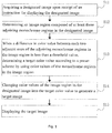
- Fig. 1 is a flowchart showing an image displaying method according to an exemplary embodiment.
- the image displaying method as shown in Fig. 1 is applicable to a smart device (i.e. it may be implemented by a smart device).
- the image displaying method according to the present invention can prevent sharp change of color while a soft screen with poor performance displays regions of similar colors in an image.
- the method comprises the following steps.
- step S11 a designated image is acquired upon receipt of an instruction for displaying the designated image.
- the method according to the present invention is applicable to a smart device having a screen, such as a smart TV, a smart mobile phone, a tablet computer or a smart watch.
- a user To view a designated image stored in a smart device, a user needs to input an instruction for displaying the designated image onto the smart device. Upon receipt of the instruction for displaying the designated image, the smart device reads from its hard disk the designated image stored previously.
- step S12 an image region composed of at least three adjoining monochrome regions in the designated image is determined.
- a monochrome region is composed of a plurality of pixels having the same color value and located at adjoining positions.
- the color value can be expressed in RGB system.
- the monochrome region is composed of 6 pixels arranged in 2 lines and 3 columns and the 6 pixels in 2 lines and 3 columns are all pure red, namely, the color value of these 6 pixels is RGB (255, 0, 0).
- An image region is composed of at least three monochrome regions.
- an image region A includes 4 adjoining monochrome regions.
- the first monochrome region is composed of 6 pixels in 2 lines and 3 columns and the 6 pixels in 2 lines and 3 columns are all pure red, namely, the color value of these 6 pixels is RGB (255, 0, 0).
- the second monochrome region is composed of 4 pixels in 2 lines and 2 columns and the 4 pixels in 2 lines and 2 columns are all red, namely, the color value of the 4 pixels is RGB (240, 0, 0).
- the third monochrome region is composed of 4 pixels in 2 lines and 2 columns and the 4 pixels in 2 lines and 2 columns are all red, namely, the color value of the 4 pixels is RGB (230, 0, 0).
- the fourth monochrome region is composed of 6 pixels in 2 lines and 3 columns and the 6 pixels in 2 lines and 3 columns are all red, namely, the color value of the 6 pixels is RGB (220, 0, 0).
- the image region A is composed of the above 4 adjoining monochrome regions and includes a total of 20 pixels.
- the smart device may determine an image region composed of at least three adjoining monochrome regions in the designated image. After determining the image region composed of at least three adjoining monochrome regions, the smart device acquires color values for the respective monochrome regions in the image region. For example, it is assumed that the image region A acquired by the smart device includes 4 adjoining monochrome regions, the color value of the first monochrome region is RGB (255, 0, 0), the color value of the second monochrome region is RGB (240, 0, 0), the color value of the third monochrome region is RGB (230, 0, 0) and the color value of the fourth monochrome region is RGB (220, 0, 0). Then, the smart device acquires the color values of these four monochrome regions respectively, which are RGB (255, 0, 0), RGB (240, 0, 0), RGB (230, 0, 0) and RGB (220, 0, 0) respectively.
- step S13 when a difference in color value between each two adjacent ones of the adjoining monochrome regions in the image region is less than a threshold value, a target color value is determined in accordance with a preset scheme by using color values of the monochrome regions in the image region.
- the threshold is a preset color value.
- the threshold value is preset to RGB (20, 20, 20).
- the smart device determines whether a difference in color value between each two adjacent ones of the adjoining monochrome regions in the image region is less than a threshold value.
- the smart device determines that the difference in color value between each two adjacent ones of the adjoining monochrome regions in the image region is less than the threshold value, it indicates that the adjoining monochrome regions in the image region have similar color values.
- some poor-performance soft screens may display some monochrome regions in the image region of the designated image in the same color, causing unsmooth color transition in the image region and sharp change of color.
- the smart devices determines that the difference in color value between each two adjacent ones of the adjoining monochrome region in the image region is less than the threshold value, the smart devices then determines a target color value by using color values of the monochrome regions in the image region, so as to guarantee that each of the monochrome regions in the image region adopts the target color value and accordingly avoid sharp change of color in the image region.
- the smart device determines an image region A composed of 6 adjoining monochrome regions in the designated image.
- the color value of the first monochrome region A1 is RGB (250, 0, 0).
- the color value of the second monochrome region A2 is RGB (240, 0, 0).
- the color value of the third monochrome region A3 is RGB (230, 0, 0).
- the color value of the fourth monochrome region is RGB (220, 0, 0).
- the color value of the fifth monochrome region is RGB (210, 0, 0).
- the color value of the sixth monochrome region is RGB (200, 0, 0).
- the smart device may calculate a difference in color value between each two adjacent ones of adjoining monochrome regions in the image region and determine whether the difference is less than a threshold value of RGB (20, 20, 20). It is found through calculation that the difference in color value between each two adjacent monochrome regions in the image region A of the designated image is equal to RGB (10, 0, 0), which is less than the threshold value RGB (20, 20, 20). This means the adjoining monochrome regions in the image region have similar color values.
- the smart device determines the target color value in accordance with a preset scheme by using the color values of the monochrome regions in the image region, thereby guaranteeing that each monochrome region in the image region adopts the target color value and accordingly avoiding sharp change of color in the image region.
- the preset scheme is to calculate an average value of the color values of the monochrome regions in the image region and then determine the average value as the target color value.
- the average value of the color values of the monochrome regions in the image region is calculated.
- the average value is determined as the target color value.
- the smart device determines an image region A composed of 6 adjoining monochrome regions in the designated image.
- the color value of the first monochrome region A1 is RGB (250, 0, 0).
- the color value of the second monochrome region A2 is RGB (240, 0, 0).
- the color value of the third monochrome region A3 is RGB (230, 0, 0).
- the color value of the fourth monochrome region is RGB (220, 0, 0).
- the color value of the fifth monochrome region is RGB (210, 0, 0).
- the color value of the sixth monochrome region is RGB (200, 0, 0).
- the preset scheme consists in deriving the target color value from a maximal color value and a minimal color value in the image region and a preset coefficient.
- the maximal color value and the minimal color value in the image region are acquired.
- a difference between the maximal color value and the minimal color value in the image region is calculated as a first color value.
- a product of the first color value and the preset coefficient is calculated as a second color value.
- a sum of the minimal color value and the second color value is calculated as the target color value.
- the preset coefficient is 0.6. It is assumed that the smart device determines an image region A composed of 6 adjoining monochrome regions in the designated image.
- the color value of the first monochrome region A1 is RGB (250, 0, 0).
- the color value of the second monochrome region A2 is RGB (240, 0, 0).
- the color value of the third monochrome region A3 is RGB (230, 0, 0).
- the color value of the fourth monochrome region is RGB (220, 0, 0).
- the color value of the fifth monochrome region is RGB (210, 0, 0).
- the color value of the sixth monochrome region is RGB (200, 0, 0).
- the smart device starts to acquire the maximal color value RGB (250, 0, 0) and the minimal color value RGB (200, 0, 0) in the image region.
- RGB (200, 0, 0) +RGB (30, 0, 0) RGB (230, 0, 0).
- step S14 color values of the image region in the designated image is changed into the target color value to generate a target image.
- the smart device after determining the target value from the color values of the monochrome region in the image region, changes the color values of the image region in the designated image into the target color value so as to generate a target image.
- the target image differs from the designated image in that the color value of the image region in the target image is the target color value. Other parts of the target image are same as those of the designated image.
- step S15 the target image is displayed.
- the smart device displays the target image on its display screen. Even if the display screen of the smart device is a poor-performance soft screen, no sharp change of color occurs when the target image is displayed.
- a designated image before a designated image is displayed, it is required to determine an image region composed of at least three monochrome regions in the designated image in advance. When it is determined that a difference in color value between each two adjacent ones of the adjoining monochrome regions in the image region is less than a threshold value, it indicates that the adjoining monochrome regions in the image region have similar colors.
- a target color value is determined in accordance with a preset scheme by using color values of the monochrome regions in the image region, so as to generate and display a target image in which the color value of the image region is the target color value, thereby guaranteeing that no sharp change of color occurs when the target image is displayed.
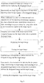
- Fig. 2 is a flowchart showing another image displaying method according to an exemplary embodiment.
- the image displaying method as shown in Fig.2 is applicable to a smart device (i.e. may be implemented by a smart device).
- the embodiment shown in Fig. 2 is a variant of the embodiment shown in Fig. 1 .
- description and explanation of the embodiment shown in Fig. 1 can be referred to.
- the method shown in Fig. 2 comprises the following steps.
- Step S21 a designated image is acquired upon receipt of an instruction for displaying the designated image.
- step S22 an image region composed of at least three adjoining monochrome regions in the designated image is determined.
- step S23 when a difference in color value between each two adjacent ones of the adjoining monochrome regions in the image region is less than a threshold value, a target color value is determined in accordance with a preset scheme by using color values of the monochrome regions in the image region.
- step S24 color values of the image region in the designated image are changed into the target color value to generate a target image.
- step S26 the target image is stored.
- the smart device can store the target image into its disk, so as to quickly determine the target image upon receipt of an instruction for displaying the designated image without having to repeat the above steps.
- the smart device after the smart device has stored the target image, it also needs to determine a correspondence relation between the designated image and the target image. In accordance with the correspondence relation between the designated image and the target image, the smart device can quickly find the target image corresponding to the designated image from the disk upon receipt of an instruction for displaying the designated image and then display the target image. Accordingly, time can be saved.
- step S28 the target image corresponding to the designated image is determined based on the correspondence relation between the designated image and the target image upon receipt of an instruction for displaying the designated image.
- Fig. 3 is a flowchart showing a further image displaying method according to an exemplary embodiment.
- the image displaying method as shown in Fig. 3 is applicable to a smart device (i.e. may be implemented by a smart device).
- the embodiment shown in Fig. 3 is a variant of the embodiment shown in Fig. 1 .
- description and explanation of the embodiment shown in Fig. 1 can be referred to.
- the method shown in Fig. 3 comprises the following steps.
- Step S31 a designated image is acquired upon receipt of an instruction for displaying the designated image.
- step S32 an image region composed of at least three adjoining monochrome regions in the designated image is determined.
- step S33 when a difference in color value between each two adjacent ones of the adjoining monochrome regions in the image region is less than a threshold value, a target color value is determined in accordance with a preset scheme by using color values of the monochrome regions in the image region.
- step S34 color values of image region in the designated image are changed into the target color value to generate a target image.
- step S35 the target image is displayed.
- step S37 a correspondence relation between the designated image and the target image is established.
- the smart device after the smart device has stored the target image, it also needs to determine a correspondence relation between the designated image and the target image. In accordance with the correspondence relation between the designated image and the target image, the smart device can quickly find the target image corresponding to the designated image from the disk upon receipt of an instruction for deleting the designated image. Accordingly, time can be saved.
- step S38 the target image corresponding to the designated image is determined based on the correspondence relation between the designated image and the target image upon receipt of an instruction for deleting the designated image.
- the smart device when the smart device receives an instruction for deleting the designated image, it indicates that the user neither needs the designated image nor the target image.
- the smart device can determine the previously stored target image corresponding to the designated image based on the correspondence relation between the designated image and the target image.
- step S39 the designated image and the target image are deleted.
- the smart device can delete the designated image and the target image.
- Fig. 4 is a flowchart showing a further image displaying method according to an exemplary embodiment.
- the method as shown in Fig. 4 is applicable to a smart device (i.e. may be implemented by a smart device).
- the embodiment shown in Fig. 4 is a variant of the embodiment shown in Fig. 1 .
- description and explanation of the embodiment shown in Fig. 1 can be referred to.
- the method shown in Fig. 4 comprises the following steps.
- Step S41 a designated image is acquired upon receipt of an instruction for displaying the designated image.
- step S42 a type of a display device for displaying the designated image is determined.
- the smart device determines a type of a display device for displaying the designated images.
- step S43 it is judged whether the display device for displaying the designated image is a soft screen.
- step S45 is executed.
- step S44 is executed.
- step S45 when the smart device judges that the display device for displaying the designated image is a soft screen, it indicates that the soft screen may display similar colors in the image as the same color when displaying the designated image. Accordingly, regions of similar colors in the image look unnatural. To avoid this, it is required to execute step S45.
- step S44 can be executed so that the display device directly displays the designated image.
- step S44 the display device is used to display the designated image.
- step S45 an image region composed of at least three adjoining monochrome regions in the designated image is determined.
- step S46 when a difference in color value between each two adjacent ones of the adjoining monochrome regions in the image region is less than a threshold value, a target color value is determined in accordance with a preset scheme by using color values of the monochrome regions in the image region.
- step S47 color values of image region in the designated image are changed into the target color value to generate a target image.
- step S48 the target image is displayed.
- Fig. 5 is the schematic diagram showing an image displaying device according to an exemplary embodiment.
- the image displaying device according to the present invention can prevent sharp change of color from occurring when a poor-performance soft screen displays regions of similar colors in an image.
- the device comprises an acquiring module 11, a first determining module 12, a second determining module 13, a changing module 14 and a first display module 15.
- the acquiring module 11 is configured to acquire a designated image upon receipt of an instruction for displaying the designated image.
- the first determining module 12 is configured to determine an image region composed of at least three adjoining monochrome regions in said designated image.
- the second determining module 13 is configured to determine a target color value in accordance with a preset scheme by using color values of the monochrome regions in said image region, when a difference in color value between each two adjacent ones of the adjoining monochrome regions in said image region is less than a threshold value.
- the changing module 14 is configured to change color values of said image region in said designated image into said target color value so as to generate a target image.
- the first display module 15 is configured to display said target image.
- Fig. 6 is a schematic diagram showing another image displaying device according to an exemplary embodiment.
- the image displaying device according to the present invention can prevent sharp change of color from occurring when a poor-performance soft screen displays regions of similar colors in an image.
- the device comprises an acquiring module 21, a first determining module 22, a second determining module 23, a changing module 24, a first display module 25, a first storage module 26, a first establishing module 27, a third determining module 28 and a second display module 29.
- the acquiring module 21 is configured to acquire a designated image upon receipt of an instruction for displaying the designated image.
- the first determining module 22 is configured to determine an image region composed of at least three adjoining monochrome regions in said designated image.
- the second determining module 23 is configured to determine a target color value in accordance with a preset scheme by using color values of the monochrome region in said image region when a difference in color value between each two adjacent ones of the adjoining monochrome regions in said image region is less than a threshold value.
- the changing module 24 is configured to change color values of the image region in the designated image into the target color value so as to generate a target image.
- the first display module 25 is configured to display said target image.
- the first storage module 26 is configured to store said target image.
- the first establishing module 27 is configured to establish a correspondence relation between the designated image and the target image.
- the third determining module 28 is configured to determine the target image corresponding to the designated image based on the correspondence relation between the designated image and the target image upon receipt of an instruction for displaying the designated image.
- the second display module 29 is configured to display the target image.
- Fig. 7 is a schematic diagram showing a further image displaying device according to an exemplary embodiment.
- the image displaying device according to the present invention prevents sharp change of color from occurring when a poor-performance soft screen displays regions of similar colors in an image.
- the device comprises an acquiring module 31, a first determining module 32, a second determining module 33, a changing module 34, a first display module 35, a second storage module 36, a second establishing module 37, a fourth determining module 38 and a deletion module 39.
- the acquiring module 31 is configured to acquire a designated image upon receipt of an instruction for displaying the designated image.
- the first determining module 32 is configured to determine an image region composed of at least three adjoining monochrome regions in the designated image.
- the second determining module 33 is configured to determine a target color value in accordance with a preset scheme by using color values of the monochrome regions in the image region when a difference in color value between each two adjacent ones of the adjoining monochrome regions in the image region is less than a threshold value.
- the changing module 34 is configured to change color values of the image region in the designated image into the target color value so as to generate a target image.
- the first display module 35 is configured to display the target image.
- the second storage module 36 is configured to store the target image.
- the second establishing module 37 is configured to establish a correspondence relation between the designated image and the target image.
- the fourth determining module 38 is configured to determine the target image corresponding to the designated image based on the correspondence relation between the designated image and the target image upon receipt of an instruction for deleting the designated image.
- the deletion module 39 is configured to delete the designated image and the target image.
- Fig. 8 is a schematic diagram showing a further image displaying device according to an exemplary embodiment.
- the image displaying device according to the present invention prevents sharp change of color from occurring when a poor-performance soft screen displays regions of similar colors in an image.
- the device comprises an acquiring module 41, a first determining module 42, a second determining module 43, a changing module 44, a first display module 45, a fifth determining module 46, a judging module 47, a triggering module 48 and a third display module 49.
- the acquiring module 41 is configured to acquire a designated image upon receipt of an instruction for displaying the designated image.
- the first determining module 42 is configured to determine an image region composed of at least three adjoining monochrome regions in the designated image.
- the second determining module 43 is configured to determine a target color value in accordance with a preset scheme by using color values of the monochrome regions in the image region when a difference in color value between each two adjacent ones of the adjoining monochrome regions in the image region is less than a threshold value.
- the changing module 44 is configured to change color values of the image region in the designated image into the target color value so as to generate a target image.
- the first display module 45 is configured to display the target image.
- the fifth determining module 46 is configured to determine a type of a display device for displaying said designated image
- the judging module 47 is configured to judge whether the display device for displaying said designated image is a soft screen.
- the triggering module 48 is configured to trigger the first determining module 42 when the display device for displaying the designated image is a soft screen.
- the third display module 49 is configured to display the designated image by using the display device when the display device for displaying the designated image is not a soft screen.
- Fig. 9 is a schematic diagram showing a further image displaying device according to an exemplary embodiment.
- the image displaying device according to the present invention prevents sharp change of color from occurring when a poor-performance soft screen displays regions of similar colors in an image.
- the device comprises an acquiring module 51, a first determining module 52, a second determining module 53, a changing module 54, and a first display module 55.
- the second determining module 53 includes a first calculation submodule 531 and a determining submodule 532.
- the acquiring module 51 is configured to acquire a designated image upon receipt of an instruction for displaying the designated image.
- the first determining module 52 is configured to determine an image region composed of at least three adjoining monochrome regions in the designated image.
- the second determining module 53 is configured to determine a target color value in accordance with a preset scheme by using color values of the monochrome regions in the image region when a difference in color values between each two adjacent ones of the adjoining monochrome regions in the image region is less than a threshold value.
- the changing module 54 is configured to change color values of the image region of the designated image into the target color value so as to generate a target image.
- the first display module 55 is configured to display the target image.
- the first calculation submodule 531 is configured to calculate an average value of the color values of the monochrome regions in the image region.
- the determining submodule 532 is configured to determine said average value as the target color value.
- Fig. 10 is a schematic diagram showing a further image displaying device according to an exemplary embodiment.
- the image displaying device according to the present invention prevents sharp change of color from occurring when a poor-performance soft screen displays regions of similar colors in an image.
- the device comprises an acquiring module 61, a first determining module 62, a second determining module 63, a changing module 64, a first display module 65.
- the second determining module 63 includes an acquiring submodule 631, a second calculation submodule 632, a third calculation submodule 633 and a fourth calculation submodule 634.
- the acquiring module 61 is configured to acquire a designated image upon receipt of an instruction for displaying the designated image.
- the first determining module 62 is configured to determine an image region composed of at least three adjoining monochrome regions in the designated image.
- the second determining module 63 is configured to determine a target color value in accordance with a preset scheme by using color values of the monochrome regions in the image region when a difference in color value between each two adjacent ones of the adjoining monochrome regions in the image region is less than a threshold value.
- the changing module 64 is configured to change color values of the image region in the designated image into the target color value so as to generate a target image.
- the first display module 65 is configured to display the target image.
- the acquiring submodule 631 is configured to acquire a maximal color value and a minimal color value in said image region.
- the second calculation submodule 632 is configured to calculate a difference between said maximal color value and said minimal color value in said image region as a first color value.
- the third calculation submodule 633 is configured to calculate a product of said first color value and a preset coefficient as a second color value.
- the fourth calculation submodule 634 is configured to calculate a sum of the minimal color value and the second color value as the target color value.
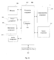
- Fig. 11 is a block diagram showing an image displaying device 800 according to an exemplary embodiment.
- the device 800 may be a mobile phone, a computer, a digital broadcast terminal, a message transceiving device, a game console, a tablet device, a medical equipment, a fitness equipment, a personal digital assistant, and the like.
- the device 800 may include one or more of the following components: a processing component 802, a memory 804, a power component 806, a multimedia component 808, an audio component 810, an input/output (I/O) interface 812, a sensor component 814 and a communication component 816.
- a processing component 802 a memory 804, a power component 806, a multimedia component 808, an audio component 810, an input/output (I/O) interface 812, a sensor component 814 and a communication component 816.
- the processing component 802 typically controls overall operations of the device 800, such as the operations associated with display, telephone calls, data communications, camera operations, and recording operations.
- the processing component 802 may include one or more processors 820 to execute instructions to perform all or part of the steps in the above described methods.
- the processing component 802 may include one or more modules which facilitate the interaction between the processing component 802 and other components.
- the processing component 802 may include a multimedia module to facilitate the interaction between the multimedia component 808 and the processing component 802.
- the memory 804 is configured to store various types of data to support the operation of the device 800. Examples of such data include instructions for any applications or methods operated on the device 800, contact data, phonebook data, messages, images, video, etc.
- the memory 804 may be implemented using any type of volatile or non-volatile memory devices, or a combination thereof, such as a static random access memory (SRAM), an electrically erasable programmable read-only memory (EEPROM), an erasable programmable read-only memory (EPROM), a programmable read-only memory (PROM), a read-only memory (ROM), a magnetic memory, a flash memory, a magnetic or optical disk.
- SRAM static random access memory
- EEPROM electrically erasable programmable read-only memory
- EPROM erasable programmable read-only memory
- PROM programmable read-only memory
- ROM read-only memory
- magnetic memory a magnetic memory
- flash memory a flash memory
- magnetic or optical disk a magnetic or optical
- the power component 806 supplies power to various components of the device 800.
- the power component 806 may include a power management system, one or more power sources, and any other components associated with the generation, management, and distribution of power in the device 800.
- the multimedia component 808 includes a screen providing an output interface between the device 800 and the user.
- the screen may include a liquid crystal display (LCD) and a touch panel (TP). If the screen includes the touch panel, the screen may be implemented as a touch screen to receive input signals from the user.
- the touch panel includes one or more touch sensors to sense touches, slips, and gestures on the touch panel. The touch sensors may not only sense a boundary of a touch or slip action, but also sense a period of time and a pressure associated with the touch or slip action.
- the multimedia component 808 includes a front camera and/or a rear camera. The front camera and the rear camera may receive external multimedia data while the device 800 is in an operation mode, such as a photographing mode or a video mode. Each of the front camera and the rear camera may be a fixed optical lens system or have focus and optical zoom capability.
- the audio component 810 is configured to output and/or input audio signals.
- the audio component 810 includes a microphone ("MIC") configured to receive an external audio signal when the terminal device 800 is in an operation mode, such as a call mode, a recording mode, and a voice recognition mode.
- the received audio signal may be further stored in the memory 804 or transmitted via the communication component 816.
- the audio component 810 further includes a speaker to output audio signals.
- the I/O interface 812 provides an interface between the processing component 802 and peripheral interface modules, such as a keyboard, a click wheel, buttons, and the like.
- the buttons may include, but are not limited to, a home button, a volume button, a starting button, and a locking button.
- the sensor component 814 includes one or more sensors to provide status assessments of various aspects of the device 800. For instance, the sensor component 814 may detect an open/closed status of the device 800, relative positioning of components, e.g., the display and the keypad, of the device 800, a change in position of the device 800 or a component of the device 800, a presence or absence of user contact with the device 800, an orientation or an acceleration/deceleration of the device 800, and a change in temperature of the device 800.
- the sensor component 814 may include a proximity sensor configured to detect the presence of nearby objects without any physical contact.
- the sensor component 814 may also include a light sensor, such as a CMOS or CCD image sensor, for use in imaging applications.
- the sensor component 814 may also include an accelerometer sensor, a gyroscope sensor, a magnetic sensor, a pressure sensor, or a temperature sensor.
- the communication component 816 is configured to facilitate communication, wired or wirelessly, between the device 800 and other devices.
- the device 800 can access a wireless network based on a communication standard, such as WiFi, 2G, or 3G, or a combination thereof.
- the communication component 816 receives a broadcast signal or broadcast associated information from an external broadcast management system via a broadcast channel.
- the communication component 816 further includes a near field communication (NFC) module to facilitate short-range communications.
- the NFC module may be implemented based on a radio frequency identification (RFID) technology, an infrared data association (IrDA) technology, an ultra-wideband (UWB) technology, a Bluetooth (BT) technology, and other technologies.
- RFID radio frequency identification
- IrDA infrared data association
- UWB ultra-wideband
- BT Bluetooth
- the device 800 may be implemented with one or more application specific integrated circuits (ASICs), digital signal processors (DSPs), digital signal processing devices (DSPDs), programmable logic devices (PLDs), field programmable gate arrays (FPGAs), controllers, micro-controllers, microprocessors, or other electronic components, for performing the above described methods.
- ASICs application specific integrated circuits
- DSPs digital signal processors
- DSPDs digital signal processing devices
- PLDs programmable logic devices
- FPGAs field programmable gate arrays
- controllers micro-controllers, microprocessors, or other electronic components, for performing the above described methods.
- non-transitory computer-readable storage medium including instructions, such as the memory 804 including instructions.
- the instructions are executable by the processor 820 in the device 800 to perform the above-described methods.
- the non-transitory computer-readable storage medium may be a ROM, a RAM, a CD-ROM, a magnetic tape, a floppy disc, an optical data storage device, and the like.
- the device or mobile terminal When instructions in the storage medium are executed by a processor of a device such as a mobile terminal, the device or mobile terminal is enabled to perform an image displaying method, which comprises: upon receipt of an instruction for displaying a designated image, acquiring said designated image; determining an image region composed of at least three adjoining monochrome regions in said designated image; when a difference in color value between each two adjacent ones of the adjoining monochrome regions is less than a threshold value, determine a target color value in accordance with a preset scheme by using color values of the monochrome regions in said image region; changing color values of said image region in said designated image into said target color value to generate a target image; displaying said target image.
Landscapes
- Engineering & Computer Science (AREA)
- Theoretical Computer Science (AREA)
- General Physics & Mathematics (AREA)
- Physics & Mathematics (AREA)
- Computer Hardware Design (AREA)
- Databases & Information Systems (AREA)
- General Engineering & Computer Science (AREA)
- Data Mining & Analysis (AREA)
- Chemical & Material Sciences (AREA)
- Crystallography & Structural Chemistry (AREA)
- Human Computer Interaction (AREA)
- Computer Vision & Pattern Recognition (AREA)
- Controls And Circuits For Display Device (AREA)
- User Interface Of Digital Computer (AREA)
- Color Image Communication Systems (AREA)
- Image Processing (AREA)
- Image Analysis (AREA)
- Transforming Electric Information Into Light Information (AREA)
- Compression Or Coding Systems Of Tv Signals (AREA)
Abstract
Description
- The present invention relates to the technical field of communications and, more particularly, to an image displaying method, an image displaying device, a computer program and a recording medium.
- LCD panels may be divided into two types in terms of display technology: hard screens and soft screens. Soft screens, which mainly refer to VA (Vertical Alignment) -type panels, are characterized in that, when a soft screen is touched by a hand, a water ripple effect will appear on the soft screen.
- Owing to poor display performance of some soft screens, when an image is displayed using such a soft screen, similar colors in the image may be displayed as one color. Accordingly, some regions of transitional colors are lost from regions of similar colors in the image, making it look unnatural. For example, it is assumed that a region B in an image A is a red region, from left to right the color of the red region B gradually changes to dark red from light red and the change of color in the red region B is smooth. However, owing to poor performance of some soft screens, sharp change of color occurs when such a soft screen displays the red region B of the image A. That is, such a soft screen will display the original red region B in the image A where the change of color is gradual and smooth as a red region B where the change of color is sharp and remarkable.
- Therefore, in the above related technology, some soft screens with poor performance will display an image containing similar colors as an image of the same color. Accordingly, sharp change of color occurs and the image looks unnatural.
- This Summary is provided to introduce a selection of concepts in a simplified form that are further described below in the Detailed Description. This Summary is not intended to identify key features or essential features of the claimed subject matter, nor is it intended to be used to limit the scope of the claimed subject matter.
- In order to overcome problems with the related technology, the invention provides an image displaying method, an image displaying device, a computer program and a recording medium, whereby no sharp change of color occurs when a soft screen with poor performance displays regions of similar colors in an image.
- According to a first aspect of embodiments of the present invention, there is provided an image displaying method. The method comprises the steps of:
- acquiring a designated image upon receipt of an instruction for displaying said designated image;
- determining an image region composed of at least three adjoining monochrome regions in the designated image;
- when a difference in color value between each two adjacent ones of the adjoining monochrome regions in the image region is less than a threshold value, determining a target color value according to a preset scheme by using color values of the monochrome regions in the image region;
- changing color values of the image region in the designated image into the target color value to generate a target image;
- displaying said target image.
- In a particular embodiment, said method further comprises:
- storing said target image;
- establishing a correspondence relation between said designated image and said target image;
- upon receipt of an instruction for displaying said designated image, determining said target image corresponding to said designated image based on the correspondence relation between said designated image and said target image;
- displaying said target image.
- In another particular embodiment, said method further comprises:
- storing said target image;
- establishing a correspondence relation between said designated image and said target image;
- upon receipt of an instruction for deleting said designated image, determining said target image corresponding to said designated image based on the correspondence relation between said designated image and said target image;
- deleting said designated image and said target image.
- In a particular embodiment, said method further comprises: after acquiring said designated image,
determining a type of a display device for displaying said designated image;
judging whether the display device for displaying said designated image is a soft screen;
when the display device for displaying said designated image is a soft screen, triggering the step of determining the image region composed of the at least three monochrome regions in said designated image;
when the display device for displaying said designated image is not a soft screen, displaying said designated image by utilizing said display device. - In a particular embodiment, said step of determining the target color value in accordance with the preset scheme by utilizing the color values of the monochrome region in said image region comprises:
- calculating an average value of the color values of the monochrome regions in said image region;
- determining said average value as the target color value.
- In a particular embodiment, said step of determining the target color value in accordance with the preset scheme by using the color values of the monochrome region in said image region comprises:
- acquiring a maximal color value and a minimal color value in said image region;
- calculating a difference between said maximal color value and said minimal color value in said image region as a first color value;
- calculating a product of said first color value and a preset coefficient as a second color value;
- calculating a sum of said minimal color value and said second color value as the target color value.
- According to a second aspect of embodiments of the present invention, there is provided an image displaying device. The device comprises:
- an acquiring module configured to acquire a designated image upon receipt of an instruction for displaying the designated image;
- a first determining module configured to determine an image region composed of at least three adjoining monochrome regions in said designated image;
- a second determining module configured to determine a target color value in accordance with a preset scheme by using color values of monochrome regions in said image region, when a difference in color value between each two adjacent ones of the adjoining monochrome regions in said image region is less than a threshold value;
- a changing module configured to change color values of said image region in said designated image into said target color value so as to generate a target image;
- a first display module configured to display said target image.
- In a particular embodiment, said device further comprises:
- a first storage module configured to store said target image;
- a first establishing module configured to establish a correspondence relation between said designated image and said target image;
- a third determining module configured to determine said target image corresponding to said designated image based on the correspondence relation between said designated image and said target image, upon receipt of an instruction for displaying said designated image;
- a second display module configured to display said target image.
- In a particular embodiment, said device further comprises:
- a second storage module configured to store said target image;
- a second establishing module configured to establish a correspondence relation between said designated image and said target image;
- a fourth determining module configured to determine said target image corresponding to said designated image based on the correspondence relation between said designated image and said target image, upon receipt of an instruction for deleting said designated image;
- a deletion module configured to delete said designated image and said target image.
- In a particular embodiment, said device further comprises:
- a fifth determining module configured to determine a type of a display device for displaying said designated image;
- a judging module configured to judge whether the display device for displaying said designated image is a soft screen;
- a triggering module configured to trigger said first determining module when the display device for displaying said designated image is a soft screen;
- a third display module configured to display said designated image by using said display device when the display device for displaying said designated image is not a soft screen.
- In a particular embodiment, said second determining module comprises:
- a first calculation submodule configured to calculate average value of color values of each monochrome region in said image region;
- a determining submodule configured to determine said average value as the target color value.
- In a particular embodiment, said second determining module comprises:
- an acquiring submodule configured to acquire a maximal color value and a minimal color value in said image region;
- a second calculation submodule configured to calculate a difference between said maximal color value and said minimal color value in said image region as a first color value;
- a third calculation submodule configured to calculate a product of said first color value and a preset coefficient as a second color value;
- a fourth calculation submodule configured to calculate a sum of said minimal color value and said second color value as the target color value.
- According to a third aspect of the embodiments of the present invention, there is provided an image displaying device. The device comprises:
- a processor;
- a memory configured to store commands which are executable by the processor to:
- acquire a designated image upon receipt of an instruction for displaying a designated image;
- determine an image region composed of at least three adjoining monochrome regions in the designated image;
- when a difference in color value between each two adjacent ones of the adjoining monochrome regions in the image region is less than a threshold value, determine a target color value according to a preset scheme by using color values of the monochrome region in the image region;
- change color values of the image region in the designated image into the target color value to generate a target image;
- display said target image.
- In one particular embodiment, the steps of the image displaying method are determined by computer program instructions.
- Consequently, according to a fourth aspect, the invention is also directed to a computer program for executing the steps of an image displaying method as described above when this program is executed by a computer.
- This program can use any programming language and take the form of source code, object code or a code intermediate between source code and object code, such as a partially compiled form, or any other desirable form.
- The invention is also directed to a computer-readable information medium containing instructions of a computer program as described above.
- The information medium can be any entity or device capable of storing the program. For example, the support can include storage means such as a ROM, for example a CD ROM or a microelectronic circuit ROM, or magnetic storage means, for example a diskette (floppy disk) or a hard disk.
- Alternatively, the information medium can be an integrated circuit in which the program is incorporated, the circuit being adapted to execute the method in question or to be used in its execution.
- The technical solutions according to the embodiments of the present invention can achieve the following advantageous effect. In the solutions according to the invention, before a designated image is displayed, an image region composed of at least three monochrome regions in the designated image is determined. When it is determined that a difference in color value between each two adjacent ones of the adjoining monochrome regions in the image region is less than a threshold value, it indicates that the adjoining monochrome regions in the image region have similar colors. In order to avoid sharp change of color when a soft screen with poor performance displays the monochrome regions of the image region in the designated image, color values of the monochrome regions in the image region are used to determine a target color value in accordance with a preset scheme, so as to generate and display a target image in which the color value of the image region is the target color value, thereby guaranteeing that no sharp change of color occurs when the target image is displayed.
- It should be understood that the general description above and the detailed description below are merely illustrative rather than limitative.
- Accompanying drawings herein are incorporated into the specification as a part of it, for illustrating embodiments according to the present invention and for explaining principles of the present invention together with the description.
-
Fig. 1 is a flowchart showing an image displaying method according to an exemplary embodiment. -
Fig. 2 is a flowchart showing another image displaying method according to an exemplary embodiment. -
Fig. 3 is a flowchart showing a further image displaying method according to an exemplary embodiment. -
Fig. 4 is a flowchart showing a further image displaying method according to an exemplary embodiment. -
Fig. 5 is a schematic diagram showing an image displaying device according to an exemplary embodiment. -
Fig. 6 is a schematic diagram showing another image displaying device according to an exemplary embodiment. -
Fig. 7 is a schematic diagram showing a further image displaying device according to an exemplary embodiment. -
Fig. 8 is a schematic diagram showing a further image displaying device according to an exemplary embodiment. -
Fig. 9 is a schematic diagram showing a further image displaying device according to an exemplary embodiment. -
Fig. 10 is a schematic diagram showing a further image displaying device according to an exemplary embodiment. -
Fig. 11 is a block diagram showing an image displaying device according to an exemplary embodiment. - Here, detailed description will be given of exemplary embodiments, which are illustrated in the accompanying drawings. In the following description, when the accompanying drawings are referred to, like numbers in different drawings represent like elements unless otherwise specified. Implementations described in the following exemplary embodiments are not all possible implementations according to the invention. Instead, they are merely examples of devices and methods according to certain aspects of the invention as recited in the appended claims.
-
Fig. 1 is a flowchart showing an image displaying method according to an exemplary embodiment. The image displaying method as shown inFig. 1 is applicable to a smart device (i.e. it may be implemented by a smart device). The image displaying method according to the present invention can prevent sharp change of color while a soft screen with poor performance displays regions of similar colors in an image. The method comprises the following steps. - In step S11, a designated image is acquired upon receipt of an instruction for displaying the designated image.
- Here, the method according to the present invention is applicable to a smart device having a screen, such as a smart TV, a smart mobile phone, a tablet computer or a smart watch.
- To view a designated image stored in a smart device, a user needs to input an instruction for displaying the designated image onto the smart device. Upon receipt of the instruction for displaying the designated image, the smart device reads from its hard disk the designated image stored previously.
- In step S12, an image region composed of at least three adjoining monochrome regions in the designated image is determined.
- Here, a monochrome region is composed of a plurality of pixels having the same color value and located at adjoining positions. The color value can be expressed in RGB system. For example, it is assumed that the monochrome region is composed of 6 pixels arranged in 2 lines and 3 columns and the 6 pixels in 2 lines and 3 columns are all pure red, namely, the color value of these 6 pixels is RGB (255, 0, 0).
- An image region is composed of at least three monochrome regions. For example, it is assumed that an image region A includes 4 adjoining monochrome regions. The first monochrome region is composed of 6 pixels in 2 lines and 3 columns and the 6 pixels in 2 lines and 3 columns are all pure red, namely, the color value of these 6 pixels is RGB (255, 0, 0). The second monochrome region is composed of 4 pixels in 2 lines and 2 columns and the 4 pixels in 2 lines and 2 columns are all red, namely, the color value of the 4 pixels is RGB (240, 0, 0). The third monochrome region is composed of 4 pixels in 2 lines and 2 columns and the 4 pixels in 2 lines and 2 columns are all red, namely, the color value of the 4 pixels is RGB (230, 0, 0). The fourth monochrome region is composed of 6 pixels in 2 lines and 3 columns and the 6 pixels in 2 lines and 3 columns are all red, namely, the color value of the 6 pixels is RGB (220, 0, 0). Thus, the image region A is composed of the above 4 adjoining monochrome regions and includes a total of 20 pixels.
- After the smart device acquires the designated image, the smart device may determine an image region composed of at least three adjoining monochrome regions in the designated image. After determining the image region composed of at least three adjoining monochrome regions, the smart device acquires color values for the respective monochrome regions in the image region. For example, it is assumed that the image region A acquired by the smart device includes 4 adjoining monochrome regions, the color value of the first monochrome region is RGB (255, 0, 0), the color value of the second monochrome region is RGB (240, 0, 0), the color value of the third monochrome region is RGB (230, 0, 0) and the color value of the fourth monochrome region is RGB (220, 0, 0). Then, the smart device acquires the color values of these four monochrome regions respectively, which are RGB (255, 0, 0), RGB (240, 0, 0), RGB (230, 0, 0) and RGB (220, 0, 0) respectively.
- In step S13, when a difference in color value between each two adjacent ones of the adjoining monochrome regions in the image region is less than a threshold value, a target color value is determined in accordance with a preset scheme by using color values of the monochrome regions in the image region.
- Here, the threshold is a preset color value. For example, it is assumed that the threshold value is preset to RGB (20, 20, 20).
- When the smart device determines the image region composed of at least three adjoining monochrome regions in the designated image, the smart device determines whether a difference in color value between each two adjacent ones of the adjoining monochrome regions in the image region is less than a threshold value. When the smart device determines that the difference in color value between each two adjacent ones of the adjoining monochrome regions in the image region is less than the threshold value, it indicates that the adjoining monochrome regions in the image region have similar color values. When displaying the designated image, some poor-performance soft screens may display some monochrome regions in the image region of the designated image in the same color, causing unsmooth color transition in the image region and sharp change of color.
- Therefore, when the smart device determines that the difference in color value between each two adjacent ones of the adjoining monochrome region in the image region is less than the threshold value, the smart devices then determines a target color value by using color values of the monochrome regions in the image region, so as to guarantee that each of the monochrome regions in the image region adopts the target color value and accordingly avoid sharp change of color in the image region.
- For instance, it is assumed that the threshold value is preset to RGB (20, 20, 20), the smart device determines an image region A composed of 6 adjoining monochrome regions in the designated image. The color value of the first monochrome region A1 is RGB (250, 0, 0). The color value of the second monochrome region A2 is RGB (240, 0, 0). The color value of the third monochrome region A3 is RGB (230, 0, 0). The color value of the fourth monochrome region is RGB (220, 0, 0). The color value of the fifth monochrome region is RGB (210, 0, 0). The color value of the sixth monochrome region is RGB (200, 0, 0). Furthermore, the first monochrome region A1, the second monochrome region A2, the third monochrome region A3, the fourth monochrome region A4, the fifth monochrome region A5 and the sixth monochrome region A6 are connected in turn. Then, the smart device may calculate a difference in color value between each two adjacent ones of adjoining monochrome regions in the image region and determine whether the difference is less than a threshold value of RGB (20, 20, 20). It is found through calculation that the difference in color value between each two adjacent monochrome regions in the image region A of the designated image is equal to RGB (10, 0, 0), which is less than the threshold value RGB (20, 20, 20). This means the adjoining monochrome regions in the image region have similar color values. When the designated image is displayed on some poor-performance soft screens, some monochrome regions in the image region of the designated image may be displayed in the same color, causing unsmooth color transition in the image region and sharp change of color. Therefore, the smart device determines the target color value in accordance with a preset scheme by using the color values of the monochrome regions in the image region, thereby guaranteeing that each monochrome region in the image region adopts the target color value and accordingly avoiding sharp change of color in the image region.
- In addition, there is a plurality of implementations for determining the target color value in accordance with preset scheme by using the color values of the monochrome regions in the image region. In the following, two implementations will be described.
- In the first implementation, the preset scheme is to calculate an average value of the color values of the monochrome regions in the image region and then determine the average value as the target color value.
- In order to describe the first implementation more clearly, steps of the first implementation are briefly described below.
- In the first step, the average value of the color values of the monochrome regions in the image region is calculated.
- In the second step, the average value is determined as the target color value.
- For example, it is assumed that the smart device determines an image region A composed of 6 adjoining monochrome regions in the designated image. The color value of the first monochrome region A1 is RGB (250, 0, 0). The color value of the second monochrome region A2 is RGB (240, 0, 0). The color value of the third monochrome region A3 is RGB (230, 0, 0). The color value of the fourth monochrome region is RGB (220, 0, 0). The color value of the fifth monochrome region is RGB (210, 0, 0). The color value of the sixth monochrome region is RGB (200, 0, 0). Then, the smart device starts to calculate an average value of the color values of the 6 adjoining monochrome regions in the image region A, which is [RGB (250, 0, 0) + (240, 0, 0) + RGB (230, 0, 0) + RGB (220, 0, 0) + RGB (210, 0, 0) + RGB (200, 0, 0)]/6= RGB (225, 0, 0). Finally, the smart device determines the average value RGB (225, 0, 0) as the target color value.
- In the second implementation, the preset scheme consists in deriving the target color value from a maximal color value and a minimal color value in the image region and a preset coefficient.
- In order to describe the second implementation more clearly, steps of the second implementation are briefly described below.
- In the first step, the maximal color value and the minimal color value in the image region are acquired.
- In the second step, a difference between the maximal color value and the minimal color value in the image region is calculated as a first color value.
- In the third step, a product of the first color value and the preset coefficient is calculated as a second color value.
- In the fourth step, a sum of the minimal color value and the second color value is calculated as the target color value.
- For example, the preset coefficient is 0.6. It is assumed that the smart device determines an image region A composed of 6 adjoining monochrome regions in the designated image. The color value of the first monochrome region A1 is RGB (250, 0, 0). The color value of the second monochrome region A2 is RGB (240, 0, 0). The color value of the third monochrome region A3 is RGB (230, 0, 0). The color value of the fourth monochrome region is RGB (220, 0, 0). The color value of the fifth monochrome region is RGB (210, 0, 0). The color value of the sixth monochrome region is RGB (200, 0, 0). Then, the smart device starts to acquire the maximal color value RGB (250, 0, 0) and the minimal color value RGB (200, 0, 0) in the image region. Afterwards, a difference between the maximal color value RGB (250, 0, 0) and the minimal color value RGB (200, 0, 0) in the image region is calculated as a first color value which is RGB (250, 0, 0)-RGB (200, 0, 0) = RGB(50, 0, 0). Next, a product of the first color value RGB (50, 0, 0) and the preset coefficient 0.6 is calculated as the second color value which is RGB (50, 0, 0) x0.6= RGB (30, 0, 0). Thereafter, a sum of the minimal color value RGB (200, 0, 0) and the second color value RGB (30, 0, 0) is calculated as the target color value which is RGB (200, 0, 0) +RGB (30, 0, 0)= RGB (230, 0, 0).
- In step S14, color values of the image region in the designated image is changed into the target color value to generate a target image.
- Here, after determining the target value from the color values of the monochrome region in the image region, the smart device changes the color values of the image region in the designated image into the target color value so as to generate a target image. The target image differs from the designated image in that the color value of the image region in the target image is the target color value. Other parts of the target image are same as those of the designated image.
- In step S15, the target image is displayed.
- Here, the smart device displays the target image on its display screen. Even if the display screen of the smart device is a poor-performance soft screen, no sharp change of color occurs when the target image is displayed.
- In the embodiment shown in
Fig.1 , before a designated image is displayed, it is required to determine an image region composed of at least three monochrome regions in the designated image in advance. When it is determined that a difference in color value between each two adjacent ones of the adjoining monochrome regions in the image region is less than a threshold value, it indicates that the adjoining monochrome regions in the image region have similar colors. In order to avoid sharp change of color when a poor-performance soft screen displays the monochrome regions of the image region in the designated image, a target color value is determined in accordance with a preset scheme by using color values of the monochrome regions in the image region, so as to generate and display a target image in which the color value of the image region is the target color value, thereby guaranteeing that no sharp change of color occurs when the target image is displayed. -
Fig. 2 is a flowchart showing another image displaying method according to an exemplary embodiment. The image displaying method as shown inFig.2 is applicable to a smart device (i.e. may be implemented by a smart device). The embodiment shown inFig. 2 is a variant of the embodiment shown inFig. 1 . For the same part ofFig. 2 as that ofFig. 1 , description and explanation of the embodiment shown inFig. 1 can be referred to. The method shown inFig. 2 comprises the following steps. - In Step S21, a designated image is acquired upon receipt of an instruction for displaying the designated image.
- In step S22, an image region composed of at least three adjoining monochrome regions in the designated image is determined.
- In step S23, when a difference in color value between each two adjacent ones of the adjoining monochrome regions in the image region is less than a threshold value, a target color value is determined in accordance with a preset scheme by using color values of the monochrome regions in the image region.
- In step S24, color values of the image region in the designated image are changed into the target color value to generate a target image.
- In step S25, the target image is displayed.
- In step S26, the target image is stored.
- Here, after displaying the target image on its display screen, the smart device can store the target image into its disk, so as to quickly determine the target image upon receipt of an instruction for displaying the designated image without having to repeat the above steps.
- In step S27, a correspondence relation between the designated image and the target image is established.
- Here, after the smart device has stored the target image, it also needs to determine a correspondence relation between the designated image and the target image. In accordance with the correspondence relation between the designated image and the target image, the smart device can quickly find the target image corresponding to the designated image from the disk upon receipt of an instruction for displaying the designated image and then display the target image. Accordingly, time can be saved.
- In step S28, the target image corresponding to the designated image is determined based on the correspondence relation between the designated image and the target image upon receipt of an instruction for displaying the designated image.
- In step S29, the target image is displayed.
-
Fig. 3 is a flowchart showing a further image displaying method according to an exemplary embodiment. The image displaying method as shown inFig. 3 is applicable to a smart device (i.e. may be implemented by a smart device). The embodiment shown inFig. 3 is a variant of the embodiment shown inFig. 1 . For the same part ofFig. 3 as that ofFig. 1 , description and explanation of the embodiment shown inFig. 1 can be referred to. The method shown inFig. 3 comprises the following steps. - In Step S31, a designated image is acquired upon receipt of an instruction for displaying the designated image.
- In step S32, an image region composed of at least three adjoining monochrome regions in the designated image is determined.
- In step S33, when a difference in color value between each two adjacent ones of the adjoining monochrome regions in the image region is less than a threshold value, a target color value is determined in accordance with a preset scheme by using color values of the monochrome regions in the image region.
- In step S34, color values of image region in the designated image are changed into the target color value to generate a target image.
- In step S35, the target image is displayed.
- In step S36, the target image is stored.
- Here, after displaying the target image on its display screen, the smart device can store the target image into its disk, so as to quickly determine the target image upon receipt of the instruction for displaying the designated image without repeating the above steps.
- In step S37, a correspondence relation between the designated image and the target image is established.
- Here, after the smart device has stored the target image, it also needs to determine a correspondence relation between the designated image and the target image. In accordance with the correspondence relation between the designated image and the target image, the smart device can quickly find the target image corresponding to the designated image from the disk upon receipt of an instruction for deleting the designated image. Accordingly, time can be saved.
- In step S38, the target image corresponding to the designated image is determined based on the correspondence relation between the designated image and the target image upon receipt of an instruction for deleting the designated image.
- Here, when the smart device receives an instruction for deleting the designated image, it indicates that the user neither needs the designated image nor the target image. The smart device can determine the previously stored target image corresponding to the designated image based on the correspondence relation between the designated image and the target image.
- In step S39, the designated image and the target image are deleted.
- Here, after determining the target image corresponding to the designated image, the smart device can delete the designated image and the target image.
-
Fig. 4 is a flowchart showing a further image displaying method according to an exemplary embodiment. The method as shown inFig. 4 is applicable to a smart device (i.e. may be implemented by a smart device). The embodiment shown inFig. 4 is a variant of the embodiment shown inFig. 1 . For the same part ofFig. 4 as that ofFig. 1 , description and explanation of the embodiment shown inFig. 1 can be referred to. The method shown inFig. 4 comprises the following steps. - In Step S41, a designated image is acquired upon receipt of an instruction for displaying the designated image.
- In step S42, a type of a display device for displaying the designated image is determined.
- Owing to poor display performance of some soft screens, when an image is displayed with such a soft screen, similar colors in the image may be displayed as the same color, making regions of similar colors in the image looks unnatural. However, there is no such phenomenon for a hard screen. Therefore, after acquiring the designated image, the smart device determines a type of a display device for displaying the designated images.
- In step S43, it is judged whether the display device for displaying the designated image is a soft screen. When the display device for displaying the designated image is a soft screen, step S45 is executed. When the display device for displaying the designated image is not a soft screen, step S44 is executed.
- Here, when the smart device judges that the display device for displaying the designated image is a soft screen, it indicates that the soft screen may display similar colors in the image as the same color when displaying the designated image. Accordingly, regions of similar colors in the image look unnatural. To avoid this, it is required to execute step S45. When the smart device judges that the display device for displaying the designated image is not a soft screen, it indicates that the display device will not display similar colors in the image as the same color while displaying the designated image. Accordingly, step S44 can be executed so that the display device directly displays the designated image.
- In step S44, the display device is used to display the designated image.
- In step S45, an image region composed of at least three adjoining monochrome regions in the designated image is determined.
- In step S46, when a difference in color value between each two adjacent ones of the adjoining monochrome regions in the image region is less than a threshold value, a target color value is determined in accordance with a preset scheme by using color values of the monochrome regions in the image region.
- In step S47, color values of image region in the designated image are changed into the target color value to generate a target image.
- In step S48, the target image is displayed.
-
Fig. 5 is the schematic diagram showing an image displaying device according to an exemplary embodiment. The image displaying device according to the present invention can prevent sharp change of color from occurring when a poor-performance soft screen displays regions of similar colors in an image. Referring toFig. 5 , the device comprises an acquiring module 11, a first determiningmodule 12, a second determiningmodule 13, a changingmodule 14 and afirst display module 15. - The acquiring module 11 is configured to acquire a designated image upon receipt of an instruction for displaying the designated image.
- The first determining
module 12 is configured to determine an image region composed of at least three adjoining monochrome regions in said designated image. - The second determining
module 13 is configured to determine a target color value in accordance with a preset scheme by using color values of the monochrome regions in said image region, when a difference in color value between each two adjacent ones of the adjoining monochrome regions in said image region is less than a threshold value. - The changing
module 14 is configured to change color values of said image region in said designated image into said target color value so as to generate a target image. - The
first display module 15 is configured to display said target image. -
Fig. 6 is a schematic diagram showing another image displaying device according to an exemplary embodiment. The image displaying device according to the present invention can prevent sharp change of color from occurring when a poor-performance soft screen displays regions of similar colors in an image. Referring toFig. 6 , the device comprises an acquiringmodule 21, a first determiningmodule 22, a second determiningmodule 23, a changingmodule 24, afirst display module 25, afirst storage module 26, afirst establishing module 27, a third determiningmodule 28 and asecond display module 29. - The acquiring
module 21 is configured to acquire a designated image upon receipt of an instruction for displaying the designated image. - The first determining
module 22 is configured to determine an image region composed of at least three adjoining monochrome regions in said designated image. - The second determining
module 23 is configured to determine a target color value in accordance with a preset scheme by using color values of the monochrome region in said image region when a difference in color value between each two adjacent ones of the adjoining monochrome regions in said image region is less than a threshold value. - The changing
module 24 is configured to change color values of the image region in the designated image into the target color value so as to generate a target image. - The
first display module 25 is configured to display said target image. - The
first storage module 26 is configured to store said target image. - The
first establishing module 27 is configured to establish a correspondence relation between the designated image and the target image. - The third determining
module 28 is configured to determine the target image corresponding to the designated image based on the correspondence relation between the designated image and the target image upon receipt of an instruction for displaying the designated image. - The
second display module 29 is configured to display the target image. -
Fig. 7 is a schematic diagram showing a further image displaying device according to an exemplary embodiment. The image displaying device according to the present invention prevents sharp change of color from occurring when a poor-performance soft screen displays regions of similar colors in an image. Referring toFig. 7 , the device comprises an acquiringmodule 31, a first determiningmodule 32, a second determiningmodule 33, a changingmodule 34, afirst display module 35, asecond storage module 36, asecond establishing module 37, a fourth determiningmodule 38 and adeletion module 39. - The acquiring
module 31 is configured to acquire a designated image upon receipt of an instruction for displaying the designated image. - The first determining
module 32 is configured to determine an image region composed of at least three adjoining monochrome regions in the designated image. - The second determining
module 33 is configured to determine a target color value in accordance with a preset scheme by using color values of the monochrome regions in the image region when a difference in color value between each two adjacent ones of the adjoining monochrome regions in the image region is less than a threshold value. - The changing
module 34 is configured to change color values of the image region in the designated image into the target color value so as to generate a target image. - The
first display module 35 is configured to display the target image. - The
second storage module 36 is configured to store the target image. - The
second establishing module 37 is configured to establish a correspondence relation between the designated image and the target image. - The fourth determining
module 38 is configured to determine the target image corresponding to the designated image based on the correspondence relation between the designated image and the target image upon receipt of an instruction for deleting the designated image. - The
deletion module 39 is configured to delete the designated image and the target image. -
Fig. 8 is a schematic diagram showing a further image displaying device according to an exemplary embodiment. The image displaying device according to the present invention prevents sharp change of color from occurring when a poor-performance soft screen displays regions of similar colors in an image. Referring toFig. 8 , the device comprises an acquiring module 41, a first determiningmodule 42, a second determiningmodule 43, a changingmodule 44, afirst display module 45, a fifth determiningmodule 46, a judgingmodule 47, a triggeringmodule 48 and athird display module 49. - The acquiring module 41 is configured to acquire a designated image upon receipt of an instruction for displaying the designated image.
- The first determining
module 42 is configured to determine an image region composed of at least three adjoining monochrome regions in the designated image. - The second determining
module 43 is configured to determine a target color value in accordance with a preset scheme by using color values of the monochrome regions in the image region when a difference in color value between each two adjacent ones of the adjoining monochrome regions in the image region is less than a threshold value. - The changing
module 44 is configured to change color values of the image region in the designated image into the target color value so as to generate a target image. - The
first display module 45 is configured to display the target image. - The fifth determining
module 46 is configured to determine a type of a display device for displaying said designated image - The judging
module 47 is configured to judge whether the display device for displaying said designated image is a soft screen. - The triggering
module 48 is configured to trigger the first determiningmodule 42 when the display device for displaying the designated image is a soft screen. - The
third display module 49 is configured to display the designated image by using the display device when the display device for displaying the designated image is not a soft screen. -
Fig. 9 is a schematic diagram showing a further image displaying device according to an exemplary embodiment. The image displaying device according to the present invention prevents sharp change of color from occurring when a poor-performance soft screen displays regions of similar colors in an image. Referring toFig. 9 , the device comprises an acquiringmodule 51, a first determiningmodule 52, a second determiningmodule 53, a changingmodule 54, and afirst display module 55. The second determiningmodule 53 includes afirst calculation submodule 531 and a determiningsubmodule 532. - The acquiring
module 51 is configured to acquire a designated image upon receipt of an instruction for displaying the designated image. - The first determining
module 52 is configured to determine an image region composed of at least three adjoining monochrome regions in the designated image. - The second determining
module 53 is configured to determine a target color value in accordance with a preset scheme by using color values of the monochrome regions in the image region when a difference in color values between each two adjacent ones of the adjoining monochrome regions in the image region is less than a threshold value. - The changing
module 54 is configured to change color values of the image region of the designated image into the target color value so as to generate a target image. - The
first display module 55 is configured to display the target image. - The
first calculation submodule 531 is configured to calculate an average value of the color values of the monochrome regions in the image region. - The determining
submodule 532 is configured to determine said average value as the target color value. -
Fig. 10 is a schematic diagram showing a further image displaying device according to an exemplary embodiment. The image displaying device according to the present invention prevents sharp change of color from occurring when a poor-performance soft screen displays regions of similar colors in an image. Referring toFig. 10 , the device comprises an acquiringmodule 61, a first determiningmodule 62, a second determiningmodule 63, a changingmodule 64, afirst display module 65. The second determiningmodule 63 includes an acquiringsubmodule 631, asecond calculation submodule 632, athird calculation submodule 633 and afourth calculation submodule 634. - The acquiring
module 61 is configured to acquire a designated image upon receipt of an instruction for displaying the designated image. - The first determining
module 62 is configured to determine an image region composed of at least three adjoining monochrome regions in the designated image. - The second determining
module 63 is configured to determine a target color value in accordance with a preset scheme by using color values of the monochrome regions in the image region when a difference in color value between each two adjacent ones of the adjoining monochrome regions in the image region is less than a threshold value. - The changing
module 64 is configured to change color values of the image region in the designated image into the target color value so as to generate a target image. - The
first display module 65 is configured to display the target image. - The acquiring
submodule 631 is configured to acquire a maximal color value and a minimal color value in said image region. - The
second calculation submodule 632 is configured to calculate a difference between said maximal color value and said minimal color value in said image region as a first color value. - The
third calculation submodule 633 is configured to calculate a product of said first color value and a preset coefficient as a second color value. - The
fourth calculation submodule 634 is configured to calculate a sum of the minimal color value and the second color value as the target color value. - Specific operations performed by perspective modules in the above device embodiments have been described in detail in corresponding method embodiments, and detailed description thereof is omitted here.
-
Fig. 11 is a block diagram showing animage displaying device 800 according to an exemplary embodiment. For example, thedevice 800 may be a mobile phone, a computer, a digital broadcast terminal, a message transceiving device, a game console, a tablet device, a medical equipment, a fitness equipment, a personal digital assistant, and the like. - Referring to
Fig. 11 , thedevice 800 may include one or more of the following components: aprocessing component 802, amemory 804, apower component 806, amultimedia component 808, anaudio component 810, an input/output (I/O)interface 812, asensor component 814 and acommunication component 816. - The
processing component 802 typically controls overall operations of thedevice 800, such as the operations associated with display, telephone calls, data communications, camera operations, and recording operations. Theprocessing component 802 may include one ormore processors 820 to execute instructions to perform all or part of the steps in the above described methods. Moreover, theprocessing component 802 may include one or more modules which facilitate the interaction between theprocessing component 802 and other components. For instance, theprocessing component 802 may include a multimedia module to facilitate the interaction between themultimedia component 808 and theprocessing component 802. - The
memory 804 is configured to store various types of data to support the operation of thedevice 800. Examples of such data include instructions for any applications or methods operated on thedevice 800, contact data, phonebook data, messages, images, video, etc. Thememory 804 may be implemented using any type of volatile or non-volatile memory devices, or a combination thereof, such as a static random access memory (SRAM), an electrically erasable programmable read-only memory (EEPROM), an erasable programmable read-only memory (EPROM), a programmable read-only memory (PROM), a read-only memory (ROM), a magnetic memory, a flash memory, a magnetic or optical disk. - The
power component 806 supplies power to various components of thedevice 800. Thepower component 806 may include a power management system, one or more power sources, and any other components associated with the generation, management, and distribution of power in thedevice 800. - The
multimedia component 808 includes a screen providing an output interface between thedevice 800 and the user. In some embodiments, the screen may include a liquid crystal display (LCD) and a touch panel (TP). If the screen includes the touch panel, the screen may be implemented as a touch screen to receive input signals from the user. The touch panel includes one or more touch sensors to sense touches, slips, and gestures on the touch panel. The touch sensors may not only sense a boundary of a touch or slip action, but also sense a period of time and a pressure associated with the touch or slip action. In some embodiments, themultimedia component 808 includes a front camera and/or a rear camera. The front camera and the rear camera may receive external multimedia data while thedevice 800 is in an operation mode, such as a photographing mode or a video mode. Each of the front camera and the rear camera may be a fixed optical lens system or have focus and optical zoom capability. - The
audio component 810 is configured to output and/or input audio signals. For example, theaudio component 810 includes a microphone ("MIC") configured to receive an external audio signal when theterminal device 800 is in an operation mode, such as a call mode, a recording mode, and a voice recognition mode. The received audio signal may be further stored in thememory 804 or transmitted via thecommunication component 816. In some embodiments, theaudio component 810 further includes a speaker to output audio signals. - The I/
O interface 812 provides an interface between theprocessing component 802 and peripheral interface modules, such as a keyboard, a click wheel, buttons, and the like. The buttons may include, but are not limited to, a home button, a volume button, a starting button, and a locking button. - The
sensor component 814 includes one or more sensors to provide status assessments of various aspects of thedevice 800. For instance, thesensor component 814 may detect an open/closed status of thedevice 800, relative positioning of components, e.g., the display and the keypad, of thedevice 800, a change in position of thedevice 800 or a component of thedevice 800, a presence or absence of user contact with thedevice 800, an orientation or an acceleration/deceleration of thedevice 800, and a change in temperature of thedevice 800. Thesensor component 814 may include a proximity sensor configured to detect the presence of nearby objects without any physical contact. Thesensor component 814 may also include a light sensor, such as a CMOS or CCD image sensor, for use in imaging applications. In some embodiments, thesensor component 814 may also include an accelerometer sensor, a gyroscope sensor, a magnetic sensor, a pressure sensor, or a temperature sensor. - The
communication component 816 is configured to facilitate communication, wired or wirelessly, between thedevice 800 and other devices. Thedevice 800 can access a wireless network based on a communication standard, such as WiFi, 2G, or 3G, or a combination thereof. In one exemplary embodiment, thecommunication component 816 receives a broadcast signal or broadcast associated information from an external broadcast management system via a broadcast channel. In one exemplary embodiment, thecommunication component 816 further includes a near field communication (NFC) module to facilitate short-range communications. For example, the NFC module may be implemented based on a radio frequency identification (RFID) technology, an infrared data association (IrDA) technology, an ultra-wideband (UWB) technology, a Bluetooth (BT) technology, and other technologies. - In exemplary embodiments, the
device 800 may be implemented with one or more application specific integrated circuits (ASICs), digital signal processors (DSPs), digital signal processing devices (DSPDs), programmable logic devices (PLDs), field programmable gate arrays (FPGAs), controllers, micro-controllers, microprocessors, or other electronic components, for performing the above described methods. - In exemplary embodiments, there is also provided a non-transitory computer-readable storage medium including instructions, such as the
memory 804 including instructions. The instructions are executable by theprocessor 820 in thedevice 800 to perform the above-described methods. For example, the non-transitory computer-readable storage medium may be a ROM, a RAM, a CD-ROM, a magnetic tape, a floppy disc, an optical data storage device, and the like. - When instructions in the storage medium are executed by a processor of a device such as a mobile terminal, the device or mobile terminal is enabled to perform an image displaying method, which comprises: upon receipt of an instruction for displaying a designated image, acquiring said designated image; determining an image region composed of at least three adjoining monochrome regions in said designated image; when a difference in color value between each two adjacent ones of the adjoining monochrome regions is less than a threshold value, determine a target color value in accordance with a preset scheme by using color values of the monochrome regions in said image region; changing color values of said image region in said designated image into said target color value to generate a target image; displaying said target image.
Claims (14)
- An image displaying method, comprising the steps of:Acquiring (S11,S21,S31,S41) a designated image upon receipt of an instruction for displaying the designated image;determining (S12,S22,S32,S45) an image region composed of at least three adjoining monochrome regions in the designated image;when a difference in color value between each two adjacent ones of the adjoining monochrome regions in the image region is less than a threshold value, determining (S13,S23,S33,S46) a target color value according to a preset scheme by using color values of the monochrome regions in the image region;changing (S14,S24,S34,S47) color values of the image region in the designated image into the target color value to generate a target image;displaying (S15,S25,S35,S48) the target image.
- The image displaying method according to claim 1, further comprising:storing (S26) said target image;establishing (S27) a correspondence relation between said designated image and said target image;upon receipt of an instruction for displaying said designated image, determining (S28) said target image corresponding to said designated image based on the correspondence relation between said designated image and said target image;displaying (S29) said target image.
- The image displaying method according to claim 1, further comprising:storing (S36) said target image;establishing (S37) a correspondence relation between said designated image and said target image;upon receipt of an instruction for deleting said designated image, determining (S38) said target image corresponding to said designated image based on the correspondence relation between said designated image and said target image;deleting (S39) said designated image and said target image.
- The image displaying method according to claim 1, further comprising, after acquiring (S41) said designated image,
determining (S42) a type of a display device for displaying said designated image; judging (S43) whether the display device for displaying said designated image is a soft screen;
when the display device for displaying said designated image is a soft screen, triggering (S45) the step of determining the image region composed of the at least three monochrome regions in said designated image;
when the display device for displaying said designated image is not a soft screen, displaying (S44) said designated image by utilizing said display device. - The image displaying method according to any of claims 1 to 4, wherein said step of determining (S13) the target color value according to the preset scheme by using the color values of the monochrome regions in the image region comprises:calculating an average value of the color values of the monochrome regions in said image region;determining said average value as the target color value.
- The image displaying method according to any of claims 1 to 5, wherein said step of determining (S13) the target color value according to the preset scheme by using the color values of the monochrome regions in the image region comprises:acquiring a maximal color value and a minimal color value in said image region;calculating a difference between said maximal color value and said minimal color value in said image region as a first color value;calculating a product of said first color value and a preset coefficient as a second color value;calculating a sum of said minimal color value and said second color value as the target color value.
- An image displaying device, comprising:an acquiring module (11,21,31,41,51,61) configured to acquire a designated image upon receipt of an instruction for displaying the designated image;a first determining module (12,22,32,42,52,62) configured to determine an image region composed of at least three adjoining monochrome regions in said designated image;a second determining module (13,23,33,43,53,63) configured to determine a target color value in accordance with a preset scheme by using color values of the monochrome regions in said image region, when a difference in color value between each two adjacent ones of the adjoining monochrome regions in said image region is less than a threshold value;a changing module (14,23,34,44,54,64) configured to change color values of said image region in said designated image into said target color value so as to generate a target image;a first display module (15,25,35,45,55,65) configured to display said target image.
- The image displaying device according to claim 7, further comprising:a first storage module (26) configured to store said target image;a first establishing module (27) configured to establish a correspondence relation between said designated image and said target image;a third determining module (28) configured to determine said target image corresponding to said designated image based on the correspondence relation between said designated image and said target image, upon receipt of an instruction for displaying said designated image;a second display module (29) configured to display said target image.
- The image displaying device according to claim 7, further comprising:a second storage module (36) configured to store said target image;a second establishing module (37) configured to establish a correspondence relation between said designated image and said target image;a fourth determining module (38) configured to determine said target image corresponding to said designated image based on the correspondence relation between said designated image and said target image, upon receipt of an instruction for deleting said designated image;a deletion module (39) configured to delete said designated image and said target image.
- The image displaying device according to claim 7, further comprising:a fifth determining module (46) configured to determine a type of a display device for displaying said designated image;a judging module (47) configured to judge whether the display device for displaying said designated image is a soft screen;a triggering module (48) configured to trigger said first determining module (42) when the display device for displaying said designated image is a soft screen;a third display module (49) configured to display said designated image by using said display device when the display device for displaying said designated image is not a soft screen.
- The image displaying device according to any of claims 7 to 10, wherein said second determining module (52) comprises:a first calculation submodule (521) configured to calculate an average value of the color values of the monochrome regions in said image region;a determining submodule (522) configured to determine said average value as the target color value.
- The image displaying device according to any of claims 7 to 10, wherein said second determining module (62) comprises:an acquiring submodule (621) configured to acquire a maximal color value and a minimal color value in said image region;a second calculation submodule (622) configured to calculate a difference between said maximal color value and said minimal color value in said image region as a first color value;a third calculation submodule (623) configured to calculate a product of said first color value and a preset coefficient as a second color value;a fourth calculation submodule (624) configured to calculate a sum of said minimal color value and said second color value as the target color value.
- A computer program including instructions for executing the steps of an image displaying method according to any of claims 1 to 6 when said program is executed by a computer.
- A recording medium readable by a computer and having recorded thereon a computer program including instructions for executing the steps of an image displaying method according to any one of claims 1 to 6.
Applications Claiming Priority (1)
| Application Number | Priority Date | Filing Date | Title |
|---|---|---|---|
| CN201510424387.8A CN105183755B (en) | 2015-07-17 | 2015-07-17 | A kind of display methods and device of picture |
Publications (2)
| Publication Number | Publication Date |
|---|---|
| EP3118847A1 true EP3118847A1 (en) | 2017-01-18 |
| EP3118847B1 EP3118847B1 (en) | 2023-11-08 |
Family
ID=54905839
Family Applications (1)
| Application Number | Title | Priority Date | Filing Date |
|---|---|---|---|
| EP16163299.7A Active EP3118847B1 (en) | 2015-07-17 | 2016-03-31 | Image displaying method, image displaying device, computer program and recording medium |
Country Status (8)
| Country | Link |
|---|---|
| US (1) | US9892524B2 (en) |
| EP (1) | EP3118847B1 (en) |
| JP (1) | JP6461107B2 (en) |
| KR (1) | KR101862276B1 (en) |
| CN (1) | CN105183755B (en) |
| MX (1) | MX358079B (en) |
| RU (1) | RU2647673C2 (en) |
| WO (1) | WO2017012232A1 (en) |
Cited By (2)
| Publication number | Priority date | Publication date | Assignee | Title |
|---|---|---|---|---|
| CN111158809A (en) * | 2019-12-12 | 2020-05-15 | 北京达佳互联信息技术有限公司 | Message interface display method and device, electronic equipment and storage medium |
| CN114463344A (en) * | 2021-12-20 | 2022-05-10 | 北京镁伽科技有限公司 | Gradient image generation method, generation device and image signal generator |
Families Citing this family (6)
| Publication number | Priority date | Publication date | Assignee | Title |
|---|---|---|---|---|
| CN108259746B (en) * | 2018-01-24 | 2021-02-02 | 维沃移动通信有限公司 | Image color detection method and mobile terminal |
| CN111598639A (en) * | 2019-02-21 | 2020-08-28 | 北京京东尚科信息技术有限公司 | Method and apparatus for generating images |
| CN110706322B (en) * | 2019-10-17 | 2023-08-11 | 网易(杭州)网络有限公司 | Image display method, device, electronic equipment and readable storage medium |
| CN113327560B (en) * | 2020-02-28 | 2022-11-18 | 咸阳彩虹光电科技有限公司 | Method and device for improving large-viewing-angle color cast and display panel |
| CN114430447B (en) * | 2021-12-20 | 2024-06-07 | 北京镁伽科技有限公司 | FPGA-based test image data stream processing method and device and PG equipment |
| CN116052570B (en) * | 2022-12-26 | 2025-07-15 | 合肥大多数信息科技有限公司 | A multi-terminal package kernel enabling method |
Citations (2)
| Publication number | Priority date | Publication date | Assignee | Title |
|---|---|---|---|---|
| US20050265628A1 (en) * | 2004-05-18 | 2005-12-01 | Pioneer Plasma Display Corporation | False contour reduction device, display device, false contour reduction method, and false contour reduction program |
| US20080100870A1 (en) * | 2006-10-31 | 2008-05-01 | Brother Kogyo Kabushiki Kaisha | Image Processor |
Family Cites Families (19)
| Publication number | Priority date | Publication date | Assignee | Title |
|---|---|---|---|---|
| US6577759B1 (en) * | 1999-08-17 | 2003-06-10 | Koninklijke Philips Electronics N.V. | System and method for performing region-based image retrieval using color-based segmentation |
| JP2002259077A (en) * | 2001-03-01 | 2002-09-13 | Konica Corp | Network print system, network print method, and information recording medium |
| WO2003023698A1 (en) * | 2001-09-12 | 2003-03-20 | Idetic, Inc. | Transformation to increase the lempel-ziv compressibility of images with minimal visual distortion |
| JP4054629B2 (en) * | 2002-08-09 | 2008-02-27 | キヤノンマーケティングジャパン株式会社 | Image conversion server, image data processing method, storage medium, and program |
| US20050094003A1 (en) * | 2003-11-05 | 2005-05-05 | Per Thorell | Methods of processing digital image and/or video data including luminance filtering based on chrominance data and related systems and computer program products |
| US7265766B2 (en) * | 2003-12-17 | 2007-09-04 | Texas Instruments Incorporated | Method and system for adaptive bit depth enhancement for displays |
| US20060204675A1 (en) * | 2005-03-08 | 2006-09-14 | Eastman Kodak Company | Display device with improved flexibility |
| US20070041064A1 (en) * | 2005-08-16 | 2007-02-22 | Micron Technology, Inc. | Image sampling method for automatic white balance |
| RU2318230C2 (en) * | 2006-03-27 | 2008-02-27 | Самсунг Электроникс Ко., Лтд. | Flexible display |
| JP2007322870A (en) * | 2006-06-02 | 2007-12-13 | Mitsubishi Electric Corp | Image display device and image display method |
| JPWO2008015903A1 (en) * | 2006-08-04 | 2009-12-17 | コニカミノルタエムジー株式会社 | Image display method and image display apparatus |
| US9185268B2 (en) | 2007-04-03 | 2015-11-10 | Thomson Licensing | Methods and systems for displays with chromatic correction with differing chromatic ranges |
| CN100531374C (en) * | 2007-07-12 | 2009-08-19 | 上海交通大学 | Chroma deviation and brightness deviation combined video moving object detection method |
| JP5383385B2 (en) * | 2009-08-27 | 2014-01-08 | 三菱電機株式会社 | Image processing apparatus and method, and image display apparatus and method |
| JP5625315B2 (en) | 2009-10-22 | 2014-11-19 | 船井電機株式会社 | Image display device and image display system |
| CN102118620B (en) * | 2009-12-30 | 2012-09-19 | 华晶科技股份有限公司 | Method for eliminating color dislocation for digital image |
| JP2011233068A (en) * | 2010-04-30 | 2011-11-17 | Buffalo Inc | Image display device and method for synchronizing image data in image display device |
| JP5763002B2 (en) * | 2012-03-21 | 2015-08-12 | 株式会社ジャパンディスプレイ | Image processing apparatus and image processing method |
| GB2516110B (en) * | 2013-07-12 | 2020-01-08 | Barco Nv | Guided image filtering for image content |
-
2015
- 2015-07-17 CN CN201510424387.8A patent/CN105183755B/en not_active Expired - Fee Related
- 2015-11-20 JP JP2016515541A patent/JP6461107B2/en active Active
- 2015-11-20 KR KR1020167006687A patent/KR101862276B1/en active Active
- 2015-11-20 MX MX2016002667A patent/MX358079B/en active IP Right Grant
- 2015-11-20 RU RU2016126478A patent/RU2647673C2/en active
- 2015-11-20 WO PCT/CN2015/095195 patent/WO2017012232A1/en not_active Ceased
-
2016
- 2016-03-31 EP EP16163299.7A patent/EP3118847B1/en active Active
- 2016-04-06 US US15/092,355 patent/US9892524B2/en active Active
Patent Citations (2)
| Publication number | Priority date | Publication date | Assignee | Title |
|---|---|---|---|---|
| US20050265628A1 (en) * | 2004-05-18 | 2005-12-01 | Pioneer Plasma Display Corporation | False contour reduction device, display device, false contour reduction method, and false contour reduction program |
| US20080100870A1 (en) * | 2006-10-31 | 2008-05-01 | Brother Kogyo Kabushiki Kaisha | Image Processor |
Cited By (2)
| Publication number | Priority date | Publication date | Assignee | Title |
|---|---|---|---|---|
| CN111158809A (en) * | 2019-12-12 | 2020-05-15 | 北京达佳互联信息技术有限公司 | Message interface display method and device, electronic equipment and storage medium |
| CN114463344A (en) * | 2021-12-20 | 2022-05-10 | 北京镁伽科技有限公司 | Gradient image generation method, generation device and image signal generator |
Also Published As
| Publication number | Publication date |
|---|---|
| MX358079B (en) | 2018-08-03 |
| KR20170020301A (en) | 2017-02-22 |
| EP3118847B1 (en) | 2023-11-08 |
| US20170018097A1 (en) | 2017-01-19 |
| WO2017012232A1 (en) | 2017-01-26 |
| CN105183755A (en) | 2015-12-23 |
| JP2017527832A (en) | 2017-09-21 |
| CN105183755B (en) | 2018-10-12 |
| MX2016002667A (en) | 2017-04-27 |
| JP6461107B2 (en) | 2019-01-30 |
| US9892524B2 (en) | 2018-02-13 |
| KR101862276B1 (en) | 2018-05-29 |
| RU2647673C2 (en) | 2018-03-16 |
Similar Documents
| Publication | Publication Date | Title |
|---|---|---|
| EP3118847B1 (en) | Image displaying method, image displaying device, computer program and recording medium | |
| US11061202B2 (en) | Methods and devices for adjusting lens position | |
| US9674395B2 (en) | Methods and apparatuses for generating photograph | |
| US20170178289A1 (en) | Method, device and computer-readable storage medium for video display | |
| EP3173923A1 (en) | Method and device for image display | |
| EP3121699A1 (en) | Method and device for displaying badge of icon | |
| US10079971B2 (en) | Method and device for setting shooting parameter | |
| US9652823B2 (en) | Method and terminal device for controlling display of video image | |
| US9703479B2 (en) | Input method and device using same | |
| EP3379524A1 (en) | View angle switching method and apparatus | |
| EP2983081A1 (en) | Method and device for list updating | |
| US10013151B2 (en) | Method and terminal device for adjusting widget | |
| US20160188999A1 (en) | Method and device for displaying images | |
| EP3435218A1 (en) | Method and device for displaying application, and storage medium | |
| EP3249505A1 (en) | Method and device for controlling state of touch screen, electronic device | |
| US10109248B2 (en) | Method and device for adjusting liquid crystal display | |
| US20160054883A1 (en) | Method and device for positioning cursor | |
| EP3015968B1 (en) | Method for image deletion and device thereof | |
| CN109408022A (en) | Display methods, device, terminal and storage medium | |
| EP3128722A1 (en) | File transmission method and apparatus, computer program and recording medium | |
| US10438377B2 (en) | Method and device for processing a page | |
| US20190042830A1 (en) | Method, device and storage medium for processing picture | |
| US9843317B2 (en) | Method and device for processing PWM data | |
| CN110876013B (en) | Method and device for determining image resolution, electronic equipment and storage medium | |
| CN105391942A (en) | Automatic shooting method and device |
Legal Events
| Date | Code | Title | Description |
|---|---|---|---|
| PUAI | Public reference made under article 153(3) epc to a published international application that has entered the european phase |
Free format text: ORIGINAL CODE: 0009012 |
|
| STAA | Information on the status of an ep patent application or granted ep patent |
Free format text: STATUS: THE APPLICATION HAS BEEN PUBLISHED |
|
| AK | Designated contracting states |
Kind code of ref document: A1 Designated state(s): AL AT BE BG CH CY CZ DE DK EE ES FI FR GB GR HR HU IE IS IT LI LT LU LV MC MK MT NL NO PL PT RO RS SE SI SK SM TR |
|
| AX | Request for extension of the european patent |
Extension state: BA ME |
|
| STAA | Information on the status of an ep patent application or granted ep patent |
Free format text: STATUS: REQUEST FOR EXAMINATION WAS MADE |
|
| 17P | Request for examination filed |
Effective date: 20170704 |
|
| RBV | Designated contracting states (corrected) |
Designated state(s): AL AT BE BG CH CY CZ DE DK EE ES FI FR GB GR HR HU IE IS IT LI LT LU LV MC MK MT NL NO PL PT RO RS SE SI SK SM TR |
|
| STAA | Information on the status of an ep patent application or granted ep patent |
Free format text: STATUS: EXAMINATION IS IN PROGRESS |
|
| 17Q | First examination report despatched |
Effective date: 20190820 |
|
| GRAP | Despatch of communication of intention to grant a patent |
Free format text: ORIGINAL CODE: EPIDOSNIGR1 |
|
| STAA | Information on the status of an ep patent application or granted ep patent |
Free format text: STATUS: GRANT OF PATENT IS INTENDED |
|
| INTG | Intention to grant announced |
Effective date: 20230807 |
|
| GRAS | Grant fee paid |
Free format text: ORIGINAL CODE: EPIDOSNIGR3 |
|
| GRAA | (expected) grant |
Free format text: ORIGINAL CODE: 0009210 |
|
| STAA | Information on the status of an ep patent application or granted ep patent |
Free format text: STATUS: THE PATENT HAS BEEN GRANTED |
|
| P01 | Opt-out of the competence of the unified patent court (upc) registered |
Effective date: 20230925 |
|
| AK | Designated contracting states |
Kind code of ref document: B1 Designated state(s): AL AT BE BG CH CY CZ DE DK EE ES FI FR GB GR HR HU IE IS IT LI LT LU LV MC MK MT NL NO PL PT RO RS SE SI SK SM TR |
|
| REG | Reference to a national code |
Ref country code: GB Ref legal event code: FG4D |
|
| REG | Reference to a national code |
Ref country code: CH Ref legal event code: EP |
|
| REG | Reference to a national code |
Ref country code: DE Ref legal event code: R096 Ref document number: 602016083965 Country of ref document: DE |
|
| REG | Reference to a national code |
Ref country code: IE Ref legal event code: FG4D |
|
| REG | Reference to a national code |
Ref country code: LT Ref legal event code: MG9D |
|
| REG | Reference to a national code |
Ref country code: NL Ref legal event code: MP Effective date: 20231108 |
|
| PG25 | Lapsed in a contracting state [announced via postgrant information from national office to epo] |
Ref country code: GR Free format text: LAPSE BECAUSE OF FAILURE TO SUBMIT A TRANSLATION OF THE DESCRIPTION OR TO PAY THE FEE WITHIN THE PRESCRIBED TIME-LIMIT Effective date: 20240209 |
|
| PG25 | Lapsed in a contracting state [announced via postgrant information from national office to epo] |
Ref country code: IS Free format text: LAPSE BECAUSE OF FAILURE TO SUBMIT A TRANSLATION OF THE DESCRIPTION OR TO PAY THE FEE WITHIN THE PRESCRIBED TIME-LIMIT Effective date: 20240308 |
|
| PG25 | Lapsed in a contracting state [announced via postgrant information from national office to epo] |
Ref country code: LT Free format text: LAPSE BECAUSE OF FAILURE TO SUBMIT A TRANSLATION OF THE DESCRIPTION OR TO PAY THE FEE WITHIN THE PRESCRIBED TIME-LIMIT Effective date: 20231108 |
|
| REG | Reference to a national code |
Ref country code: AT Ref legal event code: MK05 Ref document number: 1630382 Country of ref document: AT Kind code of ref document: T Effective date: 20231108 |
|
| PG25 | Lapsed in a contracting state [announced via postgrant information from national office to epo] |
Ref country code: NL Free format text: LAPSE BECAUSE OF FAILURE TO SUBMIT A TRANSLATION OF THE DESCRIPTION OR TO PAY THE FEE WITHIN THE PRESCRIBED TIME-LIMIT Effective date: 20231108 |
|
| PG25 | Lapsed in a contracting state [announced via postgrant information from national office to epo] |
Ref country code: AT Free format text: LAPSE BECAUSE OF FAILURE TO SUBMIT A TRANSLATION OF THE DESCRIPTION OR TO PAY THE FEE WITHIN THE PRESCRIBED TIME-LIMIT Effective date: 20231108 |
|
| PG25 | Lapsed in a contracting state [announced via postgrant information from national office to epo] |
Ref country code: ES Free format text: LAPSE BECAUSE OF FAILURE TO SUBMIT A TRANSLATION OF THE DESCRIPTION OR TO PAY THE FEE WITHIN THE PRESCRIBED TIME-LIMIT Effective date: 20231108 |
|
| PG25 | Lapsed in a contracting state [announced via postgrant information from national office to epo] |
Ref country code: NL Free format text: LAPSE BECAUSE OF FAILURE TO SUBMIT A TRANSLATION OF THE DESCRIPTION OR TO PAY THE FEE WITHIN THE PRESCRIBED TIME-LIMIT Effective date: 20231108 Ref country code: LT Free format text: LAPSE BECAUSE OF FAILURE TO SUBMIT A TRANSLATION OF THE DESCRIPTION OR TO PAY THE FEE WITHIN THE PRESCRIBED TIME-LIMIT Effective date: 20231108 Ref country code: IS Free format text: LAPSE BECAUSE OF FAILURE TO SUBMIT A TRANSLATION OF THE DESCRIPTION OR TO PAY THE FEE WITHIN THE PRESCRIBED TIME-LIMIT Effective date: 20240308 Ref country code: GR Free format text: LAPSE BECAUSE OF FAILURE TO SUBMIT A TRANSLATION OF THE DESCRIPTION OR TO PAY THE FEE WITHIN THE PRESCRIBED TIME-LIMIT Effective date: 20240209 Ref country code: ES Free format text: LAPSE BECAUSE OF FAILURE TO SUBMIT A TRANSLATION OF THE DESCRIPTION OR TO PAY THE FEE WITHIN THE PRESCRIBED TIME-LIMIT Effective date: 20231108 Ref country code: BG Free format text: LAPSE BECAUSE OF FAILURE TO SUBMIT A TRANSLATION OF THE DESCRIPTION OR TO PAY THE FEE WITHIN THE PRESCRIBED TIME-LIMIT Effective date: 20240208 Ref country code: AT Free format text: LAPSE BECAUSE OF FAILURE TO SUBMIT A TRANSLATION OF THE DESCRIPTION OR TO PAY THE FEE WITHIN THE PRESCRIBED TIME-LIMIT Effective date: 20231108 Ref country code: PT Free format text: LAPSE BECAUSE OF FAILURE TO SUBMIT A TRANSLATION OF THE DESCRIPTION OR TO PAY THE FEE WITHIN THE PRESCRIBED TIME-LIMIT Effective date: 20240308 |
|
| PG25 | Lapsed in a contracting state [announced via postgrant information from national office to epo] |
Ref country code: SE Free format text: LAPSE BECAUSE OF FAILURE TO SUBMIT A TRANSLATION OF THE DESCRIPTION OR TO PAY THE FEE WITHIN THE PRESCRIBED TIME-LIMIT Effective date: 20231108 Ref country code: RS Free format text: LAPSE BECAUSE OF FAILURE TO SUBMIT A TRANSLATION OF THE DESCRIPTION OR TO PAY THE FEE WITHIN THE PRESCRIBED TIME-LIMIT Effective date: 20231108 Ref country code: PL Free format text: LAPSE BECAUSE OF FAILURE TO SUBMIT A TRANSLATION OF THE DESCRIPTION OR TO PAY THE FEE WITHIN THE PRESCRIBED TIME-LIMIT Effective date: 20231108 Ref country code: NO Free format text: LAPSE BECAUSE OF FAILURE TO SUBMIT A TRANSLATION OF THE DESCRIPTION OR TO PAY THE FEE WITHIN THE PRESCRIBED TIME-LIMIT Effective date: 20240208 Ref country code: LV Free format text: LAPSE BECAUSE OF FAILURE TO SUBMIT A TRANSLATION OF THE DESCRIPTION OR TO PAY THE FEE WITHIN THE PRESCRIBED TIME-LIMIT Effective date: 20231108 Ref country code: HR Free format text: LAPSE BECAUSE OF FAILURE TO SUBMIT A TRANSLATION OF THE DESCRIPTION OR TO PAY THE FEE WITHIN THE PRESCRIBED TIME-LIMIT Effective date: 20231108 |
|
| PG25 | Lapsed in a contracting state [announced via postgrant information from national office to epo] |
Ref country code: DK Free format text: LAPSE BECAUSE OF FAILURE TO SUBMIT A TRANSLATION OF THE DESCRIPTION OR TO PAY THE FEE WITHIN THE PRESCRIBED TIME-LIMIT Effective date: 20231108 |
|
| PG25 | Lapsed in a contracting state [announced via postgrant information from national office to epo] |
Ref country code: CZ Free format text: LAPSE BECAUSE OF FAILURE TO SUBMIT A TRANSLATION OF THE DESCRIPTION OR TO PAY THE FEE WITHIN THE PRESCRIBED TIME-LIMIT Effective date: 20231108 |
|
| PG25 | Lapsed in a contracting state [announced via postgrant information from national office to epo] |
Ref country code: SK Free format text: LAPSE BECAUSE OF FAILURE TO SUBMIT A TRANSLATION OF THE DESCRIPTION OR TO PAY THE FEE WITHIN THE PRESCRIBED TIME-LIMIT Effective date: 20231108 |
|
| PG25 | Lapsed in a contracting state [announced via postgrant information from national office to epo] |
Ref country code: SM Free format text: LAPSE BECAUSE OF FAILURE TO SUBMIT A TRANSLATION OF THE DESCRIPTION OR TO PAY THE FEE WITHIN THE PRESCRIBED TIME-LIMIT Effective date: 20231108 Ref country code: SK Free format text: LAPSE BECAUSE OF FAILURE TO SUBMIT A TRANSLATION OF THE DESCRIPTION OR TO PAY THE FEE WITHIN THE PRESCRIBED TIME-LIMIT Effective date: 20231108 Ref country code: RO Free format text: LAPSE BECAUSE OF FAILURE TO SUBMIT A TRANSLATION OF THE DESCRIPTION OR TO PAY THE FEE WITHIN THE PRESCRIBED TIME-LIMIT Effective date: 20231108 Ref country code: IT Free format text: LAPSE BECAUSE OF FAILURE TO SUBMIT A TRANSLATION OF THE DESCRIPTION OR TO PAY THE FEE WITHIN THE PRESCRIBED TIME-LIMIT Effective date: 20231108 Ref country code: EE Free format text: LAPSE BECAUSE OF FAILURE TO SUBMIT A TRANSLATION OF THE DESCRIPTION OR TO PAY THE FEE WITHIN THE PRESCRIBED TIME-LIMIT Effective date: 20231108 Ref country code: DK Free format text: LAPSE BECAUSE OF FAILURE TO SUBMIT A TRANSLATION OF THE DESCRIPTION OR TO PAY THE FEE WITHIN THE PRESCRIBED TIME-LIMIT Effective date: 20231108 Ref country code: CZ Free format text: LAPSE BECAUSE OF FAILURE TO SUBMIT A TRANSLATION OF THE DESCRIPTION OR TO PAY THE FEE WITHIN THE PRESCRIBED TIME-LIMIT Effective date: 20231108 |
|
| REG | Reference to a national code |
Ref country code: DE Ref legal event code: R097 Ref document number: 602016083965 Country of ref document: DE |
|
| PLBE | No opposition filed within time limit |
Free format text: ORIGINAL CODE: 0009261 |
|
| STAA | Information on the status of an ep patent application or granted ep patent |
Free format text: STATUS: NO OPPOSITION FILED WITHIN TIME LIMIT |
|
| 26N | No opposition filed |
Effective date: 20240809 |
|
| PG25 | Lapsed in a contracting state [announced via postgrant information from national office to epo] |
Ref country code: SI Free format text: LAPSE BECAUSE OF FAILURE TO SUBMIT A TRANSLATION OF THE DESCRIPTION OR TO PAY THE FEE WITHIN THE PRESCRIBED TIME-LIMIT Effective date: 20231108 |
|
| PG25 | Lapsed in a contracting state [announced via postgrant information from national office to epo] |
Ref country code: SI Free format text: LAPSE BECAUSE OF FAILURE TO SUBMIT A TRANSLATION OF THE DESCRIPTION OR TO PAY THE FEE WITHIN THE PRESCRIBED TIME-LIMIT Effective date: 20231108 |
|
| REG | Reference to a national code |
Ref country code: CH Ref legal event code: PL |
|
| PG25 | Lapsed in a contracting state [announced via postgrant information from national office to epo] |
Ref country code: LU Free format text: LAPSE BECAUSE OF NON-PAYMENT OF DUE FEES Effective date: 20240331 |
|
| PG25 | Lapsed in a contracting state [announced via postgrant information from national office to epo] |
Ref country code: MC Free format text: LAPSE BECAUSE OF FAILURE TO SUBMIT A TRANSLATION OF THE DESCRIPTION OR TO PAY THE FEE WITHIN THE PRESCRIBED TIME-LIMIT Effective date: 20231108 |
|
| PG25 | Lapsed in a contracting state [announced via postgrant information from national office to epo] |
Ref country code: MC Free format text: LAPSE BECAUSE OF FAILURE TO SUBMIT A TRANSLATION OF THE DESCRIPTION OR TO PAY THE FEE WITHIN THE PRESCRIBED TIME-LIMIT Effective date: 20231108 Ref country code: LU Free format text: LAPSE BECAUSE OF NON-PAYMENT OF DUE FEES Effective date: 20240331 |
|
| REG | Reference to a national code |
Ref country code: BE Ref legal event code: MM Effective date: 20240331 |
|
| PG25 | Lapsed in a contracting state [announced via postgrant information from national office to epo] |
Ref country code: BE Free format text: LAPSE BECAUSE OF NON-PAYMENT OF DUE FEES Effective date: 20240331 |
|
| PG25 | Lapsed in a contracting state [announced via postgrant information from national office to epo] |
Ref country code: IE Free format text: LAPSE BECAUSE OF NON-PAYMENT OF DUE FEES Effective date: 20240331 |
|
| PG25 | Lapsed in a contracting state [announced via postgrant information from national office to epo] |
Ref country code: IE Free format text: LAPSE BECAUSE OF NON-PAYMENT OF DUE FEES Effective date: 20240331 Ref country code: BE Free format text: LAPSE BECAUSE OF NON-PAYMENT OF DUE FEES Effective date: 20240331 Ref country code: CH Free format text: LAPSE BECAUSE OF NON-PAYMENT OF DUE FEES Effective date: 20240331 |
|
| PG25 | Lapsed in a contracting state [announced via postgrant information from national office to epo] |
Ref country code: CY Free format text: LAPSE BECAUSE OF FAILURE TO SUBMIT A TRANSLATION OF THE DESCRIPTION OR TO PAY THE FEE WITHIN THE PRESCRIBED TIME-LIMIT; INVALID AB INITIO Effective date: 20160331 |
|
| PG25 | Lapsed in a contracting state [announced via postgrant information from national office to epo] |
Ref country code: HU Free format text: LAPSE BECAUSE OF FAILURE TO SUBMIT A TRANSLATION OF THE DESCRIPTION OR TO PAY THE FEE WITHIN THE PRESCRIBED TIME-LIMIT; INVALID AB INITIO Effective date: 20160331 |
|
| PG25 | Lapsed in a contracting state [announced via postgrant information from national office to epo] |
Ref country code: FI Free format text: LAPSE BECAUSE OF FAILURE TO SUBMIT A TRANSLATION OF THE DESCRIPTION OR TO PAY THE FEE WITHIN THE PRESCRIBED TIME-LIMIT Effective date: 20231108 |
|
| PG25 | Lapsed in a contracting state [announced via postgrant information from national office to epo] |
Ref country code: TR Free format text: LAPSE BECAUSE OF FAILURE TO SUBMIT A TRANSLATION OF THE DESCRIPTION OR TO PAY THE FEE WITHIN THE PRESCRIBED TIME-LIMIT Effective date: 20231108 |
|
| PGFP | Annual fee paid to national office [announced via postgrant information from national office to epo] |
Ref country code: GB Payment date: 20260325 Year of fee payment: 11 |
|
| PGFP | Annual fee paid to national office [announced via postgrant information from national office to epo] |
Ref country code: DE Payment date: 20260324 Year of fee payment: 11 |
|
| PGFP | Annual fee paid to national office [announced via postgrant information from national office to epo] |
Ref country code: FR Payment date: 20260330 Year of fee payment: 11 |