EP3118739A1 - Verfahren zur durchführung eines betriebssystem-updates - Google Patents
Verfahren zur durchführung eines betriebssystem-updates Download PDFInfo
- Publication number
- EP3118739A1 EP3118739A1 EP16175806.5A EP16175806A EP3118739A1 EP 3118739 A1 EP3118739 A1 EP 3118739A1 EP 16175806 A EP16175806 A EP 16175806A EP 3118739 A1 EP3118739 A1 EP 3118739A1
- Authority
- EP
- European Patent Office
- Prior art keywords
- operating system
- bus
- update
- bus device
- application
- Prior art date
- Legal status (The legal status is an assumption and is not a legal conclusion. Google has not performed a legal analysis and makes no representation as to the accuracy of the status listed.)
- Granted
Links
Images



Classifications
-
- G—PHYSICS
- G06—COMPUTING OR CALCULATING; COUNTING
- G06F—ELECTRIC DIGITAL DATA PROCESSING
- G06F8/00—Arrangements for software engineering
- G06F8/60—Software deployment
- G06F8/65—Updates
Definitions
- the invention relates to a method for carrying out an operating system update for a bus device of a bus-oriented programmable electrical installation. Furthermore, the invention relates to a bus device, suitable for performing an operating system update. The invention further relates to a computer program for performing an operating system update for a bus-oriented programmable electrical installation bus device and a computer-readable medium having computer-executable instructions for performing an operating system update for a bus-oriented programmable electrical installation bus device.
- an installation bus is, for example, the European installation bus (EIB), which is described in the KNX standard.
- EIB European installation bus
- a building installation device makes it possible to individually control individual building installations, such as a lamp or a radiator, according to a predetermined operating plan, by providing a bus device to each building installation, which controls the respective building installation, for example, automatically turns a lamp on and off or on Thermostat of a radiator sets.
- the bus devices can be connected to one another and also to a central configuration device via a building installation bus, so that the devices can exchange data with each other and the bus devices are configured or reconfigured centrally via the configuration device can be.
- the data exchanged under the bus devices may be sensor data or control data, for example.
- the underlying bus system is based on the fact that each bus participant has its own microprocessor and thus manages its data independently and independently of a central processor.
- Each bus user is assigned an application program with communication objects and parameters. When commissioning such a bus system, the communication relationships of the bus participants must be configured.
- the Engineering Tool Software (ETS) is frequently used here. This is a software that runs on a PC or laptop and is connected to the bus. Some possible types of connections are RS232, USB, wireless or Ethernet.
- the ETS is a database-based graphical tool for designing a bus-oriented programmable electrical installation. In the ETS database, the configuration data are stored for each individual bus participant or each individual application program.
- a first advantageous embodiment of the invention is that after the execution of the operating system update, the interrupt vectors of the bus device for the new operating system are set. Upon completion of the update, the interrupt vectors are initialized to suit the new operating system.
- the device is restarted after the initialization of the interrupt vectors.
- a further advantageous embodiment of the invention is that after the implementation of the operating system updates the individual data of the bus device for the new operating system are set.
- the individual device data of a bus device is e.g. the serial number, the date of manufacture, the individual address or calibration data from the final test.
- a further advantageous embodiment of the invention is that after a restart of the bus device, the new operating system takes control of the bus device. After the update application has been uploaded and restarted, the update application assumes sole control of the bus device. The existing operating system is no longer addressed.
- a further advantageous embodiment of the invention is that prior to the implementation of the operating system updates the old already existing in the bus device application is disabled. By deactivating the old application that already exists in the bus device, it is ensured that this does not bother you when performing the operating system update.
- a further advantageous embodiment of the invention is that after performing the operating system update, a new application is loaded on the bus device. Since a new application is downloaded to the bus device immediately after the operating system update has been carried out, the conversion or upgrade time for the bus device is kept very low.
- a further advantageous embodiment of the invention is that the loading of the update application and the new operating system via a bus interface (KNX) of the bus device to the bus-oriented programmable electrical installation takes place.
- KNX bus interface
- no external tool (as an upload tool) is required, because another bus device of the building automation system is used as an upload tool.
- a further advantageous embodiment of the invention is that the loading of the update application and the new operating system via an external interface of the bus device.
- the update application can be loaded via a USB interface of the bus device by a configuration device (for example ETS).
- ETS for example
- the object is further achieved by a computer program for carrying out an operating system update for a bus device of a bus-oriented programmable electrical installation with instructions for carrying out the method according to the invention.
- an operating system update can be computer-assisted and effective, for example by a personal computer (PC), in particular by an end customer in the field.
- PC personal computer
- the object is further achieved by a computer-readable medium which has computer-executable instructions for performing an operating system update according to the inventive method.
- the computer program for performing an operating system update can be implemented or installed very easily on a computer (in particular by an end customer in the field).
- a bus device of a bus-oriented programmable electrical installation suitable for carrying out the method according to the invention.
- an end customer can perform an operating system update in the field.
- a customer does not need to remove the bus device for an operating system update, send it to the manufacturer or supplier, and then reinstall it.
- KNX bus system Building installations, in particular electrical installations for the control of light sources, blinds, fans, heaters, alarm systems, etc. are often implemented using standardized bus technology, for example with a KNX bus system.
- KNX bus system operating elements (sensors) and corresponding actuators are connected and controlled in a building.
- Each participant of such a bus system has its own microprocessor and can thus manage its data independently and independently of a central processor.
- Each bus device is assigned an application program with corresponding communication objects and parameters for this purpose.
- the engineering tool software is usually used for the configuration of KNX bus systems.
- the ETS is a database-based graphical tool for configuring bus-oriented programmable electrical installations.
- the configuration data ie the communication relationships, are created in the ETS and the device parameters, created separately for each bus device or each application program and finally transmitted or fed via an interface (eg USB data interface) in the bus system and its bus devices.
- an interface eg USB data interface
- a building installation device makes it possible to control individual building installations, such as a lamp or a radiator, individually according to a predetermined operating plan, by providing a bus device to each building installation, which controls the respective building installation, ie, for example, automatically turns a lamp on and off or on Thermostat of a radiator sets.
- the bus devices can be connected to one another and also to a central configuration device via a building installation bus, so that the devices can exchange data with each other and the bus devices can be configured or reconfigured centrally via the configuration device.
- the data exchanged under the bus devices may be sensor data or control data, for example.
- FIG. 1 shows an exemplary arrangement for a building automation system GBS1 based on a bus-oriented programmable electrical installation with two exemplary bus devices G1, G2, which are connected via an installation bus B1, eg a KNX bus.
- an installation bus B1 eg a KNX bus.
- a bus device G1, G2 generally has a processor MK as a control unit, for example a microcontroller.
- the control unit MK can generate control commands for the connected building installation GBS1 and / or evaluate sensor data from the building installation GBS1.
- a bus device G1, G2 generally has a special connection circuit as a bus coupling unit BK. This may be, for example, an integrated circuit (IC Integrated Circuit).
- the connection circuit BK also includes the electrical connections for connecting the bus device G1, G2 to the building installation bus B1.
- the processor MK of the bus device G1 comprises an exemplary flash memory SP1, in particular suitable for receiving the operating system and the applications (programs and the associated parameter settings) for the bus device G1.
- the bus device G1 is a bus subscriber (eg actuator or sensor) of a bus-oriented programmable electrical installation GBS1 (eg KNX system), the bus device G1 having at least one processor (eg microcontroller) MK and a memory SP1 (eg a persistent flash Memory).
- a bus subscriber eg actuator or sensor
- the bus device G1 having at least one processor (eg microcontroller) MK and a memory SP1 (eg a persistent flash Memory).
- the bus device G1 is set up via a bus interface BK (bus coupling unit) or via an external interface SS1 (eg USB interface) an update application UP-A1, which comprises a communication stack and a corresponding hardware adaptation for communication and flash access of the bus device G1, to be loaded into the memory SP1.
- an update application UP-AL can, for example, be transferred from a configuration device (upload tool, eg ETS (engineering tool software)) to the device G1.
- FIG. 2 shows a second exemplary arrangement for a building automation system GBS2 with several exemplary bus subscribers G3 - G6, and an optional control center LS (eg, a building management station), which are connected via a building installation bus B2 (eg KNX bus).
- GBS2 building automation system
- G3 - G6 exemplary bus subscribers
- LS control center
- B2 building installation bus B2
- an operating system update for the bus device G3 is carried out by loading the update application UP-A2, which comprises a communication stack and a corresponding hardware adaptation for communication and flash access of the device G3, via the external interface SS2, eg a USB interface.
- the bus device G3 is set up so that the update application UP-A2 is loaded into the memory in the memory of the device G3, the update application UP-A2 taking over control of the bus device G3 and the existing operating system after the loading has taken place is no longer responsive.
- the interrupt vectors are initialized so that they refer to the update application UP-A2.
- the operating system update is carried out, wherein the individual data of the device are stored so that the update application UP-A2 can access it during the execution of the operating system update, and wherein during the execution of the operating system update the communication of the Bus device via the update application UP-A2.
- the update application UP-A2 and the new operating system are loaded via the Communication connection KV (eg a USB transmission cable) and via the interface SS2 to the device G3.
- the Communication connection KV eg a USB transmission cable
- KNX systems are advantageously an ETS (engineering tool software).
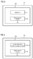
- FIG. 3 shows a first exemplary memory SP2 a bus device G7 a bus-oriented programmable electrical installation with loaded application A and operating system BS.
- the operating system BS comprises a communication stack CS for communication of the device G7, for example with other bus subscribers.
- the communication stack CS comprises the functionality required for sending and receiving data for a bus device.
- the representation according to FIG. 3 represents the initial scenario, with the operating system BS as the operating system to be exchanged.
- the application A and the operating system BS are active.
- FIG. 4 shows a second exemplary memory SP3 a bus device G8 a bus-oriented programmable electrical installation with loaded update application UP-A3 and the operating system BS.
- the update application UP-A3 includes a communication stack and a corresponding hardware adaptation for communication and flash access of the device G8.
- This update application UP-A3 is loaded to the position in the device where the "normal" application would also be.
- the update application UP-A3 assumes sole control of the device G8.
- the existing operating system BS is no longer addressed. This also includes that the interrupt vectors so initialized, that they all refer to the update application UP-A3.
- all individual data is stored so that the update application UP-A3 can access it while the operating system update is performed and this memory area is deleted or rewritten.
- the individual data include e.g. the individual address, serial number, manufacturing data of the device G8.
- the interrupt vectors are initialized to suit the new operating system and the G8 device is restarted with advantage. This will transfer control to the new operating system after the reboot.
- the individual data can be set in the new operating system at the end (before the restart) of the update application UP-A3 or the image for the update is patched with the previously read by the upload tool (eg ETS) data so that the Data already stored correctly in the operating system Image.
- the upload tool eg ETS
- the update application UP-A3 then copies the data to the correct position in memory SP3 (eg flash memory) before restarting. This is necessary to ensure that the time in which a power failure is a defective device causes as small as possible.
- the power supply for the copying of the block is ensured by the charging capacitor (electric capacitor) of the power supply.
- the new application can also be loaded into the device G8.
- the new operating system to be transferred can also be transmitted compressed or encrypted in this method.
- the update application UP-A3 also takes over the decryption or decompression in this case.
- the key for decompression can be negotiated at runtime between the update application UP-A3 and the tool (upload tool, for example ETS). Common compression (e.g., RLE) and encryption techniques (e.g., RSA) are useful.
- a malfunction for example, power failure
- the update application UP-A3 implements only the parts of the communication stack that are needed for identification (after a power failure) and upload.
- the old application is deactivated before carrying out the method.
- Providing the update application may e.g. by generating, generating, programming, or by providing from a program library.
- the update application can e.g. as "COTS" Software (Commercials Off The Shelf) by downloading (downloading) from the Internet.
- the update application may comprise the communication stack or means (e.g., corresponding program code) for managing the communication stack.
- the method can be carried out with hardware that is usually present in a bus-oriented programmable electrical installation (communication bus, bus devices, configuration devices (eg ETS) with appropriate software.
- a bus-oriented programmable electrical installation communication bus, bus devices, configuration devices (eg ETS) with appropriate software.
- the method is used in particular for KNX products (actuators, sensors, etc.).
- the method may be performed with hardware (communication bus, bus devices, configuration devices (e.g., ETS), commonly used in a bus-oriented programmable electrical installation, with appropriate software.
- hardware communication bus, bus devices, configuration devices (e.g., ETS), commonly used in a bus-oriented programmable electrical installation, with appropriate software.
- the method is used in particular for KNX products (actuators, sensors, etc.).
- the advantage of the present invention lies in particular in the separation of the update application and the new operating system.
- the update application is smaller, ie it requires little storage space.
- This separation makes it possible after negotiating a key to protect the data of the operating system during the transfer from unauthorized access.
- a standard update application can be developed which is easily adaptable to different hardware (eg different device types) and which can be used without change for different operating system updates on the same hardware.
- the same hardware in this sense means that only the hardware in the communication area must be identical. Everything else just needs to be initialized so that the hardware is in a safe state. It is thus possible to create a dedicated update application for an entire device family. (eg 2, 4, 8 or 12 channel binary actuators). This makes it easier to automatically create operating system updates in development, or it can directly use the data needed to manufacture the devices.
Landscapes
- Engineering & Computer Science (AREA)
- Software Systems (AREA)
- General Engineering & Computer Science (AREA)
- Theoretical Computer Science (AREA)
- Computer Security & Cryptography (AREA)
- Physics & Mathematics (AREA)
- General Physics & Mathematics (AREA)
- Stored Programmes (AREA)
Abstract
Description
- Die Erfindung betrifft ein Verfahren zur Durchführung eines Betriebssystem-Updates für ein Busgerät einer busorientierten programmierbaren Elektroinstallation. Weiterhin betrifft die Erfindung ein Busgerät, geeignet zur Durchführung eines Betriebssystem-Updates. Ferner betrifft die Erfindung ein Computerprogramm zur Durchführung eines Betriebssystem-Updates für ein Busgerät einer busorientierten programmierbaren Elektroinstallation und ein computerlesbares Medium, das auf einem Computer ausführbare Befehle aufweist zur Durchführung eines Betriebssystem-Updates für ein Busgerät einer busorientierten programmierbaren Elektroinstallation.
- Um in modernen Gebäuden bzw. Häusern eine einfache und komfortable Bedienung der verschiedenen Busgeräte zu ermöglichen, können diese über einen Installationsbus angesteuert werden. Ein solcher Installationsbus ist beispielsweise der europäische Installationsbus (EIB), der in dem KNX-Standard beschrieben ist.
- Eine Gebäudeinstallationseinrichtung ermöglicht es, einzelne Gebäudeinstallationen, wie beispielsweise eine Lampe oder einen Heizkörper, individuell gemäß einem vorgegebenen Betriebsplan zu steuern, indem an jeder Gebäudeinstallation ein Busgerät bereitgestellt wird, welches die jeweilige Gebäudeinstallation steuert, also beispielsweise automatisch eine Lampe an- und ausschaltet oder einen Thermostat eines Heizkörpers einstellt. Die Busgeräte können dabei untereinander und auch mit einem zentralen Konfigurationsgerät über einen Gebäudeinstallationsbus verbunden sein, so dass die Geräte gegenseitig Daten austauschen können und die Busgeräte zentral über das Konfigurationsgerät konfiguriert oder re-konfiguriert werden können. Die unter den Busgeräten ausgetauschten Daten können beispielsweise Sensordaten oder Steuerdaten sein.
- Das zugrundliegende Bussystem basiert darauf, dass jeder Busteilnehmer über einen eigenen Mikroprozessor verfügt und somit selbständig und unabhängig von einem zentralen Prozessor seine Daten verwaltet. Jedem Busteilnehmer ist hierzu ein Applikationsprogramm mit Kommunikationsobjekten und Parametern zugeordnet. Bei der Inbetriebsetzung eines derartigen Bussystems müssen die Kommunikationsbeziehungen der Busteilnehmer projektiert werden. Im Falle des KNX-Busses kommt hierbei häufig die Engineering Tool-Software (ETS) zum Einsatz. Hierbei handelt es sich um eine Software, die auf einem PC bzw. Laptop lauffähig ist und mit dem Bus verbunden wird. Einige mögliche Arten der Verbindungen sind RS232, USB, Funk oder Ethernet. Bei der ETS handelt es sich um ein datenbankbasiertes graphisches Werkzeug zur Projektierung einer busorientierten programmierbaren Elektroinstallation. In der ETS-Datenbank sind die Projektierungsdaten für jeden einzelnen Busteilnehmer bzw. jedes einzelne Applikationsprogramm gespeichert.
- Der Austausch von Applikationsprogrammen bei Busgeräten ist schon länger bekannt und wird von vielen Herstellern ermöglicht, auch insbesondere für Endkunden im Feld.
- Bisher ist es aber für Endkunden im Feld nicht möglich für ein Busgerät einer busorientierten programmierbaren Elektroinstallation (z.B. KNX-Bus) ein Betriebssystemupdate oder einen Betriebssystemtausch durchzuführen. Dafür muss der Kunde ein Busgerät ausbauen, einschicken und dann wieder einbauen. Dies ist umständlich, kosten- und zeitintensiv.
- In der deutschen Patentanmeldung (Anmeldekennzeichen
102015207900.7 , Anmeldetag 29.04.2015) der Anmelderin wird ein Verfahren für die Durchführung eines Betriebssystemupdates beschrieben, dieses Verfahren ist aber verhältnismässig speicherintensiv. - Es ist daher die Aufgabe der vorliegenden Erfindung, ein Speicherplatz effizientes Verfahren für die Durchführung von Betriebssystem-Updates für ein Busgerät einer busorientierten programmierbaren Elektroinstallation bereitzustellen.
- Die Aufgabe wird gelöst durch ein Verfahren zur Durchführung eines Betriebssystem-Updates für ein Busgerät einer busorientierten programmierbaren Elektroinstallation, wobei das Busgerät einen Prozessor (Mikrokontroller) und einen Speicher umfasst, das Verfahren umfasst die folgenden Schritte:
- Bereitstellen einer Update-Applikation, die die einen Kommunikationsstack und eine entsprechende Hardwareanpassung für Kommunikation und Flashzugriff des Gerätes umfasst;
- Laden der Update-Applikation in den Speicher, wobei nach dem erfolgten Laden die Update-Applikation die Kontrolle über das Busgerät übernimmt und das vorhandene Betriebssystem nicht mehr ansprechbar ist;
- Initialisieren der Interruptvektoren, damit diese auf die Update-Applikation verweisen;
- Durchführen des Betriebssystem-Update, wobei die individuellen Daten des Gerätes so abgelegt werden, dass die Update-Applikation während der Durchführung des Betriebssystem-Updates darauf zugreifen kann; und wobei während der Durchführung des Betriebssystem-Updates die Kommunikation des Busgerätes über die Update-Applikation erfolgt. Durch die Trennung von Update-Applikation und dem neuen Betriebssystem benötigt die Update-Applikation wenig Speicherplatz im Busgerät. Weithin ist der Entwicklungsaufwand für die Update-Applikation kleiner, da das Betriebssystem nicht extra in eine Applikation integriert werden muss. Es kann eine Standard-Update-Applikation entwickelt werden, die einfach an unterschiedliche Hardware anpassbar ist und die ohne Änderung für verschiedene Betriebssystemupdates auf gleicher Hardware verwendet werden kann. Mit Vorteil handelt es sich beim Busgerät um einen KNX-Busteilnehmer. Das Bereitstellen der Update-Applikation kann z.B. durch Erzeugen, Generieren, Programmieren erfolgen, oder durch Bereitstellung aus einer Programmbibliothek.
- Eine erste vorteilhafte Ausgestaltung der Erfindung liegt darin, dass nach der Durchführung des Betriebssystem-Updates die Interruptvektoren des Busgerätes für das neue Betriebssystem gesetzt werden. Nach Abschluss des Updates werden die Interruptvektoren so initialisiert, dass sie für das neue Betriebssystem passen. Mit Vorteil wird das Gerät nach der Initialisierung der Interruptvektoren neu gestartet.
- Eine weitere vorteilhafte Ausgestaltung der Erfindung liegt darin, dass nach der Durchführung des Betriebssystem-Updates die individuellen Daten des Busgerätes für das neue Betriebssystem gesetzt werden. Bei den individuellen Gerätedaten eines Busgerätes handelt es sich z.B. um die Seriennummer, das Fertigungsdatum, die Individuelle Adresse oder um Kalibrierdaten aus der Endprüfung.
- Eine weitere vorteilhafte Ausgestaltung der Erfindung liegt darin, dass nach einem Neustart des Busgerätes das neue Betriebssystem die Kontrolle über das Busgerät übernimmt. Nach erfolgtem Upload der Update-Applikation und einem Neustart übernimmt die Update-Applikation die alleinige Kontrolle über das Busgerät. Das vorhandene Betriebssystem wird nicht mehr angesprochen.
- Eine weitere vorteilhafte Ausgestaltung der Erfindung liegt darin, dass vor der Durchführung des Betriebssystem-Updates die alte bereits im Busgerät vorhandene Applikation deaktiviert wird. Durch die Deaktivierung der alten, bereits im Busgerät vorhandenen Applikation, wird sichergestellt, dass diese bei der Durchführung des Betriebssystem-Updates nicht stört.
- Eine weitere vorteilhafte Ausgestaltung der Erfindung liegt darin, dass nach Durchführung des Betriebssystem-Updates eine neue Applikation auf das Busgerät geladen wird. Dadurch dass unmittelbar nach der Durchführung des Betriebssystem-Updates eine neue Applikation auf das Busgerät geladen wird, wird die Umrüst- bzw. Aufrüstzeit für das Busgerät sehr niedrig gehalten.
- Eine weitere vorteilhafte Ausgestaltung der Erfindung liegt darin, dass das Laden der Update-Applikation und des neuen Betriebssystems über eine Busschnittstelle (KNX) des Busgerätes zur busorientierten programmierbaren Elektroinstallation erfolgt. Bei dieser Ausgestaltung ist kein externes Tool (als Upload-Tool) erforderlich, denn ein anderes Busgerät des Gebäudeautomatisierungssystems wird als Upload-Tool verwendet.
- Eine weitere vorteilhafte Ausgestaltung der Erfindung liegt darin, dass das Laden der Update-Applikation und des neuen Betriebssystems über eine externe Schnittstelle des Busgerätes erfolgt. Z.B. kann das Laden der Update-Applikation über eine USB-Schnittstelle des Busgerätes durch ein Konfigurationsgerät (z.B. ETS erfolgen). Dadurch wird beim Ladevorgang der Busverkehr (Traffic) nicht beeinträchtigt.
- Die Aufgabe wird weiterhin gelöst durch ein Computerprogramm zur Durchführung eines Betriebssystem-Updates für ein Busgerät einer busorientierten programmierbaren Elektroinstallation mit Instruktionen zur Ausführung des erfindungsgemässen Verfahrens. Dadurch kann ein Betriebssystem-Update computerunterstützt und effektiv erfolgen, z.B. durch einen Personal Computer (PC), insbesondere durch einen Endkunden im Feld.
- Die Aufgabe wird weiterhin gelöst durch ein computerlesbares Medium, das auf einem Computer ausführbare Befehle aufweist zur Durchführung eines Betriebssystem-Updates gemäss dem erfindungsgemässen Verfahren. Dadurch kann das Computerprogramm zur Durchführung eines Betriebssystem-Updates sehr leicht auf einem Computer (insbesondere bei einem Endkunden im Feld) implementiert bzw. installiert werden.
- Die Aufgabe wird weiterhin gelöst durch ein Busgerät einer busorientierten programmierbaren Elektroinstallation, geeignet zur Durchführung des erfindungsgemässen Verfahrens. Bei einem solchen Busgerät kann ein Endkunde im Feld ein Betriebssystem-Update durchführen. Ein Kunde braucht für ein Betriebssystem-Update das Busgerät nicht ausbauen, an den Hersteller oder Lieferanten einschicken, und dann wieder einbauen.
- Die Erfindung sowie vorteilhafte Ausführungen der vorliegenden Erfindung werden am Beispiel der nachfolgenden Figuren erläutert. Dabei zeigen:
- FIG 1
- eine erste beispielhafte Anordnung für ein Gebäudeautomatisierungssystem mit zwei beispielhaften Busgeräten,
- FIG 2
- eine zweite beispielhafte Anordnung für ein Gebäudeautomatisierungssystem mit mehreren beispielhaften Busteilnehmern,
- FIG 3
- einen ersten beispielhaften Speicher eines Busgerätes einer busorientierten programmierbaren Elektroinstallation mit geladener Applikation und Betriebssystem,
- FIG 4
- einen zweiten beispielhaften Speicher eines Busgerätes einer busorientierten programmierbaren Elektroinstallation mit geladener Update-Applikation und Betriebssystem,
- FIG 5
- ein erstes beispielhaftes Ablaufdiagramm für ein Verfahren zur Durchführung eines Betriebssystem-Updates für ein Busgerät einer busorientierten programmierbaren Elektroinstallation, und
- FIG 6
- ein zweites beispielhaftes Ablaufdiagramm für ein Verfahren zur Durchführung eines Betriebssystem-Updates für ein Busgerät einer busorientierten programmierbaren Elektroinstallation.
- Gebäudeinstallationen, insbesondere Elektroinstallationen zur Steuerung von Lichtquellen, Jalousien, Ventilatoren, Heizungen, Alarmanlagen etc. werden häufig unter Verwendung von standardisierter Bustechnik realisiert, z.B. mit einem KNX-Bussystem. Mit einem KNX-Bussystem werden in einem Gebäude Bedienelemente (Sensoren) und entsprechende Aktoren miteinander verbunden und angesteuert. Jeder Teilnehmer eines solchen Bussystems verfügt über einen eigenen Mikroprozessor und kann somit selbständig und unabhängig von einem zentralen Prozessor seine Daten verwalten. Jedem Busgerät wird hierzu ein Applikationsprogramm mit entsprechenden Kommunikationsobjekten und Parametern zugeordnet. Bei der Inbetriebnahme eines KNX-Bussystems (oder einem ähnlichen System) müssen die Kommunikationsbeziehungen und Parameter der Busgeräte projektiert werden. Für die Projektierung von KNX-Bussystemen wird üblicherweise die Engineering-Tool-Software (ETS) verwendet. Bei der ETS handelt es sich um ein datenbankbasiertes grafisches Werkzeug zur Projektierung von busorientierten programmierbaren Elektroinstallationen. Unter Verwendung einer Datenbank werden in der ETS die Projektierungsdaten, d. h. die Kommunikationsbeziehungen und die Geräteparameter, für jedes Busgerät bzw. jedes Applikationsprogramm separat erstellt und abschließend über eine Schnittstelle (z.B. USB Datenschnittstelle) in das Bussystem und deren Busgeräte übertragen bzw. eingespeist.
- Eine Gebäudeinstallationseinrichtung ermöglicht es, einzelne Gebäudeinstallationen, wie beispielsweise eine Lampe oder einen Heizkörper, individuell gemäß einem vorgegebenen Betriebsplan zu steuern, indem an jeder Gebäudeinstallation ein Busgerät bereitgestellt wird, welches die jeweilige Gebäudeinstallation steuert, also beispielsweise automatisch eine Lampe an- und ausschaltet oder einen Thermostat eines Heizkörpers einstellt. Die Busgeräte können dabei untereinander und auch mit einem zentralen Konfigurationsgerät über einen Gebäudeinstallationsbus verbunden sein, so dass die Geräte gegenseitig Daten austauschen können und die Busgeräte zentral über das Konfigurationsgerät konfiguriert oder re-konfiguriert werden können. Die unter den Busgeräten ausgetauschten Daten können beispielsweise Sensordaten oder Steuerdaten sein.
-
Figur 1 zeigt eine beispielhafte Anordnung für ein Gebäudeautomatisierungssystem GBS1 basierend auf einer busorientierten programmierbaren Elektroinstallation mit zwei beispielhaften Busgeräten G1, G2, die über einen Installationsbus B1, z.B. ein KNX-Bus, verbunden sind. Bei der Darstellung gemässFigur 1 handelt es sich nur um eine schematische Darstellung, wobei die Grössenproportionen der dargestellten Elemente nicht realitätsgetreu dargestellt sind. - Ein Busgerät G1, G2 weist in der Regel einen Prozessor MK als Steuereinheit auf, beispielsweise einen Mikrokontroller. Die Steuereinheit MK kann Steuerbefehle für die angeschlossene Gebäudeinstallation GBS1 erzeugen und/oder Sensordaten von der Gebäudeinstallation GBS1 auswerten. Um der Steuereinheit MK einen Datenaustausch mit dem Gebäudeinstallationsbus B1 zu ermöglichen, weist ein Busgerät G1, G2 in der Regel eine spezielle Anschlussschaltung als Busankoppler BK auf. Hierbei kann es sich beispielsweise um einen integrierten Schaltkreis (IC Integrated Circuit) handeln. Die Anschlussschaltung BK umfasst auch die elektrischen Anschlüsse zum Anschließen des Busgeräts G1, G2 an den Gebäudeinstallationsbus B1.
- Ein Prozessor MK als Steuereinheit eines Busgerätes G1 weist in der Regel folgende Speichertypen auf:
- einen RAM-Speicher (Random Access Memory) zum Speichern von Daten, die während des Betriebs anfallen;
- einen ROM-Speicher (Read Only Memory), in dem z.B. auch individuelle Gerätedaten abgelegt sein können;
- einen Flash-Speicher (z.B. EEPROM) für die persistente Speicherung der Applikationsprogramme und der dazugehörigen Projektierungsdaten, sowie des Betriebssystems. In einem Teil des Flash-Speichers können auch die individuellen Gerätedaten abgelegt sein.
- In der Darstellung gemäss
Figur 1 umfasst der Prozessor MK des Busgerätes G1 einen beispielhaften Flash-Speicher SP1, insbesondere geeignet zur Aufnahme des Betriebssystems und der Applikationen (Programme und die dazugehörigen Parametrierungen) für das Busgerät G1. - Mit Vorteil handelt es sich beim Busgerät G1 um einen Busteilnehmer (z.B. Aktor oder Sensor) einer busorientierten programmierbaren Elektroinstallation GBS1 (z.B. KNX-System), wobei das Busgerät G1 mindestens einen Prozessor (z.B. Mikrokontroller) MK und einen Speicher SP1 (z.B. einen persistenten Flash-Speicher) umfasst.
- Das Busgerät G1 ist dazu eingerichtet über eine Busschnittstelle BK (Busankoppler) oder über eine externe Schnittstelle SS1 (z.B. USB Schnittstelle) eine Update-Applikation UP-A1, die einen Kommunikationsstack und eine entsprechende Hardwareanpassung für Kommunikation und Flashzugriff des Busgerätes G1 umfasst, in den Speicher SP1 zu laden. Über die externe Schnittstelle SS1 kann die Update-Applikation UP-AL z.B. von einem Konfigurationsgerät (Upload-Tool, z. B. ETS (Engineering-Tool-Software)) auf das Gerät G1 übertragen werden.
-
Figur 2 zeigt eine zweite beispielhafte Anordnung für ein Gebäudeautomatisierungssystem GBS2 mit mehreren beispielhaften Busteilnehmern G3 - G6, und einer optionalen Leitstelle LS (z.B. eine Gebäude-Management-Station), die über einen Gebäudeinstallationsbus B2 (z.B. KNX-Bus) verbunden sind. - In der Darstellung gemäss
Figur 2 erfolgt ein Betriebssystemupdate für das Busgerät G3 durch ein Laden der UpdateApplikation UP-A2, die einen Kommunikationsstack und eine entsprechende Hardwareanpassung für Kommunikation und Flashzugriff des Gerätes G3 umfasst, über die externe Schnittstelle SS2, z.B. eine USB-Schnittstelle. Das Busgerät G3 ist dazu eingerichtet, dass die Update-Applikation UP-A2 in den Speicher in den Speicher des Gerätes G3 geladen wird, wobei nach dem erfolgten Laden die Update-Applikation UP-A2 die Kontrolle über das Busgerät G3 übernimmt und das vorhandene Betriebssystem nicht mehr ansprechbar ist. Weiterhin erfolgt ein Initialisieren der Interruptvektoren, damit diese auf die UpdateApplikation UP-A2 verweisen. Danach erfolgt das Durchführen des Betriebssystem-Updates, wobei die individuellen Daten des Gerätes so abgelegt werden, dass die Update-Applikation UP-A2 während der Durchführung des Betriebssystem-Updates darauf zugreifen kann, und wobei während der Durchführung des Betriebssystem-Updates die Kommunikation des Busgerätes über die Update-Applikation UP-A2 erfolgt. - In der Darstellung gemäss
Figur 2 erfolgt das Laden der Update-Applikation UP-A2 und des neuen Betriebssystems über die Kommunikationsverbindung KV (z.B. ein USB-Übertragungskabel) und über die Schnittstelle SS2 auf das Gerät G3. - Beim Konfigurationsgerät KG handelt es sich bei KNX-Systemen mit Vorteil um eine ETS (Engineering-Tool-Software).
-
Figur 3 zeigt einen ersten beispielhaften Speicher SP2 eines Busgerätes G7 einer busorientierten programmierbaren Elektroinstallation mit geladener Applikation A und Betriebssystem BS. Das Betriebssystem BS umfasst einen Kommunikations-Stack CS zur Kommunikation des Gerätes G7 z.B. mit anderen Busteilnehmern. Der Kommunikations-Stack CS umfasst die zum Senden und Empfangen von Daten benötigte Funktionalität für ein Busgerät. - Die Darstellung gemäss
Figur 3 stellt das Ausgangsszenario dar, mit dem Betriebssystem BS als auszutauschendem Betriebssystem. InFigur 3 sind sowohl die Applikation A als auch das Betriebssystem BS aktiv. -
Figur 4 zeigt einen zweiten beispielhaften Speicher SP3 eines Busgerätes G8 einer busorientierten programmierbaren Elektroinstallation mit geladener Update-Applikation UP-A3 und dem Betriebssystem BS. Die Update-Applikation UP-A3 umfasst einen Kommunikationsstack und eine entsprechende Hardwareanpassung für Kommunikation und Flashzugriff des Gerätes G8. - Diese Update-Applikation UP-A3 wird an die Position in das Gerät geladen an der die "normale" Applikation auch wäre.
- Nach erfolgtem Upload der Update-Applikation UP-A3 übernimmt die Updateapplikation UP-A3 die alleinige Kontrolle über das Gerät G8. Das vorhandene Betriebssystem BS wird nicht mehr angesprochen. Dazu gehört auch, dass die Interruptvektoren so initialisiert werden, dass sie alle auf die Update-Applikation UP-A3 verweisen.
- Mit Vorteil werden alle individuellen Daten werden so abgelegt, dass die Update-Applikation UP-A3 darauf zugreifen kann, während das Betriebssystem Update durchgeführt wird und dieser Speicherbereich gelöscht bzw. neu beschrieben wird. Zu den individuellen Daten gehören z.B. die Individuelle Adresse, Seriennummer, Fertigungsdaten des Gerätes G8.
- Während des Betriebssystemupdates (bzw. Upload des neuen Betriebssystems) läuft die Kommunikation mit dem Gerät G8 über die Update-Applikation UP-A3 und der Speicherplatz für das Betriebssystem kann vom Updatetool (z.B. ETS bei KNX-Systemen) direkt beschrieben werden.
- Nach Abschluss des Upload des neuen Betriebssystems werden die Interruptvektoren so initialisiert, dass sie für das neue Betriebssystem passen und das Gerät G8 wird mit Vorteil neu gestartet. Dadurch geht die Kontrolle nach dem Neustart auf das neue Betriebssystem über.
- Die Individuellen Daten können am Schluss (vor dem Neustart) von der Update-Applikation UP-A3 wieder im neuen Betriebssystem gesetzt werden oder das Image für das Update wird mit den vorher vom Upload-Tool (z.B. ETS) ausgelesenen Daten so gepatcht, dass die Daten schon korrekt im Betriebssystem Image abgelegt sind.
- Unter Umständen ist es erforderlich den Block mit den Interruptvektoren beim Upload an eine andere Stelle zu schreiben. Die Update-Applikation UP-A3 kopiert die Daten dann vor dem Neustart an die korrekte Position im Speicher SP3 (z.B. Flash-Speicher). Dies ist erforderlich um sicherzustellen, dass die Zeit in der ein Netzausfall ein defektes Gerät hervorruft möglichst klein ist. Die Spannungsversorgung für das Umkopieren des Blocks wird von dem Ladeelko (Elektrokondensator) der Spannungsversorgung sichergestellt.
- Als nächster Schritt kann die neue Applikation auch in das Gerät G8 geladen werden.
- Das zu übertragene neue Betriebssystem kann bei diesem Verfahren auch komprimiert oder verschlüsselt übertragen werden. Die Update-Applikation UP-A3 übernimmt in diesem Fall auch die Entschlüsselung bzw. Dekomprimierung. Der Schlüssel für die Dekomprimierung kann zwischen der Update-Applikation UP-A3 und dem Tool (Uploadtool, z.B. ETS) zur Laufzeit ausgehandelt werden. Gängige Kompromier- (z.B. RLE) bzw. Verschlüsselungsverfahren (z.B. RSA) sind dabei verwendbar.
- Dadurch kann ein Ausspähen der Betriebssystemdaten (Programmcode) während der Übertragung verhindert werden. Durch die dauerhafte Speicherung der individuellen Daten in der UpdateApplikation UP-A3 kann dieses Verfahren durch eine Störung (z.B. Netzausfall) nicht so beeinflusst oder gestört werden, dass das Gerät G8 nicht mehr anläuft, da alle relevanten Daten während des Updates weiter zur Verfügung stehen. Falls also ein Netzausfall eintritt, kann die Gerät ganz normal wieder anlaufen (mit der Update-Applikation UP-A3) und das Update weiter durchgeführt werden.
- Mit Vorteil implementiert die Update-Applikation UP-A3 nur die Teile des Kommunikations-Stacks, die für die Identifizierung (nach einem Netzausfall) und den Upload benötigt werden.
-
Figur 5 zeigt ein erstes beispielhaftes Ablaufdiagramm für ein Verfahren zur Durchführung eines Betriebssystem-Updates für ein Busgerät einer busorientierten programmierbaren Elektroinstallation, wobei das Busgerät einen Prozessor (Mikrokontroller) und einen Speicher umfasst, das Verfahren umfasst die folgenden Schritte: - (VS1) Bereitstellen einer Update-Applikation, die die einen Kommunikationsstack und eine entsprechende Hardwareanpassung für Kommunikation und Flashzugriff des Gerätes umfasst;
- (VS2) Laden der Update-Applikation in den Speicher, wobei nach dem erfolgten Laden die Update-Applikation die Kontrolle über das Busgerät übernimmt und das vorhandene Betriebssystem nicht mehr ansprechbar ist;
- (VS3) Initialisieren der Interruptvektoren, damit diese auf die Update-Applikation verweisen;
- (VS4) Durchführen des Betriebssystem-Update, wobei die individuellen Daten des Gerätes so abgelegt werden, dass die Update-Applikation während der Durchführung des Betriebssystem-Updates darauf zugreifen kann; und wobei während der Durchführung des Betriebssystem-Updates die Kommunikation des Busgerätes über die Update-Applikation erfolgt.
- Mit Vorteil wird vor der Durchführung des Verfahrens die alte Applikation deaktiviert. Das Bereitstellen der UpdateApplikation kann z.B. durch Erzeugen, Generieren, Programmieren erfolgen, oder durch Bereitstellung aus einer Programmbibliothek. Die Update-Applikation kann z.B. als "COTS" Software (Commercials Off The Shelf) durch einen Download (Herunterladen) vom Internet bezogen werden. Die Update-Applikation kann dabei den Kommunikations-Stack umfassen oder Mittel (z.B. entsprechenden Programmcode) zum Verwalten des KommunikationsStacks.
- Das Verfahren kann mit bei einer busorientierten programmierbaren Elektroinstallation üblicherweise vorhandenen Hardware (Kommunikationsbus, Busgeräte, Konfigurationsgeräte (z.B. ETS) mit entsprechender Software durchgeführt werden.
- Mit Vorteil wird das Verfahren insbesondere für KNX-Produkte (Aktoren, Sensoren, etc.) verwendet.
-
Figur 6 zeigt ein zweites beispielhaftes Ablaufdiagramm für zur Durchführung des erfindungsgemässen Betriebssystem-Updates für ein Busgerät einer busorientierten programmierbaren Elektroinstallation, wobei das Busgerät einen Prozessor (Mikrokontroller) und einen Speicher umfasst, das Verfahren umfasst die folgenden Schritte: - (VS1') alte Applikation deaktivieren (optional);
- (VS2') Updateapplikation in das Gerät laden;
- (VS3') Die Updateapplikation übernimmt die Kontrolle und setzt die Interruptvektoren um und merkt sich die individuellen Daten des Gerätes;
- (VS4') altes Betriebssystem wird durch ein neues Betriebssystem ersetzt;
- (VS5') Die Interruptvektoren und individuellen werden für das neue Betriebssystem gesetzt;
- (VS6') Nach einem Neustart übernimmt das neue Betriebssystem die Kontrolle;
- (VS7') Die neue Applikation wird in das Gerät geladen (optional).
- Das Verfahren kann mit bei einer busorientierten programmierbaren Elektroinstallation üblicherweise vorhandenen Hardware (Kommunikationsbus, Busgeräte, Konfigurationsgeräte (z.B. ETS) mit entsprechender Software durchgeführt werden.
- Mit Vorteil wird das Verfahren insbesondere für KNX-Produkte (Aktoren, Sensoren, etc.) verwendet.
- Der Vorteil der vorliegenden Erfindung liegt insbesondere in der Trennung der Updateapplikation und dem neuen Betriebssystem. Dadurch ist die Updateapplikation kleiner, d.h. sie benötigt wenig Speicherplatz. Durch diese Trennung ist es nach Aushandlung eines Schlüssels möglich die Daten des Betriebssystems während der Übertragung vor unbefugtem Zugriff zu schützen.
- Weiterhin ist der Entwicklungsaufwand kleiner, da das Betriebssystem nicht extra in eine Applikation integriert werden muss. Es kann eine Standard-Updateapplikation entwikkelt werden, die einfach an unterschiedliche Hardware (z.B. unterschiedliche Gerätetypen) anpassbar ist und die ohne Änderung für verschiedene Betriebssystemupdates auf gleicher Hardware verwendet werden kann. Gleiche Hardware bedeutet in diesem Sinne, dass nur die Hardware im Kommunikationsbereich identisch sein muss. Alles andere muss nur so initialisiert werden, dass sich die Hardware in einem sicheren Zustand befindet. Es ist damit möglich eine dedizierte Updateapplikation für eine ganze Gerätefamilie zu erstellen. (z.B. Binäraktoren mit 2, 4, 8 oder 12 Kanälen). Dadurch ist es einfacher Betriebssystemupdates in der Entwicklung automatisiert zu erstellen bzw. es können direkt die Daten verwendet werden, die für die Fertigung der Geräte benötigt werden.
-
- G1 - G8
- Busgerät
- B1 - B2
- Bus
- SP1 - SP3
- Speicher
- A
- Applikation
- UP-A1 - UP-A3
- Update-Applikation
- BS
- Betriebssystem
- CS
- Kommunikations-Stack
- BSA
- Altes Betriebssystem
- GBS1, GBS2
- Gebäudeautomatisierungssystem
- BK
- Busankoppler
- SS1, SS2
- Schnittstelle
- MK
- Prozessor
- LS
- Leitsystem
- KG
- Konfigurationsgerät
- KV
- Kommunikationsverbindung
- VS1 - VS4, VS1' - VS7'
- Verfahrensschritt
Claims (11)
- Verfahren zur Durchführung eines Betriebssystem-Updates für ein Busgerät (G1 - G8) einer busorientierten programmierbaren Elektroinstallation (GBS1, GBS2), wobei das Busgerät (G1 - G8) einen Prozessor (MK) und einen Speicher (SP1 - SP3) umfasst, das Verfahren umfasst die folgenden Schritte:(VS1) Bereitstellen einer Update-Applikation (UP-A1 - UP-A3), die die einen Kommunikationsstack (CS) und eine entsprechende Hardwareanpassung für Kommunikation und Flashzugriff des Gerätes (G1 - G8) umfasst;Laden der Update-Applikation (UP-A1 - UP-A3) in den Speicher, wobei nach dem erfolgten Laden die Update-Applikation (UP-A1 - UP-A3) die Kontrolle über das Busgerät (G1 - G8) übernimmt und das vorhandene Betriebssystem (BS) nicht mehr ansprechbar ist;Initialisieren der Interruptvektoren, damit diese auf die Update-Applikation (UP-A1 - UP-A3) verweisen;Durchführen des Betriebssystem-Update, wobei die individuellen Daten des Gerätes (G1 - G8) so abgelegt werden, dass die Update-Applikation (UP-A1 - UP-A3) während der Durchführung des Betriebssystem-Updates darauf zugreifen kann; und wobei während der Durchführung des Betriebssystem-Updates die Kommunikation des Busgerätes (G1 - G8) über die Update-Applikation (UP-A1 - UP-A3) erfolgt.
- Verfahren nach Anspruch 1, wobei nach der Durchführung des Betriebssystem-Updates die Interruptvektoren des Busgerätes (G1 - G8) für das neue Betriebssystem gesetzt werden.
- Verfahren nach einem der vorstehenden Ansprüche, wobei nach der Durchführung des Betriebssystem-Updates die individuellen Daten des Busgerätes (G1 - G8) für das neue Betriebssystem gesetzt werden.
- Verfahren nach einem der vorstehenden Ansprüche, wobei nach einem Neustart des Busgerätes (G1 - G8) das neue Betriebssystem die Kontrolle über das Busgerät (G1 - G8) übernimmt.
- Verfahren nach einem der vorstehenden Ansprüche, wobei vor der Durchführung des Betriebssystem-Updates die alte bereits im Busgerät (G1 - G8) vorhandene Applikation deaktiviert wird.
- Verfahren nach einem der vorstehenden Ansprüche, wobei nach Durchführung des Betriebssystem-Updates eine neue Applikation auf das Busgerät (G1 - G8) geladen wird.
- Verfahren nach einem der vorstehenden Ansprüche, wobei das Laden der Update-Applikation (UP-A1 - UP-A3) und des neuen Betriebssystems über eine Busschnittstelle (KNX) des Busgerätes (G1 - G8) zur busorientierten programmierbaren Elektroinstallation (GBS1, GBS2) erfolgt.
- Verfahren nach einem der vorstehenden Ansprüche, wobei das Laden der Update-Applikation (UP-A1 - UP-A3) und des neuen Betriebssystems über eine externe Schnittstelle des Busgerätes (G1 - G8) erfolgt.
- Computerprogramm zur Durchführung eines Betriebssystem-Updates für ein Busgerät (G1 - G8) einer busorientierten programmierbaren Elektroinstallation (GBS1, GBS2) mit Instruktionen zur Ausführung des Verfahrens nach einem der Patentansprüche 1 bis 8.
- Computerlesbares Medium, das auf einem Computer ausführbare Befehle aufweist zur Durchführung eines Betriebssystem-Updates gemäss eines Verfahren nach einem der Patentansprüche 1 bis 8 für ein Busgerät (G1 - G8) einer busorientierten programmierbaren Elektroinstallation (GBS1, GBS2).
- Busgerät (G1 - G8) einer busorientierten programmierbaren Elektroinstallation (GBS1, GBS2), geeignet zur Durchführung eines Verfahrens nach einem der Ansprüche 1 bis 8.
Applications Claiming Priority (1)
| Application Number | Priority Date | Filing Date | Title |
|---|---|---|---|
| DE102015213138.6A DE102015213138A1 (de) | 2015-07-14 | 2015-07-14 | Verfahren zur Durchführung eines Betriebssystem-Updates |
Publications (2)
| Publication Number | Publication Date |
|---|---|
| EP3118739A1 true EP3118739A1 (de) | 2017-01-18 |
| EP3118739B1 EP3118739B1 (de) | 2020-01-29 |
Family
ID=56263540
Family Applications (1)
| Application Number | Title | Priority Date | Filing Date |
|---|---|---|---|
| EP16175806.5A Active EP3118739B1 (de) | 2015-07-14 | 2016-06-22 | Verfahren zur durchführung eines betriebssystem-updates |
Country Status (3)
| Country | Link |
|---|---|
| EP (1) | EP3118739B1 (de) |
| DE (1) | DE102015213138A1 (de) |
| ES (1) | ES2779321T3 (de) |
Cited By (1)
| Publication number | Priority date | Publication date | Assignee | Title |
|---|---|---|---|---|
| CN114879988A (zh) * | 2022-04-20 | 2022-08-09 | 宁波天擎航天科技有限公司 | 一种在线升级方法、装置、计算机设备及存储介质 |
Citations (1)
| Publication number | Priority date | Publication date | Assignee | Title |
|---|---|---|---|---|
| EP0947920A2 (de) * | 1998-03-31 | 1999-10-06 | SANYO ELECTRIC Co., Ltd. | Vorrichtung und Verfahren zur Änderung eines Programmes in einem Rechnersystem |
Family Cites Families (3)
| Publication number | Priority date | Publication date | Assignee | Title |
|---|---|---|---|---|
| JP3727485B2 (ja) * | 1999-04-02 | 2005-12-14 | シャープ株式会社 | 不揮発性メモリ内蔵マイクロコンピュータ |
| US7093244B2 (en) * | 2001-04-18 | 2006-08-15 | Domosys Corporation | Method of remotely upgrading firmware in field-deployed devices |
| DE102015207900B4 (de) | 2015-04-29 | 2022-01-20 | Siemens Schweiz Ag | Verfahren zur Durchführung eines Betriebssystem-Updates |
-
2015
- 2015-07-14 DE DE102015213138.6A patent/DE102015213138A1/de not_active Withdrawn
-
2016
- 2016-06-22 ES ES16175806T patent/ES2779321T3/es active Active
- 2016-06-22 EP EP16175806.5A patent/EP3118739B1/de active Active
Patent Citations (1)
| Publication number | Priority date | Publication date | Assignee | Title |
|---|---|---|---|---|
| EP0947920A2 (de) * | 1998-03-31 | 1999-10-06 | SANYO ELECTRIC Co., Ltd. | Vorrichtung und Verfahren zur Änderung eines Programmes in einem Rechnersystem |
Cited By (1)
| Publication number | Priority date | Publication date | Assignee | Title |
|---|---|---|---|---|
| CN114879988A (zh) * | 2022-04-20 | 2022-08-09 | 宁波天擎航天科技有限公司 | 一种在线升级方法、装置、计算机设备及存储介质 |
Also Published As
| Publication number | Publication date |
|---|---|
| EP3118739B1 (de) | 2020-01-29 |
| ES2779321T3 (es) | 2020-08-14 |
| DE102015213138A1 (de) | 2017-01-19 |
Similar Documents
| Publication | Publication Date | Title |
|---|---|---|
| DE102015112040A1 (de) | Verfahren und System zur Firmware-Aktualisierung einer Steuereinrichtung zur Prozesssteuerung | |
| EP2591404A1 (de) | Verfahren zur konfigurierung einer steuerungseinrichtung | |
| WO2017008953A1 (de) | Verfahren und anordnung zum sicheren austausch von konfigurationsdaten einer vorrichtung | |
| DE112016002236B4 (de) | Kommunikationseinrichtung und kommunikationseinschränkungsprogramm | |
| EP2595016A1 (de) | Verfahren, Computerprogramm, computerlesbares Medium und Recheneinheit zur Bedienung von Feldgeräten | |
| WO2006069762A1 (de) | Verfahren zur konfiguration von feldgeräten | |
| EP3923095A1 (de) | Konfigurationsvorrichtung, aktualisierungsserver und verfahren für eine softwareaktualisierung einer technischen anlage | |
| EP4160390A1 (de) | Verfahren und anordnung zur inbetriebnahme einer aktualisierten anwendung für eine industrielle automatisierungsanordnung | |
| DE102012217312B4 (de) | Verfahren und System zur Aktualisierung von Code in Verarbeitungssystemen | |
| DE102012205709A1 (de) | Verfahren zum Betreiben eines elektrischen Antriebssystems und Antriebssystem | |
| EP3118739B1 (de) | Verfahren zur durchführung eines betriebssystem-updates | |
| DE102016123599A1 (de) | Robotersteuerung mit Funktion zur Kommunikation mit einer speicherprogrammierbaren Steuerung und Kommunikationssystem | |
| DE102015115855A1 (de) | System und Verfahren zur Verteilung und/oder Aktualisierung von Software in vernetzten Steuereinrichtungen eines Fahrzeugs | |
| EP2480940B1 (de) | Verfahren zum bereitstellen von sicherheitsfunktionen | |
| EP3125053A1 (de) | Verfahren und peripheriebaugruppe zur übertragung von hart-variablen sowie cpu-einheit zum lesen der hart-variablen | |
| DE102015207900B4 (de) | Verfahren zur Durchführung eines Betriebssystem-Updates | |
| DE102021101101A1 (de) | Adapter und Verfahren zum Beeinflussen oder Diagnostizieren eines Geräts | |
| DE102009051546A1 (de) | Vorrichtung mit einer Vielzahl von Steuergeräten für Fluid-Regelkreise | |
| EP2394232A2 (de) | Vorrichtung und verfahren zum verhindern von unautorisierter verwendung und/oder manipulation von software | |
| DE102022104113A1 (de) | Verfahren zum Bereitstellen eines Datenzugriffs auf eine technische Einrichtung und technische Einrichtung | |
| DE102016204395B4 (de) | Toolfreier Gerätetausch von Busgeräten | |
| EP3623955A1 (de) | Verfahren zum erzeugen von identifikatoren für informationseinheiten in einem verteilten system | |
| DE102013200322B3 (de) | Verfahren zum Betreiben eines Gebäudeinstallationssystems | |
| DE102013103858B4 (de) | Fencing –Vorrichtung zur Integration in einen Knoten eines Computer-Clusters | |
| EP3208982B1 (de) | Router mit separater schnittstelle zur konfiguration des routers sowie verfahren zur konfiguration eines routers |
Legal Events
| Date | Code | Title | Description |
|---|---|---|---|
| PUAI | Public reference made under article 153(3) epc to a published international application that has entered the european phase |
Free format text: ORIGINAL CODE: 0009012 |
|
| STAA | Information on the status of an ep patent application or granted ep patent |
Free format text: STATUS: THE APPLICATION HAS BEEN PUBLISHED |
|
| AK | Designated contracting states |
Kind code of ref document: A1 Designated state(s): AL AT BE BG CH CY CZ DE DK EE ES FI FR GB GR HR HU IE IS IT LI LT LU LV MC MK MT NL NO PL PT RO RS SE SI SK SM TR |
|
| AX | Request for extension of the european patent |
Extension state: BA ME |
|
| STAA | Information on the status of an ep patent application or granted ep patent |
Free format text: STATUS: REQUEST FOR EXAMINATION WAS MADE |
|
| 17P | Request for examination filed |
Effective date: 20170717 |
|
| RBV | Designated contracting states (corrected) |
Designated state(s): AL AT BE BG CH CY CZ DE DK EE ES FI FR GB GR HR HU IE IS IT LI LT LU LV MC MK MT NL NO PL PT RO RS SE SI SK SM TR |
|
| STAA | Information on the status of an ep patent application or granted ep patent |
Free format text: STATUS: EXAMINATION IS IN PROGRESS |
|
| 17Q | First examination report despatched |
Effective date: 20170904 |
|
| REG | Reference to a national code |
Ref country code: DE Ref legal event code: R079 Ref document number: 502016008506 Country of ref document: DE Free format text: PREVIOUS MAIN CLASS: G06F0009445000 Ipc: G06F0008650000 |
|
| RIC1 | Information provided on ipc code assigned before grant |
Ipc: G06F 9/445 20180101ALI20190731BHEP Ipc: G06F 8/65 20180101AFI20190731BHEP |
|
| GRAP | Despatch of communication of intention to grant a patent |
Free format text: ORIGINAL CODE: EPIDOSNIGR1 |
|
| STAA | Information on the status of an ep patent application or granted ep patent |
Free format text: STATUS: GRANT OF PATENT IS INTENDED |
|
| INTG | Intention to grant announced |
Effective date: 20191007 |
|
| GRAS | Grant fee paid |
Free format text: ORIGINAL CODE: EPIDOSNIGR3 |
|
| GRAA | (expected) grant |
Free format text: ORIGINAL CODE: 0009210 |
|
| STAA | Information on the status of an ep patent application or granted ep patent |
Free format text: STATUS: THE PATENT HAS BEEN GRANTED |
|
| AK | Designated contracting states |
Kind code of ref document: B1 Designated state(s): AL AT BE BG CH CY CZ DE DK EE ES FI FR GB GR HR HU IE IS IT LI LT LU LV MC MK MT NL NO PL PT RO RS SE SI SK SM TR |
|
| REG | Reference to a national code |
Ref country code: GB Ref legal event code: FG4D Free format text: NOT ENGLISH |
|
| REG | Reference to a national code |
Ref country code: CH Ref legal event code: EP |
|
| REG | Reference to a national code |
Ref country code: AT Ref legal event code: REF Ref document number: 1228945 Country of ref document: AT Kind code of ref document: T Effective date: 20200215 |
|
| REG | Reference to a national code |
Ref country code: IE Ref legal event code: FG4D Free format text: LANGUAGE OF EP DOCUMENT: GERMAN |
|
| REG | Reference to a national code |
Ref country code: DE Ref legal event code: R096 Ref document number: 502016008506 Country of ref document: DE |
|
| REG | Reference to a national code |
Ref country code: CH Ref legal event code: NV Representative=s name: SIEMENS SCHWEIZ AG, CH |
|
| REG | Reference to a national code |
Ref country code: NL Ref legal event code: FP |
|
| PG25 | Lapsed in a contracting state [announced via postgrant information from national office to epo] |
Ref country code: PT Free format text: LAPSE BECAUSE OF FAILURE TO SUBMIT A TRANSLATION OF THE DESCRIPTION OR TO PAY THE FEE WITHIN THE PRESCRIBED TIME-LIMIT Effective date: 20200621 Ref country code: RS Free format text: LAPSE BECAUSE OF FAILURE TO SUBMIT A TRANSLATION OF THE DESCRIPTION OR TO PAY THE FEE WITHIN THE PRESCRIBED TIME-LIMIT Effective date: 20200129 Ref country code: FI Free format text: LAPSE BECAUSE OF FAILURE TO SUBMIT A TRANSLATION OF THE DESCRIPTION OR TO PAY THE FEE WITHIN THE PRESCRIBED TIME-LIMIT Effective date: 20200129 Ref country code: NO Free format text: LAPSE BECAUSE OF FAILURE TO SUBMIT A TRANSLATION OF THE DESCRIPTION OR TO PAY THE FEE WITHIN THE PRESCRIBED TIME-LIMIT Effective date: 20200429 |
|
| REG | Reference to a national code |
Ref country code: LT Ref legal event code: MG4D |
|
| REG | Reference to a national code |
Ref country code: ES Ref legal event code: FG2A Ref document number: 2779321 Country of ref document: ES Kind code of ref document: T3 Effective date: 20200814 |
|
| PG25 | Lapsed in a contracting state [announced via postgrant information from national office to epo] |
Ref country code: GR Free format text: LAPSE BECAUSE OF FAILURE TO SUBMIT A TRANSLATION OF THE DESCRIPTION OR TO PAY THE FEE WITHIN THE PRESCRIBED TIME-LIMIT Effective date: 20200430 Ref country code: HR Free format text: LAPSE BECAUSE OF FAILURE TO SUBMIT A TRANSLATION OF THE DESCRIPTION OR TO PAY THE FEE WITHIN THE PRESCRIBED TIME-LIMIT Effective date: 20200129 Ref country code: BG Free format text: LAPSE BECAUSE OF FAILURE TO SUBMIT A TRANSLATION OF THE DESCRIPTION OR TO PAY THE FEE WITHIN THE PRESCRIBED TIME-LIMIT Effective date: 20200429 Ref country code: IS Free format text: LAPSE BECAUSE OF FAILURE TO SUBMIT A TRANSLATION OF THE DESCRIPTION OR TO PAY THE FEE WITHIN THE PRESCRIBED TIME-LIMIT Effective date: 20200529 Ref country code: LV Free format text: LAPSE BECAUSE OF FAILURE TO SUBMIT A TRANSLATION OF THE DESCRIPTION OR TO PAY THE FEE WITHIN THE PRESCRIBED TIME-LIMIT Effective date: 20200129 Ref country code: SE Free format text: LAPSE BECAUSE OF FAILURE TO SUBMIT A TRANSLATION OF THE DESCRIPTION OR TO PAY THE FEE WITHIN THE PRESCRIBED TIME-LIMIT Effective date: 20200129 |
|
| PG25 | Lapsed in a contracting state [announced via postgrant information from national office to epo] |
Ref country code: LT Free format text: LAPSE BECAUSE OF FAILURE TO SUBMIT A TRANSLATION OF THE DESCRIPTION OR TO PAY THE FEE WITHIN THE PRESCRIBED TIME-LIMIT Effective date: 20200129 Ref country code: DK Free format text: LAPSE BECAUSE OF FAILURE TO SUBMIT A TRANSLATION OF THE DESCRIPTION OR TO PAY THE FEE WITHIN THE PRESCRIBED TIME-LIMIT Effective date: 20200129 Ref country code: EE Free format text: LAPSE BECAUSE OF FAILURE TO SUBMIT A TRANSLATION OF THE DESCRIPTION OR TO PAY THE FEE WITHIN THE PRESCRIBED TIME-LIMIT Effective date: 20200129 Ref country code: SM Free format text: LAPSE BECAUSE OF FAILURE TO SUBMIT A TRANSLATION OF THE DESCRIPTION OR TO PAY THE FEE WITHIN THE PRESCRIBED TIME-LIMIT Effective date: 20200129 Ref country code: RO Free format text: LAPSE BECAUSE OF FAILURE TO SUBMIT A TRANSLATION OF THE DESCRIPTION OR TO PAY THE FEE WITHIN THE PRESCRIBED TIME-LIMIT Effective date: 20200129 Ref country code: CZ Free format text: LAPSE BECAUSE OF FAILURE TO SUBMIT A TRANSLATION OF THE DESCRIPTION OR TO PAY THE FEE WITHIN THE PRESCRIBED TIME-LIMIT Effective date: 20200129 Ref country code: SK Free format text: LAPSE BECAUSE OF FAILURE TO SUBMIT A TRANSLATION OF THE DESCRIPTION OR TO PAY THE FEE WITHIN THE PRESCRIBED TIME-LIMIT Effective date: 20200129 |
|
| REG | Reference to a national code |
Ref country code: DE Ref legal event code: R097 Ref document number: 502016008506 Country of ref document: DE |
|
| PLBE | No opposition filed within time limit |
Free format text: ORIGINAL CODE: 0009261 |
|
| STAA | Information on the status of an ep patent application or granted ep patent |
Free format text: STATUS: NO OPPOSITION FILED WITHIN TIME LIMIT |
|
| 26N | No opposition filed |
Effective date: 20201030 |
|
| PG25 | Lapsed in a contracting state [announced via postgrant information from national office to epo] |
Ref country code: MC Free format text: LAPSE BECAUSE OF FAILURE TO SUBMIT A TRANSLATION OF THE DESCRIPTION OR TO PAY THE FEE WITHIN THE PRESCRIBED TIME-LIMIT Effective date: 20200129 |
|
| PG25 | Lapsed in a contracting state [announced via postgrant information from national office to epo] |
Ref country code: SI Free format text: LAPSE BECAUSE OF FAILURE TO SUBMIT A TRANSLATION OF THE DESCRIPTION OR TO PAY THE FEE WITHIN THE PRESCRIBED TIME-LIMIT Effective date: 20200129 Ref country code: PL Free format text: LAPSE BECAUSE OF FAILURE TO SUBMIT A TRANSLATION OF THE DESCRIPTION OR TO PAY THE FEE WITHIN THE PRESCRIBED TIME-LIMIT Effective date: 20200129 |
|
| PG25 | Lapsed in a contracting state [announced via postgrant information from national office to epo] |
Ref country code: LU Free format text: LAPSE BECAUSE OF NON-PAYMENT OF DUE FEES Effective date: 20200622 |
|
| REG | Reference to a national code |
Ref country code: BE Ref legal event code: MM Effective date: 20200630 |
|
| PG25 | Lapsed in a contracting state [announced via postgrant information from national office to epo] |
Ref country code: IE Free format text: LAPSE BECAUSE OF NON-PAYMENT OF DUE FEES Effective date: 20200622 |
|
| PG25 | Lapsed in a contracting state [announced via postgrant information from national office to epo] |
Ref country code: BE Free format text: LAPSE BECAUSE OF NON-PAYMENT OF DUE FEES Effective date: 20200630 |
|
| PG25 | Lapsed in a contracting state [announced via postgrant information from national office to epo] |
Ref country code: TR Free format text: LAPSE BECAUSE OF FAILURE TO SUBMIT A TRANSLATION OF THE DESCRIPTION OR TO PAY THE FEE WITHIN THE PRESCRIBED TIME-LIMIT Effective date: 20200129 Ref country code: MT Free format text: LAPSE BECAUSE OF FAILURE TO SUBMIT A TRANSLATION OF THE DESCRIPTION OR TO PAY THE FEE WITHIN THE PRESCRIBED TIME-LIMIT Effective date: 20200129 Ref country code: CY Free format text: LAPSE BECAUSE OF FAILURE TO SUBMIT A TRANSLATION OF THE DESCRIPTION OR TO PAY THE FEE WITHIN THE PRESCRIBED TIME-LIMIT Effective date: 20200129 |
|
| PG25 | Lapsed in a contracting state [announced via postgrant information from national office to epo] |
Ref country code: MK Free format text: LAPSE BECAUSE OF FAILURE TO SUBMIT A TRANSLATION OF THE DESCRIPTION OR TO PAY THE FEE WITHIN THE PRESCRIBED TIME-LIMIT Effective date: 20200129 Ref country code: AL Free format text: LAPSE BECAUSE OF FAILURE TO SUBMIT A TRANSLATION OF THE DESCRIPTION OR TO PAY THE FEE WITHIN THE PRESCRIBED TIME-LIMIT Effective date: 20200129 |
|
| P01 | Opt-out of the competence of the unified patent court (upc) registered |
Effective date: 20230523 |
|
| PGFP | Annual fee paid to national office [announced via postgrant information from national office to epo] |
Ref country code: NL Payment date: 20250610 Year of fee payment: 10 |
|
| PGFP | Annual fee paid to national office [announced via postgrant information from national office to epo] |
Ref country code: FR Payment date: 20250613 Year of fee payment: 10 |
|
| PGFP | Annual fee paid to national office [announced via postgrant information from national office to epo] |
Ref country code: AT Payment date: 20250509 Year of fee payment: 10 |
|
| PGFP | Annual fee paid to national office [announced via postgrant information from national office to epo] |
Ref country code: ES Payment date: 20250923 Year of fee payment: 10 |
|
| PGFP | Annual fee paid to national office [announced via postgrant information from national office to epo] |
Ref country code: DE Payment date: 20250820 Year of fee payment: 10 |
|
| PGFP | Annual fee paid to national office [announced via postgrant information from national office to epo] |
Ref country code: IT Payment date: 20250625 Year of fee payment: 10 |
|
| PGFP | Annual fee paid to national office [announced via postgrant information from national office to epo] |
Ref country code: GB Payment date: 20250710 Year of fee payment: 10 |
|
| PGFP | Annual fee paid to national office [announced via postgrant information from national office to epo] |
Ref country code: CH Payment date: 20250903 Year of fee payment: 10 |