EP3118697B1 - Wissensbasierte programmierbare logiksteuerung mit flexibler feld-wissensverwaltung und -analytik - Google Patents
Wissensbasierte programmierbare logiksteuerung mit flexibler feld-wissensverwaltung und -analytik Download PDFInfo
- Publication number
- EP3118697B1 EP3118697B1 EP16179553.9A EP16179553A EP3118697B1 EP 3118697 B1 EP3118697 B1 EP 3118697B1 EP 16179553 A EP16179553 A EP 16179553A EP 3118697 B1 EP3118697 B1 EP 3118697B1
- Authority
- EP
- European Patent Office
- Prior art keywords
- programmable logic
- logic controller
- knowledge
- data
- reasoning
- Prior art date
- Legal status (The legal status is an assumption and is not a legal conclusion. Google has not performed a legal analysis and makes no representation as to the accuracy of the status listed.)
- Active
Links
Images


Classifications
-
- G—PHYSICS
- G05—CONTROLLING; REGULATING
- G05B—CONTROL OR REGULATING SYSTEMS IN GENERAL; FUNCTIONAL ELEMENTS OF SUCH SYSTEMS; MONITORING OR TESTING ARRANGEMENTS FOR SUCH SYSTEMS OR ELEMENTS
- G05B19/00—Programme-control systems
- G05B19/02—Programme-control systems electric
- G05B19/04—Programme control other than numerical control, i.e. in sequence controllers or logic controllers
- G05B19/05—Programmable logic controllers, e.g. simulating logic interconnections of signals according to ladder diagrams or function charts
- G05B19/056—Programming the PLC
-
- G—PHYSICS
- G05—CONTROLLING; REGULATING
- G05B—CONTROL OR REGULATING SYSTEMS IN GENERAL; FUNCTIONAL ELEMENTS OF SUCH SYSTEMS; MONITORING OR TESTING ARRANGEMENTS FOR SUCH SYSTEMS OR ELEMENTS
- G05B2219/00—Program-control systems
- G05B2219/10—Plc systems
- G05B2219/13—Plc programming
- G05B2219/13139—CAD, design plc system by inputting desired failure, fault behaviour
-
- G—PHYSICS
- G05—CONTROLLING; REGULATING
- G05B—CONTROL OR REGULATING SYSTEMS IN GENERAL; FUNCTIONAL ELEMENTS OF SUCH SYSTEMS; MONITORING OR TESTING ARRANGEMENTS FOR SUCH SYSTEMS OR ELEMENTS
- G05B2219/00—Program-control systems
- G05B2219/10—Plc systems
- G05B2219/14—Plc safety
- G05B2219/14055—Make log, journal, history file of state changes
-
- G—PHYSICS
- G05—CONTROLLING; REGULATING
- G05B—CONTROL OR REGULATING SYSTEMS IN GENERAL; FUNCTIONAL ELEMENTS OF SUCH SYSTEMS; MONITORING OR TESTING ARRANGEMENTS FOR SUCH SYSTEMS OR ELEMENTS
- G05B2219/00—Program-control systems
- G05B2219/10—Plc systems
- G05B2219/14—Plc safety
- G05B2219/14058—Diagnostic, using expert, knowledge based system
-
- G—PHYSICS
- G05—CONTROLLING; REGULATING
- G05B—CONTROL OR REGULATING SYSTEMS IN GENERAL; FUNCTIONAL ELEMENTS OF SUCH SYSTEMS; MONITORING OR TESTING ARRANGEMENTS FOR SUCH SYSTEMS OR ELEMENTS
- G05B2219/00—Program-control systems
- G05B2219/10—Plc systems
- G05B2219/14—Plc safety
- G05B2219/14065—Checking step, diagnostic routine at end of each scan
-
- G—PHYSICS
- G05—CONTROLLING; REGULATING
- G05B—CONTROL OR REGULATING SYSTEMS IN GENERAL; FUNCTIONAL ELEMENTS OF SUCH SYSTEMS; MONITORING OR TESTING ARRANGEMENTS FOR SUCH SYSTEMS OR ELEMENTS
- G05B2219/00—Program-control systems
- G05B2219/10—Plc systems
- G05B2219/14—Plc safety
- G05B2219/14083—Derive diagnostic program from model needed for sequence program
Definitions
- the present disclosure relates generally to the use of a programmable logic controller which includes in-field functionality including knowledge management and analytics.
- the disclosed technology may be applied to, for example, various automated production environments where programmable controllers are used.
- the invention specifically relates to a method of operating an intelligent programmable logic controller over a plurality of scan cycles, a computer readable medium holding computer-executable instructions for carrying out the method steps of this method, and the intelligent programmable logic controller.
- a programmable logic controller is a specialized computer control system configured to execute software which continuously gathers data on the state of input devices to control the state of output devices.
- a PLC typically includes three major components: a processor (which may include multiple processor cores and volatile memory), volatile memory comprising an application program, and one or more input/output (I/O) ports for connecting to other devices in the automation system.
- PLCs are utilized in various industrial settings to control automation systems.
- Automation systems typically generate a large amount of data in their daily operations. This data may include, for example, sensor data, actuator and control program parameters, and information associated with service activities.
- conventional automation systems, and PLCs in particular, are not capable of adequately handling this data.
- Massive amounts of irrelevant data may be produced while important data points are missed. Compression may be applied at the higher automation layers on unimportant data, while important data is lost while travelling through the automation layers.
- the PLC data processing may result in a high demand on the network bandwidth as well as storage capacity.
- the context of data may be lost while data passes through automation system layers. This causes several undesired secondary effects on the automation system. For example, if data analytics are performed at higher automation layers based on low quality/fidelity data, important data may be lost causing the automation system to operate inefficiently or sub-optimally.
- PLCs do not provide sufficient support for data provisioning, preparation and analyses required to address these challenges.
- Data analysis on PLCs is restricted to PLC-hardware specific alarms that are already shipped with the PLC to the customer and are independent of the process that is controlled.
- customers can configure process-related alarms using their engineering tools (e.g. TIA) either using the alarm framework for defining simple standard alarms or programming a dedicated function block for more complex events.
- TIA engineering tools
- Data provisioning is done using pre-defined and engineered data blocks.
- deployment of such data blocks, function blocks or alarms requires stopping and updating the PLC as well as many connected devices such as HMIs, SCADA systems, etc.
- DE 10 2012 207437 B3 provides a method for operating a programmable logic controller which executes one or more programs in a predetermined memory based on cycles with a predetermined cycle time.
- a method for automatic inference based on an ontology and description logic is implemented in the programmable logic controller.
- the object of the present invention is to provide a method, a computer-readable medium and an intelligent programmable logic controller to address and overcome one or more of the above shortcomings and drawbacks. This object is solved by providing a method according to claim 1, a computer-readable medium according to claim 10, and an intelligent programmable logic controller according to claim 6. Further advantageous embodiments and improvements of the present invention are listed in the dependent claims.
- a method of operating an intelligent programmable logic controller over a plurality of scan cycles includes the intelligent programmable logic controller executing a control program that reads process data received from one or more production devices and provides instructions to control the one or more production devices; storing a pre-defined knowledge model and a custom knowledge model connected syntactically via shared signature items and connected semantically via assertions on relation between elements of the pre-defined knowledge model and the custom knowledge model, wherein the custom knowledge model expresses at least one of process-specific information on parameters, required functionalities, or process-specific analytical functionality; storing a predefined reasoning model and a custom reasoning model, wherein the pre-defined reasoning model and the custom reasoning model integrate one or more reasoning algorithms into the intelligent programmable logic controller; executing the one or more reasoning algorithms for analyzing data received and transmitted by the intelligent programmable logic controller, wherein the reasoning algorithms process the pre-defined knowledge model and the custom knowledge model with the process data for learning improved monitoring and alarming functions; receiving, by a deployment interface of the intelligent programmable logic controller
- the intelligent programmable logic controller receives one or more user-specified declarative knowledge models from an external source via a deployment interface included in the intelligent programmable logic controller.
- the customer configuration comprises ontologies expressed, for example, using the Web Ontology Language (OWL).
- OWL Web Ontology Language
- the customer configuration comprises a predictive model expressed using the Predictive Model Markup Language (PMML) standard and/or one or more rules expressed using the Rule Interchange Format (RIF) standard.
- PMML Predictive Model Markup Language
- RIF Rule Interchange Format
- the intelligent programmable logic controller dynamically modifies the reasoning algorithms during runtime of the control program based on the customer configuration. Additional features and advantages of the invention will be made apparent from the following detailed description of illustrative embodiments that proceeds with reference to the accompanying drawings.
- the one or more predefined knowledge models comprise information related to one or more capabilities of the intelligent programmable logic controller, diagnostic knowledge available at the intelligent programmable logic controller, and a data layout information used by the intelligent programmable logic controller.
- the method further includes the intelligent programmable logic controller executing the control program using a first core of a processor included in the intelligent programmable logic controller.
- the reasoning algorithms are then dynamically modified using a second core of the processor included in the intelligent programmable logic controller.
- the user-specified declarative knowledge models used in the aforementioned method comprise an indication of one or more soft-sensors available in the control program.
- the reasoning algorithms are dynamically modified resulting in a new reasoning algorithm which performs a process wherein updated soft-sensor values corresponding to the soft-sensors are determined and stored on the intelligent programmable logic controller. during each scan cycle.
- article of manufacture for operating an intelligent programmable logic controller over a plurality of scan cycles comprises a non-transitory, tangible computer-readable medium holding computer-executable instructions for performing the aforementioned method, with or without the various additional features discussed above.
- an intelligent programmable logic controller comprises one or more processors configured to execute, according to a scan cycle, a control program that reads process data received from one or more production devices in an industrial automation system and provides instructions to control the one or more production devices; a volatile computer-readable storage medium comprising a process image area; a non-volatile computer-readable storage medium for storing: a pre-defined knowledge model and a custom knowledge model connected syntactically via shared signature items and connected semantically via assertions on relation between elements of the pre-defined knowledge model and the custom knowledge model, wherein the custom knowledge model expresses at least one of process-specific information on parameters, required functionalities, or process-specific analytical functionality, a pre-defined reasoning model and a custom reasoning model, wherein the predefined reasoning model and the custom reasoning model integrate one or more reasoning algorithms into the intelligent programmable logic controller; and a plurality of controller components executed by the one or more processors according to the scan cycle, the plurality of controller components comprising: a data connector component with a deployment interface configured
- the controller components include a data connector component, a data analytics component, and a contextualization component.
- the data connector component includes a deployment interface configured to receive a customer configuration from an external server via the deployment interface included in the intelligent programmable logic controller.
- the deployment interface includes a web server (e.g., MiniWeb) interface.
- the data analytics component has an automated reasoner module configured to execute one or more reasoning algorithms for analyzing data received and transmitted via the data connector component.
- the contextualization component comprises a knowledge manager configured to dynamically modify the one or more reasoning algorithms during runtime of a control program based on the customer configuration, while remaining functionality of the control program remains operative in one or more separate processing threads.
- the one or more processors comprise a first processor core configured to execute the control program and a second processor core configured to modify the one or more reasoning algorithms in parallel with execution of the control program.
- the one or more processors execute a plurality of threads comprising a first thread configured to execute the control program; and one or more second threads configured to modify the one or more reasoning algorithms.
- Systems, methods, and apparatuses are described herein which relate generally to a PLC which includes in-field functionality including knowledge management and analytics. More specifically, the present disclosure describes a PLC-based infrastructure for "injecting" custom knowledge into the automation system. It supports flexible deployment of data models and analytics on automation system controllers. It uses declarative representation of knowledge about data and analytics to dynamically configure a generic data provisioning and analytics component with domain/custom and device specific algorithms during runtime of the automation system. Thereby, the PLC serves as a central data management platform providing all knowledge required for auto-configuration of connected HMI, SCADA and MES systems. Thus, in contrast to conventional techniques which describe analytical functions as imperatively programmed procedural steps, the technology disclosed herein provides a declarative, knowledge-based programming paradigm. This paradigm shift enables dynamic update of data models and analytics on the PLC while providing a rich set of analytics functions to process automation system data.
- the Intelligent PLC offers several technical features which may be present in various combinations and use different embodiments of the present invention.
- the Intelligent PLC provides efficient data storage on control layer devices. More specifically, functionality of the control layer may be extended by an efficient storage mechanism for time series data (i.e., a "historian” function) which allows short-/mid-term archiving of high resolution time-stamped data. With high fidelity data, no events are lost.
- Efficient compression algorithms may be used to reduce storage and communication demands.
- the Intelligent PLC may also offer an intelligent on-device data generation method in some embodiments. Methods for data filtering may be applied directly where data is generated to ensure that additional data is only stored if it provides additional information content. These methods may also actively analyze incoming data and configure data acquisition according to the current needs, for example, by adjusting the sample rate or by storing data only if certain events have been detected.
- the Intelligent PLC may also enable rich and semantic contextualization, and perform control layer semantic analytics. Additionally, in some embodiments, the Intelligent PLC also provides distributed analytics across automation systems.
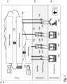
- FIG. 1 provides a system view of an Intelligent PLC integrated into an automation system 100, according to some embodiments of the present invention.
- This example conceptually partitions the industrial environment into a Production Layer 105, a Control Layer 110, and an IT Layer 115.
- most data handling functions are performed at the IT Layer 115.
- the Intelligent PLCs 110E and 110F the system 100 illustrated in FIG. 1 pushes many of these data handling functions down to the Control Layer 110.
- historian capabilities such as efficient data compression for time-series data and intelligent filtering of data may be implemented directly on the Intelligent PLCs 110E and 110F. This allows the Control Layer 115 to utilize high-fidelity data with less storage/communication effort such that few, if any, events go undetected.
- the Intelligent PLCs 110E and 110F also provide rich contextualization functionality. By adding control level knowledge to data, it may not be necessary to re-discover knowledge on Business Analytics 115C at the IT Layer 115. Additionally, in some embodiments, the Intelligent PLCs 110E and 110F provide data analytics functionality directly on their respective device, thus increasing machine and process efficiency.
- one or more production units operate at the Production Layer 105.
- Each production unit sends and receives data through one or more field devices (e.g., Field Device 110A) at the Control Layer 110.
- each field device may be connected to an Intelligent PLC (e.g., Intelligent PLC 110E).
- Data received from the production units is transferred (either directly by the field devices or via an Intelligent PLC) to the IT Layer 115.
- the IT Layer 115 includes systems which perform various post-processing and storage tasks.
- the example of FIG. 1 includes a Supervisory Control and Data Acquisition (SCADA) Server (or Gateway) Component 115A.
- SCADA Supervisory Control and Data Acquisition
- This Component 115A allows an operator to remotely monitor and control the devices at the Control Layer 110 and Production Layer 105. Additionally, the SCADA Server Component 115A collects data from the lower layers 105, 110 and processes the information to make it available to the Unified Plant Knowledge Warehouse 115B. The Unified Plant Knowledge Warehouse 115B provides further processing and storage of the data received from the lower layers 105, 110. Various functionality may be provided by the Unified Plant Knowledge Warehouse 115B. For example, in some embodiments, the Unified Plant Knowledge Warehouse 115B includes functionality for generating analytics based on the data generated by the lower layers 105, 110.
- Each Intelligent PLC 110E and 110F includes three basic portions: a processor (which may include multiple processor cores), a non-transitory, non-volatile memory system, and a data connector providing input/output functionality.
- the non-volatile memory system may take many forms including, for example, a removable memory card or flash drive.
- Applications that may execute within the Intelligent PLCs 110E and 110F are described in greater detail below with reference to FIG. 2 .
- the data connector of Intelligent PLC 110E is connected (wired or wirelessly) to Field Devices 110A and 110B.
- the data connector of Intelligent PLC 110F is connected to Field Devices 110C and 110D. Any field devices known in the art may be used with the Intelligent PLC described herein.
- Example field devices that may be used with the Intelligent PLC include, without limitation, pressure switches, sensors, push buttons, flow switches, and level switches.
- the Intelligent PLCs 110E and 110F may be integrated into the production environment piecemeal.
- Production Units 105B and 105C are connected through their respective field devices to Intelligent PLCs 110E and 110F, while Production Units 105A and 105D communicate directly through their respective Field Devices 110G, 110H, 110I, 110J to the Unified Plant Knowledge Warehouse 115B.
- the Intelligent PLCs 110E and 110F may enrich data using additional context dimensions compared to state of the art systems (e.g., control knowledge, environmental conditions, and service incidences). This allows insights to be made from data analytics with higher confidence and quality.
- the system 100 uses semantic data representation languages and standards for contextualization of data in automation systems. This allows business analytics as well as SCADA-level historians (e.g. OSI PI asset framework) to be configured with minimal effort for integration with data from other systems/devices/sources.
- the system 100 may provide model-based semantic analytics at the Control Layer 110. Thus, analytical algorithms can be updated during device runtime and root cause analysis can be improved by providing explicit access to models (instead of compiled logic in a function block).
- the system 100 introduces a distributed data sharing system in the Control Layer 110 and integrates with external Big Data infrastructures. Thus, applications can access all required data independent from storage location.
- the Intelligent PLCs 110E and 110F may store, utilize, and historize local control-layer parameters and variables, which in conventional automation systems are hidden inside the Control Layer 110.
- FIG. 2 provides an illustration of the system components 200 included in an Intelligent PLC utilizing a knowledge-based controller architecture, according to some embodiments of the present invention.
- Process Image Component 225 is a memory area in a controller's CPU volatile system memory which is updated in each processing/scan cycle based on data associated with the production devices (e.g., the inputs and outputs of connected I/Os).
- the Control Application 230 reads the Process Image Component 225, executes deployed application logic, and writes results back into the Process Image Component 225.
- the process image of each cycle is read and permanently stored on a non-volatile physical storage medium by the Historian Component 220.
- this Historian Component 220 is configured to deploy data compression algorithms to reduce data volume. It thereby can provide applications with access to past process images. Data may be stored either for a fixed time window or as online algorithms which may be used to realize dynamic caching heuristics.
- intelligent data generation algorithms may continuously analyze the process image and context to adjust data generation parameters (e.g. sampling rate) of connected I/Os. For example, for fast changing sensor signals, a high sampling rate may be selected while for slowly changing sensor signals a lower sampling rate is sufficient.
- Data Manager 250 is a module that may be included in some embodiments to provide additional data management functionality at the Historian Component 220.
- the Data Manager 250 may be used to manage the input and output of the system 200. This input and output may include, for example, data from sensors, actuators as well as control variables and control parameters. Traditionally in a controller, this role is realized by the process image alone.
- the Data Manager 250 may also include a database to store historic data for the various inputs and outputs.
- the Data Analytics Component 205 comprises a set of data analysis algorithms that process the current or past process images (queried from the historian). Various data analysis algorithms may be included in the Data Analytics Component 205. For example, in some embodiments, these algorithms include one or more of clustering, classification, logic-based reasoning, and statistical analysis algorithms. Moreover, algorithms may be specified via a model which can be deployed during runtime on the device. The Data Analytics Component 205 may also include various analytical models and dedicated algorithms to interpret these models. The results generated by the Data Analytics Component 205 may be stored in the Historian Component 220, written back to the Process Image Component 225 and/or provided to external components via the Data Connector Component 210. Thus, the Intelligent PLC may be viewed as a device for providing distributed analytics to the other devices in the automation system.
- Automated Reasoner 245 is a module included as part of the Data Analytics Component 205.
- the Automated Reasoner 245 includes at least one reasoning model (implemented in C, C++, Java, etc.) that can be dynamically configured by a declarative knowledge model (e.g. ontology in RDF/OWL standard, predictive model expressed using PMML standard, rules expressed via RIF standard). Based on this configuration, the incoming and outgoing data accessible via the Historian 220 (e.g., data from the Data Manager 250) may be continuously analyzed.
- a declarative knowledge model e.g. ontology in RDF/OWL standard, predictive model expressed using PMML standard, rules expressed via RIF standard.
- Each reasoning model includes one or more reasoning algorithms Examples of automated reasoning algorithms that may be implemented by the Automated Reasoner 245 included, without limitation, deductive reasoning with classical logics and calculi, fuzzy logic, rule engines and logic programming, model checking, Bayesian inference and inductive reasoning methods including machine learning methods.
- the Automated Reasoner 245 can be dynamically configured, it may be used to provide additional functionality not available on static systems. For example, the learning of improved monitoring and alarming functions becomes possible. New knowledge can be detected based on historic data. For example, rules or rule parameters can be learned that allow detection of quality problems in a manufacturing process. These rules can be dynamically deployed in the rule engine and are used automatically in the next control cycle. Additionally, in some embodiments, one or more soft-sensors may be added to the Controller 200. Each soft sensor provides access to a control layer variable that would ordinarily not be accessible outside of the Controller 200. Thus, by dynamically activating a particular soft-sensor, the data may be made available, for example, via the Data Connector 210. Additional information on soft-sensors may be found in International Application No. PCT/US14/63105 entitled "Using Soft-Sensors in a Programmable Logic Controller.”.
- a Contextualization Component 215 annotates incoming data with context information to facilitate its later interpretation.
- Context information may include any information that describes the meaning of data.
- context of data in automation systems may include information about the device that generated the data (e.g., a sensor), about the structure of the automation system (e.g., topology of a plant), about the working mode of the system (e.g., downtime event), about the automation software and its status while the data was generated, and/or about the product/batch that was produced while the data was generated.
- the Contextualization Component 215 is configured to provide data to any of the other components for more specific processing needs.
- the context information generated by the Contextualization Component 215 may not be restricted to the asset structure but may also include control knowledge, product-specific information, process information, event information, and potentially other aspects such external events like weather information. Some context information may be imported from engineering tools (e.g. Siemens Totally Integrated Automation tools). Additionally, in some embodiments, the Contextualization Component 215 provides semantic contextualization.
- the context may be represented by a standard modeling language (e.g. Web Ontology Language, Resource Description Framework) where the meaning of the language constructs is formally defined. Contextualization of data with these semantic modeling standards enables business analytics applications to automatically understand and interpret the data provided from the automation system without manual configuration effort.
- Knowledge Manager 240 is part of the Contextualization Component 215.
- the Knowledge Manager 240 administrates the declarative knowledge models that are received via a Deployment Interface 235 (described below). This administration may include, for example, storing the models and providing an API for accessing and manipulating the models.
- Example representation languages for declarative knowledge model include, without limitation, ontologies in RDF/OWL standard, predictive model expressed using PMML (Predictive Model Markup Language) standard, rules expressed via RIF (Rule Interchange Format) standard, etc.
- the scope of analysis and optimization may be expanded to cover the production processes themselves and is not limited to the Intelligent PLC itself or the area of the directly controlled devices.
- the focus of analytics on the Intelligent PLC may be not only be to ensure the functioning of the Intelligent PLC and its connected sensors and actuators (e.g., HW-specific alarm rules) but also to optimize the controlled production process in a larger context (e.g., based on knowledge of the application domain and infrastructure)
- any data captured or generated by the components of system 200 may be provided to external components via a Data Connector Component 210.
- the Data Connector Component 210 delivers data via a push methodology (i.e., actively sending to external component).
- a pull methodology may be used where data is queried by external component).
- push and pull methodologies may be combined in some embodiments such that the Intelligent PLC is configured to handle both forms of data transfer.
- Deployment Interface 235 is a module included as part of the Data Connector Component 210.
- the Deployment Interface 235 provides access to the knowledge and data management functionality of the system 200 in order to read and write imperative or declarative knowledge, as well as data.
- the Deployment Interface 235 may utilize communication protocols and standards such as, for example, OPC, HTTP, REST, STEP7, TCP/IP, etc.
- Knowledge that is transferred via the Deployment Interface 235 may be expressed using declarative knowledge representation languages/standards as used by the Knowledge Manager 240.
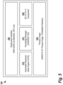
- Process Data 345 includes data written to the Controller 305 by one or more devices involved in a Physical Production Process 350.
- Control Program 340 reads and interprets this data to allow it to provide further instructions for the devices involved in a Physical Production Process 350.
- the Controller 305 comprises one or more Processors 310 and a Storage Medium 315.
- the Processors 310 may include one or more processors, each processor comprising one or more cores.
- the Storage Medium may be used by the Knowledge Manager to store all relevant knowledge models as well as by the Data Manager (see FIG. 2 ) to store all incoming and outgoing data. This data could include, for example, current data (e.g. data of current control cycle) as well as historic data (e.g. data from previous control cycles).
- Pre-defined Reasoning Models 320 are predefined by the control system vendor and Customer Reasoning Models 325 can be dynamically changed by users.
- the Reasoning Models 320, 325 integrate at least one reasoning algorithm (specified in a procedural or declarative way) into the Controller 305 which, in turn, processes the Knowledge Models 330, 335 and incoming data.
- the reasoning algorithms may be adapted to run on the limited resources (e.g. storage space, processing power, data availability, communication bandwidth, programming languages). Additional detail on the implementation of reasoning algorithms is presented above with respect to the Automated Reasoner 245 in FIG.2 .
- the example Storage Medium 315 stores two types of knowledge models.
- Predefined Knowledge Models 330 are predefined by the control system vendor, while Customer Knowledge Models 335 can be dynamically changed by users.
- the knowledge models 330, 335 are connected syntactically via shared signature items, and semantically via assertions on the relation between elements of the different models (such as specialization/generalization, connectedness via relations, etc.).
- Knowledge represented in the Pre-defined Knowledge Models 330 may include, for example, the capabilities of the device, diagnostic knowledge, and data layout.
- the Custom Knowledge Models 335 may build on these to express, for example, process-specific information on parameters, required functionalities, or process-specific analytical functionality.
- an external Server 355 is used. Connection between the Server 355 and Controller 305 is realized using the Deployment Interface (not shown in FIG. 3 ) installed in the controller.
- Customers create a Customer Configuration 360 on the Server 355 with information such as, without limitation, desired rules, parameter, and/or attribute values. Depending on the particular embodiment, customers may create the Customer Configuration 360, for example, by modifying one or more values in an existing configuration file, but answering a set of questions or selecting items presented in a graphical user interface, or by creating a text file specifying the configuration information in a structured language format.
- the Customer Configuration 360 is then transferred to the Deployment Interface on the Controller 350. Once received, the Controller 305 uses the Customer Configuration 360 to dynamically modify the appropriate data items on the Controller 305.
- the Process Data 345, the Knowledge Models 330, 335, and the Reasoning Models 320, 325 are loaded into the Processors 310 where the Reasoning Models 320, 325 are configured with the Knowledge Models 330, 335 and executed based on the Process Data 345.
- the various models execute on the same processor resources as the control program, while in other embodiments, different processor resources are used.
- the control program executes on one core of the Processors 310, while the reasoning algorithms execute on other cores of the Processors 310.
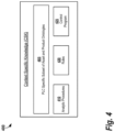
- FIG. 4 provides an illustration of the context specific knowledge (CSK) 400 contained in an example knowledge model, according to some embodiments.
- This knowledge includes Subset of Asset and Product Ontologies 405 which are specific to the particular controller and used to describe the topology of the automation system and production equipment as well as the structure/genealogy of the product.
- knowledge about the control program and its internal dependencies might be available on the PLC via the Control Program 425 portion of the CSK 400.
- Declarative descriptions of Rules 420 and Analytical Procedures 410 formalize the algorithms used for analyzing the data. All knowledge is made accessible via the Knowledge Manager to the Automated Reasoner (see FIG. 2 ).
- the Automated Reasoner evaluates the models based on concrete data from the Historian Component of the PLC (see FIG. 2 ).
- FIG. 5 provides an execution example of a Software Environment 500 as it may be implemented on a S7-1500 PLC a Knowledge-based PLC, according to some embodiments.
- the Process Image 525 in this example includes the software for managing a process image for a SIMATIC S7 Process Image device, as well as embedded historian functionality.
- an IEC 61131-3 Component 520 included in the Software Environment 500 provides support for functionality related to the third part of the open international standard IEC 61131 for programmable logic controllers, IEC 61131-3. As is understood in the art, IEC 61131-3 describes PLC programming languages, as well as concepts and guidelines for creating PLC projects.
- the IEC 61131-3 provides standards regarding the use of programming languages such as Ladder Diagram (LD), Instruction List (IL), Function Block Diagram (FBD), Structured Text (ST) and Sequential Function Chart (SFC).
- LD Ladder Diagram
- IL Instruction List
- BCD Function Block Diagram
- ST Structured Text
- SFC Sequential Function Chart
- the Deployment Interface 505 in this example allows rules and ontology files to be uploaded and changed via interfaces in the existing MiniWeb-Server of the PLC.
- the exchange format can be the CLIPS syntax (as shown in FIG. 5 ) or a standard such as the W3C standard Rule Interchange Format (RIF).
- the rules may be stored, for example, in a dedicated file "rules.clp" which is interpreted each time the run()-method of the rule engine is called. Due to the declarative specification, rules can be changed during runtime of the Intelligent PLC (i.e., between two calls of the run()-method).
- FIG. 6 provides an example code snippet 600 which illustrates how rules can be specified in some embodiments.
- Automated Reasoner 510 enables the declarative specification of processing logic within the Intelligent PLC. It is applied for identification of relevant situations that should be added as event context to the generated sensor data. For detection of relevant situations and for generation of events, a forward chaining rule engine (production rule system) processes all incoming facts (e.g., sensor values) and matches them with the conditions of the rules (left-handside) to determine which rules have to be applied. This processing may be performed, for example, using a conventional algorithm such as the Rete algorithm.
- the Automated Reasoner 510 is implemented using C Language Integrated Production System (CLIPS), a conventional expert system development tool that includes a production rule engine that is based on the Rete algorithm.
- CLIPS C Language Integrated Production System
- the Automated Reasoner allows rules to be specified using ontology classes and instances directly using object patterns.
- the Knowledge Manager 515 administers the declarative knowledge models used in the Software Environment 500.
- Knowledge Manager 515 provides an API for storing the ontology files associated with individual knowledge modes and for querying/updating the files (e.g. what sensors are contained?).
- Each knowledge model may be specified in a document according to the W3C OWL/RDF or OPC-UA standard.
- FIG. 7 provides an example of a document 700 that may be used in some embodiments.
- each knowledge model offers a vocabulary that may be used in defining the rules or for querying the Process Image 525.
- the disclosed technology may be used to reduce maintenance downtime of production line as knowledge can be updated during operation.
- the disclosed technology makes it easy to "inject" expert knowledge into controller, (e.g. adding of diagnostic rules). This allows end-users/domain experts to easily adapt monitoring/alarming functions to their needs.
- there is also less effort to change data analytics and data preparation procedures on controllers e.g. no programming needed to aggregate, translate, etc.
- learning algorithms can make use of the knowledge. In turn, this improves results of analysis (e.g. better predictions, less false positives/negatives) and analytical depth due to better data availability (higher data fidelity and additional control specific knowledge not available outside of the controller).
- control layer devices may include one or more central processing units (CPUs), graphical processing units (GPUs), or any other processor known in the art. More generally, a processor as used herein is a device for executing machine-readable instructions stored on a computer readable medium, for performing tasks and may comprise any one or combination of, hardware and firmware. A processor may also comprise memory storing machine-readable instructions executable for performing tasks. A processor acts upon information by manipulating, analyzing, modifying, converting or transmitting information for use by an executable procedure or an information device, and/or by routing the information to an output device.
- CPUs central processing units
- GPUs graphical processing units
- a processor may use or comprise the capabilities of a computer, controller or microprocessor, for example, and be conditioned using executable instructions to perform special purpose functions not performed by a general purpose computer.
- a processor may be coupled (electrically and/or as comprising executable components) with any other processor enabling interaction and/or communication there-between.
- a user interface processor or generator is a known element comprising electronic circuitry or software or a combination of both for generating display images or portions thereof.
- a user interface comprises one or more display images enabling user interaction with a processor or other device.
- Various devices described herein including, without limitation to the control layer devices and related computing infrastructure, may include at least one computer readable medium or memory for holding instructions programmed according to embodiments of the invention and for containing data structures, tables, records, or other data described herein.
- the term "computer readable medium” as used herein refers to any medium that participates in providing instructions to one or more processors for execution.
- a computer readable medium may take many forms including, but not limited to, non-transitory, non-volatile media, volatile media, and transmission media.
- Non-limiting examples of non-volatile media include optical disks, solid state drives, magnetic disks, and magneto-optical disks.
- Non-limiting examples of volatile media include dynamic memory.
- Non-limiting examples of transmission media include coaxial cables, copper wire, and fiber optics, including the wires that make up a system bus. Transmission media may also take the form of acoustic or light waves, such as those generated during radio wave and infrared data communications.
- An executable application comprises code or machine readable instructions for conditioning the processor to implement predetermined functions, such as those of an operating system, a context data acquisition system or other information processing system, for example, in response to user command or input.
- An executable procedure is a segment of code or machine readable instruction, sub-routine, or other distinct section of code or portion of an executable application for performing one or more particular processes. These processes may include receiving input data and/or parameters, performing operations on received input data and/or performing functions in response to received input parameters, and providing resulting output data and/or parameters.
- a graphical user interface comprises one or more display images, generated by a display processor and enabling user interaction with a processor or other device and associated data acquisition and processing functions.
- the GUI also includes an executable procedure or executable application.
- the executable procedure or executable application conditions the display processor to generate signals representing the GUI display images. These signals are supplied to a display device which displays the image for viewing by the user.
- the processor under control of an executable procedure or executable application, manipulates the GUI display images in response to signals received from the input devices. In this way, the user may interact with the display image using the input devices, enabling user interaction with the processor or other device.
- An activity performed automatically is performed in response to one or more executable instructions or device operations without user direct initiation of the activity.
Landscapes
- Physics & Mathematics (AREA)
- General Physics & Mathematics (AREA)
- Engineering & Computer Science (AREA)
- Automation & Control Theory (AREA)
- Programmable Controllers (AREA)
Claims (12)
- Verfahren zum Betreiben einer intelligenten speicherprogrammierbaren Steuerung (200, 300) über eine Mehrzahl von Abtastzyklen, wobei das Verfahren umfasst:1.1 Ausführen eines Steuerprogramms (340), das Prozessdaten (345) ausliest, die von einer oder mehreren Produktionsvorrichtungen (350) empfangen werden, und Anweisungen zum Steuern der einen oder der mehreren Produktionsvorrichtungen (350) bereitstellt, durch einen Prozessor (310) der intelligenten speicherprogrammierbaren Steuerung (200, 300);1.1.1 Speichern eines vordefinierten Wissensmodells (330) und eines kundenspezifischen Wissensmodells (335), die über gemeinsam genutzte Signaturelemente syntaktisch verbunden sind und über Aussagen über eine Beziehung zwischen Elementen des vordefinierten Wissensmodells (330) und des kundenspezifischen Wissensmodells (335) semantisch verbunden sind, in einem Speichermedium (315) der intelligenten speicherprogrammierbaren Steuerung (200, 300), wobei das kundenspezifische Wissensmodell (335) mindestens eines von prozessspezifischen Informationen über Parameter, erforderlichen Funktionalitäten oder einer prozessspezifischen analytischen Funktionalität ausdrückt;1.1.2 Speichern eines vordefinierten Argumentationsmodells (320) und eines kundenspezifischen Argumentationsmodells (325) im Speichermedium (315) der intelligenten speicherprogrammierbaren Steuerung (200, 300), wobei das vordefinierte Argumentationsmodell (320) und das kundenspezifische Argumentationsmodell (325) einen oder mehrere Argumentationsalgorithmen in die intelligente speicherprogrammierbare Steuerung (200, 300) integrieren;1.3 Ausführen des einen oder der mehreren Argumentationsalgorithmen zum Analysieren von Daten, die über eine Datenkonnektorkomponente (210) der intelligenten speicherprogrammierbaren Steuerung (200, 300) empfangen und gesendet werden, durch eine Datenanalysekomponente (205) mit einem automatisierten Ursachenanalysemodell (245) der intelligenten speicherprogrammierbaren Steuerung (200, 300), wobei die Prozessdaten (345), die Wissensmodelle (330, 335) und die Argumentationsmodelle (320, 325) in den Prozessor (310) geladen werden, wobei die Argumentationsmodelle (320, 325) mit den Wissensmodellen (330, 335) konfiguriert und basierend auf den Prozessdaten (345) ausgeführt werden;wobei das Verfahren gekennzeichnet ist durch:1.4 Empfangen einer Kundenkonfiguration (360) von einem externen Server (355) durch die Datenkonnektorkomponente (210) mit einer Bereitstellungsschnittstelle (235, 505) der intelligenten speicherprogrammierbaren Steuerung (200, 300), wobei die Kundenkonfiguration (360) Informationen aufweist, die Regeln, Parameter und Attributwerte zum Anpassen des kundenspezifischen Wissensmodells (325) und des kundenspezifischen Argumentationsmodells (335) umfassen; und1.5 dynamisches Modifizieren der Konfiguration des einen oder der mehreren Argumentationsalgorithmen durch eine Kontextualisierungskomponente (215) mit einem Wissensverwalter (240) der intelligenten speicherprogrammierbaren Steuerung (200, 300) während der Laufzeit des Steuerprogramms (340) basierend auf der Kundenkonfiguration, während die übrige Funktionalität des Steuerprogramms (340) in einem oder mehreren separaten Verarbeitungsthreads operativ bleibt.
- Verfahren nach Anspruch 1, wobei das vordefinierte Wissensmodell (330) Informationen in Bezug auf eine oder mehrere Fähigkeiten der intelligenten speicherprogrammierbaren Steuerung (200, 300), Diagnosewissen, das an intelligenten speicherprogrammierbaren Steuerung (200, 300) verfügbar ist, und Datenlayoutinformationen umfasst, die von der intelligenten speicherprogrammierbaren Steuerung (200, 300) verwendet werden.
- Verfahren nach Anspruch 1 oder 2, wobei die Kundenkonfiguration (360) durch Erstellen einer Textdatei erstellt wird, die Konfigurationsinformationen in einem strukturierten Sprachformat spezifiziert, und wobei ein benutzerdefiniertes Wissensmodell mindestens eines umfasst von: Ontologien, die durch die Web Ontology Language, OWL, ausgedrückt werden, einem Vorhersagemodell, das unter Verwendung des Standards Predictive Model Markup Language, PMML, ausgedrückt wird, einer oder mehreren Regeln, die unter Verwendung des Standards Rule Interchange Format, RIF, ausgedrückt werden.
- Verfahren nach Anspruch 7, wobei das benutzerdefinierte Wissensmodell eine Angabe eines oder mehrerer Softsensoren umfasst, die im Steuerprogramm verfügbar sind.
- Verfahren nach einem der vorhergehenden Ansprüche, ferner umfassend: Ausführen des Steuerprogramms (340) durch den Prozessor (310) der intelligenten speicherprogrammierbaren Steuerung (200, 300) unter Verwendung eines ersten Kerns des Prozessors (310), der in der intelligenten speicherprogrammierbaren Steuerung (200, 300) enthalten ist,
wobei der eine oder die mehreren Argumentationsalgorithmen unter Verwendung eines zweiten Kerns des Prozessors (310), der in der intelligenten speicherprogrammierbaren Steuerung (200, 300) enthalten ist, dynamisch modifiziert werden. - Intelligente speicherprogrammierbare Steuerung (200, 300), umfassend:einen oder mehrere Prozessoren (310), die zum Ausführen eines Steuerprogramms gemäß einem Abtastzyklus (340) konfiguriert ist, das Prozessdaten (345) ausliest, die von einer oder mehreren Produktionsvorrichtungen (350) in einem industriellen Automatisierungssystem empfangen werden, und Anweisungen zum Steuern der einen oder der mehreren Produktionsvorrichtungen (350) bereitstellt;ein flüchtiges computerlesbares Speichermedium (315), das einen Prozessabbildbereich umfasst;ein nicht-flüchtiges computerlesbares Speichermedium (315) zum Speichern von Folgendem:ein vordefiniertes Wissensmodell (330) und ein kundenspezifisches Wissensmodell (335), die über gemeinsam genutzte Signaturelemente syntaktisch verbunden sind und über Aussagen über eine Beziehung zwischen Elementen des vordefinierten Wissensmodells (330) und des kundenspezifischen Wissensmodells (335) semantisch verbunden sind, wobei das kundenspezifische Wissensmodell (335) mindestens eines von prozessspezifischen Informationen über Parameter, erforderlichen Funktionalitäten oder einer prozessspezifischen analytischen Funktionalität ausdrückt,ein vordefiniertes Argumentationsmodell (320) und ein kundenspezifisches Argumentationsmodell (325), wobei das vordefinierte Argumentationsmodell (320) und das kundenspezifische Argumentationsmodell (325) einen oder mehrere Argumentationsalgorithmen in die intelligente speicherprogrammierbare Steuerung (200, 300) integrieren; undeine Mehrzahl von Steuerungskomponenten, die von dem einen oder den mehreren Prozessoren gemäß dem Abtastzyklus ausgeführt werden, wobei die Mehrzahl von Steuerungskomponenten umfasst:eine Datenanalysekomponente (205) mit einem automatisierten Ursachenanalysemodell (245), konfiguriert zum Ausführen eines oder mehrerer Argumentationsalgorithmen zum Analysieren von Daten, die im Steuerprogramm (340) umfasst sind und über eine Datenkonnektorkomponente (210) empfangen und gesendet werden, wobei die Prozessdaten (345), die Wissensmodelle (330, 335) und die Argumentationsmodelle (320, 325) in den Prozessor (310) geladen werden, wobei die Argumentationsmodelle (320, 325) mit den Wissensmodellen (330, 335) konfiguriert und basierend auf den Prozessdaten (345) ausgeführt werden;wobei die intelligente speicherprogrammierbare Steuerung durch die folgenden Steuerungskomponenten gekennzeichnet ist:die Datenkonnektorkomponente (210) mit einer Bereitstellungsschnittstelle (235, 505), konfiguriert zum Empfangen einer Kundenkonfiguration (360) von einem externen Server (355), wobei die Kundenkonfiguration (360) Informationen aufweist, die Regeln, Parameter und Attributwerte zum Anpassen des kundenspezifischen Wissensmodells (325) und des kundenspezifischen Argumentationsmodells (335) umfassen; undeine Kontextualisierungskomponente (215) mit einem Wissensverwalter (240), konfiguriert zum dynamischen Modifizieren der Konfiguration des einen oder der mehreren Argumentationsalgorithmen während der Laufzeit des Steuerprogramms (340) basierend auf der Kundenkonfiguration, während die übrige Funktionalität des Steuerprogramms (340) in einem oder mehreren separaten Verarbeitungsthreads operativ bleibt.
- Intelligente speicherprogrammierbare Steuerung (200, 300) nach Anspruch 6, wobei die Bereitstellungsschnittstelle (235, 505) eine Webserverschnittstelle umfasst und/oder wobei das automatisierte Ursachenanalysemodell (245) eine Regel-Engine umfasst.
- Intelligente speicherprogrammierbare Steuerung (200, 300) nach Anspruch 6 oder 7, wobei der eine oder die mehreren Prozessoren (110) umfassen:einen ersten Prozessorkern, der zum Ausführen des Steuerprogramms (340) konfiguriert ist; undeinen zweiten Prozessorkern, der zum Modifizieren des einen oder der mehreren Argumentationsalgorithmen parallel zur Ausführung des Steuerprogramms (340) konfiguriert ist.
- Intelligente speicherprogrammierbare Steuerung (200, 300) nach Anspruch 6 bis 7, wobei der eine oder die mehreren Prozessoren (110) eine Mehrzahl von Threads ausführen, die umfasst:einen ersten Thread, der zum Ausführen des Steuerprogramms (340) konfiguriert ist; undeinen oder mehrere zweite Threads, die zum Modifizieren des einen oder der mehreren Argumentationsalgorithmen konfiguriert sind.
- Computerlesbares Medium, das computerausführbare Anweisungen zum Durchführen des Verfahrens nach einem der Ansprüche 1 bis 5 zum Betreiben einer intelligenten speicherprogrammierbare Steuerung (200, 300) nach Anspruch 6 bis 9 speichert.
- Computerlesbares Medium nach Anspruch 10, wobei das vordefinierte Wissensmodell (330) Informationen in Bezug auf eine oder mehrere Fähigkeiten der intelligenten speicherprogrammierbare Steuerung (200, 300), Diagnosewissen, das an der intelligenten speicherprogrammierbaren Steuerung (200, 300) verfügbar ist, und Datenlayoutinformationen umfasst, die von der intelligenten speicherprogrammierbaren Steuerung (200, 300) verwendet werden.
- Computerlesbares Medium nach Anspruch 10, wobei das Verfahren ferner umfasst:Ausführen des Steuerprogramms unter Verwendung eines ersten Kerns eines Prozessors, der in der intelligenten speicherprogrammierbare Steuerung enthalten ist,wobei der eine oder die mehreren Argumentationsalgorithmen unter Verwendung eines zweiten Kerns des Prozessors, der in der intelligenten speicherprogrammierbaren Steuerung (200, 300) enthalten ist, dynamisch modifiziert werden.
Applications Claiming Priority (1)
| Application Number | Priority Date | Filing Date | Title |
|---|---|---|---|
| US14/800,729 US10409254B2 (en) | 2015-07-16 | 2015-07-16 | Knowledge-based programmable logic controller with flexible in-field knowledge management and analytics |
Publications (3)
| Publication Number | Publication Date |
|---|---|
| EP3118697A1 EP3118697A1 (de) | 2017-01-18 |
| EP3118697B1 true EP3118697B1 (de) | 2023-08-23 |
| EP3118697C0 EP3118697C0 (de) | 2023-08-23 |
Family
ID=56920453
Family Applications (1)
| Application Number | Title | Priority Date | Filing Date |
|---|---|---|---|
| EP16179553.9A Active EP3118697B1 (de) | 2015-07-16 | 2016-07-14 | Wissensbasierte programmierbare logiksteuerung mit flexibler feld-wissensverwaltung und -analytik |
Country Status (3)
| Country | Link |
|---|---|
| US (1) | US10409254B2 (de) |
| EP (1) | EP3118697B1 (de) |
| CN (1) | CN106354082B (de) |
Families Citing this family (104)
| Publication number | Priority date | Publication date | Assignee | Title |
|---|---|---|---|---|
| US9411327B2 (en) | 2012-08-27 | 2016-08-09 | Johnson Controls Technology Company | Systems and methods for classifying data in building automation systems |
| US10496067B2 (en) * | 2015-08-07 | 2019-12-03 | Siemens Aktiengesellschaft | Automation and control distributed data management systems |
| US10534326B2 (en) | 2015-10-21 | 2020-01-14 | Johnson Controls Technology Company | Building automation system with integrated building information model |
| WO2017099772A1 (en) * | 2015-12-10 | 2017-06-15 | Siemens Aktiengesellschaft | Distributed embedded data and knowledge management system integrated with plc historian |
| US11947785B2 (en) | 2016-01-22 | 2024-04-02 | Johnson Controls Technology Company | Building system with a building graph |
| US11268732B2 (en) | 2016-01-22 | 2022-03-08 | Johnson Controls Technology Company | Building energy management system with energy analytics |
| US12196437B2 (en) | 2016-01-22 | 2025-01-14 | Tyco Fire & Security Gmbh | Systems and methods for monitoring and controlling an energy plant |
| EP3403148A1 (de) * | 2016-03-24 | 2018-11-21 | Siemens Aktiengesellschaft | Verfahren zur steuerung, steuersystem und anlage |
| WO2017173167A1 (en) | 2016-03-31 | 2017-10-05 | Johnson Controls Technology Company | Hvac device registration in a distributed building management system |
| US11226598B2 (en) | 2016-05-04 | 2022-01-18 | Johnson Controls Technology Company | Building system with user presentation composition based on building context |
| US10505756B2 (en) | 2017-02-10 | 2019-12-10 | Johnson Controls Technology Company | Building management system with space graphs |
| US11774920B2 (en) | 2016-05-04 | 2023-10-03 | Johnson Controls Technology Company | Building system with user presentation composition based on building context |
| US10417451B2 (en) | 2017-09-27 | 2019-09-17 | Johnson Controls Technology Company | Building system with smart entity personal identifying information (PII) masking |
| US10684033B2 (en) | 2017-01-06 | 2020-06-16 | Johnson Controls Technology Company | HVAC system with automated device pairing |
| US11900287B2 (en) | 2017-05-25 | 2024-02-13 | Johnson Controls Tyco IP Holdings LLP | Model predictive maintenance system with budgetary constraints |
| US10095756B2 (en) | 2017-02-10 | 2018-10-09 | Johnson Controls Technology Company | Building management system with declarative views of timeseries data |
| US11307538B2 (en) | 2017-02-10 | 2022-04-19 | Johnson Controls Technology Company | Web services platform with cloud-eased feedback control |
| US11360447B2 (en) | 2017-02-10 | 2022-06-14 | Johnson Controls Technology Company | Building smart entity system with agent based communication and control |
| US11280509B2 (en) | 2017-07-17 | 2022-03-22 | Johnson Controls Technology Company | Systems and methods for agent based building simulation for optimal control |
| US11764991B2 (en) | 2017-02-10 | 2023-09-19 | Johnson Controls Technology Company | Building management system with identity management |
| US11994833B2 (en) | 2017-02-10 | 2024-05-28 | Johnson Controls Technology Company | Building smart entity system with agent based data ingestion and entity creation using time series data |
| US12184444B2 (en) | 2017-02-10 | 2024-12-31 | Johnson Controls Technology Company | Space graph based dynamic control for buildings |
| US10515098B2 (en) | 2017-02-10 | 2019-12-24 | Johnson Controls Technology Company | Building management smart entity creation and maintenance using time series data |
| US10854194B2 (en) | 2017-02-10 | 2020-12-01 | Johnson Controls Technology Company | Building system with digital twin based data ingestion and processing |
| US10452043B2 (en) | 2017-02-10 | 2019-10-22 | Johnson Controls Technology Company | Building management system with nested stream generation |
| US10089276B1 (en) * | 2017-03-17 | 2018-10-02 | Eaton Intelligent Power Limited | Distributed logic control apparatus |
| WO2018175912A1 (en) | 2017-03-24 | 2018-09-27 | Johnson Controls Technology Company | Building management system with dynamic channel communication |
| US11327737B2 (en) | 2017-04-21 | 2022-05-10 | Johnson Controls Tyco IP Holdings LLP | Building management system with cloud management of gateway configurations |
| US10788229B2 (en) | 2017-05-10 | 2020-09-29 | Johnson Controls Technology Company | Building management system with a distributed blockchain database |
| WO2018217251A1 (en) | 2017-05-25 | 2018-11-29 | Johnson Controls Technology Company | Model predictive maintenance system for building equipment |
| US11022947B2 (en) | 2017-06-07 | 2021-06-01 | Johnson Controls Technology Company | Building energy optimization system with economic load demand response (ELDR) optimization and ELDR user interfaces |
| WO2018232147A1 (en) | 2017-06-15 | 2018-12-20 | Johnson Controls Technology Company | Building management system with artificial intelligence for unified agent based control of building subsystems |
| US10401816B2 (en) * | 2017-07-20 | 2019-09-03 | Honeywell International Inc. | Legacy control functions in newgen controllers alongside newgen control functions |
| WO2019018009A1 (en) | 2017-07-21 | 2019-01-24 | Johnson Controls Technology Company | BUILDING MANAGEMENT SYSTEM WITH DYNAMIC RULES WITH SUB-RULE REUSE AND INTELLIGENT EQUATION-CONTROLLED DIAGNOSES |
| US11182047B2 (en) | 2017-07-27 | 2021-11-23 | Johnson Controls Technology Company | Building management system with fault detection and diagnostics visualization |
| WO2019040076A1 (en) * | 2017-08-25 | 2019-02-28 | Siemens Aktiengesellschaft | COGNITIVE AUTOMATION ENGINEERING SYSTEM |
| US11314788B2 (en) | 2017-09-27 | 2022-04-26 | Johnson Controls Tyco IP Holdings LLP | Smart entity management for building management systems |
| US10962945B2 (en) | 2017-09-27 | 2021-03-30 | Johnson Controls Technology Company | Building management system with integration of data into smart entities |
| US11314726B2 (en) | 2017-09-27 | 2022-04-26 | Johnson Controls Tyco IP Holdings LLP | Web services for smart entity management for sensor systems |
| US10565844B2 (en) | 2017-09-27 | 2020-02-18 | Johnson Controls Technology Company | Building risk analysis system with global risk dashboard |
| WO2019067627A1 (en) | 2017-09-27 | 2019-04-04 | Johnson Controls Technology Company | SYSTEMS AND METHODS OF RISK ANALYSIS |
| US11184452B2 (en) * | 2017-10-13 | 2021-11-23 | Yokogawa Electric Corporation | System and method for selecting proxy computer |
| US10809682B2 (en) | 2017-11-15 | 2020-10-20 | Johnson Controls Technology Company | Building management system with optimized processing of building system data |
| US11281169B2 (en) | 2017-11-15 | 2022-03-22 | Johnson Controls Tyco IP Holdings LLP | Building management system with point virtualization for online meters |
| US11127235B2 (en) | 2017-11-22 | 2021-09-21 | Johnson Controls Tyco IP Holdings LLP | Building campus with integrated smart environment |
| WO2019140279A1 (en) | 2018-01-12 | 2019-07-18 | Johnson Controls Technology Company | Building energy optimization system with battery powered vehicle cost optimization |
| EP3514741A1 (de) * | 2018-01-19 | 2019-07-24 | Siemens Aktiengesellschaft | Verfahren und vorrichtung zur dynamischen optimierung industrieller fertigungsprozesse |
| US11954713B2 (en) | 2018-03-13 | 2024-04-09 | Johnson Controls Tyco IP Holdings LLP | Variable refrigerant flow system with electricity consumption apportionment |
| CN108469790B (zh) * | 2018-03-19 | 2020-01-07 | 武汉理工大学 | 一种基于opc协议的plc现场数据采集与监控模块及方法 |
| WO2019240743A1 (en) * | 2018-06-11 | 2019-12-19 | Siemens Aktiengesellschaft | A method and system for semantic integration approach for field device life cycle management |
| US10705511B2 (en) * | 2018-07-11 | 2020-07-07 | Siemens Aktiengesellschaft | Abstraction layers for automation applications |
| EP3818476B1 (de) * | 2018-08-03 | 2025-04-02 | Siemens Aktiengesellschaft | Steuergeräte für neuronale logik |
| US12013676B2 (en) | 2018-08-20 | 2024-06-18 | Siemens Aktiengesellschaft | Programmable logic controller-based modular acceleration module for artificial intelligence |
| US11016648B2 (en) | 2018-10-30 | 2021-05-25 | Johnson Controls Technology Company | Systems and methods for entity visualization and management with an entity node editor |
| US11334044B2 (en) | 2018-11-19 | 2022-05-17 | Johnson Controls Tyco IP Holdings LLP | Building system with semantic modeling based searching |
| US11927925B2 (en) | 2018-11-19 | 2024-03-12 | Johnson Controls Tyco IP Holdings LLP | Building system with a time correlated reliability data stream |
| US12367443B2 (en) | 2019-01-14 | 2025-07-22 | Tyco Fire & Security Gmbh | System and method for showing key performance indicators |
| US11436567B2 (en) | 2019-01-18 | 2022-09-06 | Johnson Controls Tyco IP Holdings LLP | Conference room management system |
| US10788798B2 (en) | 2019-01-28 | 2020-09-29 | Johnson Controls Technology Company | Building management system with hybrid edge-cloud processing |
| DE102019203921A1 (de) * | 2019-03-22 | 2020-09-24 | Zf Friedrichshafen Ag | Automatisierungsanordnung, Verfahren zum Betrieb der Automatisierungsanordnung sowie Computerprogramm |
| CN110134405B (zh) * | 2019-04-18 | 2022-11-11 | 福建星云电子股份有限公司 | 一种灵活的向制造执行系统上传数据的方法及装置 |
| EP3997530B1 (de) * | 2019-08-16 | 2023-11-08 | Siemens Aktiengesellschaft | Künstliche intelligenz für engineering in der automatisierungstechnik |
| US12265367B2 (en) * | 2019-10-14 | 2025-04-01 | Siemens Aktiengesellschaft | Artificial intelligence (AI) companions for function blocks in a programmable logic controller (PLC) program for integrating AI in automation |
| EP3812985A1 (de) * | 2019-10-22 | 2021-04-28 | Siemens Aktiengesellschaft | Automatisierungskomponente und verfahren zu deren betrieb auf der basis eines erweiterten informationsmodells |
| US11307554B2 (en) * | 2019-11-20 | 2022-04-19 | Younes Faraj | System and method for keyword-based PLC programming |
| WO2021106082A1 (ja) | 2019-11-26 | 2021-06-03 | 東芝三菱電機産業システム株式会社 | Scadaウェブhmiシステム |
| CN110989483A (zh) * | 2019-11-28 | 2020-04-10 | 昆明昆船物流信息产业有限公司 | 物流模块化控制单元、控制系统及单元和系统的设计方法 |
| US12197299B2 (en) | 2019-12-20 | 2025-01-14 | Tyco Fire & Security Gmbh | Building system with ledger based software gateways |
| CN111191460B (zh) * | 2019-12-30 | 2023-01-03 | 福州大学 | 一种结合逻辑规则和碎片化知识的关系预测方法 |
| US20210200713A1 (en) | 2019-12-31 | 2021-07-01 | Johnson Controls Technology Company | Systems and methods for generating a data structure from multiple bim files |
| EP4085345A1 (de) | 2019-12-31 | 2022-11-09 | Johnson Controls Tyco IP Holdings LLP | Gebäudedatenplattform |
| US12021650B2 (en) | 2019-12-31 | 2024-06-25 | Tyco Fire & Security Gmbh | Building data platform with event subscriptions |
| US11769066B2 (en) | 2021-11-17 | 2023-09-26 | Johnson Controls Tyco IP Holdings LLP | Building data platform with digital twin triggers and actions |
| US11894944B2 (en) | 2019-12-31 | 2024-02-06 | Johnson Controls Tyco IP Holdings LLP | Building data platform with an enrichment loop |
| US12100280B2 (en) | 2020-02-04 | 2024-09-24 | Tyco Fire & Security Gmbh | Systems and methods for software defined fire detection and risk assessment |
| EP4092499A4 (de) * | 2020-02-19 | 2023-10-18 | Siemens Aktiengesellschaft | Verfahren und gerät zum aufbau einer wissensbasis, fabriksystem und rechnervorrichtung |
| US11537386B2 (en) | 2020-04-06 | 2022-12-27 | Johnson Controls Tyco IP Holdings LLP | Building system with dynamic configuration of network resources for 5G networks |
| US11874809B2 (en) | 2020-06-08 | 2024-01-16 | Johnson Controls Tyco IP Holdings LLP | Building system with naming schema encoding entity type and entity relationships |
| US12346381B2 (en) | 2020-09-30 | 2025-07-01 | Tyco Fire & Security Gmbh | Building management system with semantic model integration |
| US11954154B2 (en) | 2020-09-30 | 2024-04-09 | Johnson Controls Tyco IP Holdings LLP | Building management system with semantic model integration |
| US11397773B2 (en) | 2020-09-30 | 2022-07-26 | Johnson Controls Tyco IP Holdings LLP | Building management system with semantic model integration |
| US12063274B2 (en) | 2020-10-30 | 2024-08-13 | Tyco Fire & Security Gmbh | Self-configuring building management system |
| US12061453B2 (en) | 2020-12-18 | 2024-08-13 | Tyco Fire & Security Gmbh | Building management system performance index |
| US12235617B2 (en) | 2021-02-08 | 2025-02-25 | Tyco Fire & Security Gmbh | Site command and control tool with dynamic model viewer |
| WO2022197964A1 (en) | 2021-03-17 | 2022-09-22 | Johnson Controls Tyco IP Holdings LLP | Systems and methods for determining equipment energy waste |
| CN113093525A (zh) * | 2021-04-02 | 2021-07-09 | 北京世纪隆博科技有限责任公司 | 一种ipc智能控制系统及方法 |
| US12321727B2 (en) | 2021-05-25 | 2025-06-03 | Siemens Aktiengesellschaft | Data interaction method, apparatus and system for AI inference device and automation controller |
| US12523975B2 (en) | 2021-06-08 | 2026-01-13 | Tyco Fire & Security Gmbh | Building management system with intelligent visualization |
| US11899723B2 (en) | 2021-06-22 | 2024-02-13 | Johnson Controls Tyco IP Holdings LLP | Building data platform with context based twin function processing |
| US11796974B2 (en) | 2021-11-16 | 2023-10-24 | Johnson Controls Tyco IP Holdings LLP | Building data platform with schema extensibility for properties and tags of a digital twin |
| US11934966B2 (en) | 2021-11-17 | 2024-03-19 | Johnson Controls Tyco IP Holdings LLP | Building data platform with digital twin inferences |
| US12399467B2 (en) | 2021-11-17 | 2025-08-26 | Tyco Fire & Security Gmbh | Building management systems and methods for tuning fault detection thresholds |
| US11704311B2 (en) | 2021-11-24 | 2023-07-18 | Johnson Controls Tyco IP Holdings LLP | Building data platform with a distributed digital twin |
| US12013673B2 (en) | 2021-11-29 | 2024-06-18 | Tyco Fire & Security Gmbh | Building control system using reinforcement learning |
| US12412003B2 (en) | 2021-11-29 | 2025-09-09 | Tyco Fire & Security Gmbh | Building data platform with digital twin based predictive recommendation visualization |
| US11714930B2 (en) | 2021-11-29 | 2023-08-01 | Johnson Controls Tyco IP Holdings LLP | Building data platform with digital twin based inferences and predictions for a graphical building model |
| US12333657B2 (en) | 2021-12-01 | 2025-06-17 | Tyco Fire & Security Gmbh | Building data platform with augmented reality based digital twins |
| US12541182B2 (en) | 2021-12-21 | 2026-02-03 | Tyco Fire & Security Gmbh | Building data platform with analytics development |
| US12481259B2 (en) | 2022-01-03 | 2025-11-25 | Tyco Fire & Security Gmbh | Building platform chip for digital twins |
| US12372955B2 (en) | 2022-05-05 | 2025-07-29 | Tyco Fire & Security Gmbh | Building data platform with digital twin functionality indicators |
| US12529491B2 (en) | 2022-05-05 | 2026-01-20 | Tyco Fire & Security Gmbh | Building data platform with digital twin-based diagnostic routines |
| US12061633B2 (en) | 2022-09-08 | 2024-08-13 | Tyco Fire & Security Gmbh | Building system that maps points into a graph schema |
| US12013823B2 (en) | 2022-09-08 | 2024-06-18 | Tyco Fire & Security Gmbh | Gateway system that maps points into a graph schema |
| US12523999B2 (en) | 2022-10-20 | 2026-01-13 | Tyco Fire & Security Gmbh | Building management system with intelligent fault visualization |
Family Cites Families (5)
| Publication number | Priority date | Publication date | Assignee | Title |
|---|---|---|---|---|
| US20080313228A1 (en) | 2007-06-15 | 2008-12-18 | Rockwell Automation Technologies, Inc. | Controller log and log aggregation |
| US7930639B2 (en) | 2007-09-26 | 2011-04-19 | Rockwell Automation Technologies, Inc. | Contextualization for historians in industrial systems |
| US8751777B2 (en) | 2011-01-28 | 2014-06-10 | Honeywell International Inc. | Methods and reconfigurable systems to optimize the performance of a condition based health maintenance system |
| US9310790B2 (en) | 2011-05-23 | 2016-04-12 | Honeywell International Inc. | Large-scale comprehensive real-time monitoring framework for industrial facilities |
| DE102012207437B3 (de) * | 2012-05-04 | 2013-05-29 | Siemens Aktiengesellschaft | Verfahren zum Betrieb einer speicherprogrammierbaren Steuerung |
-
2015
- 2015-07-16 US US14/800,729 patent/US10409254B2/en active Active
-
2016
- 2016-07-14 EP EP16179553.9A patent/EP3118697B1/de active Active
- 2016-07-15 CN CN201610559254.6A patent/CN106354082B/zh active Active
Also Published As
| Publication number | Publication date |
|---|---|
| CN106354082B (zh) | 2020-01-21 |
| US20170017221A1 (en) | 2017-01-19 |
| CN106354082A (zh) | 2017-01-25 |
| EP3118697A1 (de) | 2017-01-18 |
| US10409254B2 (en) | 2019-09-10 |
| EP3118697C0 (de) | 2023-08-23 |
Similar Documents
| Publication | Publication Date | Title |
|---|---|---|
| EP3118697B1 (de) | Wissensbasierte programmierbare logiksteuerung mit flexibler feld-wissensverwaltung und -analytik | |
| US10739746B2 (en) | Using soft-sensors in a programmable logic controller | |
| US11567783B2 (en) | Data format transformation for downstream processing in a data pipeline | |
| US10809692B2 (en) | Control contextualization and reasoning about control | |
| CN109597666B (zh) | 用于利用历史过程参数来自动填充显示区域的系统和方法 | |
| EP3335083B1 (de) | Reichhaltige kontextualisierung von automatisierungsdaten | |
| EP3465553B1 (de) | Ein kognitives automatisierungssystem | |
| US10809708B2 (en) | Generating events using contextual information on an intelligent programmable logic controller | |
| EP3602216B1 (de) | Prozessabbild in steuergeräten, das die sichtbarkeit und zugänglichkeit von objekten der realen welt ermöglicht | |
| JP7387336B2 (ja) | プロセスグラフィックスにウェブフレームを埋め込むためのシステムおよび方法 | |
| CN107250932B (zh) | 可编程逻辑控制器及其中的语义情境化方法 | |
| US10303148B2 (en) | Automatic compression algorithm selection and parameter tuning based on contextual knowledge | |
| EP4155849A1 (de) | Modellbestandsbibliothek und empfehlungsmaschine für industrielle automatisierungsumgebungen | |
| Majumder et al. | Digital Twin Architecture Patterns for Real-Time Control Systems |
Legal Events
| Date | Code | Title | Description |
|---|---|---|---|
| PUAI | Public reference made under article 153(3) epc to a published international application that has entered the european phase |
Free format text: ORIGINAL CODE: 0009012 |
|
| STAA | Information on the status of an ep patent application or granted ep patent |
Free format text: STATUS: THE APPLICATION HAS BEEN PUBLISHED |
|
| AK | Designated contracting states |
Kind code of ref document: A1 Designated state(s): AL AT BE BG CH CY CZ DE DK EE ES FI FR GB GR HR HU IE IS IT LI LT LU LV MC MK MT NL NO PL PT RO RS SE SI SK SM TR |
|
| AX | Request for extension of the european patent |
Extension state: BA ME |
|
| STAA | Information on the status of an ep patent application or granted ep patent |
Free format text: STATUS: REQUEST FOR EXAMINATION WAS MADE |
|
| 17P | Request for examination filed |
Effective date: 20170705 |
|
| RBV | Designated contracting states (corrected) |
Designated state(s): AL AT BE BG CH CY CZ DE DK EE ES FI FR GB GR HR HU IE IS IT LI LT LU LV MC MK MT NL NO PL PT RO RS SE SI SK SM TR |
|
| RAP1 | Party data changed (applicant data changed or rights of an application transferred) |
Owner name: SIEMENS AKTIENGESELLSCHAFT |
|
| STAA | Information on the status of an ep patent application or granted ep patent |
Free format text: STATUS: EXAMINATION IS IN PROGRESS |
|
| 17Q | First examination report despatched |
Effective date: 20190607 |
|
| GRAP | Despatch of communication of intention to grant a patent |
Free format text: ORIGINAL CODE: EPIDOSNIGR1 |
|
| STAA | Information on the status of an ep patent application or granted ep patent |
Free format text: STATUS: GRANT OF PATENT IS INTENDED |
|
| INTG | Intention to grant announced |
Effective date: 20230315 |
|
| GRAS | Grant fee paid |
Free format text: ORIGINAL CODE: EPIDOSNIGR3 |
|
| GRAA | (expected) grant |
Free format text: ORIGINAL CODE: 0009210 |
|
| STAA | Information on the status of an ep patent application or granted ep patent |
Free format text: STATUS: THE PATENT HAS BEEN GRANTED |
|
| AK | Designated contracting states |
Kind code of ref document: B1 Designated state(s): AL AT BE BG CH CY CZ DE DK EE ES FI FR GB GR HR HU IE IS IT LI LT LU LV MC MK MT NL NO PL PT RO RS SE SI SK SM TR |
|
| REG | Reference to a national code |
Ref country code: GB Ref legal event code: FG4D |
|
| REG | Reference to a national code |
Ref country code: CH Ref legal event code: EP |
|
| REG | Reference to a national code |
Ref country code: DE Ref legal event code: R096 Ref document number: 602016082092 Country of ref document: DE |
|
| REG | Reference to a national code |
Ref country code: IE Ref legal event code: FG4D |
|
| U01 | Request for unitary effect filed |
Effective date: 20230823 |
|
| U07 | Unitary effect registered |
Designated state(s): AT BE BG DE DK EE FI FR IT LT LU LV MT NL PT SE SI Effective date: 20230828 |
|
| PG25 | Lapsed in a contracting state [announced via postgrant information from national office to epo] |
Ref country code: GR Free format text: LAPSE BECAUSE OF FAILURE TO SUBMIT A TRANSLATION OF THE DESCRIPTION OR TO PAY THE FEE WITHIN THE PRESCRIBED TIME-LIMIT Effective date: 20231124 |
|
| PG25 | Lapsed in a contracting state [announced via postgrant information from national office to epo] |
Ref country code: IS Free format text: LAPSE BECAUSE OF FAILURE TO SUBMIT A TRANSLATION OF THE DESCRIPTION OR TO PAY THE FEE WITHIN THE PRESCRIBED TIME-LIMIT Effective date: 20231223 |
|
| PG25 | Lapsed in a contracting state [announced via postgrant information from national office to epo] |
Ref country code: RS Free format text: LAPSE BECAUSE OF FAILURE TO SUBMIT A TRANSLATION OF THE DESCRIPTION OR TO PAY THE FEE WITHIN THE PRESCRIBED TIME-LIMIT Effective date: 20230823 Ref country code: NO Free format text: LAPSE BECAUSE OF FAILURE TO SUBMIT A TRANSLATION OF THE DESCRIPTION OR TO PAY THE FEE WITHIN THE PRESCRIBED TIME-LIMIT Effective date: 20231123 Ref country code: IS Free format text: LAPSE BECAUSE OF FAILURE TO SUBMIT A TRANSLATION OF THE DESCRIPTION OR TO PAY THE FEE WITHIN THE PRESCRIBED TIME-LIMIT Effective date: 20231223 Ref country code: HR Free format text: LAPSE BECAUSE OF FAILURE TO SUBMIT A TRANSLATION OF THE DESCRIPTION OR TO PAY THE FEE WITHIN THE PRESCRIBED TIME-LIMIT Effective date: 20230823 Ref country code: GR Free format text: LAPSE BECAUSE OF FAILURE TO SUBMIT A TRANSLATION OF THE DESCRIPTION OR TO PAY THE FEE WITHIN THE PRESCRIBED TIME-LIMIT Effective date: 20231124 |
|
| PG25 | Lapsed in a contracting state [announced via postgrant information from national office to epo] |
Ref country code: PL Free format text: LAPSE BECAUSE OF FAILURE TO SUBMIT A TRANSLATION OF THE DESCRIPTION OR TO PAY THE FEE WITHIN THE PRESCRIBED TIME-LIMIT Effective date: 20230823 |
|
| PG25 | Lapsed in a contracting state [announced via postgrant information from national office to epo] |
Ref country code: ES Free format text: LAPSE BECAUSE OF FAILURE TO SUBMIT A TRANSLATION OF THE DESCRIPTION OR TO PAY THE FEE WITHIN THE PRESCRIBED TIME-LIMIT Effective date: 20230823 |
|
| PG25 | Lapsed in a contracting state [announced via postgrant information from national office to epo] |
Ref country code: SM Free format text: LAPSE BECAUSE OF FAILURE TO SUBMIT A TRANSLATION OF THE DESCRIPTION OR TO PAY THE FEE WITHIN THE PRESCRIBED TIME-LIMIT Effective date: 20230823 Ref country code: RO Free format text: LAPSE BECAUSE OF FAILURE TO SUBMIT A TRANSLATION OF THE DESCRIPTION OR TO PAY THE FEE WITHIN THE PRESCRIBED TIME-LIMIT Effective date: 20230823 Ref country code: ES Free format text: LAPSE BECAUSE OF FAILURE TO SUBMIT A TRANSLATION OF THE DESCRIPTION OR TO PAY THE FEE WITHIN THE PRESCRIBED TIME-LIMIT Effective date: 20230823 Ref country code: CZ Free format text: LAPSE BECAUSE OF FAILURE TO SUBMIT A TRANSLATION OF THE DESCRIPTION OR TO PAY THE FEE WITHIN THE PRESCRIBED TIME-LIMIT Effective date: 20230823 Ref country code: SK Free format text: LAPSE BECAUSE OF FAILURE TO SUBMIT A TRANSLATION OF THE DESCRIPTION OR TO PAY THE FEE WITHIN THE PRESCRIBED TIME-LIMIT Effective date: 20230823 |
|
| REG | Reference to a national code |
Ref country code: DE Ref legal event code: R097 Ref document number: 602016082092 Country of ref document: DE |
|
| PLBE | No opposition filed within time limit |
Free format text: ORIGINAL CODE: 0009261 |
|
| STAA | Information on the status of an ep patent application or granted ep patent |
Free format text: STATUS: NO OPPOSITION FILED WITHIN TIME LIMIT |
|
| 26N | No opposition filed |
Effective date: 20240524 |
|
| U20 | Renewal fee for the european patent with unitary effect paid |
Year of fee payment: 9 Effective date: 20240719 |
|
| PG25 | Lapsed in a contracting state [announced via postgrant information from national office to epo] |
Ref country code: MC Free format text: LAPSE BECAUSE OF FAILURE TO SUBMIT A TRANSLATION OF THE DESCRIPTION OR TO PAY THE FEE WITHIN THE PRESCRIBED TIME-LIMIT Effective date: 20230823 |
|
| REG | Reference to a national code |
Ref country code: CH Ref legal event code: PL |
|
| GBPC | Gb: european patent ceased through non-payment of renewal fee |
Effective date: 20240714 |
|
| PG25 | Lapsed in a contracting state [announced via postgrant information from national office to epo] |
Ref country code: CH Free format text: LAPSE BECAUSE OF NON-PAYMENT OF DUE FEES Effective date: 20240731 |
|
| PG25 | Lapsed in a contracting state [announced via postgrant information from national office to epo] |
Ref country code: GB Free format text: LAPSE BECAUSE OF NON-PAYMENT OF DUE FEES Effective date: 20240714 |
|
| PG25 | Lapsed in a contracting state [announced via postgrant information from national office to epo] |
Ref country code: IE Free format text: LAPSE BECAUSE OF NON-PAYMENT OF DUE FEES Effective date: 20240714 |
|
| U20 | Renewal fee for the european patent with unitary effect paid |
Year of fee payment: 10 Effective date: 20250718 |
|
| PG25 | Lapsed in a contracting state [announced via postgrant information from national office to epo] |
Ref country code: CY Free format text: LAPSE BECAUSE OF FAILURE TO SUBMIT A TRANSLATION OF THE DESCRIPTION OR TO PAY THE FEE WITHIN THE PRESCRIBED TIME-LIMIT; INVALID AB INITIO Effective date: 20160714 |