EP3118591B1 - Füllstandmessgerät - Google Patents
Füllstandmessgerät Download PDFInfo
- Publication number
- EP3118591B1 EP3118591B1 EP15176941.1A EP15176941A EP3118591B1 EP 3118591 B1 EP3118591 B1 EP 3118591B1 EP 15176941 A EP15176941 A EP 15176941A EP 3118591 B1 EP3118591 B1 EP 3118591B1
- Authority
- EP
- European Patent Office
- Prior art keywords
- line
- input
- fill level
- measurement device
- level measurement
- Prior art date
- Legal status (The legal status is an assumption and is not a legal conclusion. Google has not performed a legal analysis and makes no representation as to the accuracy of the status listed.)
- Active
Links
- 238000005259 measurement Methods 0.000 title claims description 17
- 239000000523 sample Substances 0.000 claims description 66
- 238000011156 evaluation Methods 0.000 claims description 22
- 238000010586 diagram Methods 0.000 description 7
- 238000000034 method Methods 0.000 description 6
- 238000001514 detection method Methods 0.000 description 5
- 230000001419 dependent effect Effects 0.000 description 4
- 230000015572 biosynthetic process Effects 0.000 description 3
- 239000000463 material Substances 0.000 description 3
- 230000006978 adaptation Effects 0.000 description 2
- 238000013461 design Methods 0.000 description 2
- 230000001681 protective effect Effects 0.000 description 2
- 239000013590 bulk material Substances 0.000 description 1
- 239000003990 capacitor Substances 0.000 description 1
- 238000011161 development Methods 0.000 description 1
- 230000018109 developmental process Effects 0.000 description 1
- 230000000694 effects Effects 0.000 description 1
- 230000005284 excitation Effects 0.000 description 1
- 238000009434 installation Methods 0.000 description 1
- 239000007787 solid Substances 0.000 description 1
Images

Classifications
-
- G—PHYSICS
- G01—MEASURING; TESTING
- G01F—MEASURING VOLUME, VOLUME FLOW, MASS FLOW OR LIQUID LEVEL; METERING BY VOLUME
- G01F23/00—Indicating or measuring liquid level or level of fluent solid material, e.g. indicating in terms of volume or indicating by means of an alarm
- G01F23/22—Indicating or measuring liquid level or level of fluent solid material, e.g. indicating in terms of volume or indicating by means of an alarm by measuring physical variables, other than linear dimensions, pressure or weight, dependent on the level to be measured, e.g. by difference of heat transfer of steam or water
- G01F23/26—Indicating or measuring liquid level or level of fluent solid material, e.g. indicating in terms of volume or indicating by means of an alarm by measuring physical variables, other than linear dimensions, pressure or weight, dependent on the level to be measured, e.g. by difference of heat transfer of steam or water by measuring variations of capacity or inductance of capacitors or inductors arising from the presence of liquid or fluent solid material in the electric or electromagnetic fields
- G01F23/263—Indicating or measuring liquid level or level of fluent solid material, e.g. indicating in terms of volume or indicating by means of an alarm by measuring physical variables, other than linear dimensions, pressure or weight, dependent on the level to be measured, e.g. by difference of heat transfer of steam or water by measuring variations of capacity or inductance of capacitors or inductors arising from the presence of liquid or fluent solid material in the electric or electromagnetic fields by measuring variations in capacitance of capacitors
- G01F23/266—Indicating or measuring liquid level or level of fluent solid material, e.g. indicating in terms of volume or indicating by means of an alarm by measuring physical variables, other than linear dimensions, pressure or weight, dependent on the level to be measured, e.g. by difference of heat transfer of steam or water by measuring variations of capacity or inductance of capacitors or inductors arising from the presence of liquid or fluent solid material in the electric or electromagnetic fields by measuring variations in capacitance of capacitors measuring circuits therefor
-
- G—PHYSICS
- G01—MEASURING; TESTING
- G01F—MEASURING VOLUME, VOLUME FLOW, MASS FLOW OR LIQUID LEVEL; METERING BY VOLUME
- G01F23/00—Indicating or measuring liquid level or level of fluent solid material, e.g. indicating in terms of volume or indicating by means of an alarm
- G01F23/22—Indicating or measuring liquid level or level of fluent solid material, e.g. indicating in terms of volume or indicating by means of an alarm by measuring physical variables, other than linear dimensions, pressure or weight, dependent on the level to be measured, e.g. by difference of heat transfer of steam or water
- G01F23/26—Indicating or measuring liquid level or level of fluent solid material, e.g. indicating in terms of volume or indicating by means of an alarm by measuring physical variables, other than linear dimensions, pressure or weight, dependent on the level to be measured, e.g. by difference of heat transfer of steam or water by measuring variations of capacity or inductance of capacitors or inductors arising from the presence of liquid or fluent solid material in the electric or electromagnetic fields
- G01F23/263—Indicating or measuring liquid level or level of fluent solid material, e.g. indicating in terms of volume or indicating by means of an alarm by measuring physical variables, other than linear dimensions, pressure or weight, dependent on the level to be measured, e.g. by difference of heat transfer of steam or water by measuring variations of capacity or inductance of capacitors or inductors arising from the presence of liquid or fluent solid material in the electric or electromagnetic fields by measuring variations in capacitance of capacitors
- G01F23/265—Indicating or measuring liquid level or level of fluent solid material, e.g. indicating in terms of volume or indicating by means of an alarm by measuring physical variables, other than linear dimensions, pressure or weight, dependent on the level to be measured, e.g. by difference of heat transfer of steam or water by measuring variations of capacity or inductance of capacitors or inductors arising from the presence of liquid or fluent solid material in the electric or electromagnetic fields by measuring variations in capacitance of capacitors for discrete levels
-
- G—PHYSICS
- G01—MEASURING; TESTING
- G01F—MEASURING VOLUME, VOLUME FLOW, MASS FLOW OR LIQUID LEVEL; METERING BY VOLUME
- G01F23/00—Indicating or measuring liquid level or level of fluent solid material, e.g. indicating in terms of volume or indicating by means of an alarm
- G01F23/22—Indicating or measuring liquid level or level of fluent solid material, e.g. indicating in terms of volume or indicating by means of an alarm by measuring physical variables, other than linear dimensions, pressure or weight, dependent on the level to be measured, e.g. by difference of heat transfer of steam or water
- G01F23/28—Indicating or measuring liquid level or level of fluent solid material, e.g. indicating in terms of volume or indicating by means of an alarm by measuring physical variables, other than linear dimensions, pressure or weight, dependent on the level to be measured, e.g. by difference of heat transfer of steam or water by measuring the variations of parameters of electromagnetic or acoustic waves applied directly to the liquid or fluent solid material
Definitions
- the present invention relates to a level measuring device according to the preamble of patent claim 1.
- Level measuring devices and methods for determining the filling level of a filling or bulk material in a container are known from the prior art and are used, for example, to detect whether a filling level is above or below a predefined filling state. Such devices are often referred to as level limit switch.
- Level gauges are off, for example DE 30 44 353 A1 . US 2009/151446 A1 . DE 10 2009 060 742 A1 , and US 3,140,608 known.
- Level limit switches can be based on very different physical principles.
- One of these principles is the evaluation of a capacitance, which forms between a measuring electrode and a reference electrode, wherein the filling material fills a space between reference and measuring electrode when filling the container, thereby changing the capacity formed by them.
- One method of determining capacitance is the formation of an electrical resonant circuit incorporating the capacitance of interest. The resonant frequency of the resonant circuit characterizes the size of the capacitance to be measured.
- the resonant circuit can be designed, for example, as a series resonant circuit with series connection of an inductance with a capacitance.
- a designed as an elongated probe line generates reflections of an electrical AC voltage fed, from which forms a standing voltage wave on the probe.
- the voltage which can be measured there shows a resonant behavior due to the standing wave, the line length determining the resonance points.
- the line probe Upon contact of the line probe with filling results in capacity and / or additional reflections due to the contents changes in the frequency position of the resonance points. These can be evaluated with regard to a limit level message.
- the excitation of an electrical resonance circuit causes the feeding of an AC signal via an AC voltage generator.
- the resonance frequency can be found. It is characterized either by a voltage increase or a voltage minimum. The detection of the alternating voltage amplitude over the frequency thus allows the determination of the resonance point (s).
- some applications of these principles of level detection of contents require installation of the sensor from above through an existing opening in the container lid. If, at the same time, the switching point of the limit switch does not lie in the upper region of the container, ie in the vicinity of the container cover, but further down, then the detecting electrode or probe must extend over the extension desired container height can be brought. It is advantageous if the sensor electronics outside the container, in this case above the container lid, can be attached. This has the consequence that the probe must be discontinued over an extension of the electronics. This deductibility is also required in applications with very high temperatures in the container, so that the electronics further away from the probe and the temperatures prevailing there can be easily operated.
- a fill level measuring device has electronics with a signal generator for generating an alternating voltage and a signal detector for detecting an alternating voltage reflected at a resonant measuring probe with an input, and a connecting element which electrically and mechanically connects the electronics to the resonance measuring probe, and is thereby characterized in that the connecting element has a first connecting line, which connects the signal generator to the input of the measuring probe, and a second connecting line, which connects the input of the measuring probe to the signal detector.
- the first connection line connects the AC generator to the probe and the second connection line connects the probe to the AC detector.
- the connecting lines and the AC voltage generator or the AC voltage detector are advantageously matched as well as possible in their impedance to each other.
- a line impedance of the first connection line and an input impedance of the output of the AC voltage generator and a line impedance of the second connection line and an input impedance of the input of the AC voltage detector are advantageously adapted to one another. In this way, it is true that the formation of line resonances on the first connecting line can not be prevented in principle, but the AC voltage detector, which is connected to the measuring probe via the second connecting line, no longer detects it.
- the first connection line and the input impedance of the signal generator output are adapted to one another in such a way that a reflection factor for an alternating voltage returning to the output of the signal generator is minimized, in particular zero.
- the second connecting line and the input impedance of the signal detector input are adapted to each other such that a reflection factor at the input of the signal detector is minimized, in particular zero.
- FIG. 1 is an application example of a level gauge 101 shown as a level limit switch or level sensor, wherein the level limit switch is disposed above a Gregutober Structure 102.
- the filling material is located in a container 103. If the product surface 102 in the region of the measuring device 101 exceeds a certain level 104, the so-called limit level, the device should signal that the limit value 104 has been exceeded.
- the device 101 is connected via one or more lines 105 to a display and / or control unit, not shown here, which responds to the output signal of the level sensor 101. Via the line (s) 105, the level sensor 101 can also be supplied with electrical energy.
- an energy source and / or an energy store may be present in or at the measuring device.
- the lines 105 could be completely dispensed with if the sensor 101 transmits its information wirelessly to a suitable remote station.
- the level limit switch 101 usually consists of a sensor, for which the term probe 106 is used synonymously here, and a control and evaluation electronics 107.
- the probe 106 is located inside the container 103, so that it can come into contact with the product. It has, for example, a rod-like shape whose vertical extent, depending on the design, ranges between a few millimeters and a few centimeters. This is followed by a likewise rod-shaped connecting part 108, which is the electrical and mechanical connection of the probe 106 with the control and evaluation electronics 107 is used.
- control and evaluation electronics 107 is advantageously mounted outside of the container 103 and within a protective protective housing not shown here. Between control and evaluation electronics 107 and probe 106 is a process adaptation 109, which connects the two parts together and produces the appropriate mounting connection with a container ceiling.
- the positioning of the probe 106 must be modified accordingly. This is in FIG. 1 shown in dashed lines. The sensitive probe 106 is therefore further down in the container 103, resulting in a greater distance between the probe 106 and the control and evaluation electronics 107 results, which is to be bridged by the connecting part 108.
- FIG. 2 shows in an electrical block diagram, the control and evaluation electronics 107 and the probe 106.
- the control and evaluation electronics 107 consists of a control and evaluation unit 201, which initiates and evaluates individual measurement processes and communicates the measurement result to the outside and an AC voltage generator 202 and an AC voltage detector 203, which are both connected to the control and evaluation unit 201.
- the control and evaluation unit 201 activates the AC voltage generator 202 so that it provides an AC voltage signal at an output 204.
- the AC signal must be be changed in frequency for determining a resonance point.
- the output 204 is connected to an input 205 of the probe 106.
- Also connected to the input 205 is an input 206 of the AC voltage detector 203.
- the AC voltage detector 203 detects the frequency-dependent AC voltage amplitude of the voltage applied to the connection node of the inputs / outputs 204, 205 and 206 AC voltage and delivers them back to the control and evaluation unit 201.
- the relationship between the alternating voltage and the associated detected amplitude is processed and evaluated with respect to the resonance points.
- the resonance point is determined by the design of the probe 106.
- the probe is formed by a series resonant circuit consisting of an inductance 207 and a schematically indicated capacitance 208.
- the capacitance 208 results from an electrode, not shown here, within the probe 106, which forms a capacitor with the environment.
- a frequency and / or amplitude shift of the resonance point indicates a capacity influence by the filling material and thus an exceeding of the limit level 104.
- the resonance of a probe line can also be used to determine the limit level 104.
- FIG. 3 largely corresponds to the block diagram FIG. 2 with the difference that the probe input 205 from the connection node between the inputs / outputs 204, 205 of AC voltage generator 202 and AC voltage detector 203 is further removed.
- the connection part 108 connects the parts and includes an electrical lead 309.
- the electrical lead 309 may be, for example, a coaxial line, a two-wire line, a single-wire line, or a microstrip line be educated. A line length depends, as already described, on the distance to be bridged between the probe 106 and the control and evaluation electronics 107.
- FIG. 3 shows an embodiment, as has been customary in the prior art.
- This solution in which only one electrical line 309 is provided between the probe 106 and the connection node of the inputs / outputs 204, 206, has the disadvantage that within the electrical line 309 additional resonances occur, which are dependent on the line length. These additional resonances can superimpose a resonance coming from the probe 106 for the detection of the limit level 104 in such a way that a measurement is not or only very unreliably possible.
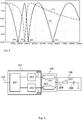
- FIG. 4 shows a frequency-voltage diagram with traces, as in an embodiment according to FIG. 2 and FIG. 3 may occur.
- the dashed curve 401 results in ideal conditions of an arrangement according to FIG. 2 without the electrical line 309.
- the solid curve 402 shows the detected AC voltage amplitude of an arrangement according to FIG. 3 with an exemplary length of electrical wire 309 of 60cm. From the previously a series resonance 403 of the resonance measuring probe 106 are here several resonance points 404, 405, 406. This complicates the evaluation of the resonance and thus the determination of whether the limit level 104 has been exceeded considerably.
- FIG. 5 shows a block diagram of an inventive embodiment of a level switch 101.
- the connecting part 108 now contains a first line 501 and a second line 502 instead of a line.
- the first line 501 connects the output 204 of the AC voltage generator 202 to the input 205 of the probe 106, while the second line 502 connects the input 205 of the probe 106 to the input 206 of the AC voltage detector 203.
- An AC voltage that passes from the output 204 through the first line 501 is more or less reflected from the input 205 of the probe 106, depending on the frequency.
- the impedance of the input 205 of the probe 106 changes considerably in the region of the resonance, whereby an impedance matching between the first line 501 and the input 205 of the probe 106 is in principle impossible.
- the reflected alternating voltage runs back to the first line 501 back and thereby forms at the output 204 of the AC voltage generator 202 by superposition of forward and backward voltage as before additional resonance points.
- the AC voltage reflected at the input 205 of the probe 106 passes via the second line 502 to the input 206 of the AC voltage detector 203.
- Superimpositions with other voltages can not occur here, which is why the voltage to be observed there reflects only the resonance behavior of the probe 106.
- a prerequisite is that the AC voltage entering the input 206 of the AC voltage detector 203 is not reflected there. This is accomplished by impedance matching the input 206 of the AC voltage detector 203 to a line impedance of the second line 502.
- Such impedance matching may be accomplished by, for example, corresponding stubs or matching networks of L, T or Pi structure devices.
- An impedance matching is also necessary at the output 204 of the AC generator 202.
- an input impedance of the AC voltage generator 202 at the output 204 is adapted to a line impedance of the first line 501.
- the Impedance matching between the first and second line 501, 502 to the AC voltage generator 202 and the AC voltage detector 203 at its control and evaluation 107 facing end ensures that the AC voltages are not reflected multiple times and so additional resonances are prevented by superposition of the reflected AC voltage ,
Description
- Die vorliegende Erfindung betrifft ein Füllstandmessgerät gemäß dem Oberbegriff des Patentanspruchs 1.
- Füllstandmessgeräte und Verfahren zur Bestimmung des Füllstands eines Füll- oder Schüttgutes in einem Behälter sind aus dem Stand der Technik bekannt und werden beispielsweise eingesetzt um zu erfassen, ob sich ein Füllstand oberhalb oder unterhalb eines vordefinierten Befüllungszustands befindet. Solche Geräte werden oft auch als Füllstandgrenzschalter bezeichnet.
- Füllstandmessgeräte sind zum Beispiel aus
DE 30 44 353 A1 ,US 2009/151446 A1 ,DE 10 2009 060 742 A1 , undUS 3,140,608 bekannt. - Füllstandgrenzschalter können auf ganz unterschiedlichen physikalischen Prinzipien beruhen. Eines dieser Prinzipien ist die Auswertung einer Kapazität, welche sich zwischen einer Messelektrode und einer Referenzelektrode bildet, wobei das Füllgut bei Befüllung des Behälters einen Raum zwischen Referenz- und Messelektrode ausfüllt und dabei die durch diese gebildete Kapazität verändert. Zur Messung der füllstandabhängigen Kapazität gibt es wiederum mehrere unterschiedliche Verfahren. Ein Verfahren zur Bestimmung der Kapazität ist die Bildung eines elektrischen Resonanzkreises unter Einbeziehung der interessierenden Kapazität. Die Resonanzfrequenz des Resonanzkreises kennzeichnet dabei die Größe der zu messenden Kapazität.
- Der Resonanzkreis kann beispielsweise als Serienschwingkreis mit Serienschaltung einer Induktivität mit einer Kapazität ausgeführt sein.
- Ein anderes Prinzip für einen Füllstandgrenzschalter besteht in der Nutzung einer Leitungsresonanz. Eine als längliche Sonde ausgeführte Leitung erzeugt Reflexionen einer eingespeisten elektrischen Wechselspannung, woraus sich eine stehende Spannungswelle auf der Sonde bildet. Am Spannungs-Einspeisepunkt zeigt die dort messbare Spannung auf Grund der stehenden Welle ein resonantes Verhalten, wobei die Leitungslänge die Resonanzstellen bestimmt. Bei Kontakt der Leitungs-Sonde mit Füllgut ergeben sich durch Kapazitäten und /oder zusätzliche Reflexionen bedingt durch das Füllgut Veränderungen in der Frequenzlage der Resonanzstellen. Diese sind hinsichtlich einer Grenzstandmeldung auswertbar.
- Die Anregung eines elektrischen Resonanzkreises bedingt die Einspeisung eines Wechselspannungssignals über einen Wechselspannungsgenerator. Durch Veränderung der Frequenz des eingespeisten Signals lässt sich die Resonanzfrequenz auffinden. Sie ist gekennzeichnet entweder durch eine Spannungsüberhöhung oder ein Spannungsminimum. Die Detektion der Wechselspannungsamplitude über der Frequenz erlaubt so die Bestimmung der Resonanzstelle (n) .
- Einige Anwendungen dieser Prinzipien der Grenzstanddetektion von Füllgütern erfordern beispielsweise einen Einbau des Sensors von oben durch eine vorhandene Öffnung im Behälterdeckel. Soll gleichzeitig aber der Schaltpunkt des Grenzschalters nicht im oberen Bereich des Behälters, also in der Nähe der Behälterdecke, sondern weiter unten liegen, so muss die detektierende Elektrode oder Sonde über eine Verlängerung auf die gewünschte Behälterhöhe gebracht werden. Es ist dabei von Vorteil, wenn die Sensorelektronik außerhalb des Behälters, in diesem Fall also oberhalb des Behälterdeckels, angebracht werden kann. Dies hat zur Folge, dass die Sonde über eine Verlängerung von der Elektronik abgesetzt werden muss. Diese Absetzbarkeit ist ebenso erforderlich bei Anwendungen mit sehr hohen Temperaturen im Behälter, damit die Elektronik weiter entfernt von der Sonde und den dort herrschenden Temperaturen problemlos betrieben werden kann.
- Damit ergibt sich die Anforderung, dass eine Leitung zwischen der Elektronik mit dem Wechselspannungsgenerator und dem Wechselspannungsdetektor einerseits und der Grenzstand detektierenden Sonde mit dem elektrischen Resonanzkreis andererseits nötig ist, die diese beiden Komponenten verbindet. Die so eingefügte elektrische Leitung hat die Ausbildung von Leitungsresonanzen auf der Verbindungsleitung zur Folge. Diese Leitungsresonanzen entstehen zusätzlich zu den vom Messprinzip her gewollten und für die Funktion wichtigen Resonanzen der Sonde und können sich diesen störend überlagern. Besonders störend wirken Leitungsresonanzen dann, wenn sie im gleichen Frequenzbereich wie die Sondenresonanzen liegen.
- Im Stand der Technik wird daher darauf geachtet, dass die Leitungslänge der Verlängerungsleitung so kurz ist, dass deren niedrigste Resonanzfrequenz, also beispielsweise die A/4-Leitungsresonanz, noch deutlich über der Sondenresonanzfrequenz liegt.
- Im Hinblick auf Funktionssicherheit des Messprinzips auch bei Medienanhaftungen an der Sonde ist es vorteilhaft, möglichst hohe Resonanzfrequenzen der Sonde im Bereich von über 100 MHz zu wählen.
- Es ergibt sich damit ein Konflikt zwischen der Wahl der Sonden-Resonanzfrequenz und der möglichen Leitungslänge einer gewünschten Verlängerung zwischen Sonde und Elektronik. Bei bestehenden Geräten führt dies beispielsweise dazu, dass nur kurze Verlängerungen unter 50 cm angeboten werden können. Hier setzt die vorliegende Erfindung an.
- Es ist eine Aufgabe der Erfindung, ein Füllstandmessgerät, insbesondere einen Füllstandgrenzschalter, gemäß dem Stand der Technik zur Verfügung zu stellen, der eine räumliche Anordnung von Sonde und Elektronik mit einer möglichst großen Distanz erlaubt.
- Diese Aufgabe wird durch ein Füllstandmessgerät gemäß Patentanspruch 1 gelöst.
- Vorteilhafte Weiterbildungen sind Gegenstand abhängiger Patentansprüche.
- Ein erfindungsgemäßes Füllstandmessgerät weist eine Elektronik mit einem Signalgenerator zur Erzeugung einer Wechselspannungund einem Signaldetektor zur Erfassung einer an einer resonanten Messsonde mit einem Eingang reflektierten Wechselspannung sowie ein Verbindungselement auf, das die Elektronik elektrisch und mechanisch mit der Resonanz-Messsonde verbindet, und zeichnet sich dadurch aus, dass das Verbindungselement eine erste Verbindungsleitung, die den Signalgenerator mit dem Eingang der Messsonde verbindet, und eine zweite Verbindungsleitung, die den Eingang der Messsonde mit dem Signaldetektor verbindet, aufweist.
- Auf diese Weise wird verhindert, dass am Eingang des Wechselspannungsdetektors Überlagerungen der von dem Wechselspannungsgenerator ausgesendeten und der von der Sonde reflektierten Wechselspannung anliegen und so eine Detektion einer von der Messsonde erzeugten Resonanz erschwert oder verhindert wird.
- Die erste Verbindungsleitung verbindet den Wechselspannungsgenerator mit der Sonde und die zweite Verbindungsleitung die Sonde mit dem Wechselspannungsdetektor. Die Verbindungsleitungen und der Wechselspannungsgenerator bzw. der Wechselspannungsdetektor sind dabei vorteilhafterweise in Ihrer Impedanz möglichst gut aneinander angepasst. Insbesondere sind vorteilhafterweise eine Leitungsimpedanz der erste Verbindungsleitung und eine Eingangsimpedanz des Ausgangs des Wechselspannungsgenerators sowie eine Leitungsimpedanz der zweiten Verbindungsleitung und eine Eingangsimpedanz des Eingangs des Wechselspannungsdetektors aneinander angepasst. Auf diese Weise lässt sich zwar nicht grundsätzlich die Entstehung von Leitungsresonanzen auf der ersten Verbindungsleitung verhindern, aber der Wechselspannungsdetektor, der über die zweite Verbindungsleitung mit der Messsonde verbunden ist, detektiert diese nicht mehr.
- Idealer Weise sind die erste Verbindungsleitung und die Eingangsimpedanz des Signalgeneratorausgangs derart aneinander angepasst, dass ein Reflexionsfaktor für eine an den Ausgang des Signalgenerators zurücklaufende Wechselspannung minimiert wird, insbesondere null ist.
- Auf diese Weise werden Mehrfachreflexionen des von der Messsonde reflektierten und zum Wechselspannungsgenerator zurücklaufenden Wechselspannungssignals verhindert, sodass bereits auf diese Weise eine weitere Verbesserung des Messergebnisses erzielt werden kann.
- Ferner ist es vorteilhaft, wenn die zweite Verbindungsleitung und die Eingangsimpedanz des Signaldetektoreingangs derart aneinander angepasst sind, dass ein Reflexionsfaktor am Eingang des Signaldetektors minimiert wird, insbesondere null ist.
- Auf diese Weise wird verhindert, dass das von der Messsonde reflektierte und über die zweite Verbindungsleitung zu dem Wechselspannungsdetektor geleitete Wechselspannungssignal am Eingang des Wechselspannungsdetektors erneut reflektiert wird. Auf diese Weise werden Signalüberlagerungen und auch Mehrfachreflexionen auf der zweiten Verbindungsleitung verhindert.
- Die Erfindung wird nachfolgend anhand von Ausführungsbeispielen unter Bezugnahme auf die beigefügten Figuren detailliert erläutert. Es zeigen:
-
Figur 1 ein Anwendungsbeispiel für einen Füllstandgrenzschalter -
Figur 2 ein Blockschaltbild eines Füllstandgrenzschalters mit Auswertung des Resonanzverhaltens einer Sonde, -
Figur 3 ein Blockschaltbild eines Füllstandgrenzschalters gemäßFigur 2 mit abgesetzter Sonde entsprechend dem Stand der Technik, -
Figur 4 beispielhafte Resonanzkurven der Füllstandgrenzschalter ausFigur 2 und Figur 3 , -
Figur 5 ein Blockschaltbild eines Füllstandgrenzschalters gemäßFigur 2 mit abgesetzter Sonde. - Die Zeichnungen sind lediglich schematisch und nicht maßstabsgetreu. Gleiche Bezugszeichen beschreiben gleiche oder ähnliche Teile.
- In
Figur 1 ist ein Anwendungsbeispiel für ein Füllstandmessgerät 101 als Füllstandgrenzschalter bzw. Grenzstandsensor gezeigt, wobei der Füllstandgrenzschalter oberhalb einer Füllgutoberfläche 102 angeordnet ist. Das Füllgut befindet sich in einem Behälter 103. Übersteigt die Füllgutoberfläche 102 im Bereich des Messgeräts 101 ein bestimmtes Niveau 104, den sogenannten Grenzstand, soll das Gerät das Überschreiten dieses Grenzstands 104 signalisieren. Dazu ist das Gerät 101 über eine oder mehrere Leitungen 105 mit einer hier nicht dargestellten Anzeige- und/ oder Steuereinheit verbunden, die auf das Ausgabesignal des Grenzstandsensors 101 anspricht. Über die Leitung(en) 105 kann der Grenzstandsensor 101 auch mit elektrischer Energie versorgt werden. Alternativ kann im oder beim Messgerät eine Energiequelle und / oder ein Energiespeicher, beispielsweise in Form einer Batterie oder eines Akkus, vorhanden sein. Die Leitungen 105 könnten in diesem Fall ganz entfallen, wenn der Sensor 101 seine Information drahtlos zu einer geeigneten Gegenstelle übermittelt. - Der Füllstandgrenzschalter 101 besteht üblicherweise aus einem Messfühler, für den hier synonym auch der Begriff Sonde 106 verwendet wird, und einer Steuerungs- und Auswertelektronik 107. Die Sonde 106 befindet sich innerhalb des Behälters 103, so dass sie mit dem Füllgut in Kontakt kommen kann. Sie weist beispielsweise eine stabähnliche Form auf, deren vertikale Ausdehnung je nach Ausführung im Bereich zwischen einigen Millimetern und einigen Zentimetern liegt. Daran schließt sich ein ebenfalls stabförmiges Verbindungsteil 108 an, das der elektrischen und mechanischen Verbindung der Sonde 106 mit der Steuerungs- und Auswertelektronik 107 dient.
- Die Steuerungs- und Auswertelektronik 107 dagegen ist vorteilhafterweise außerhalb des Behälters 103 und innerhalb eines hier nicht weiter dargestellten schützenden Umgehäuses angebracht. Zwischen Steuerungs- und Auswertelektronik 107 und Sonde 106 befindet sich eine Prozessadaption 109, die die beiden Teile miteinander verbindet und die geeignete Montageverbindung mit einer Behälterdecke herstellt.
- Soll der Grenzstand 104 auf einem alternativen Behälterniveau 110 detektiert werden, so ist die Positionierung der Sonde 106 entsprechend zu modifizieren. Dies ist in
Figur 1 gestrichelt dargestellt. Die sensitive Sonde 106 befindet sich demnach weiter unten im Behälter 103, wodurch sich eine größere Distanz zwischen der Sonde 106 und der Steuerungs- und Auswertelektronik 107 ergibt, die vom Verbindungsteil 108 zu überbrücken ist. -
Figur 2 zeigt in einem elektrischen Blockschaltbild die Steuerungs- und Auswertelektronik 107 sowie die Sonde 106. Die Steuerungs- und Auswertelektronik 107 besteht aus einer Steuerungs- und Auswerteeinheit 201, die einzelne Messvorgänge initiiert und auswertet sowie das Messergebnis nach außen kommuniziert sowie einem Wechselspannungsgenerator 202 und einem Wechselspannungsdetektor 203, die beide mit der Steuerungs- und Auswerteeinheit 201 verbundenen sind. - Zur Durchführung eines einzelnen Messvorgangs steuert die Steuerungs- und Auswerteeinheit 201 den Wechselspannungsgenerator 202 an, so dass dieser an einem Ausgang 204 ein Wechselspannungssignal bereitstellt. Das Wechselspannungssignal muss zur Bestimmung einer Resonanzstelle in seiner Frequenz verändert werden. Der Ausgang 204 ist mit einem Eingang 205 der Sonde 106 verbunden. Ebenfalls mit dem Eingang 205 ist ein Eingang 206 des Wechselspannungsdetektors 203 verbunden. Der Wechselspannungsdetektor 203 erfasst die frequenzabhängige Wechselspannungsamplitude der am Verbindungsknoten der Ein-/Ausgänge 204, 205 und 206 anliegenden Wechselspannung und liefert diese an die Steuerungs- und Auswerteeinheit 201 zurück. Innerhalb der Steuerungs- und Auswerteeinheit 201 wird der Zusammenhang zwischen Wechselspanungsfrequenz und zugehöriger detektierter Amplitude aufbereitet und hinsichtlich der Resonanzstellen ausgewertet. Die Resonanzstelle wird bestimmt durch die Ausgestaltung der Sonde 106. Im dargestellten Ausführungsbeispiel ist die Sonde durch einen Serienschwingkreis, bestehend aus einer Induktivität 207 und einer schematisch angedeuteten Kapazität 208 ausgebildet. Die Kapazität 208 ergibt sich durch eine hier nicht näher dargestellte Elektrode innerhalb der Sonde 106, die mit der Umgebung einen Kondensator bildet. Eine Frequenz- und / oder Amplitudenverschiebung der Resonanzstelle deutet auf eine Kapazitätsbeeinflussung durch das Füllgut und damit eine Überschreitung des Grenzstands 104 hin. Alternativ zu einem Schwingkreis kann auch die Resonanz einer Sondenleitung zur Bestimmung des Grenzstands 104 genutzt werden.
-
Figur 3 entspricht weitgehend dem Blockschaltbild ausFigur 2 mit dem Unterschied, dass der Sondeneingang 205 vom Verbindungknoten zwischen den Ein-/Ausgängen 204 , 205 von Wechselspannungsgenerator 202 und Wechselspannungsdetektor 203 weiter entfernt ist. Das Verbindungsteil 108 verbindet die Teile und enthält eine elektrische Leitung 309. Die elektrische Leitung 309 kann beispielsweise als eine Koaxialleitung, eine Zweidrahtleitung, eine Eindrahtleitung oder eine Microstripleitung ausgebildet sein. Eine Leitungslänge richtet sich wie bereits beschrieben nach der zu überbrückenden Distanz zwischen der Sonde 106 und der Steuerungs- und Auswertelektronik 107. -
Figur 3 zeigt eine Ausgestaltung, wie diese im Stand der Technik bislang üblich ist. Diese Lösung, bei der lediglich eine elektrische Leitung 309 zwischen der Sonde 106 und dem Verbindungsknoten der Ein-/Ausgänge 204, 206 vorgesehen ist, hat den Nachteil, dass innerhalb der elektrischen Leitung 309 zusätzliche Resonanzen auftreten, die von der Leitungslänge abhängig sind. Diese zusätzlichen Resonanzen können eine von der Sonde 106 her rührende Resonanz zur Detektion des Grenzstandes 104 derart überlagern, dass eine Messung nicht oder nur sehr unzuverlässig möglich ist. -
Figur 4 zeigt ein Frequenz-Spannungs-Diagramm mit Messkurven, wie sie bei einer Ausgestaltung gemäßFigur 2 und Figur 3 auftreten können. Die gestrichelte Kurve 401 ergibt sich bei idealen Verhältnissen einer Anordnung gemäßFigur 2 ohne die elektrische Leitung 309. Die durchgezogene Kurve 402 dagegen zeigt die detektierte Wechselspannungsamplitude einer Anordnung gemäßFigur 3 mit einer beispielhaften Länge der elektrischen Leitung 309 von 60cm. Aus der zuvor einen Serienresonanz 403 der Resonanz-Messsonde 106 werden hier mehrere Resonanzstellen 404, 405, 406. Dies erschwert die Auswertung der Resonanz und damit die Bestimmung, ob der Grenzstand 104 überschritten wurde, erheblich. -
Figur 5 zeigt ein Blockschaltbild einer erfindungsgemäßen Ausgestaltung eines Grenzstandschalters 101. Der Verbindungsteil 108 enthält nun statt einer Leitung eine erste Leitung 501 und eine zweite Leitung 502. Die erste Leitung 501 verbindet den Ausgang 204 des Wechselspannungsgenerators 202 mit dem Eingang 205 der Sonde 106, während die zweite Leitung 502 den Eingang 205 der Sonde 106 mit dem Eingang 206 des Wechselspannungsdetektors 203 verbindet. Eine Wechselspannung, die vom Ausgang 204 kommend durch die erste Leitung 501 läuft, wird je nach Frequenz mehr oder weniger vom Eingang 205 der Sonde 106 reflektiert. Die Impedanz des Eingangs 205 der Sonde 106 ändert sich im Bereich der Resonanz beträchtlich, wodurch eine Impedanzanpassung zwischen der ersten Leitung 501 und dem Eingang 205 der Sonde 106 prinzipiell unmöglich ist. - Die reflektierte Wechselspannung läuft zum einen die erste Leitung 501 wieder zurück und bildet dadurch am Ausgang 204 des Wechselspannungsgenerators 202 durch Überlagerung von vor- und rücklaufender Spannung nach wie vor zusätzliche Resonanzstellen. Zum anderen läuft die am Eingang 205 der Sonde 106 reflektierte Wechselspannung über die zweite Leitung 502 zum Eingang 206 des Wechselspannungsdetektors 203. Hier kann es nicht zu Überlagerungen mit anderen Spannungen kommen, weshalb die dort zu beobachtende Spannung nur das Resonanzverhalten der Sonde 106 wiedergibt. Voraussetzung ist allerdings dass die in den Eingang 206 des Wechselspannungsdetektors 203 einlaufende Wechselspannung dort nicht reflektiert wird. Dies erreicht man durch eine Impedanzanpassung des Eingangs 206 des Wechselspannungsdetektors 203 an eine Leitungsimpedanz der zweiten Leitung 502. Eine solche Impedanzanpassung kann beispielsweise durch entsprechende Stichleitungen oder AnpassNetzwerke von Bauelementen in L-, T- oder Pi-Struktur erfolgen.
- Eine Impedanzanpassung ist außerdem am Ausgang 204 des Wechselspannungsgenerators 202 notwendig. Dazu ist eine Eingangsimpedanz des Wechselspannungsgenerators 202 am Ausgang 204 an eine Leitungsimpedanz der ersten Leitung 501 anzupassen. Die Impedanzanpassung zwischen der ersten und zweiten Leitung 501, 502 an den Wechselspannungsgenerator 202 bzw. den Wechselspannungsdetektor 203 an ihrem der Steuerungs- und Auswertelektronik 107 zugewandten Ende sorgt dafür, dass die Wechselspannungen nicht mehrfach reflektiert werden und so zusätzliche Resonanzen durch Überlagerung der reflektierten Wechselspannung verhindert werden.
-
- 101
- Füllstandmessgerät
- 102
- Füllgutoberfläche
- 103
- Behälter
- 104
- Niveau, erstes
- 105
- Leitung
- 106
- Sonde, Messsonde, Messfühler
- 107
- Auswerteelement, Steuerungs- und Auswerteelektronik
- 108
- Verbindungsteil, Verbindungselement
- 109
- Prozessadaption
- 110
- Niveau, zweites
- 201
- Steuerungs- und Auswerteeinheit
- 202
- Wechselspannungsgenerator, Signalgenerator
- 203
- Wechselspannungsdetektor, Signaldetektor
- 204
- Generatorausgang
- 205
- Sondeneingang
- 206
- Detektoreingang
- 207
- Induktivität
- 208
- Kapazität
- 309
- Verbindungsleitung
- 401
- Kurve, erste
- 402
- Kurve, zweite
- 403
- Resonanzstelle, Serienresonanz der Messsonde
- 404
- Resonanzstelle
- 405
- Resonanzstelle
- 406
- Resonanzstelle
- 501
- erste Verbindungsleitung
- 502
- zweite Verbindungsleitung
- λ
- Wellenlänge
Claims (10)
- Füllstandmessgerät (101) mit einer Steuerungs- und Auswerteelektronik (107) mit einem Signalgenerator (202) zur Erzeugung einer Wechselspannung, einem Signaldetektor (203) zur Erfassung einer an einem Eingang (205) einer resonanten Messsonde (106) reflektierten Wechselspannung, der resonanten Messsonde (106) mit dem Eingang (205), und einem Verbindungselement (108), das die Steuerungs- und Auswerteelektronik (107) elektrisch und mechanisch mit der Messsonde (106) verbindet,
dadurch gekennzeichnet, dass das Verbindungselement (108) eine erste Verbindungsleitung (501), die den Signalgenerator (202) mit dem Eingang (205) der Messsonde (106) verbindet, und eine zweite Verbindungsleitung (502), die den Eingang (205) der Messsonde (106) mit dem Signaldetektor (203) verbindet, aufweist. - Füllstandmessgerät (101) gemäß Anspruch 1,
dadurch gekennzeichnet, dass eine erste Impedanz der ersten Verbindungsleitung (501) und eine Eingangsimpedanz des Ausgangs (204) des Signalgenerators (202) aneinander angepasst sind und/oder eine zweite Impedanz der zweiten Verbindungsleitung (502) und eine Eingangsimpedanz des Eingangs (206) des Signaldetektors (203) aneinander angepasst sind. - Füllstandmessgerät (101) gemäß Anspruch 2,
dadurch gekennzeichnet, dass die erste Verbindungsleitung (501) und die Eingangsimpedanz des Signalgenerators (202) derart aneinander angepasst sind, dass ein Reflexionsfaktor am Eingang des Signalgenerators (202) minimiert wird, insbesondere null ist. - Füllstandmessgerät (101) gemäß Anspruch 2 oder 3,
dadurch gekennzeichnet, dass die zweite Verbindungsleitung (502) und die Eingangsimpedanz des Signaldetektors (203) derart aneinander angepasst sind, dass ein Reflexionsfaktor am Eingang des Signaldetektors (203) minimiert wird, insbesondere null ist. - Füllstandmessgerät (101) gemäß einem der Ansprüche 3 oder 4,
dadurch gekennzeichnet, dass die Anpassung durch Auswahl geeigneter, insbesondere standardisierter, Verbindungsleitungen (501, 502) mit einer vorbestimmten Leitungsimpedanz von insbesondere 50 Ohm oder 75 Ohm, sowie durch Anpassung der Eingangsimpedanz von Signalgenerator (202) und Signaldetektor (203) durch Impedanz-Anpassnetzwerke, insbesondere in L-, T- oder Pi-Struktur, oder Leitungselementen, insbesondere durch Stichleitungen, erfolgt. - Füllstandmessgerät (101) nach einem der vorhergehenden Ansprüche,
dadurch gekennzeichnet, dass die erste Verbindungsleitung (501) und/oder die zweite Verbindungsleitung (502) als Koaxialleitung, Zweidrahtleitung oder Streifenleitung, insbesondere als Mikrostreifenleitung, ausgebildet sind. - Füllstandmessgerät (101) gemäß einem der vorhergehenden Ansprüche,
dadurch gekennzeichnet, dass das Füllstandmessgerät (101) als Füllstandgrenzschalter ausgebildet ist. - Füllstandmessgerät (101) gemäß einem der vorhergehenden Ansprüche,
dadurch gekennzeichnet, dass eine Länge der Verbindungsleitungen (501, 502) wenigstens 50 cm, bevorzugt wenigstens 80 cm, weiter bevorzugt wenigstens 120 cm beträgt. - Füllstandmessgerät (101) gemäß einem der vorhergehenden Ansprüche,
dadurch gekennzeichnet, dass eine Länge der Verbindungsleitungen (501, 502) wenigstens ein Viertel einer Wellenlänge der Resonanzfrequenz der Messsonde (106) beträgt. - Füllstandmessgerät (101) gemäß einem der vorhergehenden Ansprüche,
dadurch gekennzeichnet, dass eine Resonanzfrequenz der Messsonde (106) wenigstens 10 MHz, bevorzugt wenigstens 50 MHz, weiter bevorzugt wenigstens 100 MHz beträgt.
Priority Applications (4)
| Application Number | Priority Date | Filing Date | Title |
|---|---|---|---|
| HUE15176941A HUE040669T2 (hu) | 2015-07-15 | 2015-07-15 | Töltésszintmérõ készülék |
| EP15176941.1A EP3118591B1 (de) | 2015-07-15 | 2015-07-15 | Füllstandmessgerät |
| US15/157,638 US10145718B2 (en) | 2015-07-15 | 2016-05-18 | Level gauge |
| CN201610471759.7A CN106352946B (zh) | 2015-07-15 | 2016-06-24 | 物位测量设备 |
Applications Claiming Priority (1)
| Application Number | Priority Date | Filing Date | Title |
|---|---|---|---|
| EP15176941.1A EP3118591B1 (de) | 2015-07-15 | 2015-07-15 | Füllstandmessgerät |
Publications (2)
| Publication Number | Publication Date |
|---|---|
| EP3118591A1 EP3118591A1 (de) | 2017-01-18 |
| EP3118591B1 true EP3118591B1 (de) | 2018-09-12 |
Family
ID=53716349
Family Applications (1)
| Application Number | Title | Priority Date | Filing Date |
|---|---|---|---|
| EP15176941.1A Active EP3118591B1 (de) | 2015-07-15 | 2015-07-15 | Füllstandmessgerät |
Country Status (4)
| Country | Link |
|---|---|
| US (1) | US10145718B2 (de) |
| EP (1) | EP3118591B1 (de) |
| CN (1) | CN106352946B (de) |
| HU (1) | HUE040669T2 (de) |
Families Citing this family (4)
| Publication number | Priority date | Publication date | Assignee | Title |
|---|---|---|---|---|
| GB2569540A (en) | 2017-12-19 | 2019-06-26 | Rosemount Measurement Ltd | Improvements in or relating to interface detection |
| HUE051101T2 (hu) | 2018-03-22 | 2021-03-01 | Grieshaber Vega Kg | Impedancia-határértékkapcsoló EMC sugárzás csökkentésére és eljárás egy közeg határértékének meghatározására egy impedancia-határértékkapcsolóval |
| EP3605029B1 (de) * | 2018-07-30 | 2020-09-16 | VEGA Grieshaber KG | Verfahren zum bestimmen eines schaltzustands eines impedanzsensors und impedanzsensor |
| HUE054809T2 (hu) * | 2018-07-30 | 2021-09-28 | Grieshaber Vega Kg | Eljárás egy impedanciaérzékelõ kapcsolási állapotának meghatározására és impedanciaérzékelõ |
Citations (1)
| Publication number | Priority date | Publication date | Assignee | Title |
|---|---|---|---|---|
| US3140608A (en) * | 1960-12-16 | 1964-07-14 | Brooks Equipment Corp | Liquid level gauge |
Family Cites Families (21)
| Publication number | Priority date | Publication date | Assignee | Title |
|---|---|---|---|---|
| DE3044353C2 (de) * | 1980-11-25 | 1986-01-09 | Endress U. Hauser Gmbh U. Co, 7867 Maulburg | Vorrichtung zur Feststellung des Erreichens eines vorbestimmten Füllstandes in einem Behälter |
| DE19749884C1 (de) * | 1997-11-12 | 1999-08-19 | Rechner Ind Elektronik Gmbh | Schaltungsanordnung zur linearen, materialunabhängigen kapazitiven Standmessung |
| JP4497637B2 (ja) * | 1999-11-01 | 2010-07-07 | 株式会社ノーケン | 静電容量式検知装置 |
| US6750657B2 (en) * | 2000-11-23 | 2004-06-15 | Vega Grieshaber Kg | Combination of a feedthrough element for an electric high-frequency signal and a probe, and a level meter metering device including a combination of this type |
| JP2007318585A (ja) * | 2006-05-29 | 2007-12-06 | Alps Electric Co Ltd | デジタル信号受信装置 |
| CN100486812C (zh) * | 2006-12-20 | 2009-05-13 | 珠海天威技术开发有限公司 | 检测电路及墨盒 |
| US7538630B2 (en) * | 2006-12-27 | 2009-05-26 | Fujitsu Media Devices Limited | Voltage controlled oscillator |
| DE102007004693A1 (de) * | 2007-01-25 | 2008-07-31 | Abertax Research And Development Ltd. | Resonanzsensor-Einrichtung zur Ermittlung eines Flüssigkeitspegels |
| US7525476B1 (en) * | 2007-11-13 | 2009-04-28 | Rosemount Tank Radar Ab | System and method for filling level determination |
| US7634945B2 (en) * | 2007-12-13 | 2009-12-22 | Robertshaw Controls Company | Apparatus to water detection in a storage tank |
| CN100575890C (zh) * | 2008-09-10 | 2009-12-30 | 南京林业大学 | 电容式液位传感器及应用该传感器的液位检测装置 |
| US8018373B2 (en) * | 2008-12-19 | 2011-09-13 | Rosemount Tank Radar Ab | System and method for filling level determination |
| US7855676B2 (en) * | 2009-03-10 | 2010-12-21 | Rosemount Tank Radar Ab | Radar level gauge system with leakage detection |
| DE102009060742A1 (de) * | 2009-12-30 | 2011-07-07 | NEGELE Messtechnik GmbH, 87743 | Einrichtung zum Erkennen eines Pegelstandes |
| EP2490040B1 (de) * | 2011-02-17 | 2016-08-17 | Rosemount Tank Radar AB | Einzelleitersonde-GWR-System mit reduzierter Reflexion am Düsenende |
| JP5759751B2 (ja) * | 2011-02-28 | 2015-08-05 | 株式会社生体分子計測研究所 | 走査型トンネル顕微鏡およびこれを用いたナノスケール表面観察法 |
| GB201203205D0 (en) * | 2012-02-24 | 2012-04-11 | Mobrey Ltd | Improvements in or relating to interface detection |
| CN103063274B (zh) * | 2012-12-25 | 2015-01-21 | 天津大学 | 压电换能器井下液位测量仪 |
| CN203811238U (zh) * | 2014-01-20 | 2014-09-03 | 深圳市华儒科技有限公司 | 一种信号调理器及物位测量系统 |
| US9304029B2 (en) * | 2014-03-31 | 2016-04-05 | Rosemount Tank Radar Ab | Level gauging system for long narrow nozzles |
| US9778089B2 (en) * | 2014-06-30 | 2017-10-03 | Rosemount Tank Radar Ab | Multi-channel guided wave radar level gauge |
-
2015
- 2015-07-15 EP EP15176941.1A patent/EP3118591B1/de active Active
- 2015-07-15 HU HUE15176941A patent/HUE040669T2/hu unknown
-
2016
- 2016-05-18 US US15/157,638 patent/US10145718B2/en active Active
- 2016-06-24 CN CN201610471759.7A patent/CN106352946B/zh active Active
Patent Citations (1)
| Publication number | Priority date | Publication date | Assignee | Title |
|---|---|---|---|---|
| US3140608A (en) * | 1960-12-16 | 1964-07-14 | Brooks Equipment Corp | Liquid level gauge |
Also Published As
| Publication number | Publication date |
|---|---|
| US20170356784A1 (en) | 2017-12-14 |
| EP3118591A1 (de) | 2017-01-18 |
| US10145718B2 (en) | 2018-12-04 |
| CN106352946A (zh) | 2017-01-25 |
| CN106352946B (zh) | 2020-08-07 |
| HUE040669T2 (hu) | 2019-03-28 |
Similar Documents
| Publication | Publication Date | Title |
|---|---|---|
| EP3118591B1 (de) | Füllstandmessgerät | |
| EP1204848B1 (de) | Verfahren zur füllstandsmessung und füllstandssensor | |
| EP2962074B1 (de) | Verfahren und vorrichtung zur überwachung eines vorgegebenen füllstands eines mediums in einem behälter | |
| DE112018005213T5 (de) | System zur Handerkennung auf einem Lenkrad | |
| EP2758789B1 (de) | Vorrichtung zur messung eines batteriestroms | |
| EP3390981B1 (de) | Sensoradapter | |
| EP3124314B1 (de) | Fremdobjekterkennung, insbesondere für induktive ladesysteme | |
| DE112013006074T5 (de) | Kapazitiver Sensor, der dafür ausgelegt ist, ein Heizelement als Antennenelektrode zu verwenden | |
| EP2909902A1 (de) | Leiterdetektion bei einem kabelabisolierprozess | |
| EP3006905B1 (de) | Verfahren sowie vorrichtung zur füllstandsmessung | |
| DE102011078369B4 (de) | Kapazitive Sensoreinrichtung sowie Verfahren zum Kalibrieren einer kapazitiven Sensoreinrichtung | |
| EP3740741B1 (de) | Sondeneinheit | |
| EP3153829B1 (de) | Verfahren und vorrichtung zur grenzstandbestimmung | |
| DE102007003887A1 (de) | Verfahren zur Bedienung einer Vorrichtung zur kapazitiven Bestimmung und/oder Überwachung einer Prozessgröße | |
| DE4312813C2 (de) | Anordnung zur kapazitiven Füllstandsmessung | |
| DE60105839T2 (de) | Berührungslose messmethode und -vorrichtung zur erzeugung eines signals, das einem abstand zwischen gegenüberliegenden oberflächen entspricht | |
| DE102017115516A1 (de) | Kapazitives Füllstandsmessgerät | |
| WO2020020534A1 (de) | Überprüfung der qualität einer fluidkonzentration | |
| EP3631381A1 (de) | Verfahren zur prozessüberwachung | |
| EP3357742A1 (de) | Einrichtung zum erfassen von objekten insbesondere für ladesysteme | |
| EP3671196B1 (de) | System zur ermittlung eines alterungszustands eines elastomerprodukts | |
| EP0185255A1 (de) | Verfahren zur Polaritätserkennung von elektronischen Bauteilen und Anordnung zur Durchführung des Verfahrens | |
| EP3567349B1 (de) | Impedanzgrenzschalter mit anpassung der anregung | |
| EP3583257A1 (de) | Verfahren zum betreiben einer karde sowie karde | |
| EP3724624B1 (de) | Vorrichtung zur bestimmung und/oder überwachung einer temperatur |
Legal Events
| Date | Code | Title | Description |
|---|---|---|---|
| STAA | Information on the status of an ep patent application or granted ep patent |
Free format text: STATUS: EXAMINATION IS IN PROGRESS |
|
| PUAI | Public reference made under article 153(3) epc to a published international application that has entered the european phase |
Free format text: ORIGINAL CODE: 0009012 |
|
| 17P | Request for examination filed |
Effective date: 20160817 |
|
| AK | Designated contracting states |
Kind code of ref document: A1 Designated state(s): AL AT BE BG CH CY CZ DE DK EE ES FI FR GB GR HR HU IE IS IT LI LT LU LV MC MK MT NL NO PL PT RO RS SE SI SK SM TR |
|
| AX | Request for extension of the european patent |
Extension state: BA ME |
|
| RBV | Designated contracting states (corrected) |
Designated state(s): AL AT BE BG CH CY CZ DE DK EE ES FI FR GB GR HR HU IE IS IT LI LT LU LV MC MK MT NL NO PL PT RO RS SE SI SK SM TR |
|
| GRAP | Despatch of communication of intention to grant a patent |
Free format text: ORIGINAL CODE: EPIDOSNIGR1 |
|
| STAA | Information on the status of an ep patent application or granted ep patent |
Free format text: STATUS: GRANT OF PATENT IS INTENDED |
|
| RIC1 | Information provided on ipc code assigned before grant |
Ipc: G01F 23/28 20060101ALI20180403BHEP Ipc: G01F 23/26 20060101AFI20180403BHEP |
|
| INTG | Intention to grant announced |
Effective date: 20180426 |
|
| GRAS | Grant fee paid |
Free format text: ORIGINAL CODE: EPIDOSNIGR3 |
|
| GRAA | (expected) grant |
Free format text: ORIGINAL CODE: 0009210 |
|
| STAA | Information on the status of an ep patent application or granted ep patent |
Free format text: STATUS: THE PATENT HAS BEEN GRANTED |
|
| AK | Designated contracting states |
Kind code of ref document: B1 Designated state(s): AL AT BE BG CH CY CZ DE DK EE ES FI FR GB GR HR HU IE IS IT LI LT LU LV MC MK MT NL NO PL PT RO RS SE SI SK SM TR |
|
| REG | Reference to a national code |
Ref country code: GB Ref legal event code: FG4D Free format text: NOT ENGLISH |
|
| REG | Reference to a national code |
Ref country code: CH Ref legal event code: EP |
|
| REG | Reference to a national code |
Ref country code: IE Ref legal event code: FG4D Free format text: LANGUAGE OF EP DOCUMENT: GERMAN |
|
| REG | Reference to a national code |
Ref country code: DE Ref legal event code: R096 Ref document number: 502015005801 Country of ref document: DE |
|
| REG | Reference to a national code |
Ref country code: AT Ref legal event code: REF Ref document number: 1041165 Country of ref document: AT Kind code of ref document: T Effective date: 20181015 |
|
| REG | Reference to a national code |
Ref country code: SE Ref legal event code: TRGR |
|
| REG | Reference to a national code |
Ref country code: NL Ref legal event code: MP Effective date: 20180912 |
|
| REG | Reference to a national code |
Ref country code: LT Ref legal event code: MG4D |
|
| PG25 | Lapsed in a contracting state [announced via postgrant information from national office to epo] |
Ref country code: BG Free format text: LAPSE BECAUSE OF FAILURE TO SUBMIT A TRANSLATION OF THE DESCRIPTION OR TO PAY THE FEE WITHIN THE PRESCRIBED TIME-LIMIT Effective date: 20181212 Ref country code: LT Free format text: LAPSE BECAUSE OF FAILURE TO SUBMIT A TRANSLATION OF THE DESCRIPTION OR TO PAY THE FEE WITHIN THE PRESCRIBED TIME-LIMIT Effective date: 20180912 Ref country code: NO Free format text: LAPSE BECAUSE OF FAILURE TO SUBMIT A TRANSLATION OF THE DESCRIPTION OR TO PAY THE FEE WITHIN THE PRESCRIBED TIME-LIMIT Effective date: 20181212 Ref country code: FI Free format text: LAPSE BECAUSE OF FAILURE TO SUBMIT A TRANSLATION OF THE DESCRIPTION OR TO PAY THE FEE WITHIN THE PRESCRIBED TIME-LIMIT Effective date: 20180912 Ref country code: RS Free format text: LAPSE BECAUSE OF FAILURE TO SUBMIT A TRANSLATION OF THE DESCRIPTION OR TO PAY THE FEE WITHIN THE PRESCRIBED TIME-LIMIT Effective date: 20180912 Ref country code: GR Free format text: LAPSE BECAUSE OF FAILURE TO SUBMIT A TRANSLATION OF THE DESCRIPTION OR TO PAY THE FEE WITHIN THE PRESCRIBED TIME-LIMIT Effective date: 20181213 |
|
| PG25 | Lapsed in a contracting state [announced via postgrant information from national office to epo] |
Ref country code: HR Free format text: LAPSE BECAUSE OF FAILURE TO SUBMIT A TRANSLATION OF THE DESCRIPTION OR TO PAY THE FEE WITHIN THE PRESCRIBED TIME-LIMIT Effective date: 20180912 Ref country code: LV Free format text: LAPSE BECAUSE OF FAILURE TO SUBMIT A TRANSLATION OF THE DESCRIPTION OR TO PAY THE FEE WITHIN THE PRESCRIBED TIME-LIMIT Effective date: 20180912 Ref country code: AL Free format text: LAPSE BECAUSE OF FAILURE TO SUBMIT A TRANSLATION OF THE DESCRIPTION OR TO PAY THE FEE WITHIN THE PRESCRIBED TIME-LIMIT Effective date: 20180912 |
|
| REG | Reference to a national code |
Ref country code: HU Ref legal event code: AG4A Ref document number: E040669 Country of ref document: HU |
|
| PG25 | Lapsed in a contracting state [announced via postgrant information from national office to epo] |
Ref country code: NL Free format text: LAPSE BECAUSE OF FAILURE TO SUBMIT A TRANSLATION OF THE DESCRIPTION OR TO PAY THE FEE WITHIN THE PRESCRIBED TIME-LIMIT Effective date: 20180912 Ref country code: EE Free format text: LAPSE BECAUSE OF FAILURE TO SUBMIT A TRANSLATION OF THE DESCRIPTION OR TO PAY THE FEE WITHIN THE PRESCRIBED TIME-LIMIT Effective date: 20180912 Ref country code: IT Free format text: LAPSE BECAUSE OF FAILURE TO SUBMIT A TRANSLATION OF THE DESCRIPTION OR TO PAY THE FEE WITHIN THE PRESCRIBED TIME-LIMIT Effective date: 20180912 Ref country code: RO Free format text: LAPSE BECAUSE OF FAILURE TO SUBMIT A TRANSLATION OF THE DESCRIPTION OR TO PAY THE FEE WITHIN THE PRESCRIBED TIME-LIMIT Effective date: 20180912 Ref country code: ES Free format text: LAPSE BECAUSE OF FAILURE TO SUBMIT A TRANSLATION OF THE DESCRIPTION OR TO PAY THE FEE WITHIN THE PRESCRIBED TIME-LIMIT Effective date: 20180912 Ref country code: IS Free format text: LAPSE BECAUSE OF FAILURE TO SUBMIT A TRANSLATION OF THE DESCRIPTION OR TO PAY THE FEE WITHIN THE PRESCRIBED TIME-LIMIT Effective date: 20190112 Ref country code: PL Free format text: LAPSE BECAUSE OF FAILURE TO SUBMIT A TRANSLATION OF THE DESCRIPTION OR TO PAY THE FEE WITHIN THE PRESCRIBED TIME-LIMIT Effective date: 20180912 |
|
| PG25 | Lapsed in a contracting state [announced via postgrant information from national office to epo] |
Ref country code: PT Free format text: LAPSE BECAUSE OF FAILURE TO SUBMIT A TRANSLATION OF THE DESCRIPTION OR TO PAY THE FEE WITHIN THE PRESCRIBED TIME-LIMIT Effective date: 20190112 Ref country code: SK Free format text: LAPSE BECAUSE OF FAILURE TO SUBMIT A TRANSLATION OF THE DESCRIPTION OR TO PAY THE FEE WITHIN THE PRESCRIBED TIME-LIMIT Effective date: 20180912 Ref country code: SM Free format text: LAPSE BECAUSE OF FAILURE TO SUBMIT A TRANSLATION OF THE DESCRIPTION OR TO PAY THE FEE WITHIN THE PRESCRIBED TIME-LIMIT Effective date: 20180912 |
|
| REG | Reference to a national code |
Ref country code: DE Ref legal event code: R097 Ref document number: 502015005801 Country of ref document: DE |
|
| PLBE | No opposition filed within time limit |
Free format text: ORIGINAL CODE: 0009261 |
|
| STAA | Information on the status of an ep patent application or granted ep patent |
Free format text: STATUS: NO OPPOSITION FILED WITHIN TIME LIMIT |
|
| PG25 | Lapsed in a contracting state [announced via postgrant information from national office to epo] |
Ref country code: DK Free format text: LAPSE BECAUSE OF FAILURE TO SUBMIT A TRANSLATION OF THE DESCRIPTION OR TO PAY THE FEE WITHIN THE PRESCRIBED TIME-LIMIT Effective date: 20180912 |
|
| 26N | No opposition filed |
Effective date: 20190613 |
|
| PG25 | Lapsed in a contracting state [announced via postgrant information from national office to epo] |
Ref country code: SI Free format text: LAPSE BECAUSE OF FAILURE TO SUBMIT A TRANSLATION OF THE DESCRIPTION OR TO PAY THE FEE WITHIN THE PRESCRIBED TIME-LIMIT Effective date: 20180912 |
|
| PG25 | Lapsed in a contracting state [announced via postgrant information from national office to epo] |
Ref country code: MC Free format text: LAPSE BECAUSE OF FAILURE TO SUBMIT A TRANSLATION OF THE DESCRIPTION OR TO PAY THE FEE WITHIN THE PRESCRIBED TIME-LIMIT Effective date: 20180912 |
|
| PG25 | Lapsed in a contracting state [announced via postgrant information from national office to epo] |
Ref country code: TR Free format text: LAPSE BECAUSE OF FAILURE TO SUBMIT A TRANSLATION OF THE DESCRIPTION OR TO PAY THE FEE WITHIN THE PRESCRIBED TIME-LIMIT Effective date: 20180912 |
|
| REG | Reference to a national code |
Ref country code: BE Ref legal event code: MM Effective date: 20190731 |
|
| PG25 | Lapsed in a contracting state [announced via postgrant information from national office to epo] |
Ref country code: LU Free format text: LAPSE BECAUSE OF NON-PAYMENT OF DUE FEES Effective date: 20190715 Ref country code: BE Free format text: LAPSE BECAUSE OF NON-PAYMENT OF DUE FEES Effective date: 20190731 |
|
| PG25 | Lapsed in a contracting state [announced via postgrant information from national office to epo] |
Ref country code: IE Free format text: LAPSE BECAUSE OF NON-PAYMENT OF DUE FEES Effective date: 20190715 |
|
| PG25 | Lapsed in a contracting state [announced via postgrant information from national office to epo] |
Ref country code: CY Free format text: LAPSE BECAUSE OF FAILURE TO SUBMIT A TRANSLATION OF THE DESCRIPTION OR TO PAY THE FEE WITHIN THE PRESCRIBED TIME-LIMIT Effective date: 20180912 |
|
| PG25 | Lapsed in a contracting state [announced via postgrant information from national office to epo] |
Ref country code: MT Free format text: LAPSE BECAUSE OF FAILURE TO SUBMIT A TRANSLATION OF THE DESCRIPTION OR TO PAY THE FEE WITHIN THE PRESCRIBED TIME-LIMIT Effective date: 20180912 |
|
| REG | Reference to a national code |
Ref country code: AT Ref legal event code: MM01 Ref document number: 1041165 Country of ref document: AT Kind code of ref document: T Effective date: 20200715 |
|
| PG25 | Lapsed in a contracting state [announced via postgrant information from national office to epo] |
Ref country code: AT Free format text: LAPSE BECAUSE OF NON-PAYMENT OF DUE FEES Effective date: 20200715 |
|
| PG25 | Lapsed in a contracting state [announced via postgrant information from national office to epo] |
Ref country code: MK Free format text: LAPSE BECAUSE OF FAILURE TO SUBMIT A TRANSLATION OF THE DESCRIPTION OR TO PAY THE FEE WITHIN THE PRESCRIBED TIME-LIMIT Effective date: 20180912 |
|
| P01 | Opt-out of the competence of the unified patent court (upc) registered |
Effective date: 20230626 |
|
| PGFP | Annual fee paid to national office [announced via postgrant information from national office to epo] |
Ref country code: GB Payment date: 20230724 Year of fee payment: 9 Ref country code: CZ Payment date: 20230707 Year of fee payment: 9 Ref country code: CH Payment date: 20230801 Year of fee payment: 9 |
|
| PGFP | Annual fee paid to national office [announced via postgrant information from national office to epo] |
Ref country code: SE Payment date: 20230724 Year of fee payment: 9 Ref country code: HU Payment date: 20230710 Year of fee payment: 9 Ref country code: FR Payment date: 20230724 Year of fee payment: 9 Ref country code: DE Payment date: 20230720 Year of fee payment: 9 |