EP3118582A1 - Feedback control device - Google Patents
Feedback control device Download PDFInfo
- Publication number
- EP3118582A1 EP3118582A1 EP16179197.5A EP16179197A EP3118582A1 EP 3118582 A1 EP3118582 A1 EP 3118582A1 EP 16179197 A EP16179197 A EP 16179197A EP 3118582 A1 EP3118582 A1 EP 3118582A1
- Authority
- EP
- European Patent Office
- Prior art keywords
- electric current
- detection
- sensor
- detection system
- motor
- Prior art date
- Legal status (The legal status is an assumption and is not a legal conclusion. Google has not performed a legal analysis and makes no representation as to the accuracy of the status listed.)
- Granted
Links
Images



Classifications
-
- H—ELECTRICITY
- H02—GENERATION; CONVERSION OR DISTRIBUTION OF ELECTRIC POWER
- H02P—CONTROL OR REGULATION OF ELECTRIC MOTORS, ELECTRIC GENERATORS OR DYNAMO-ELECTRIC CONVERTERS; CONTROLLING TRANSFORMERS, REACTORS OR CHOKE COILS
- H02P29/00—Arrangements for regulating or controlling electric motors, appropriate for both AC and DC motors
-
- H—ELECTRICITY
- H02—GENERATION; CONVERSION OR DISTRIBUTION OF ELECTRIC POWER
- H02P—CONTROL OR REGULATION OF ELECTRIC MOTORS, ELECTRIC GENERATORS OR DYNAMO-ELECTRIC CONVERTERS; CONTROLLING TRANSFORMERS, REACTORS OR CHOKE COILS
- H02P29/00—Arrangements for regulating or controlling electric motors, appropriate for both AC and DC motors
- H02P29/40—Regulating or controlling the amount of current drawn or delivered by the motor for controlling the mechanical load
Definitions
- the present invention relates to a feedback control device and also relates to a control device performing feedback control of a motor of various mechanical devices.
- an electric motor is used as a driving source of various mechanical devices. Particularly, operation at high accuracy is required while ensuring sufficient driving force for a measuring apparatus, a machine tool, and the like.
- a feedback control device having triple control loops (position loop, speed loop, and electric current loop (torque loop)) is used as a control device controlling the motor (see Japanese Patent Laid-open Publication No. 2013-021804 ).
- the electric current loop may be subjected to performance restriction by an electric current sensor for feeding back.
- an electric current sensor for feeding back.
- a sensor detecting micro currents at high accuracy experiences difficulty in securing a wide detection range extending from micro currents to large currents.
- a sensor detecting large currents experiences difficulty in detecting electric currents with a high degree of accuracy.
- a method has been suggested in which a plurality of electric current detection systems are used on the electric current loop (see Japanese Patent Laid-open Publication No. 2014-183609 ).
- a sensor capable of measuring over a wide range covering a large current is used and its output is divided into two systems and an amplifier is provided to a first system.
- sensor output obtained through a system without the amplifier is used as is, while for micro currents, the sensor output is amplified by the amplifier to obtain high accuracy.
- the output difference which accompanies switching between the electric current detection systems is preferably kept to a minimum.
- the present invention provides a feedback control device capable of switching between a plurality of detection systems and of preventing or reducing a dramatic change in a detection value at a time of switching.
- the feedback control device of the present invention includes a controller controlling a motor and a detector detecting an operation status of the motor and returning the status to the controller.
- the detector includes a plurality of detection systems and a calculator summing output signals from the detection systems.
- the detection systems each includes a sensor detecting the operation status of the motor and an adjuster outputting to the calculator, the output signal from the sensor multiplied by a weight coefficient.
- the present invention it becomes possible to selectively utilize characteristics of each sensor due to the plurality of detection systems. For example, in an electric current loop, with any of the electric current sensors configured to have high detection accuracy but a narrow detection range, and other electric current sensors configured to have a wide detection range but low detection accuracy, by applying a detection system having a sensor with a high degree of accuracy to a micro current while applying a detection system having a sensor with a wide detection range to a large current, feedback control can be performed according to the electric current value.
- signal output from the plurality of detection systems is multiplied by a weight coefficient at each adjuster and refined, then summed at a calculator.
- the signal output from the plurality of detection systems can be mixed at a predetermined ratio.
- the weight coefficients of the two detection systems are each defined between 0 and 1 and total to 1.
- mixing is possible at a 3:7 ratio.
- the first system is gradually increased from 0 to 1 while the second system is gradually decreased from 1 to 0. Therefore, the output signal of the detector can be switched so as to transfer smoothly from the output signal of the first detection system to the output signal of the second detection system. Accordingly, even with the detector having the plurality of detection systems, gradual transfer is possible without switching simultaneously and thus enabling prevention or reduction of a dramatic change in the detection value.
- each of the adjusters uses the output signal from any of the sensors as a common reference signal.
- the weight coefficient is preferably defined so as to gradually increase or decrease.
- each of the plurality of detection systems uses the output signal from the sensor of any of the systems as the common reference signal, and therefore each weight coefficient can accurately and readily be correlated (for example, defined so that the total equals 1).
- each weight coefficient can accurately and readily be correlated (for example, defined so that the total equals 1).
- switching behavior of each system can be freely configured. For example, configurations are possible such as performing relatively sudden switching in narrow ranges, extending a state where the plurality of systems operate in parallel in wide ranges, or the like.
- the detection system includes a first detection system and a second detection system.
- the first detection system includes a first sensor, the first sensor having a higher accuracy than the sensor of the second detection system.
- the second detection system includes a second sensor, the second sensor having a wider detection range than the sensor of the first detection system.
- the adjuster of the first detection system and the adjuster of the second detection system both preferably use the output signal from the second sensor as the reference signal and define the weight coefficients.
- the present invention in a case where variation in the operation status of the motor is small and high resolution detection of the operation status is required, high resolution detection is performed in the first detection system.
- the variation in the operation status of the motor is large and high resolution is not required, detection over a wide range can be accommodated in the second detection system.
- the output signal of the second sensor having the wide detection range is used as the reference signal, and therefore an entire range of the operation status of the motor can be covered and switching between each of the systems can be performed accurately.
- the feedback control device of the present invention is preferably configured with an electric current detector as the detector, an electric current sensor having relatively high detection accuracy as the first sensor, and an electric current sensor having a relatively wide detection range as the second sensor.
- the above operation of gradually switching between the plurality of detection systems can be applied to the electric current feedback control.
- the electric current loop there is a serious concern regarding excessive flow of the electric current over a circuit or a wiring.
- such excessive electric current can be prevented.
- the present invention enables switching between the plurality of detection systems and also preventing or reducing the dramatic change in the detection value at the time of switching between the detection systems.
- Fig. 1 illustrates a control circuit of a motor control device 1 according to a first embodiment of the present invention.
- the motor control device 1 controls a motor 2 installed in displacement mechanisms of each axis of a coordinate measuring device, for example.
- the motor control device 1 performs feedback control based on a command signal CS input from an external operation command device. Therefore, the motor control device 1 includes a controller (a calculation controller 3 and an electric current controller 4) controlling the motor 2 and is configured by a triple feedback control system having a speed loop 6 and a position loop 7 outside of an electric current loop 5.
- the calculation controller 3 outputs an electric current command value Ic based on the command signal CS.
- the electric current controller 4 supplies driving electric current Ir to the motor 2 based on the electric current command value Ic.
- a present electric current Im of the motor 2 is detected through the electric current loop 5 and is fed as a detection electric current value If back to the calculation controller 3.
- a present speed Vm of the displacement mechanism is detected through the speed loop 6 and is fed as a detection speed Vf back to the calculation controller 3.
- a present position Pm of the displacement mechanism is detected through the position loop 7 and is fed as a detection position Pf back to the calculation controller 3.
- the electric current loop 5 includes a plurality of detection systems based on the present invention: a first detection system 10, a second detection system 20, and also an electric current calculator 30 summing output signals from each of the systems 10 and 20.
- Each of the detection systems 10 and 20 includes sensors 11 and 21 and weight adjusters 12 and 22, respectively.
- the sensors 11 and 12 detect the electric current Im of the motor 2.
- the weight adjusters 12 and 22 output detection electric current values I1 and I2 from each of the sensors, multiplied by weight coefficients R1 and R2, to the electric current calculator 30.
- the first sensor 11 detects the electric current Im of the motor 2 and outputs the detection electric current value I1. Then, the first weight adjuster 12 multiplies the detection electric current value I1 by the weight coefficient R1 and a resulting signal I1 ⁇ R1 is output to the electric current calculator 30.
- the second sensor 21 detects the electric current Im of the motor 2 and outputs the detection electric current value I2. Then, the second weight adjuster 22 multiplies the detection electric current value I2 by the weight coefficient R2 and a resulting signal I2 ⁇ R2 is output to the electric current calculator 30.
- a high accuracy electric current sensor is used having a narrow electric current detection range but a high degree of detection accuracy.
- a wide range electric current sensor is used having a wide electric current detection range but a low degree of detection accuracy.
- the first weight adjuster 12 and the second weight adjuster 22 are provided with the weight coefficients R1 and R2 having the characteristics shown in Figs. 2 and 3 .
- the detection electric current value 12 of the second sensor 21 (the electric current sensor having the wide range) is a common reference signal. Further, in order to define an operation range within which switching between the systems 10 and 20 occurs, a lower limit value Ics and an upper limit value Ice with respect to the reference signal are defined in advance.
- the output signals from each of the sensors 11 and 21 can be mixed such that a ratio of each changes gradually.
- the gradual switch between the first detection system 10 and the second detection system 20 according to the present embodiment, and more specifically the switching between the detection electric current values I1 and 12 of the detection electric current value If, is performed as follows.
- the detection electric current value I1 of the first sensor 11 and the detection electric current value I2 of the second sensor 21 are not the same.
- the second sensor 21 is the wide range electric current sensor having low electric current detection accuracy but a wide detection range, and therefore the detection electric current value I2 is not saturated and can be used over an entire variation range of the electric current Im of the motor 2. Further, even though the electric current Im is the same in the effective detection range (non-saturated area) of the first sensor 11, there is a deviation in the detection electric current values I1 and I2 from each of the sensors 11 and 21.
- the first sensor 11 and the second sensor 21 are used by switching between the sensors 11 and 21 based on a magnitude of the electric current Im of the motor 2. Specifically, the high accuracy first sensor 11 is used in a region where the electric current Im of the motor 2 is small while the wide range second sensor 21 is used in a region where the electric current Im of the motor 2 is large. In this way, the present embodiment switches between the detection electric current values I1 and I2 output from each sensor and feeds back to the calculation controller 3 as the detection electric current value If.
- the calculation controller 3 sends the electric current command value Ic corresponding to the step-shaped variation to the electric current controller 4.
- the detection electric current value 12 which is the reference signal is the lower limit value Ics
- the detection electric current value 12 which is the reference signal is the upper limit value Ice
- the detection electric current values I1 and I2 are mixed in accordance with the weight coefficients R1 and R2, and the detection electric current If is switched gradually from the detection electric current value I1 of the first sensor 11 to the detection electric current value I2 of the second sensor 21.
- the detection electric current value I1 of the first sensor 11 and the detection electric current value I2 of the second sensor 21 is performed at a gentle pace, and therefore the abrupt variation in the detection electric current value If can be prevented.
- the output signal from the second sensor 21 is defined as the common reference signal, and therefore the weight coefficients R1 and R2 can accurately and readily be correlated (for example, defined so that the total equals 1).
- the output signal from the second sensor having a wide detection range is used as the reference signal, and therefore an entire range of the operation status of the motor 2 can be covered and the switching between the first detection system 10 and the second detection system 20 can be performed accurately.
- the switching behavior of the first detection system 10 and the second detection system 20 can be freely configured. For example, configurations are possible such as performing relatively sudden switching in narrow ranges, extending a state where the plurality of systems operate in parallel in wide ranges, or the like.
- FIG. 7 illustrates a second embodiment according to the present invention.
- a motor control device 1A of the present embodiment has a basic configuration similar to that of the motor control device 1 of the first embodiment, described above. Accordingly, duplicative descriptions of shared configurations are omitted and only those configurations that are differentiated are described below.
- the first weight adjuster 12 and the second weight adjuster 22 are provided to the first detection system 10 and second detection system 20 as shown in Fig. 1 .
- a first weight adjuster 12A and a second weight adjuster 22A are provided to the first detection system 10 and second detection system 20.
- each adjuster is simply an amplifier.
- a weight definer 40 is connected to the first weight adjuster 12A and the second weight adjuster 22A.
- the weight definer 40 adjusts, in reference to the detection electric current value 12 which is the reference signal, the weight coefficients R1 and R2 based on the lower limit value Ics and the upper limit value Ice, which are similar to the first embodiment, and outputs the weight coefficients R1 and R2 to the first weight adjuster 12A and the second weight adjuster 22A. Based on these weight coefficients R1 and R2, the first weight adjuster 12A and the second weight adjuster 22A adjust a balance between the detection electric current value I1 of the first sensor 11 and the detection electric current value 12 of the second sensor 21.
- Fig. 8 illustrates a third embodiment according to the present invention.
- a basic configuration is the same as the motor control device 1 according to the first embodiment above, however the setting of the weight coefficients R1 and R2 is different. Accordingly, weight coefficients R1 and R2 having a different configuration are described below.
- setting of the first weight adjuster 12 and the second weight adjuster 22 can be simplified.
- Fig. 9 illustrates a fourth embodiment according to the present invention.
- the present embodiment has the same basic configuration as the motor control device 1 of the first embodiment above. However, whereas two systems (the first detection system 10 and the second detection system 20) are arranged in the first embodiment, three systems (the first, the second and a third detection system) are used in the present embodiment. Further, an example of the detection system having the three systems is to merely add one more system similar to the configuration of the detection systems 10 and 20 to the motor control device 1 of Fig. 1 , and therefore this is omitted from the drawings.
- Fig. 9 illustrates the weight coefficients R1, R2, and R3 enabling gradual switching between the three systems.
- the weight coefficients R1, R2, and R3 enable sequentially switching between the three systems of the detection system. In each switching region, a switching signal from each switched system also can be gradually increased or decreased, and the variation in the detection electric current value If returned to the calculation controller 3 can be more gentle.
- the present invention is not limited to the above-described configurations of the embodiments, and includes modifications within a scope capable of achieving the advantages of the present invention.
- a sensor of each system has a different detection range and detection accuracy.
- a plurality of detection systems using other differing detected characteristics, differing detection principles, or the like can be configured and the present invention may be applied to switch between these detection systems.
- the present invention is applied to the electric current loop 5.
- the present invention may be applied to the speed loop 6 or the position loop 7.
- the present invention is not limited to a measuring apparatus such as a coordinate measuring apparatus, and may be applied to a machine tool and the like.
- the present invention relates to a feedback control device and can be used in a control device performing feedback control of a motor of various mechanical devices.
Landscapes
- Engineering & Computer Science (AREA)
- Power Engineering (AREA)
- Control Of Electric Motors In General (AREA)
- Feedback Control In General (AREA)
Abstract
Description
- The present application claims priority under 35 U.S.C. §119 of
Japanese Application No. 2015-140635, filed on July 14, 2015 - The present invention relates to a feedback control device and also relates to a control device performing feedback control of a motor of various mechanical devices.
- Conventionally, an electric motor is used as a driving source of various mechanical devices. Particularly, operation at high accuracy is required while ensuring sufficient driving force for a measuring apparatus, a machine tool, and the like. To meet such a requirement, a feedback control device having triple control loops (position loop, speed loop, and electric current loop (torque loop)) is used as a control device controlling the motor (see
Japanese Patent Laid-open Publication No. 2013-021804 - Of these loops, the electric current loop may be subjected to performance restriction by an electric current sensor for feeding back. For example, a sensor detecting micro currents at high accuracy experiences difficulty in securing a wide detection range extending from micro currents to large currents. On the other hand, a sensor detecting large currents experiences difficulty in detecting electric currents with a high degree of accuracy. In order to eliminate such restrictions, a method has been suggested in which a plurality of electric current detection systems are used on the electric current loop (see
Japanese Patent Laid-open Publication No. 2014-183609 - In
Japanese Patent Laid-open Publication No. 2014-183609 - In a case where the plurality of electric current detection systems mentioned in
Japanese Patent Laid-open Publication No. 2014-183609 - This has been addressed by
Japanese Patent Laid-open Publication No. 2014-183609 Japanese Patent Laid-open Publication No. 2014-183609 - Further, there may be a desire for selectively using a sensor for the large current and a sensor for the micro current. For such different sensors, in order to eliminate the output differences of each, a case may be considered where an amplifier is provided to adjust each output. However, even with such techniques, the amplifier adjusting each output may experience changes over time. Therefore, a configuration is desired which is capable of preventing or reducing a dramatic change in the detection value at the time of switching between the detection systems.
- These concerns are not limited to feeding back the electric current loop, but may also be concerns for feeding back the speed loop and the position loop. Particularly, in the electric current loop, an excessive flow of the electric current is a serious concern for circuits and wiring.
- The present invention provides a feedback control device capable of switching between a plurality of detection systems and of preventing or reducing a dramatic change in a detection value at a time of switching.
- The feedback control device of the present invention includes a controller controlling a motor and a detector detecting an operation status of the motor and returning the status to the controller. The detector includes a plurality of detection systems and a calculator summing output signals from the detection systems. The detection systems each includes a sensor detecting the operation status of the motor and an adjuster outputting to the calculator, the output signal from the sensor multiplied by a weight coefficient.
- In the present invention, it becomes possible to selectively utilize characteristics of each sensor due to the plurality of detection systems. For example, in an electric current loop, with any of the electric current sensors configured to have high detection accuracy but a narrow detection range, and other electric current sensors configured to have a wide detection range but low detection accuracy, by applying a detection system having a sensor with a high degree of accuracy to a micro current while applying a detection system having a sensor with a wide detection range to a large current, feedback control can be performed according to the electric current value.
- At this point, signal output from the plurality of detection systems is multiplied by a weight coefficient at each adjuster and refined, then summed at a calculator. In other words, by manipulating each weight coefficient, the signal output from the plurality of detection systems can be mixed at a predetermined ratio. Specifically, the weight coefficients of the two detection systems are each defined between 0 and 1 and total to 1. By defining the coefficients at 0.3 + 0.7 = 1 for example, mixing is possible at a 3:7 ratio. The first system is gradually increased from 0 to 1 while the second system is gradually decreased from 1 to 0. Therefore, the output signal of the detector can be switched so as to transfer smoothly from the output signal of the first detection system to the output signal of the second detection system. Accordingly, even with the detector having the plurality of detection systems, gradual transfer is possible without switching simultaneously and thus enabling prevention or reduction of a dramatic change in the detection value.
- In the feedback control device of the present invention, each of the adjusters uses the output signal from any of the sensors as a common reference signal. When the reference signal changes from a lower limit value to an upper limit value defined in advance, the weight coefficient is preferably defined so as to gradually increase or decrease.
- In the present invention, each of the plurality of detection systems uses the output signal from the sensor of any of the systems as the common reference signal, and therefore each weight coefficient can accurately and readily be correlated (for example, defined so that the total equals 1). In addition, by providing the lower limit value and the upper limit value of the common reference signal, switching behavior of each system can be freely configured. For example, configurations are possible such as performing relatively sudden switching in narrow ranges, extending a state where the plurality of systems operate in parallel in wide ranges, or the like.
- In the feedback control device of the present invention, the detection system includes a first detection system and a second detection system. The first detection system includes a first sensor, the first sensor having a higher accuracy than the sensor of the second detection system. The second detection system includes a second sensor, the second sensor having a wider detection range than the sensor of the first detection system. The adjuster of the first detection system and the adjuster of the second detection system both preferably use the output signal from the second sensor as the reference signal and define the weight coefficients.
- In the present invention, in a case where variation in the operation status of the motor is small and high resolution detection of the operation status is required, high resolution detection is performed in the first detection system. When the variation in the operation status of the motor is large and high resolution is not required, detection over a wide range can be accommodated in the second detection system. Further, the output signal of the second sensor having the wide detection range is used as the reference signal, and therefore an entire range of the operation status of the motor can be covered and switching between each of the systems can be performed accurately.
- The feedback control device of the present invention is preferably configured with an electric current detector as the detector, an electric current sensor having relatively high detection accuracy as the first sensor, and an electric current sensor having a relatively wide detection range as the second sensor.
- In the present invention, the above operation of gradually switching between the plurality of detection systems can be applied to the electric current feedback control. In the electric current loop, there is a serious concern regarding excessive flow of the electric current over a circuit or a wiring. However, with the present invention, such excessive electric current can be prevented.
- The present invention enables switching between the plurality of detection systems and also preventing or reducing the dramatic change in the detection value at the time of switching between the detection systems.
- The present invention is further described in the detailed description which follows, in reference to the noted plurality of drawings by way of non-limiting examples of exemplary embodiments of the present invention, in which like reference numerals represent similar parts throughout the several views of the drawings, and wherein:
-
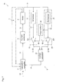
Fig. 1 is a block diagram illustrating a control circuit according to a first embodiment of the present invention; -
Fig. 2 is a graph illustrating a first weight coefficient R1 according to the first embodiment; -
Fig. 3 is a graph illustrating a second weight coefficient R2 according to the first embodiment; -
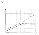
Fig. 4 is a graph illustrating a first detection electric current value I1 and a second detection electric current value I2; -
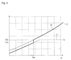
Fig. 5 is a graph illustrating a detection electric current value If when a switch operation is performed; -
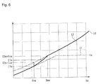
Fig. 6 is a graph illustrating the detection electric current value If when a weight adjustment operation is performed; -
Fig. 7 is a block diagram illustrating a control circuit according to a second embodiment of the present invention; -
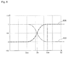
Fig. 8 is a graph illustrating weight coefficients R1 and R2 according to a third embodiment of the present invention; and -
Fig. 9 shows graphs illustrating weight coefficients R1, R2, and R3 according to a fourth embodiment of the present invention. - The particulars shown herein are by way of example and for purposes of illustrative discussion of the embodiments of the present invention only and are presented in the cause of providing what is believed to be the most useful and readily understood description of the principles and conceptual aspects of the present invention. In this regard, no attempt is made to show structural details of the present invention in more detail than is necessary for the fundamental understanding of the present invention, the description taken with the drawings making apparent to those skilled in the art how the forms of the present invention may be embodied in practice.
-
Fig. 1 illustrates a control circuit of amotor control device 1 according to a first embodiment of the present invention. Themotor control device 1 controls amotor 2 installed in displacement mechanisms of each axis of a coordinate measuring device, for example. Themotor control device 1 performs feedback control based on a command signal CS input from an external operation command device. Therefore, themotor control device 1 includes a controller (a calculation controller 3 and an electric current controller 4) controlling themotor 2 and is configured by a triple feedback control system having aspeed loop 6 and aposition loop 7 outside of an electriccurrent loop 5. - The calculation controller 3 outputs an electric current command value Ic based on the command signal CS. The electric
current controller 4 supplies driving electric current Ir to themotor 2 based on the electric current command value Ic. When themotor 2 is driven by the driving electric current Ir, a present electric current Im of themotor 2 is detected through the electriccurrent loop 5 and is fed as a detection electric current value If back to the calculation controller 3. - When one of the displacement mechanisms is operated by the
motor 2, a present speed Vm of the displacement mechanism is detected through thespeed loop 6 and is fed as a detection speed Vf back to the calculation controller 3. In addition, a present position Pm of the displacement mechanism is detected through theposition loop 7 and is fed as a detection position Pf back to the calculation controller 3. - The electric
current loop 5 includes a plurality of detection systems based on the present invention: afirst detection system 10, asecond detection system 20, and also an electriccurrent calculator 30 summing output signals from each of thesystems detection systems sensors weight adjusters sensors motor 2. Theweight adjusters current calculator 30. - In other words, in the
first detection system 10, thefirst sensor 11 detects the electric current Im of themotor 2 and outputs the detection electric current value I1. Then, thefirst weight adjuster 12 multiplies the detection electric current value I1 by the weight coefficient R1 and a resulting signal I1· R1 is output to the electriccurrent calculator 30. Similarly, in thesecond detection system 20, thesecond sensor 21 detects the electric current Im of themotor 2 and outputs the detection electric current value I2. Then, thesecond weight adjuster 22 multiplies the detection electric current value I2 by the weight coefficient R2 and a resulting signal I2· R2 is output to the electriccurrent calculator 30. - The electric
current calculator 30 combines the output signal I1· R1 from thefirst detection system 10 and the signal I2· R2 from thesecond detection system 20 and returns the detection electric current value If=I1·R1+I2·R2 to the calculation controller 3. - In the present embodiment, in the
first sensor 11 of thefirst detection system 10, a high accuracy electric current sensor is used having a narrow electric current detection range but a high degree of detection accuracy. In addition, in thesecond sensor 21 of thesecond detection system 20, a wide range electric current sensor is used having a wide electric current detection range but a low degree of detection accuracy. In order to switch gradually between thefirst detection system 10 and thesecond detection system 20, thefirst weight adjuster 12 and thesecond weight adjuster 22 are provided with the weight coefficients R1 and R2 having the characteristics shown inFigs. 2 and3 . - In this example, in the
first weight adjuster 12 and thesecond weight adjuster 22, the detection electriccurrent value 12 of the second sensor 21 (the electric current sensor having the wide range) is a common reference signal. Further, in order to define an operation range within which switching between thesystems - In
Fig. 2 , when the detection electric current value I2 is less than the lower limit value Ics, the weight coefficient R1 of thefirst weight adjuster 12 is constant at R1 = 1. When the detection electric current value I2 is in a range of equal to or greater than the lower limit value Ics and less than the upper limit value Ice, the weight coefficient R1 is simply decreased and is expressed by the weight coefficient R1 = 1 - (I2 - Ics) / (Ice - Ics). When the detection electric current value I2 is equal to or greater than the upper limit value Ice, the weight coefficient R1 is constant at R1 = 0. - In
Fig. 3 , when the detection electric current value I2 is less than the lower limit value Ics, the weight coefficient R2 of thesecond weight adjuster 22 is constant at R2 = 0. When the detection electric current value I2 is in a range of equal to or greater than the lower limit value Ics and less than the upper limit value Ice, the weight coefficient R2 is simply increased and expressed by R2 = (I2 - Ics) / (Ice - Ics). When the detection electric current value I2 is equal to or greater than the upper limit value Ice, the weight coefficient R2 is constant at R2 = 1. - With these weight coefficients R1 and R2, the sum of the coefficients (R1 + R2) is always 1. In other words, when the detection electric
current value 12 is less than the lower limit value Ics, the sum of the weight coefficients is constant at (R1 + R2) = 1. When the detection electric current value I2 is in a range of equal to or greater than the lower limit value Ics and less than the upper limit value Ice, the weight coefficient R1 is simply increased while the weight coefficient R2 is simply decreased, and the sum of the weight coefficients is constant at (R1 + R2) = 1. When the detection electric current value I2 is equal to or greater than the upper limit value Ice, the sum of the coefficients is constant at (R1 + R2) = 1. - Accordingly, by using the weight coefficients R1 and R2, the output signals from each of the
sensors current calculator 30, when the detection electric current value I2 is less than the lower limit value Ics, because the weight coefficient R1 is at R1 = 1 and the weight coefficient R2 is at R2 = 0, the detection electric current value If is defined at If=I1· R1 + I2· R2 = I1. - In addition, when the detection electric
current value 12 is in a range of equal to or greater than the lower limit value Ics and less than the upper limit value Ice, the weight coefficient R1 is simply increased while the weight coefficient R2 is simply decreased. Therefore, the detection electric current value If has the detection electric current values I1 and I2 mixed at ratios corresponding to the weight coefficients R1 and R2. Moreover, when the detection electric current value I2 is less than the upper limit value Ice, because the weight coefficient R1 is at R1 = 0 and the weight coefficient R2 is at R2 = 1, the detection electric current value If is defined at If = I1· R1 + I2· R2 = I2. - The gradual switch between the
first detection system 10 and thesecond detection system 20 according to the present embodiment, and more specifically the switching between the detection electric current values I1 and 12 of the detection electric current value If, is performed as follows. - As shown in
Fig. 4 , even though the electric current Im of themotor 2 is the same, the detection electric current value I1 of thefirst sensor 11 and the detection electric current value I2 of thesecond sensor 21 are not the same. Thefirst sensor 11, which is the high accuracy electric current sensor with a high degree of electric current detection accuracy but a narrow detection range, is used in a region where the electric current Im of themotor 2 is minute. Therefore, when the electric current Im of themotor 2 becomes large, the electric current Im exceeds the detection range of thefirst sensor 11 and the detection electric current value I1 enters a saturated state at a saturated electric current value Is. - In contrast, the
second sensor 21 is the wide range electric current sensor having low electric current detection accuracy but a wide detection range, and therefore the detection electric current value I2 is not saturated and can be used over an entire variation range of the electric current Im of themotor 2. Further, even though the electric current Im is the same in the effective detection range (non-saturated area) of thefirst sensor 11, there is a deviation in the detection electric current values I1 and I2 from each of thesensors - The
first sensor 11 and thesecond sensor 21 are used by switching between thesensors motor 2. Specifically, the high accuracyfirst sensor 11 is used in a region where the electric current Im of themotor 2 is small while the wide rangesecond sensor 21 is used in a region where the electric current Im of themotor 2 is large. In this way, the present embodiment switches between the detection electric current values I1 and I2 output from each sensor and feeds back to the calculation controller 3 as the detection electric current value If. - As shown in
Fig. 5 , based on the output deviation of thefirst sensor 11 and thesecond sensor 21 mentioned above, at a time when the electric current Im = Imo, the detection electric current value I1 = I1o differs from the detection electriccurrent value 12 = I2o. Therefore, when the detection electric current values I1 and I2 are switched simultaneously at the time when the electric current Im = Imo, variation having a steep step shape is caused in the detection electric current value If. When such a step-shaped variation in the detection electric current value If is fed back to the calculation controller 3, the calculation controller 3 sends the electric current command value Ic corresponding to the step-shaped variation to the electriccurrent controller 4. As a result, concerns may arise such as an abrupt operation of themotor 2, excessive flow of electric current, and the like. - However, in the present embodiment, by performing a gradual switch using the weight coefficients R1 and R2, abrupt variation in the detection electric current value If is prevented. In
Fig. 6 , when the detection electriccurrent value 12 which is the reference signal is the lower limit value Ics, the detection electric current value I2 is defined at I2 = I2s (= Ics) and the detection electric current value I1 is at I1 = I1s (I1s < I2s), and the electric current Im of themotor 2 is Im = Ims. In addition, when the detection electriccurrent value 12 which is the reference signal is the upper limit value Ice, the detection electric current value I2 is defined at I2 = I2e (=Ice), the detection electric current value I1 is at I1 = I1e (I1e < I2e), and the electric current Im of themotor 2 is Im = Ime. - In the region where the detection electric current value I2 which is the reference signal is smaller than the lower limit value Ics (region where the electric current Im < Ims), the weight coefficient R1 is at R1 = 1 and the weight coefficient R2 is at R2 = 0. Therefore, the detection electric current value If = I1; that is, only the output signal from the
first sensor 11 is selected. In the region where the detection electric current value I2 is larger than the lower limit value Ics and smaller than the upper limit value (region where the electric current Im is between Ims and Ime), the detection electric current values I1 and I2 are mixed in accordance with the weight coefficients R1 and R2, and the detection electric current If is switched gradually from the detection electric current value I1 of thefirst sensor 11 to the detection electric current value I2 of thesecond sensor 21. In the region where the detection electriccurrent value 12 is larger than the upper limit value Ice (region where electric current Im > Ims), the weight coefficient R1 is at R1 = 0 and the weight coefficient R2 is R2 = 1, so the detection electric current value If = I2; that is, only the output signal from thesecond sensor 21 is selected. - Accordingly, in the present embodiment, switching between the detection electric current value I1 of the
first sensor 11 and the detection electric current value I2 of thesecond sensor 21 is performed at a gentle pace, and therefore the abrupt variation in the detection electric current value If can be prevented. Further, in each of thefirst detection system 10 and thesecond detection system 20, the output signal from thesecond sensor 21 is defined as the common reference signal, and therefore the weight coefficients R1 and R2 can accurately and readily be correlated (for example, defined so that the total equals 1). - Furthermore, the output signal from the second sensor having a wide detection range is used as the reference signal, and therefore an entire range of the operation status of the
motor 2 can be covered and the switching between thefirst detection system 10 and thesecond detection system 20 can be performed accurately. In addition, by defining the lower limit value Ics and the upper limit value Ice of the common reference signal, the switching behavior of thefirst detection system 10 and thesecond detection system 20 can be freely configured. For example, configurations are possible such as performing relatively sudden switching in narrow ranges, extending a state where the plurality of systems operate in parallel in wide ranges, or the like. -
Fig. 7 illustrates a second embodiment according to the present invention. Amotor control device 1A of the present embodiment has a basic configuration similar to that of themotor control device 1 of the first embodiment, described above. Accordingly, duplicative descriptions of shared configurations are omitted and only those configurations that are differentiated are described below. - In the first embodiment above, the
first weight adjuster 12 and thesecond weight adjuster 22 are provided to thefirst detection system 10 andsecond detection system 20 as shown inFig. 1 . By referring to the detection electriccurrent value 12 which is the reference signal for both, and by adjusting the weight coefficients R1 and R2, the detection electric current value If=I1· R1 + I2· R2 is returned to the calculation controller 3. - In contrast, in the present embodiment, as shown in
Fig. 7 , afirst weight adjuster 12A and asecond weight adjuster 22A are provided to thefirst detection system 10 andsecond detection system 20. However, each adjuster is simply an amplifier. Aweight definer 40 is connected to thefirst weight adjuster 12A and thesecond weight adjuster 22A. - The
weight definer 40 adjusts, in reference to the detection electriccurrent value 12 which is the reference signal, the weight coefficients R1 and R2 based on the lower limit value Ics and the upper limit value Ice, which are similar to the first embodiment, and outputs the weight coefficients R1 and R2 to thefirst weight adjuster 12A and thesecond weight adjuster 22A. Based on these weight coefficients R1 and R2, thefirst weight adjuster 12A and thesecond weight adjuster 22A adjust a balance between the detection electric current value I1 of thefirst sensor 11 and the detection electriccurrent value 12 of thesecond sensor 21. - As a result, in the electric
current calculator 30, similar to the first embodiment, the detection electric current value If=I1· R1 + I2· R2 is calculated and can be returned to the calculation controller 3. Accordingly, in the second embodiment, effects similar to that of the first embodiment above can be achieved. -
Fig. 8 illustrates a third embodiment according to the present invention. In the present embodiment, a basic configuration is the same as themotor control device 1 according to the first embodiment above, however the setting of the weight coefficients R1 and R2 is different. Accordingly, weight coefficients R1 and R2 having a different configuration are described below. - In the first embodiment above, the weight coefficients R1 and R2 are shown in a broken line changing direction at the lower limit value Ics and the upper limit value Ice. In contrast, in the present embodiment, a weight coefficient R2B is defined by a hyperbolic tangent function. Specifically, R2B is defined as R2B = tanh (I2 - Ih) + 0.5, where Ih = (Ics + Ice) / 2. Meanwhile, a weight coefficient R1B is defined as R1B = 1 - R2b (locus where R2B is vertically inverted).
- In this embodiment, the weight coefficients R1B and R2B are schematically similar to the broken line of the weight coefficients R1 and R2 of the first embodiment, and the bends of the line are rendered in a smooth curve. Accordingly, the variation in the detection electric current value If= I1· R1 + I2· R2 returning to the calculation controller 3 can be further smoothly curved. In addition, with the hyperbolic function, setting of the
first weight adjuster 12 and thesecond weight adjuster 22 can be simplified. -
Fig. 9 illustrates a fourth embodiment according to the present invention. The present embodiment has the same basic configuration as themotor control device 1 of the first embodiment above. However, whereas two systems (thefirst detection system 10 and the second detection system 20) are arranged in the first embodiment, three systems (the first, the second and a third detection system) are used in the present embodiment. Further, an example of the detection system having the three systems is to merely add one more system similar to the configuration of thedetection systems motor control device 1 ofFig. 1 , and therefore this is omitted from the drawings. The detection electric current value If returned to the calculation controller 3 is If = I1· R1 + I2· R2 + I3· R3. -
Fig. 9 illustrates the weight coefficients R1, R2, and R3 enabling gradual switching between the three systems. The weight coefficient R1 is constant at R1 = 1 in the region where the detection electriccurrent value 12 which is the reference signal is smaller than a first lower limit value Ics1. The weight coefficient R1 gradually decreases when the detection electriccurrent value 12 is equal to or greater than the first lower limit value Ics1 and is constant at R1 = 0 when the detection electric current value I2 is equal to or greater than a first upper limit value Ice1. - The weight coefficient R2 is constant at R2 = 0 in the region where the detection electric
current value 12 which is the reference signal is smaller than the first lower limit value Ics1. The weight coefficient R2 gradually increases when the detection electric current value I2 is equal to or greater than the first lower limit value Ics1 and is constant at R2 = 1 when the detection electric current value I2 is equal to or greater than the first upper limit value Ice1. Further, the weight coefficient R2 gradually decreases when the detection electric current value I2 is equal to or greater than a second lower limit value Ics2 and is constant at R2 = 0 when the detection electric current value I2 is equal to or greater than a second upper limit value Ice2. - The weight coefficient R3 is constant at R3 = 0 in the region where the detection electric current value I2 which is the reference signal is smaller than the second lower limit value Ics2. The weight coefficient R3 gradually increases when the detection electric
current value 12 is equal to or greater than the second lower limit value Ics2 and is constant at R3 = 1 when the detection electric current value I2 is equal to or greater than the second upper limit value Ice2. - In this embodiment, the weight coefficients R1, R2, and R3 enable sequentially switching between the three systems of the detection system. In each switching region, a switching signal from each switched system also can be gradually increased or decreased, and the variation in the detection electric current value If returned to the calculation controller 3 can be more gentle.
- The present invention is not limited to the above-described configurations of the embodiments, and includes modifications within a scope capable of achieving the advantages of the present invention. For example, in each of the embodiments above, a sensor of each system has a different detection range and detection accuracy. However, a plurality of detection systems using other differing detected characteristics, differing detection principles, or the like can be configured and the present invention may be applied to switch between these detection systems.
- In addition, in each of the embodiments above, the present invention is applied to the electric
current loop 5. However, the present invention may be applied to thespeed loop 6 or theposition loop 7. Furthermore, the present invention is not limited to a measuring apparatus such as a coordinate measuring apparatus, and may be applied to a machine tool and the like. - The present invention relates to a feedback control device and can be used in a control device performing feedback control of a motor of various mechanical devices.
- It is noted that the foregoing examples have been provided merely for the purpose of explanation and are in no way to be construed as limiting of the present invention. While the present invention has been described with reference to exemplary embodiments, it is understood that the words which have been used herein are words of description and illustration, rather than words of limitation. Changes may be made, within the purview of the appended claims, as presently stated and as amended, without departing from the scope and spirit of the present invention in its aspects. Although the present invention has been described herein with reference to particular structures, materials and embodiments, the present invention is not intended to be limited to the particulars disclosed herein; rather, the present invention extends to all functionally equivalent structures, methods and uses, such as are within the scope of the appended claims.
- The present invention is not limited to the above described embodiments, and various variations and modifications may be possible without departing from the scope of the present invention.
Claims (4)
- A feedback control device comprising:a controller configured to control a motor; anda detector configured to detect an operation status of the motor and returning the status to the controller, the detector comprising a plurality of detection systems and a calculator summing output signals from the detection systems,wherein each detection system of the plurality of detection systems comprises:a sensor configured to detect the operation status of the motor; andan adjuster configured to output to the calculator, the output signal from the sensor multiplied by a weight coefficient.
- The feedback control device according to claim 1, wherein:each adjuster is configured to use the output signal from any of the sensors as a common reference signal, andwhen the reference signal changes from a lower limit value to an upper limit value defined in advance, the weight coefficient is defined so as to gradually increase or decrease.
- The feedback control device according to claim 2, wherein:the plurality of detection systems include a first detection system and a second detection system,the first detection system includes a first sensor, the first sensor having a higher detection accuracy than that of the sensor of the second detection system,the second detection system includes a second sensor, the second sensor having a wider detection range than that of the sensor of the first detection system, andthe adjuster of the first detection system and the adjuster of the second detection system each use the output signal from the second sensor as the reference signal and define the weight coefficient.
- The feedback control device according to claim 3, wherein:the detector is an electric current detector;the first sensor is an electric current sensor having a detection accuracy higher than that of the second sensor; andthe second sensor is an electric current sensor having a detection range wider than that of the first sensor.
Applications Claiming Priority (1)
| Application Number | Priority Date | Filing Date | Title |
|---|---|---|---|
| JP2015140635A JP2017022933A (en) | 2015-07-14 | 2015-07-14 | Feedback control device |
Publications (2)
| Publication Number | Publication Date |
|---|---|
| EP3118582A1 true EP3118582A1 (en) | 2017-01-18 |
| EP3118582B1 EP3118582B1 (en) | 2018-05-23 |
Family
ID=56615825
Family Applications (1)
| Application Number | Title | Priority Date | Filing Date |
|---|---|---|---|
| EP16179197.5A Not-in-force EP3118582B1 (en) | 2015-07-14 | 2016-07-13 | Feedback control device |
Country Status (4)
| Country | Link |
|---|---|
| US (1) | US9859838B2 (en) |
| EP (1) | EP3118582B1 (en) |
| JP (1) | JP2017022933A (en) |
| CN (1) | CN106357197B (en) |
Families Citing this family (1)
| Publication number | Priority date | Publication date | Assignee | Title |
|---|---|---|---|---|
| JP7047794B2 (en) * | 2019-02-08 | 2022-04-05 | オムロン株式会社 | Controllers and control programs |
Citations (10)
| Publication number | Priority date | Publication date | Assignee | Title |
|---|---|---|---|---|
| EP0658755A1 (en) * | 1993-12-15 | 1995-06-21 | Balzers Aktiengesellschaft | Procedure for evaluating the output signals of two pressure sensors, corresponding device with two sensors and pressure sensor head |
| WO1999030215A1 (en) * | 1997-12-05 | 1999-06-17 | Rosemount Inc. | Multiple range transition method and apparatus for process control sensors |
| JP2003021566A (en) * | 2001-07-10 | 2003-01-24 | Teijin Seiki Co Ltd | Silicon diaphragm type vacuum pressure sensor device and pressure measuring method using the device |
| JP2006266738A (en) * | 2005-03-22 | 2006-10-05 | Denso Corp | Sensitivity switching sensor circuit and electronic circuit device using sensitivity switching sensor circuit |
| US20080270046A1 (en) * | 2007-04-25 | 2008-10-30 | Brooks Automation, Inc. | Pressure measurement instrument and method |
| JP2008309752A (en) * | 2007-06-18 | 2008-12-25 | Dia Shinku Kk | Pressure sensor output correction method and pressure sensor output correction apparatus |
| JP2009053164A (en) * | 2007-08-29 | 2009-03-12 | Denso Corp | Physical quantity sensor |
| JP2013021804A (en) | 2011-07-11 | 2013-01-31 | Mitsutoyo Corp | Positioning control device |
| US20130085724A1 (en) * | 2011-09-30 | 2013-04-04 | Freescale Semiconductor, Inc | Method and apparatus for calculating sensor modelling coefficients |
| JP2014183609A (en) | 2013-03-18 | 2014-09-29 | Mitsutoyo Corp | Control apparatus, control method, and control program |
Family Cites Families (9)
| Publication number | Priority date | Publication date | Assignee | Title |
|---|---|---|---|---|
| JP2003032801A (en) * | 2001-07-17 | 2003-01-31 | Fuji Heavy Ind Ltd | Electric vehicle current measurement device |
| JP2007208613A (en) * | 2006-02-01 | 2007-08-16 | Sanyo Electric Co Ltd | Automatic gain control circuit and receiver employing the same |
| DE102009054924A1 (en) * | 2009-12-18 | 2011-06-22 | SB LiMotive Company Ltd., Kyonggi | Method for determining the state of charge of a battery pack |
| JP5549636B2 (en) * | 2011-04-13 | 2014-07-16 | トヨタ自動車株式会社 | Electric power steering device |
| EP2544364B1 (en) * | 2011-07-08 | 2014-08-27 | Siemens Aktiengesellschaft | Torque observer on the basis of the measurement of output current and output voltages |
| JP5397785B2 (en) * | 2011-08-01 | 2014-01-22 | 株式会社デンソー | Control device for three-phase rotating machine |
| JP5939228B2 (en) * | 2012-12-28 | 2016-06-22 | 株式会社デンソー | AC motor control device |
| JP5984743B2 (en) * | 2013-05-30 | 2016-09-06 | 三菱電機株式会社 | Vehicle state detection device |
| IL235022A0 (en) * | 2014-10-06 | 2015-02-01 | Vladimir Kogan | Motor servo-drive for high performance motion control |
-
2015
- 2015-07-14 JP JP2015140635A patent/JP2017022933A/en active Pending
-
2016
- 2016-06-23 US US15/190,775 patent/US9859838B2/en not_active Expired - Fee Related
- 2016-07-13 EP EP16179197.5A patent/EP3118582B1/en not_active Not-in-force
- 2016-07-14 CN CN201610554873.6A patent/CN106357197B/en not_active Expired - Fee Related
Patent Citations (10)
| Publication number | Priority date | Publication date | Assignee | Title |
|---|---|---|---|---|
| EP0658755A1 (en) * | 1993-12-15 | 1995-06-21 | Balzers Aktiengesellschaft | Procedure for evaluating the output signals of two pressure sensors, corresponding device with two sensors and pressure sensor head |
| WO1999030215A1 (en) * | 1997-12-05 | 1999-06-17 | Rosemount Inc. | Multiple range transition method and apparatus for process control sensors |
| JP2003021566A (en) * | 2001-07-10 | 2003-01-24 | Teijin Seiki Co Ltd | Silicon diaphragm type vacuum pressure sensor device and pressure measuring method using the device |
| JP2006266738A (en) * | 2005-03-22 | 2006-10-05 | Denso Corp | Sensitivity switching sensor circuit and electronic circuit device using sensitivity switching sensor circuit |
| US20080270046A1 (en) * | 2007-04-25 | 2008-10-30 | Brooks Automation, Inc. | Pressure measurement instrument and method |
| JP2008309752A (en) * | 2007-06-18 | 2008-12-25 | Dia Shinku Kk | Pressure sensor output correction method and pressure sensor output correction apparatus |
| JP2009053164A (en) * | 2007-08-29 | 2009-03-12 | Denso Corp | Physical quantity sensor |
| JP2013021804A (en) | 2011-07-11 | 2013-01-31 | Mitsutoyo Corp | Positioning control device |
| US20130085724A1 (en) * | 2011-09-30 | 2013-04-04 | Freescale Semiconductor, Inc | Method and apparatus for calculating sensor modelling coefficients |
| JP2014183609A (en) | 2013-03-18 | 2014-09-29 | Mitsutoyo Corp | Control apparatus, control method, and control program |
Also Published As
| Publication number | Publication date |
|---|---|
| EP3118582B1 (en) | 2018-05-23 |
| US9859838B2 (en) | 2018-01-02 |
| CN106357197B (en) | 2020-06-26 |
| CN106357197A (en) | 2017-01-25 |
| JP2017022933A (en) | 2017-01-26 |
| US20170019053A1 (en) | 2017-01-19 |
Similar Documents
| Publication | Publication Date | Title |
|---|---|---|
| US12037991B2 (en) | Method and apparatus for controlling power delivered to an SMA actuator | |
| TWI430062B (en) | Device for controlling a motor | |
| EP1922806B1 (en) | System and method for parallel control of variable frequency drives | |
| EP2479107B1 (en) | Aircraft flight control system | |
| CN114096456B (en) | Lane guidance driver assistance device and method for supporting or automating vehicle lateral control | |
| CN108238096A (en) | Torque control unit | |
| US10992241B2 (en) | Control device of motor and storage medium | |
| US10998722B2 (en) | Load-sharing power system | |
| EP3118582B1 (en) | Feedback control device | |
| KR20140049726A (en) | Apparatus and method for controlling motor | |
| KR102075590B1 (en) | Master-slave robot device and guide method for the position of the master of controlling master-slave robot device | |
| EP2808992B1 (en) | Motor control device | |
| KR101388854B1 (en) | Motor driving device, and method for cotrolling motor | |
| US10216173B2 (en) | Motor control device | |
| JPWO2008093486A1 (en) | Moment of inertia identification device, identification method thereof, and motor control device including the identification device | |
| US9821821B2 (en) | Measuring device | |
| CN109716070B (en) | Physical Quantity Measuring Device | |
| US20130197672A1 (en) | Pass-Through Controller for Cascaded Proportional-Integral-Derivative Control Loops | |
| JP2007304850A (en) | Voltage generation circuit and electric appliance provided with the same | |
| CN106980338B (en) | Voltage stabilizer | |
| JP6731141B2 (en) | Skew steady rest control device for suspended loads | |
| JP6554848B2 (en) | Solenoid valve control device | |
| US20130314018A1 (en) | Apparatus and method for controlling motor speed | |
| KR101363318B1 (en) | A method and an apparatus to control pointing of touch-pad | |
| JP2009237821A (en) | Position controller |
Legal Events
| Date | Code | Title | Description |
|---|---|---|---|
| PUAI | Public reference made under article 153(3) epc to a published international application that has entered the european phase |
Free format text: ORIGINAL CODE: 0009012 |
|
| STAA | Information on the status of an ep patent application or granted ep patent |
Free format text: STATUS: THE APPLICATION HAS BEEN PUBLISHED |
|
| AK | Designated contracting states |
Kind code of ref document: A1 Designated state(s): AL AT BE BG CH CY CZ DE DK EE ES FI FR GB GR HR HU IE IS IT LI LT LU LV MC MK MT NL NO PL PT RO RS SE SI SK SM TR |
|
| AX | Request for extension of the european patent |
Extension state: BA ME |
|
| STAA | Information on the status of an ep patent application or granted ep patent |
Free format text: STATUS: REQUEST FOR EXAMINATION WAS MADE |
|
| 17P | Request for examination filed |
Effective date: 20170718 |
|
| RBV | Designated contracting states (corrected) |
Designated state(s): AL AT BE BG CH CY CZ DE DK EE ES FI FR GB GR HR HU IE IS IT LI LT LU LV MC MK MT NL NO PL PT RO RS SE SI SK SM TR |
|
| GRAP | Despatch of communication of intention to grant a patent |
Free format text: ORIGINAL CODE: EPIDOSNIGR1 |
|
| STAA | Information on the status of an ep patent application or granted ep patent |
Free format text: STATUS: GRANT OF PATENT IS INTENDED |
|
| INTG | Intention to grant announced |
Effective date: 20180222 |
|
| GRAS | Grant fee paid |
Free format text: ORIGINAL CODE: EPIDOSNIGR3 |
|
| GRAA | (expected) grant |
Free format text: ORIGINAL CODE: 0009210 |
|
| STAA | Information on the status of an ep patent application or granted ep patent |
Free format text: STATUS: THE PATENT HAS BEEN GRANTED |
|
| AK | Designated contracting states |
Kind code of ref document: B1 Designated state(s): AL AT BE BG CH CY CZ DE DK EE ES FI FR GB GR HR HU IE IS IT LI LT LU LV MC MK MT NL NO PL PT RO RS SE SI SK SM TR |
|
| REG | Reference to a national code |
Ref country code: GB Ref legal event code: FG4D |
|
| REG | Reference to a national code |
Ref country code: CH Ref legal event code: EP |
|
| REG | Reference to a national code |
Ref country code: IE Ref legal event code: FG4D |
|
| REG | Reference to a national code |
Ref country code: AT Ref legal event code: REF Ref document number: 1001877 Country of ref document: AT Kind code of ref document: T Effective date: 20180615 |
|
| REG | Reference to a national code |
Ref country code: DE Ref legal event code: R096 Ref document number: 602016003173 Country of ref document: DE |
|
| REG | Reference to a national code |
Ref country code: NL Ref legal event code: MP Effective date: 20180523 |
|
| REG | Reference to a national code |
Ref country code: LT Ref legal event code: MG4D |
|
| PG25 | Lapsed in a contracting state [announced via postgrant information from national office to epo] |
Ref country code: ES Free format text: LAPSE BECAUSE OF FAILURE TO SUBMIT A TRANSLATION OF THE DESCRIPTION OR TO PAY THE FEE WITHIN THE PRESCRIBED TIME-LIMIT Effective date: 20180523 Ref country code: LT Free format text: LAPSE BECAUSE OF FAILURE TO SUBMIT A TRANSLATION OF THE DESCRIPTION OR TO PAY THE FEE WITHIN THE PRESCRIBED TIME-LIMIT Effective date: 20180523 Ref country code: NO Free format text: LAPSE BECAUSE OF FAILURE TO SUBMIT A TRANSLATION OF THE DESCRIPTION OR TO PAY THE FEE WITHIN THE PRESCRIBED TIME-LIMIT Effective date: 20180823 Ref country code: BG Free format text: LAPSE BECAUSE OF FAILURE TO SUBMIT A TRANSLATION OF THE DESCRIPTION OR TO PAY THE FEE WITHIN THE PRESCRIBED TIME-LIMIT Effective date: 20180823 Ref country code: SE Free format text: LAPSE BECAUSE OF FAILURE TO SUBMIT A TRANSLATION OF THE DESCRIPTION OR TO PAY THE FEE WITHIN THE PRESCRIBED TIME-LIMIT Effective date: 20180523 Ref country code: FI Free format text: LAPSE BECAUSE OF FAILURE TO SUBMIT A TRANSLATION OF THE DESCRIPTION OR TO PAY THE FEE WITHIN THE PRESCRIBED TIME-LIMIT Effective date: 20180523 |
|
| PG25 | Lapsed in a contracting state [announced via postgrant information from national office to epo] |
Ref country code: HR Free format text: LAPSE BECAUSE OF FAILURE TO SUBMIT A TRANSLATION OF THE DESCRIPTION OR TO PAY THE FEE WITHIN THE PRESCRIBED TIME-LIMIT Effective date: 20180523 Ref country code: GR Free format text: LAPSE BECAUSE OF FAILURE TO SUBMIT A TRANSLATION OF THE DESCRIPTION OR TO PAY THE FEE WITHIN THE PRESCRIBED TIME-LIMIT Effective date: 20180824 Ref country code: LV Free format text: LAPSE BECAUSE OF FAILURE TO SUBMIT A TRANSLATION OF THE DESCRIPTION OR TO PAY THE FEE WITHIN THE PRESCRIBED TIME-LIMIT Effective date: 20180523 Ref country code: RS Free format text: LAPSE BECAUSE OF FAILURE TO SUBMIT A TRANSLATION OF THE DESCRIPTION OR TO PAY THE FEE WITHIN THE PRESCRIBED TIME-LIMIT Effective date: 20180523 Ref country code: NL Free format text: LAPSE BECAUSE OF FAILURE TO SUBMIT A TRANSLATION OF THE DESCRIPTION OR TO PAY THE FEE WITHIN THE PRESCRIBED TIME-LIMIT Effective date: 20180523 |
|
| REG | Reference to a national code |
Ref country code: AT Ref legal event code: MK05 Ref document number: 1001877 Country of ref document: AT Kind code of ref document: T Effective date: 20180523 |
|
| PG25 | Lapsed in a contracting state [announced via postgrant information from national office to epo] |
Ref country code: RO Free format text: LAPSE BECAUSE OF FAILURE TO SUBMIT A TRANSLATION OF THE DESCRIPTION OR TO PAY THE FEE WITHIN THE PRESCRIBED TIME-LIMIT Effective date: 20180523 Ref country code: PL Free format text: LAPSE BECAUSE OF FAILURE TO SUBMIT A TRANSLATION OF THE DESCRIPTION OR TO PAY THE FEE WITHIN THE PRESCRIBED TIME-LIMIT Effective date: 20180523 Ref country code: SK Free format text: LAPSE BECAUSE OF FAILURE TO SUBMIT A TRANSLATION OF THE DESCRIPTION OR TO PAY THE FEE WITHIN THE PRESCRIBED TIME-LIMIT Effective date: 20180523 Ref country code: AT Free format text: LAPSE BECAUSE OF FAILURE TO SUBMIT A TRANSLATION OF THE DESCRIPTION OR TO PAY THE FEE WITHIN THE PRESCRIBED TIME-LIMIT Effective date: 20180523 Ref country code: DK Free format text: LAPSE BECAUSE OF FAILURE TO SUBMIT A TRANSLATION OF THE DESCRIPTION OR TO PAY THE FEE WITHIN THE PRESCRIBED TIME-LIMIT Effective date: 20180523 Ref country code: EE Free format text: LAPSE BECAUSE OF FAILURE TO SUBMIT A TRANSLATION OF THE DESCRIPTION OR TO PAY THE FEE WITHIN THE PRESCRIBED TIME-LIMIT Effective date: 20180523 Ref country code: CZ Free format text: LAPSE BECAUSE OF FAILURE TO SUBMIT A TRANSLATION OF THE DESCRIPTION OR TO PAY THE FEE WITHIN THE PRESCRIBED TIME-LIMIT Effective date: 20180523 |
|
| REG | Reference to a national code |
Ref country code: DE Ref legal event code: R097 Ref document number: 602016003173 Country of ref document: DE |
|
| PG25 | Lapsed in a contracting state [announced via postgrant information from national office to epo] |
Ref country code: SM Free format text: LAPSE BECAUSE OF FAILURE TO SUBMIT A TRANSLATION OF THE DESCRIPTION OR TO PAY THE FEE WITHIN THE PRESCRIBED TIME-LIMIT Effective date: 20180523 Ref country code: IT Free format text: LAPSE BECAUSE OF FAILURE TO SUBMIT A TRANSLATION OF THE DESCRIPTION OR TO PAY THE FEE WITHIN THE PRESCRIBED TIME-LIMIT Effective date: 20180523 |
|
| PG25 | Lapsed in a contracting state [announced via postgrant information from national office to epo] |
Ref country code: MC Free format text: LAPSE BECAUSE OF FAILURE TO SUBMIT A TRANSLATION OF THE DESCRIPTION OR TO PAY THE FEE WITHIN THE PRESCRIBED TIME-LIMIT Effective date: 20180523 Ref country code: LU Free format text: LAPSE BECAUSE OF NON-PAYMENT OF DUE FEES Effective date: 20180713 |
|
| PLBE | No opposition filed within time limit |
Free format text: ORIGINAL CODE: 0009261 |
|
| STAA | Information on the status of an ep patent application or granted ep patent |
Free format text: STATUS: NO OPPOSITION FILED WITHIN TIME LIMIT |
|
| REG | Reference to a national code |
Ref country code: BE Ref legal event code: MM Effective date: 20180731 |
|
| REG | Reference to a national code |
Ref country code: IE Ref legal event code: MM4A |
|
| PG25 | Lapsed in a contracting state [announced via postgrant information from national office to epo] |
Ref country code: FR Free format text: LAPSE BECAUSE OF NON-PAYMENT OF DUE FEES Effective date: 20180723 Ref country code: IE Free format text: LAPSE BECAUSE OF NON-PAYMENT OF DUE FEES Effective date: 20180713 |
|
| 26N | No opposition filed |
Effective date: 20190226 |
|
| PG25 | Lapsed in a contracting state [announced via postgrant information from national office to epo] |
Ref country code: BE Free format text: LAPSE BECAUSE OF NON-PAYMENT OF DUE FEES Effective date: 20180731 Ref country code: SI Free format text: LAPSE BECAUSE OF FAILURE TO SUBMIT A TRANSLATION OF THE DESCRIPTION OR TO PAY THE FEE WITHIN THE PRESCRIBED TIME-LIMIT Effective date: 20180523 |
|
| PG25 | Lapsed in a contracting state [announced via postgrant information from national office to epo] |
Ref country code: AL Free format text: LAPSE BECAUSE OF FAILURE TO SUBMIT A TRANSLATION OF THE DESCRIPTION OR TO PAY THE FEE WITHIN THE PRESCRIBED TIME-LIMIT Effective date: 20180523 |
|
| PG25 | Lapsed in a contracting state [announced via postgrant information from national office to epo] |
Ref country code: MT Free format text: LAPSE BECAUSE OF NON-PAYMENT OF DUE FEES Effective date: 20180713 |
|
| REG | Reference to a national code |
Ref country code: CH Ref legal event code: PL |
|
| PG25 | Lapsed in a contracting state [announced via postgrant information from national office to epo] |
Ref country code: TR Free format text: LAPSE BECAUSE OF FAILURE TO SUBMIT A TRANSLATION OF THE DESCRIPTION OR TO PAY THE FEE WITHIN THE PRESCRIBED TIME-LIMIT Effective date: 20180523 |
|
| PG25 | Lapsed in a contracting state [announced via postgrant information from national office to epo] |
Ref country code: CH Free format text: LAPSE BECAUSE OF NON-PAYMENT OF DUE FEES Effective date: 20190731 Ref country code: LI Free format text: LAPSE BECAUSE OF NON-PAYMENT OF DUE FEES Effective date: 20190731 Ref country code: PT Free format text: LAPSE BECAUSE OF FAILURE TO SUBMIT A TRANSLATION OF THE DESCRIPTION OR TO PAY THE FEE WITHIN THE PRESCRIBED TIME-LIMIT Effective date: 20180523 |
|
| PG25 | Lapsed in a contracting state [announced via postgrant information from national office to epo] |
Ref country code: MK Free format text: LAPSE BECAUSE OF NON-PAYMENT OF DUE FEES Effective date: 20180523 Ref country code: CY Free format text: LAPSE BECAUSE OF FAILURE TO SUBMIT A TRANSLATION OF THE DESCRIPTION OR TO PAY THE FEE WITHIN THE PRESCRIBED TIME-LIMIT Effective date: 20180523 Ref country code: HU Free format text: LAPSE BECAUSE OF FAILURE TO SUBMIT A TRANSLATION OF THE DESCRIPTION OR TO PAY THE FEE WITHIN THE PRESCRIBED TIME-LIMIT; INVALID AB INITIO Effective date: 20160713 |
|
| PG25 | Lapsed in a contracting state [announced via postgrant information from national office to epo] |
Ref country code: IS Free format text: LAPSE BECAUSE OF FAILURE TO SUBMIT A TRANSLATION OF THE DESCRIPTION OR TO PAY THE FEE WITHIN THE PRESCRIBED TIME-LIMIT Effective date: 20180923 |
|
| PGFP | Annual fee paid to national office [announced via postgrant information from national office to epo] |
Ref country code: DE Payment date: 20230719 Year of fee payment: 8 |
|
| PGFP | Annual fee paid to national office [announced via postgrant information from national office to epo] |
Ref country code: GB Payment date: 20240723 Year of fee payment: 9 |
|
| REG | Reference to a national code |
Ref country code: DE Ref legal event code: R119 Ref document number: 602016003173 Country of ref document: DE |
|
| PG25 | Lapsed in a contracting state [announced via postgrant information from national office to epo] |
Ref country code: DE Free format text: LAPSE BECAUSE OF NON-PAYMENT OF DUE FEES Effective date: 20250201 |
|
| GBPC | Gb: european patent ceased through non-payment of renewal fee |
Effective date: 20250713 |
|
| PG25 | Lapsed in a contracting state [announced via postgrant information from national office to epo] |
Ref country code: GB Free format text: LAPSE BECAUSE OF NON-PAYMENT OF DUE FEES Effective date: 20250713 |