EP3118574A1 - Verfahren zur herstellung eines formbauteils sowie vorrichtung zur durchführung des verfahrens - Google Patents
Verfahren zur herstellung eines formbauteils sowie vorrichtung zur durchführung des verfahrens Download PDFInfo
- Publication number
- EP3118574A1 EP3118574A1 EP16179181.9A EP16179181A EP3118574A1 EP 3118574 A1 EP3118574 A1 EP 3118574A1 EP 16179181 A EP16179181 A EP 16179181A EP 3118574 A1 EP3118574 A1 EP 3118574A1
- Authority
- EP
- European Patent Office
- Prior art keywords
- projection
- projection device
- component
- projections
- molded component
- Prior art date
- Legal status (The legal status is an assumption and is not a legal conclusion. Google has not performed a legal analysis and makes no representation as to the accuracy of the status listed.)
- Granted
Links
Images

Classifications
-
- G—PHYSICS
- G01—MEASURING; TESTING
- G01B—MEASURING LENGTH, THICKNESS OR SIMILAR LINEAR DIMENSIONS; MEASURING ANGLES; MEASURING AREAS; MEASURING IRREGULARITIES OF SURFACES OR CONTOURS
- G01B11/00—Measuring arrangements characterised by the use of optical techniques
- G01B11/02—Measuring arrangements characterised by the use of optical techniques for measuring length, width or thickness
- G01B11/06—Measuring arrangements characterised by the use of optical techniques for measuring length, width or thickness for measuring thickness ; e.g. of sheet material
-
- G—PHYSICS
- G01—MEASURING; TESTING
- G01B—MEASURING LENGTH, THICKNESS OR SIMILAR LINEAR DIMENSIONS; MEASURING ANGLES; MEASURING AREAS; MEASURING IRREGULARITIES OF SURFACES OR CONTOURS
- G01B11/00—Measuring arrangements characterised by the use of optical techniques
- G01B11/02—Measuring arrangements characterised by the use of optical techniques for measuring length, width or thickness
Definitions
- the invention relates to a method for producing a molded component and to an apparatus for carrying out the method.
- the manufacturing process of molded parts is characterized by an interactive approach.
- a target geometry is created by applying or ablating.
- the actual state must be compared with the target geometry.
- the work of loading or removal must be interrupted and the mold component may be moved.
- a comparison between the desired geometry and the actual geometry can be performed by detecting the surface. These interruptions slow down the process.
- From the DE 10 2013 114 707 A1 is a method for performing and controlling a processing step on a workpiece, using a device with a single projector, a Fotogrammetrie Skimmer, and a control unit, the relative position of the projector and Fotogrammetrie observed known.
- From the DE 10 2011 015 987 A1 is a system for the visual presentation of information on real objects with a single projection unit for the graphic or visual transmission of information on an object known.
- the object of the invention is to provide a method in which the comparison of the actual state with the desired geometry can be carried out continuously and without interrupting the production process.
- the method according to the invention for producing a molded component with a desired geometry serves to produce a molded component, wherein the molded component is produced by application and / or removal. From a first projection device from a first direction, at least one first first projection is projected onto the shaped component and from a second projection device from a second direction at least one first second projection is projected onto the shaped component.
- the first direction is different from the second direction.
- the first first projection and the first second projection coincide, provided that the shaped components has reached the target geometry at the location of the projection.
- the first first projection and the first second projection fall apart unless the desired geometry for the molded component has been reached. If the shaped component is too high, then the first first projection in the direction of the first projection device, thus in the first direction, is displaced from the first second projection. This allows an operator to identify during processing whether further material must be removed. Thus, no interruption of the processing for comparing the actual shape with the desired geometry is necessary. If the shaped component is too low, then the first first projection is shifted in the direction of the second projection device, thus in the second direction, from the first second projection. This allows an operator to identify during processing whether additional material needs to be applied. Thus, no interruption of the processing for comparing the actual shape with the desired geometry is necessary.
- the first projection device projects n first projections and the second projection device projects n second projections.
- n projections in each case, an arbitrary three-dimensional surface of the desired geometry can be projected to a first approximation.
- the n projections can each have an identical appearance, have n different appearances or be formed in each case from groups of projections with identical appearances.
- material is removed from the molded component, provided that the first first projection is displaced in the first direction from the first second projection.
- the removal can, for example, by grinding, cutting, for example, planing, sanding, ablation, such as laser ablation done.
- material is applied to the molding component, provided that the first first projection is displaced in the direction opposite to the first direction from the first second projection.
- the application can be done for example by lamination.
- the speed of the application or removal of material of the molded component is selected as a function of the distance of the first first projection from the first second projection. The larger the distance, the greater the deviation from the target geometry. It therefore makes sense to choose a higher speed of application or removal. Therefore, a higher speed with a greater distance is particularly preferred only.
- the velocity is preferably determined spatially resolved.
- the molded component consists of plastic layers, in particular glass fiber reinforced plastic.
- the first projection device projects a first color and the second projection device projects a second color.
- the different colors allow easy detection of deviation by the operator. In this way it is particularly easy to see whether the actual shape is above or below the desired geometry.
- the first projection device projects a first shape and the second projection device projects a second shape.
- the first shape is a cross and the second shape is an X. This also makes it possible to distinguish well and thus to easily detect the deviation of the actual shape from the desired geometry.
- the first projection device projects a first shape and the second projection device projects a second shape that is different from the first shape.
- the first shape and the second shape are chosen such that the size of the deviation of the actual geometry from the target geometry can be read or at least estimated based on the overlap.
- the first shape is an X or cross and the second shape is concentric circles.
- the concentric circles are divided into a second and a third color, so that the direction of the deviation can be read off.
- first of all the mold component is detected, in particular the position of reference points of the mold component is detected. From the detected position of the reference points, the exact position of the desired geometry between the reference points is calculated and the at least one first first projection and the at least one first second projection are projected.
- the invention relates to a device for carrying out the method according to the invention.
- the device has a first projection device and a second projection device.
- the distance of the first projection device from the second projection device, the distance of the first projection device from the molding component and the distance of the second projection device from the molding component resulting from the required manufacturing tolerance.
- the angle at which the projection impinges must be adapted to the resolvable distance between two projections. If two projections can be distinguished which have at least one distance a (optical resolution) and if the manufacturing tolerance in height is not to exceed the value b, then the angle ⁇ must fulfill the following condition: tan ⁇ ⁇ a / b
- An angle of 2 ⁇ thus results between a beam of the first projection device and a second beam of the projection device.
- the ratio of the distance between the first projection device and the second projection device to the distance between the two projection devices to the mold component results from this.
- the method according to the invention is shown schematically on the basis of the device.
- the figures are greatly simplified, and in particular, for the sake of simplicity and illustration of the type, the distance between the projection devices and the surface is much greater than the distance of the projections. For this reason, the beam path is shown only schematically for each projection.
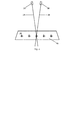
- Fig. 1 is the surface of the mold member 40 above the target geometry 10.
- first projection device 20 a group of five first projections 22 are projected onto the surface of the mold member, which are circular.
- second projection device 30 a group of five second projections 32 are projected on the surface of the molding member, which are cross-shaped.
- the first beam 24 outlines the path between the first projection device 20 and the first projection 22.
- the second beam 34 outlines the path between the second projection device 30 and the second projection 32. Based on the distance between the first projection 23 and the second projection 32 recognizable that the surface of the mold member 40 does not correspond to the desired geometry 10, but that the surface of the mold member 40 is disposed above the target geometry 10.
- Fig. 2 the case is shown that the surface of the mold member 40 is disposed below the target geometry 10.
- Fig. 1 There is an offset between the first projections 22 and the second projections 32, the order now appears reversed. As a result, an operator can easily recognize that the surface of the molded component 40 is arranged below the desired geometry 10.
- Fig. 3 the case is shown that the surface of the mold component 40 corresponds exactly to the desired geometry 10. As a result, the first projections 22 and the second projections 32 coincide. The engineer immediately recognizes that further processing is not necessary.
Landscapes
- Physics & Mathematics (AREA)
- General Physics & Mathematics (AREA)
- Injection Moulding Of Plastics Or The Like (AREA)
- Moulds For Moulding Plastics Or The Like (AREA)
Abstract
Description
- Die Erfindung betrifft ein Verfahren zur Herstellung eines Formbauteils sowie eine Vorrichtung zur Durchführung des Verfahrens.
- Der Herstellungsprozess von Formbauteilen ist durch ein interaktives Vorgehen geprägt. In mehreren Schritten wird eine Soll-Geometrie durch Auftragen oder Abtragen hergestellt. Am Ende eines Iterationsschritts ist der Ist-Stand mit der Soll-Geometrie abzugleichen. Hierzu muss die Arbeit des Auf- oder Abtragens unterbrochen und das Formbauteil gegebenenfalls bewegt werden. Gegebenenfalls kann ein Vergleich zwischen der Soll-Geometrie und der Ist-Geometrie durch Erfassen der Oberfläche durchgeführt werden. Diese Unterbrechungen führen zu einer Verlangsamung des Prozesses.
- Aus der
DE 10 2013 114 707 A1 ist Verfahren zur Durchführung und Kontrolle eines Bearbeitungsschritts an einem Werkstück, unter Verwendung einer Vorrichtung mit einem einzigen Projektor, einer Fotogrammetrieeinrichtung sowie einer Steuereinheit, der die relative Position von Projektor und Fotogrammetrieeinrichtung bekannt. - Aus der
DE 10 2011 015 987 A1 ist ein System zur visuellen Darstellung von Informationen auf realen Objekten mit einer einzigen Projektionseinheit zur grafischen oder bildlichen Übertragung einer Information auf ein Objekt bekannt. - Aufgabe der Erfindung ist es, ein Verfahren bereitzustellen, bei welchem der Vergleich des Ist-Standes mit der Soll-Geometrie kontinuierlich und ohne Unterbrechung des Herstellungsprozesses durchgeführt werden kann.
- Gelöst wird diese Aufgabe durch das Verfahren mit den in Anspruch 1 angegebenen Merkmalen, sowie durch die Vorrichtung mit den in Anspruch 10 angegebenen Merkmalen. Vorteilhafte Weiterbildungen ergeben sich aus den Unteransprüchen, der nachfolgenden Beschreibung sowie den Zeichnungen.
- Das erfindungsgemäße Verfahren zur Herstellung eines Formbauteils mit einer Soll-Geometrie dient zur Herstellung eines Formbauteils, wobei das Formbauteil durch Auftragen und/oder Abtragen hergestellt wird. Aus einer ersten Projektionsvorrichtung aus einer ersten Richtung wird wenigstens eine erste erste Projektion auf das Formbauteil projiziert und aus einer zweiten Projektionsvorrichtung aus einer zweiten Richtung wenigstens eine erste zweite Projektion auf das Formbauteil projiziert. Hierbei ist die erste Richtung von der zweiten Richtung verschieden. Die erste erste Projektion und die erste zweite Projektion fallen aufeinander, sofern das Formbauteile am Ort der Projektion die Soll-Geometrie erreicht hat.
- Durch die Projektion aus zwei unterschiedlichen Richtungen fallen die erste erste Projektion und die erste zweite Projektion auseinander, sofern die Soll-Geometrie für das Formbauteil noch nicht erreicht ist. Ist das Formbauteil zu hoch, so ist die erste erste Projektion in Richtung auf die erste Projektionsvorrichtung, somit in die erste Richtung, von der ersten zweiten Projektion verschoben. Hierdurch kann ein Bearbeiter während der Bearbeitung erkennen, ob weiteres Material abgetragen werden muss. Somit ist keine Unterbrechung der Bearbeitung zum Vergleich der Ist-Form mit der Soll-Geometrie notwendig. Ist das Formbauteil zu niedrig, so ist die erste erste Projektion in Richtung auf die zweite Projektionsvorrichtung, somit in die zweite Richtung, von der ersten zweiten Projektion verschoben. Hierdurch kann ein Bearbeiter während der Bearbeitung erkennen, ob weiteres Material aufgetragen werden muss. Somit ist keine Unterbrechung der Bearbeitung zum Vergleich der Ist-Form mit der Soll-Geometrie notwendig.
- In einer weiteren Ausführungsform der Erfindung projizieren die erste Projektionsvorrichtung n erste Projektionen und die zweite Projektionsvorrichtung n zweite Projektionen. Durch die Verwendung von jeweils n Projektionen kann eine beliebige dreidimensionale Oberfläche der Soll-Geometrie in erster Näherung projiziert werden. Hierbei können die n Projektionen jeweils ein identisches Aussehen haben, n verschiedene Aussehen haben oder jeweils aus Gruppen von Projektionen mit jeweils identischem Aussehen gebildet sein.
- In einer weiteren Ausführungsform der Erfindung wird von dem Formbauteil Material abgetragen, sofern die erste erste Projektion in der ersten Richtung von der ersten zweiten Projektion verschoben ist. Das Abtragen kann beispielsweise durch Schleifen, Spanen, beispielsweise Hobeln, Schmirgeln, Ablatieren, beispielsweise Laser-Ablatieren, erfolgen.
- In einer weiteren Ausführungsform der Erfindung wird zu dem Formbauteil Material aufgetragen, sofern die erste erste Projektion in die der ersten Richtung entgegengesetzte Richtung von der ersten zweiten Projektion verschoben ist. Das Auftragen kann beispielsweise durch Lamination erfolgen.
- In einer weiteren Ausführungsform der Erfindung wird die Geschwindigkeit des Auftragens bzw. Abtragens von Material des Formbauteils in Abhängigkeit des Abstandes der ersten ersten Projektion von der ersten zweiten Projektion gewählt. Je größer der Abstand ist, desto größer ist die Abweichung von der Soll-Geometrie. Es ist daher sinnvoll eine höhere Geschwindigkeit des Auftragens bzw. Abtragen zu wählen. Daher wird besonders bevorzugt eine höhere Geschwindigkeit bei größerem Abstand nur gewählt. Bei der Verwendung von n Projektionen wird die Geschwindigkeit vorzugsweise ortsaufgelöst ermittelt.
- In einer weiteren Ausführungsform der Erfindung besteht das Formbauteil aus Kunststoffschichten, insbesondere glasfaserverstärktem Kunststoff.
- In einer weiteren Ausführungsform der Erfindung projiziert die erste Projektionsvorrichtung eine erste Farbe und die zweite Projektionsvorrichtung eine zweite Farbe. Die unterschiedlichen Farben ermöglichen eine leichte Erkennung der Abweichung durch den Bearbeiter. Hierdurch ist insbesondere leicht zu erkennen ob die Ist-Form oberhalb oder unterhalb der Soll-Geometrie liegt.
- In einer weiteren Ausführungsform der Erfindung projiziert die erste Projektionsvorrichtung eine erste Form und die zweite Projektionsvorrichtung eine zweite Form. Beispielsweise handelt es sich bei der ersten Form um ein Kreuz und bei der zweiten Form um ein X. Auch hierdurch ist eine gute Unterscheidbarkeit und somit eine leichte Erkennung der Abweichung der Ist- Form von der Soll-Geometrie möglich.
- In einer alternativen Ausführungsform projizieren die erste Projektionsvorrichtung eine erste Form und die zweite Projektionsvorrichtung eine zweite Form, die von der ersten Form unterschiedlich ist. Die erste Form und die zweite Form sind dabei derart gewählt, dass anhand der Überschneidung die beiden Formen die Größe der Abweichung der Ist- von der Soll-Geometrie abgelesen oder zumindest abgeschätzt werden kann. Beispielsweise handelt es sich bei der ersten Form um ein X oder Kreuz und bei der zweiten Form um konzentrische Kreise.
- Besonders bevorzugt sind die konzentrischen Kreise in eine zweite und eine dritte Farbe unterteilt, so dass die Richtung der Abweichung abgelesen werden kann.
- In einer weiteren Ausführungsform der Erfindung wird zunächst das Formbauteil erfasst, insbesondere wird die Position von Referenzpunkten des Formbauteils erfasst. Aus der erfassten Position der Referenzpunkte wird die exakte Lage der Soll-Geometrie zwischen den Referenzpunkten errechnet und die wenigstens eine erste erste Projektion und die wenigstens eine erste zweite Projektion projiziert.
- In einem weiteren Aspekt betrifft die Erfindung eine Vorrichtung zur Durchführung des erfindungsgemäßen Verfahrens. Die Vorrichtung weist hierzu eine erste Projektionsvorrichtung und eine zweite Projektionsvorrichtung auf.
- Der Abstand der ersten Projektionsvorrichtung von der zweiten Projektionsvorrichtung, der Abstand der ersten Projektionsvorrichtung von dem Formbauteil und der Abstand der zweiten Projektionsvorrichtung von dem Formbauteil ergeben sich aus der geforderten Fertigungstoleranz. Um eine geforderte Fertigungstoleranz in der Höhe zu erreichen, muss der Winkel, unter welchem die Projektion auftrifft, an den auflösbaren Abstand zwischen zwei Projektionen angepasst werden. Können zwei Projektionen unterschieden werden, welche mindestens einen Abstand a aufwiesen (optische Auflösung) und soll die Fertigungstoleranz in der Höhe den Wert b nicht übersteigen, so muss der Winkel α folgende Bedingung erfüllen:

- Zwischen einem Strahl der ersten Projektionsvorrichtung und einem zweiten Strahl der Projektionsvorrichtung ergibt sich somit ein Winkel von 2α. Das Verhältnis vom Abstand zwischen der ersten Projektionsvorrichtung und der zweiten Projektionsvorrichtung zum Abstand der beiden Projektionsvorrichtungen zum Formbauteil ergibt sich hieraus.
- Nachfolgend ist die erfindungsgemäße Vorrichtung anhand eines in den Zeichnungen dargestellten Ausführungsbeispiels näher erläutert.
- Fig. 1
- schematische Darstellung, Oberfläche oberhalb der Soll-Geometrie
- Fig. 1
- schematische Darstellung, Oberfläche unterhalb der Soll-Geometrie
- Fig. 3
- schematische Darstellung, Oberfläche auf der Soll-Geometrie
- In den
Fig. 1 bis Fig. 3 ist das erfindungsgemäße Verfahren anhand der Vorrichtung schematisch dargestellt. Hierbei sind die Figuren stark vereinfacht, insbesondere ist zur Vereinfachung wie Darstellung der Art, dass die Entfernung zwischen den Projektionsvorrichtungen und der Oberfläche sehr viel größer als der Abstand der Projektionen ist. Aus diesem Grund ist der Strahlengang lediglich schematisch für jeweils eine Projektion dargestellt. - In
Fig. 1 ist die Oberfläche des Formbauteils 40 oberhalb der Soll-Geometrie 10. Aus der ersten Projektionsvorrichtung 20 wird eine Gruppe von fünf ersten Projektionen 22 auf die Oberfläche des Formbauteils projiziert, welche kreisförmig sind. Aus der zweiten Projektionsvorrichtung 30 wird eine Gruppe von fünf zweiten Projektionen 32 auf die Oberfläche des Formbauteils projiziert, welche kreuzförmige sind. Der erste Strahl 24 skizziert den Verlauf zwischen der ersten Projektionsvorrichtung 20 und der ersten Projektion 22. Der zweite Strahl 34 skizziert den Verlauf zwischen der zweiten Projektionsvorrichtung 30 und der zweiten Projektion 32. Anhand des Abstandes zwischen der ersten Projektion 23 und der zweiten Projektion 32 ist erkennbar, dass die Oberfläche des Formbauteils 40 nicht der Soll-Geometrie 10 entspricht, sondern dass die Oberfläche des Formbauteils 40 oberhalb der Soll-Geometrie 10 angeordnet ist. - In
Fig. 2 ist der Fall dargestellt, dass die Oberfläche des Formbauteils 40 unterhalb der Soll-Geometrie 10 angeordnet ist. Wie inFig. 1 kommt es zu einem Versatz zwischen den ersten Projektionen 22 und den zweiten Projektionen 32, wobei die Reihenfolge jetzt umgekehrt erscheint. Hierdurch kann ein Bearbeiter leicht erkennen, dass die Oberfläche des Formbauteils 40 unterhalb der Soll-Geometrie 10 angeordnet ist. - In
Fig. 3 ist der Fall dargestellt, dass die Oberfläche des Formbauteils 40 exakt der Soll-Geometrie 10 entspricht. Hierdurch fallen die ersten Projektionen 22 und die zweiten Projektionen 32 übereinander. Der Bearbeiter erkennt unmittelbar, dass eine weitere Bearbeitung nicht notwendig ist. - Bezugszeichen:
- 10
- Soll-Geometrie
- 20
- erste Projektionsvorrichtung
- 22
- erste Projektion
- 24
- erster Strahl
- 30
- zweite Projektionsvorrichtung
- 32
- zweite Projektion
- 34
- zweiter Strahl
- 40
- Oberfläche des Formbauteils
Claims (10)
- Verfahren zur Herstellung eines Formbauteils mit einer Soll-Geometrie (10), wobei das Formbauteil durch Auftragen und/oder Abtragen hergestellt wird, dadurch gekennzeichnet, dass aus einer ersten Projektionsvorrichtung (20) aus einer ersten Richtung wenigstens eine erste erste Projektion (22) auf das Formbauteil projiziert wird, wobei aus einer zweiten Projektionsvorrichtung (30) aus einer zweiten Richtung wenigstens eine erste zweite Projektion (32) auf das Formbauteil projiziert wird, wobei die erste erste Projektion (22) und die erste zweite Projektion (32) aufeinander fallen, sofern das Formbauteile am Ort der Projektion die Soll-Geometrie (10) erreicht hat.
- Verfahren nach Anspruch 1, dadurch gekennzeichnet, dass die erste Projektionsvorrichtung (20) n erste Projektionen (22) und die zweite Projektionsvorrichtung (30) n zweite Projektionen (32) projizieren.
- Verfahren nach einem der vorstehenden Ansprüche, dadurch gekennzeichnet, dass von dem Formbauteil Material abgetragen wird, sofern die erste erste Projektion (22) in der ersten Richtung von der ersten zweiten Projektion (32) verschoben ist.
- Verfahren nach einem der vorstehenden Ansprüche, dadurch gekennzeichnet, dass zu dem Formbauteil Material aufgetragen wird, sofern die erste erste Projektion (22) in die der ersten Richtung entgegengesetzte Richtung von der ersten zweiten Projektion (32) verschoben ist.
- Verfahren nach einem der vorstehenden Ansprüche, dadurch gekennzeichnet, dass die Geschwindigkeit des Auftragens bzw. Abtragens von Material des Formbauteils in Abhängigkeit des Abstandes der ersten ersten Projektion (22) von der ersten zweiten Projektion (32) gewählt wird.
- Verfahren nach Anspruch 5, dadurch gekennzeichnet, dass eine höhere Geschwindigkeit bei größerem Abstand gewählt wird.
- Verfahren nach einem der vorstehenden Ansprüche, dadurch gekennzeichnet, dass das Formbauteil aus Kunststoffschichten, insbesondere glasfaserverstärktem Kunststoff, besteht.
- Verfahren nach einem der vorstehenden Ansprüche, dadurch gekennzeichnet, dass das Auftragen durch Laminieren erfolgt.
- Verfahren nach einem der vorstehenden Ansprüche, dadurch gekennzeichnet, dass die erste Projektionsvorrichtung (20) eine erste Farbe projiziert und die zweite Projektionsvorrichtung (30) eine zweite Farbe projiziert.
- Vorrichtung zur Durchführung eines Verfahrens gemäß einem der vorstehenden Ansprüche, wobei die Vorrichtung eine erste Projektionsvorrichtung (20) und eine zweite Projektionsvorrichtung (30) aufweist.
Applications Claiming Priority (1)
| Application Number | Priority Date | Filing Date | Title |
|---|---|---|---|
| DE102015213124.6A DE102015213124A1 (de) | 2015-07-14 | 2015-07-14 | Verfahren zur Herstellung eines Formbauteils sowie Vorrichtung zur Durchführung des Verfahrens |
Publications (2)
| Publication Number | Publication Date |
|---|---|
| EP3118574A1 true EP3118574A1 (de) | 2017-01-18 |
| EP3118574B1 EP3118574B1 (de) | 2018-09-19 |
Family
ID=56800122
Family Applications (1)
| Application Number | Title | Priority Date | Filing Date |
|---|---|---|---|
| EP16179181.9A Active EP3118574B1 (de) | 2015-07-14 | 2016-07-13 | Verfahren zur herstellung eines formbauteils |
Country Status (3)
| Country | Link |
|---|---|
| EP (1) | EP3118574B1 (de) |
| DE (1) | DE102015213124A1 (de) |
| ES (1) | ES2699349T3 (de) |
Citations (4)
| Publication number | Priority date | Publication date | Assignee | Title |
|---|---|---|---|---|
| US5056922A (en) * | 1988-02-26 | 1991-10-15 | Canadian Patents And Development Limited/Societe Canadienne Des Brevets Et D'exploitation Limitee | Method and apparatus for monitoring the surface profile of a moving workpiece |
| US5442573A (en) * | 1992-04-28 | 1995-08-15 | Taymer Industries Inc. | Laser thickness gauge |
| DE102011015987A1 (de) | 2011-04-04 | 2012-10-04 | EXTEND3D GmbH | System und Verfahren zur visuellen Darstellung von Informationen auf realen Objekten |
| DE102013114707A1 (de) | 2013-12-20 | 2015-06-25 | EXTEND3D GmbH | Verfahren zur Durchführung und Kontrolle eines Bearbeitungsschritts an einem Werkstück |
Family Cites Families (2)
| Publication number | Priority date | Publication date | Assignee | Title |
|---|---|---|---|---|
| WO1990009560A1 (en) * | 1989-02-17 | 1990-08-23 | John Lysaght (Australia) Limited | Distance gauge |
| FR2746705B1 (fr) * | 1996-03-27 | 1998-06-19 | Heidelberg Harris Sa | Dispositif de mesure sans contact de modifications de position d'une nappe continue de matiere |
-
2015
- 2015-07-14 DE DE102015213124.6A patent/DE102015213124A1/de not_active Ceased
-
2016
- 2016-07-13 ES ES16179181T patent/ES2699349T3/es active Active
- 2016-07-13 EP EP16179181.9A patent/EP3118574B1/de active Active
Patent Citations (4)
| Publication number | Priority date | Publication date | Assignee | Title |
|---|---|---|---|---|
| US5056922A (en) * | 1988-02-26 | 1991-10-15 | Canadian Patents And Development Limited/Societe Canadienne Des Brevets Et D'exploitation Limitee | Method and apparatus for monitoring the surface profile of a moving workpiece |
| US5442573A (en) * | 1992-04-28 | 1995-08-15 | Taymer Industries Inc. | Laser thickness gauge |
| DE102011015987A1 (de) | 2011-04-04 | 2012-10-04 | EXTEND3D GmbH | System und Verfahren zur visuellen Darstellung von Informationen auf realen Objekten |
| DE102013114707A1 (de) | 2013-12-20 | 2015-06-25 | EXTEND3D GmbH | Verfahren zur Durchführung und Kontrolle eines Bearbeitungsschritts an einem Werkstück |
Also Published As
| Publication number | Publication date |
|---|---|
| EP3118574B1 (de) | 2018-09-19 |
| DE102015213124A1 (de) | 2017-01-19 |
| ES2699349T3 (es) | 2019-02-08 |
Similar Documents
| Publication | Publication Date | Title |
|---|---|---|
| EP2670557B1 (de) | Verfahren zum abtrennen eines randabschnitts eines werkstücks mittels eines lasertrennschnitts sowie zugehörige laserschneidvorrichtung | |
| DE102006051556A1 (de) | Verfahren zum Strukturieren von Solarmodulen und Strukturierungsvorrichtung | |
| DE102015205631B4 (de) | Verfahren zum automatisierten Bedrucken einer gekrümmten Oberfläche eines dreidimensionalen Objekts | |
| DE102018125620A1 (de) | Verfahren und Vorrichtung zum Schneiden einer Blechplatine aus einem kontinuierlich geförderten Blechband | |
| DE102017116174A1 (de) | Vorrichtung und Verfahren zum Reinigen eines Fahrzeugs mit mindestens einer Außenfläche, die um einen Neigungswinkel zur Vertikalen geneigt ist | |
| EP2956267A1 (de) | Verfahren zur steuerung eines gerätesystems beim trennen eines werkstückes entlang einer trennlinie | |
| EP3359913A1 (de) | Überwachung eines sicherheitsrelevanten parameters eines koordinatenmessgeräts | |
| DE102018124208A1 (de) | Verfahren und Vorrichtung zur Überwachung eines Bearbeitungsprozesses eines Werkstücks mittels eines Laserstrahls | |
| DE102019007972A1 (de) | Vorrichtung und Verfahren zum Herstellen eines dreidimensionalen Formgegenstandes | |
| DE102004062163A1 (de) | Verfahren zur Ermittlung einer möglichen Kollision mindestens zweier zueinander beweglicher Objekte | |
| DE102013203383A1 (de) | Verfahren zum Schneiden einer Blechplatine | |
| DE102015121437A1 (de) | Vorrichtung und Verfahren zur Herstellung eines dreidimensionalen metallischen Formkörpers | |
| EP3118574B1 (de) | Verfahren zur herstellung eines formbauteils | |
| DE102019123654B3 (de) | Verfahren zum Herstellen von mindestens einer mehrere Musterelemente umfassenden Musterfigur mittels eines Lasers | |
| DE102016224456A1 (de) | Verfahren zum Ausrichten von Bauteilen | |
| DE102016003640A1 (de) | Laserbearbeitungsvorrichtung mit Abstandssteuerfunktion und Steuerung hierfür | |
| EP3245567B1 (de) | Verfahren zum aktualisieren von daten einer materialbearbeitungsmaschine sowie zugehörige materialbearbeitungsmaschine und austauschbare maschinenkomponente | |
| DE102014220519B4 (de) | Verfahren zur Positionierung eines bildaufnehmenden Elements zu einer optischen Einrichtung und Verwendung des Verfahrens | |
| DE102018114156B3 (de) | Verfahren zur Steuerung eines Roboters, insbesondere eines Industrieroboters, sowie Vorrichtung zur Steuerung des Roboters | |
| DE102019216571A1 (de) | Codierung von Bauteilen während der Herstellung im 3D-Druckverfahren | |
| EP3030191B1 (de) | Verfahren für eine kalibrierung einer sensorvorrichtung für die regelung der ausrichtung einer ausleuchtvorrichtung und ausleuchtsystem | |
| DE102013221852A1 (de) | Vorrichtung zur Laserbeschriftung eines Bauteils | |
| DE102019123045A1 (de) | Dummy-Vorrichtung und deren Verwendungen sowie Automatisierungssystem | |
| DE102016112271A1 (de) | Einrichtung und Verfahren zur Positionierung einer Flachglaseinheit | |
| DE102018126106A1 (de) | Verfahren zur Bestimmung eines Freischnittpunkts beim Trennen eines Werkstückteils von einem Restteil und Programmiereinrichtung hierfür |
Legal Events
| Date | Code | Title | Description |
|---|---|---|---|
| PUAI | Public reference made under article 153(3) epc to a published international application that has entered the european phase |
Free format text: ORIGINAL CODE: 0009012 |
|
| STAA | Information on the status of an ep patent application or granted ep patent |
Free format text: STATUS: THE APPLICATION HAS BEEN PUBLISHED |
|
| AK | Designated contracting states |
Kind code of ref document: A1 Designated state(s): AL AT BE BG CH CY CZ DE DK EE ES FI FR GB GR HR HU IE IS IT LI LT LU LV MC MK MT NL NO PL PT RO RS SE SI SK SM TR |
|
| AX | Request for extension of the european patent |
Extension state: BA ME |
|
| STAA | Information on the status of an ep patent application or granted ep patent |
Free format text: STATUS: REQUEST FOR EXAMINATION WAS MADE |
|
| 17P | Request for examination filed |
Effective date: 20170201 |
|
| RBV | Designated contracting states (corrected) |
Designated state(s): AL AT BE BG CH CY CZ DE DK EE ES FI FR GB GR HR HU IE IS IT LI LT LU LV MC MK MT NL NO PL PT RO RS SE SI SK SM TR |
|
| RAP1 | Party data changed (applicant data changed or rights of an application transferred) |
Owner name: THYSSENKRUPP MARINE SYSTEMS GMBH Owner name: THYSSENKRUPP AG |
|
| STAA | Information on the status of an ep patent application or granted ep patent |
Free format text: STATUS: EXAMINATION IS IN PROGRESS |
|
| 17Q | First examination report despatched |
Effective date: 20180122 |
|
| GRAP | Despatch of communication of intention to grant a patent |
Free format text: ORIGINAL CODE: EPIDOSNIGR1 |
|
| STAA | Information on the status of an ep patent application or granted ep patent |
Free format text: STATUS: GRANT OF PATENT IS INTENDED |
|
| INTG | Intention to grant announced |
Effective date: 20180403 |
|
| GRAS | Grant fee paid |
Free format text: ORIGINAL CODE: EPIDOSNIGR3 |
|
| GRAA | (expected) grant |
Free format text: ORIGINAL CODE: 0009210 |
|
| STAA | Information on the status of an ep patent application or granted ep patent |
Free format text: STATUS: THE PATENT HAS BEEN GRANTED |
|
| AK | Designated contracting states |
Kind code of ref document: B1 Designated state(s): AL AT BE BG CH CY CZ DE DK EE ES FI FR GB GR HR HU IE IS IT LI LT LU LV MC MK MT NL NO PL PT RO RS SE SI SK SM TR |
|
| REG | Reference to a national code |
Ref country code: GB Ref legal event code: FG4D Free format text: NOT ENGLISH |
|
| REG | Reference to a national code |
Ref country code: CH Ref legal event code: EP |
|
| REG | Reference to a national code |
Ref country code: DE Ref legal event code: R084 Ref document number: 502016002004 Country of ref document: DE |
|
| REG | Reference to a national code |
Ref country code: AT Ref legal event code: REF Ref document number: 1043760 Country of ref document: AT Kind code of ref document: T Effective date: 20181015 |
|
| REG | Reference to a national code |
Ref country code: IE Ref legal event code: FG4D Free format text: LANGUAGE OF EP DOCUMENT: GERMAN |
|
| REG | Reference to a national code |
Ref country code: DE Ref legal event code: R096 Ref document number: 502016002004 Country of ref document: DE |
|
| REG | Reference to a national code |
Ref country code: NL Ref legal event code: MP Effective date: 20180919 |
|
| PG25 | Lapsed in a contracting state [announced via postgrant information from national office to epo] |
Ref country code: BG Free format text: LAPSE BECAUSE OF FAILURE TO SUBMIT A TRANSLATION OF THE DESCRIPTION OR TO PAY THE FEE WITHIN THE PRESCRIBED TIME-LIMIT Effective date: 20181219 Ref country code: GR Free format text: LAPSE BECAUSE OF FAILURE TO SUBMIT A TRANSLATION OF THE DESCRIPTION OR TO PAY THE FEE WITHIN THE PRESCRIBED TIME-LIMIT Effective date: 20181220 Ref country code: LT Free format text: LAPSE BECAUSE OF FAILURE TO SUBMIT A TRANSLATION OF THE DESCRIPTION OR TO PAY THE FEE WITHIN THE PRESCRIBED TIME-LIMIT Effective date: 20180919 Ref country code: SE Free format text: LAPSE BECAUSE OF FAILURE TO SUBMIT A TRANSLATION OF THE DESCRIPTION OR TO PAY THE FEE WITHIN THE PRESCRIBED TIME-LIMIT Effective date: 20180919 Ref country code: NO Free format text: LAPSE BECAUSE OF FAILURE TO SUBMIT A TRANSLATION OF THE DESCRIPTION OR TO PAY THE FEE WITHIN THE PRESCRIBED TIME-LIMIT Effective date: 20181219 Ref country code: FI Free format text: LAPSE BECAUSE OF FAILURE TO SUBMIT A TRANSLATION OF THE DESCRIPTION OR TO PAY THE FEE WITHIN THE PRESCRIBED TIME-LIMIT Effective date: 20180919 Ref country code: RS Free format text: LAPSE BECAUSE OF FAILURE TO SUBMIT A TRANSLATION OF THE DESCRIPTION OR TO PAY THE FEE WITHIN THE PRESCRIBED TIME-LIMIT Effective date: 20180919 |
|
| REG | Reference to a national code |
Ref country code: ES Ref legal event code: FG2A Ref document number: 2699349 Country of ref document: ES Kind code of ref document: T3 Effective date: 20190208 |
|
| REG | Reference to a national code |
Ref country code: LT Ref legal event code: MG4D |
|
| PG25 | Lapsed in a contracting state [announced via postgrant information from national office to epo] |
Ref country code: HR Free format text: LAPSE BECAUSE OF FAILURE TO SUBMIT A TRANSLATION OF THE DESCRIPTION OR TO PAY THE FEE WITHIN THE PRESCRIBED TIME-LIMIT Effective date: 20180919 Ref country code: LV Free format text: LAPSE BECAUSE OF FAILURE TO SUBMIT A TRANSLATION OF THE DESCRIPTION OR TO PAY THE FEE WITHIN THE PRESCRIBED TIME-LIMIT Effective date: 20180919 Ref country code: AL Free format text: LAPSE BECAUSE OF FAILURE TO SUBMIT A TRANSLATION OF THE DESCRIPTION OR TO PAY THE FEE WITHIN THE PRESCRIBED TIME-LIMIT Effective date: 20180919 |
|
| PG25 | Lapsed in a contracting state [announced via postgrant information from national office to epo] |
Ref country code: NL Free format text: LAPSE BECAUSE OF FAILURE TO SUBMIT A TRANSLATION OF THE DESCRIPTION OR TO PAY THE FEE WITHIN THE PRESCRIBED TIME-LIMIT Effective date: 20180919 Ref country code: EE Free format text: LAPSE BECAUSE OF FAILURE TO SUBMIT A TRANSLATION OF THE DESCRIPTION OR TO PAY THE FEE WITHIN THE PRESCRIBED TIME-LIMIT Effective date: 20180919 Ref country code: CZ Free format text: LAPSE BECAUSE OF FAILURE TO SUBMIT A TRANSLATION OF THE DESCRIPTION OR TO PAY THE FEE WITHIN THE PRESCRIBED TIME-LIMIT Effective date: 20180919 Ref country code: RO Free format text: LAPSE BECAUSE OF FAILURE TO SUBMIT A TRANSLATION OF THE DESCRIPTION OR TO PAY THE FEE WITHIN THE PRESCRIBED TIME-LIMIT Effective date: 20180919 Ref country code: PL Free format text: LAPSE BECAUSE OF FAILURE TO SUBMIT A TRANSLATION OF THE DESCRIPTION OR TO PAY THE FEE WITHIN THE PRESCRIBED TIME-LIMIT Effective date: 20180919 Ref country code: IS Free format text: LAPSE BECAUSE OF FAILURE TO SUBMIT A TRANSLATION OF THE DESCRIPTION OR TO PAY THE FEE WITHIN THE PRESCRIBED TIME-LIMIT Effective date: 20190119 |
|
| PG25 | Lapsed in a contracting state [announced via postgrant information from national office to epo] |
Ref country code: PT Free format text: LAPSE BECAUSE OF FAILURE TO SUBMIT A TRANSLATION OF THE DESCRIPTION OR TO PAY THE FEE WITHIN THE PRESCRIBED TIME-LIMIT Effective date: 20190119 Ref country code: SM Free format text: LAPSE BECAUSE OF FAILURE TO SUBMIT A TRANSLATION OF THE DESCRIPTION OR TO PAY THE FEE WITHIN THE PRESCRIBED TIME-LIMIT Effective date: 20180919 Ref country code: SK Free format text: LAPSE BECAUSE OF FAILURE TO SUBMIT A TRANSLATION OF THE DESCRIPTION OR TO PAY THE FEE WITHIN THE PRESCRIBED TIME-LIMIT Effective date: 20180919 |
|
| REG | Reference to a national code |
Ref country code: DE Ref legal event code: R097 Ref document number: 502016002004 Country of ref document: DE |
|
| PLBE | No opposition filed within time limit |
Free format text: ORIGINAL CODE: 0009261 |
|
| STAA | Information on the status of an ep patent application or granted ep patent |
Free format text: STATUS: NO OPPOSITION FILED WITHIN TIME LIMIT |
|
| PG25 | Lapsed in a contracting state [announced via postgrant information from national office to epo] |
Ref country code: DK Free format text: LAPSE BECAUSE OF FAILURE TO SUBMIT A TRANSLATION OF THE DESCRIPTION OR TO PAY THE FEE WITHIN THE PRESCRIBED TIME-LIMIT Effective date: 20180919 |
|
| 26N | No opposition filed |
Effective date: 20190620 |
|
| REG | Reference to a national code |
Ref country code: DE Ref legal event code: R081 Ref document number: 502016002004 Country of ref document: DE Owner name: THYSSENKRUPP MARINE SYSTEMS GMBH, DE Free format text: FORMER OWNERS: THYSSENKRUPP AG, 45143 ESSEN, DE; THYSSENKRUPP MARINE SYSTEMS GMBH, 24143 KIEL, DE Ref country code: DE Ref legal event code: R081 Ref document number: 502016002004 Country of ref document: DE Owner name: THYSSENKRUPP AG, DE Free format text: FORMER OWNERS: THYSSENKRUPP AG, 45143 ESSEN, DE; THYSSENKRUPP MARINE SYSTEMS GMBH, 24143 KIEL, DE |
|
| PG25 | Lapsed in a contracting state [announced via postgrant information from national office to epo] |
Ref country code: SI Free format text: LAPSE BECAUSE OF FAILURE TO SUBMIT A TRANSLATION OF THE DESCRIPTION OR TO PAY THE FEE WITHIN THE PRESCRIBED TIME-LIMIT Effective date: 20180919 |
|
| PG25 | Lapsed in a contracting state [announced via postgrant information from national office to epo] |
Ref country code: MC Free format text: LAPSE BECAUSE OF FAILURE TO SUBMIT A TRANSLATION OF THE DESCRIPTION OR TO PAY THE FEE WITHIN THE PRESCRIBED TIME-LIMIT Effective date: 20180919 |
|
| REG | Reference to a national code |
Ref country code: CH Ref legal event code: PL |
|
| PG25 | Lapsed in a contracting state [announced via postgrant information from national office to epo] |
Ref country code: TR Free format text: LAPSE BECAUSE OF FAILURE TO SUBMIT A TRANSLATION OF THE DESCRIPTION OR TO PAY THE FEE WITHIN THE PRESCRIBED TIME-LIMIT Effective date: 20180919 |
|
| REG | Reference to a national code |
Ref country code: BE Ref legal event code: MM Effective date: 20190731 |
|
| PG25 | Lapsed in a contracting state [announced via postgrant information from national office to epo] |
Ref country code: LU Free format text: LAPSE BECAUSE OF NON-PAYMENT OF DUE FEES Effective date: 20190713 Ref country code: LI Free format text: LAPSE BECAUSE OF NON-PAYMENT OF DUE FEES Effective date: 20190731 Ref country code: CH Free format text: LAPSE BECAUSE OF NON-PAYMENT OF DUE FEES Effective date: 20190731 Ref country code: BE Free format text: LAPSE BECAUSE OF NON-PAYMENT OF DUE FEES Effective date: 20190731 |
|
| PG25 | Lapsed in a contracting state [announced via postgrant information from national office to epo] |
Ref country code: IE Free format text: LAPSE BECAUSE OF NON-PAYMENT OF DUE FEES Effective date: 20190713 |
|
| PG25 | Lapsed in a contracting state [announced via postgrant information from national office to epo] |
Ref country code: CY Free format text: LAPSE BECAUSE OF FAILURE TO SUBMIT A TRANSLATION OF THE DESCRIPTION OR TO PAY THE FEE WITHIN THE PRESCRIBED TIME-LIMIT Effective date: 20180919 |
|
| PG25 | Lapsed in a contracting state [announced via postgrant information from national office to epo] |
Ref country code: HU Free format text: LAPSE BECAUSE OF FAILURE TO SUBMIT A TRANSLATION OF THE DESCRIPTION OR TO PAY THE FEE WITHIN THE PRESCRIBED TIME-LIMIT; INVALID AB INITIO Effective date: 20160713 Ref country code: MT Free format text: LAPSE BECAUSE OF FAILURE TO SUBMIT A TRANSLATION OF THE DESCRIPTION OR TO PAY THE FEE WITHIN THE PRESCRIBED TIME-LIMIT Effective date: 20180919 |
|
| PG25 | Lapsed in a contracting state [announced via postgrant information from national office to epo] |
Ref country code: MK Free format text: LAPSE BECAUSE OF FAILURE TO SUBMIT A TRANSLATION OF THE DESCRIPTION OR TO PAY THE FEE WITHIN THE PRESCRIBED TIME-LIMIT Effective date: 20180919 |
|
| REG | Reference to a national code |
Ref country code: AT Ref legal event code: MM01 Ref document number: 1043760 Country of ref document: AT Kind code of ref document: T Effective date: 20210713 |
|
| PG25 | Lapsed in a contracting state [announced via postgrant information from national office to epo] |
Ref country code: AT Free format text: LAPSE BECAUSE OF NON-PAYMENT OF DUE FEES Effective date: 20210713 |
|
| REG | Reference to a national code |
Ref country code: DE Ref legal event code: R081 Ref document number: 502016002004 Country of ref document: DE Owner name: THYSSENKRUPP AG, DE Free format text: FORMER OWNERS: THYSSENKRUPP AG, 45143 ESSEN, DE; THYSSENKRUPP MARINE SYSTEMS GMBH, 24143 KIEL, DE Ref country code: DE Ref legal event code: R081 Ref document number: 502016002004 Country of ref document: DE Owner name: TKMS GMBH, DE Free format text: FORMER OWNERS: THYSSENKRUPP AG, 45143 ESSEN, DE; THYSSENKRUPP MARINE SYSTEMS GMBH, 24143 KIEL, DE |
|
| PGFP | Annual fee paid to national office [announced via postgrant information from national office to epo] |
Ref country code: ES Payment date: 20250826 Year of fee payment: 10 |
|
| PGFP | Annual fee paid to national office [announced via postgrant information from national office to epo] |
Ref country code: DE Payment date: 20250722 Year of fee payment: 10 |
|
| PGFP | Annual fee paid to national office [announced via postgrant information from national office to epo] |
Ref country code: IT Payment date: 20250724 Year of fee payment: 10 |
|
| PGFP | Annual fee paid to national office [announced via postgrant information from national office to epo] |
Ref country code: GB Payment date: 20250722 Year of fee payment: 10 |
|
| PGFP | Annual fee paid to national office [announced via postgrant information from national office to epo] |
Ref country code: FR Payment date: 20250725 Year of fee payment: 10 |